1
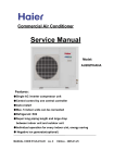
Indoor Unit Operation & Installation Manual
AWSI-CBV009-N11
AWSI-CBV012-N11
AWSI-CBV016-N11
AWSI-CCV018-N11
AWSI-CCV024-N11
AWSI-CCV030-N11
AWSI-CCV048-N11
No.0150510086
Please read this manual carefully before using
Keep this operation manual for future reference
User Manual
Your air conditioner may be subject to any
change owing to the improvement of Airwell
products.
Flow Logic II series multiple air conditioning
systems adopt the consistent running mode,
by which, all indoor units can only be heating
or refrigerating operation at the same time.
Contents
Parts and Functions
1-5
Safety Considerations
6-7
Operation instruction
8-15
To protect the compressor, the air conditioning
unit should be powered on for over 12 hours
before using it.
All indoor units of the same refrigerating
system should use the unified power switch
to ensure that all indoor units are in the state
of being powered on at the same time during
the operation of air conditioner.
Maintenance
Product Features:
1. Hanging-style installation to save space;
2. Automatic display of faults;
3. Function of central control
(optional from our company).
4. The air conditioner is provided with the
function of compensation for power supply.
During operation, when the power supply
fails emergently and resumes again, the air
conditioner returns to the working condition
before power failure, if provided with
compensation function.
5. The operating methods and functions are
same although the shapes of indoor units
are different.
6. Now this indoor unit only has wired
controller function,the indoor unit that has
remote controller function need to set in
factory especially.
16-18
Fault Checkup
19
Installation Procedures
20-26
Electrical Wiring
27-32
Functions of Wired Controller
33
Test Run & Fault Code
34
Disposal
35
whole model
brief model
AWSI-CBV009-N11
CBV009
AWSI-CBV012-N11
CBV012
AWSI-CBV016-N11
CBV016
AWSI-CCV018-N11
CCV018
AWSI-CCV024-N11
CCV024
AWSI-CCV030-N11
CCV030
AWSI-CCV048-N11
CCV048
The brief model is used in this manual for above
models.
Operating Range of Air Conditioner
cooling
dry
indoor
outdoor
indoor
heating
outdoor
max.
DB: 32
WB: 23
min.
DB: 18
WB: 14
max.
DB: 43
DB: -5
WB: 26
min.
max.
DB: 27
min.
DB: 15
max.
min.
DB: 21
DB: -15
WB: 15.5
Parts and Functions
Indoor Units
CBV009-016,CCV018-048
electrical cabinet
wind deflector
(regulate wind direction with
remote controller)
inlet grid
air cleaner (in inlet grid)
1
Parts and Functions
Buttons of the wire controller
Fan speed switch
Change wind speed
Swing switch
Open and close air flap
Mode switch
Choose running mode
TEMP switch
Used for changing
set temperature
Health switch
Used to control oxygen function and
negative ion
MODE
MODE
AUTO
FAN ONLY
COOL
DRY
HEAT
TES
FAN
AUTO
HIGH
MED
LOW
FIX
CENTRAL
OPERATION
STANDBY
PRE-HEAT
DEFROST
FILTER
HEALTH
CHECK
SWING
UNIT NO.
DEMAND
FAN
SWING
HEALTH
TEMP
CLOCK
TIME
Time switch
It is used to
regulate setting
time.
MANUAL
CEN. ADD.
ROOM TEMP.
SYS. ADD.
SET TEMP.
TIMER
SET
CHECK
FILTER
RECOVERY
Clock, timing and
address setting
TIMER CLOCK UP DOWN VENTILATION
ON
AUTO
OFF
DAILY
RECOVERY
NORMAL
RESET
ON/OFF
Timing switch
It is used for choosing timing running
Self-inspection switch
It is used for inspection service
Filter reset
After cleaning air inlet and filter, press this
switch. The unit begins to run
Air change switch
It is used to open
and close air
change function.
The mode is as
follows:
No display-air
change
(automatic)-air
change
(RECOVERY)-air
change (NORMAL)
ON/OFF switch
Do on and off
function. The unit
is on when
pressing it; and is
off when pressing
it again.
Reset key
When in abnormal state, push the reset key
with a spike, which may return the unit to
normal
2
Parts and Functions
Display of the wire controller
Centralized display
When controlled by centralized
controller, and chosen by "centralize or
lock" mode, this information is shown.
Air volume display
Display the setting speed
Running mode display
Show the selected mode
Running display
When the compressor runs, it displays.
Standby display
When the unit is on power and in
"abnormity mode", or outdoor unit
malfunction show alarm , "standby" is
shown to reflect no need to unit.
Health function
display
Unit number
display
Centralized adress
display
System adress
display
Temperature
display
Display the room
temperature, setting
temperature, and
unit number
MODE
MODE
FAN
CENTRAL
AUTO
AUTO
OPERATION
FAN ONLY
COOL
HIGH
MED
STANDBY
PRE-HEAT
DRY
LOW
DEFROST
HEAT
FIX
FILTER
"Defrost" is shown
when defrosting.
TIME
CLOCK
HEALTH
CHECK
UNIT NO.
DEMAND
SWING
TEMP
HEALTH
TES
SWING
MANUAL
CEN. ADD.
ROOM TEMP.
SYS. ADD.
SET TEMP.
TIMER
FAN
When in preheating
status, "preheating"
is shown.
TIMER
SET
RECOVERY
CLOCK UP DOWN VENTILATION
ON
AUTO
OFF
RECOVERY
DAILY
NORMAL
CHECK
FILTER
RESET
Timing operation
display
Show timing operation
content
Filter screen
warning sign
When the sign is
shown, please
clean the filter
screen
ON/OFF
Air change display
Inspection status display
Wind swing display
Demand display
When forced to run,"DEMAND" will be
displayed, or show HH/LL in the
temperature zone.
Remarks
The models in the manual don't have health, filter reset and Air change function.
3
Parts and Functions
5.HEALTH Button
Used to set health operation function.
6.CLOCK Button
Used to set correct time.
Remote controller
28
27
29
26
30
25
31
7.TIMER Button
Used to select TIMER mode:TIMER ON,TIMER
OFF, TIMER ON-OFF.
(Note: if the time of TIMER ON is the same as
TIMER OFF, TIMER ON-OFF cannot be set)
24
32
23
22
33
21
34
8. FILTER Button
Used to set up/down function of filter.
9.CODE Button
Used to select Code A or B, Normally at Code A.
As you cann't controll the indoor unit, please
change the Code to B.
20
35
1
19
TEMP
ON
OFF
2
SWING
18
FAN
3
SLEEP
MODE
4
17
HEALTH
FRESH
10.RESET Button
Press this button by using a sharp article to resume
the correct operation of the remote controller in
case of need, for example, in case of malfunctions
due to electromagnetic disturbance.
11.LIGHT Button
Used to light the control panel
16
5
CLOCK
SET
TIMER
HIGH/SO
FILTER
HEAT
6
15
7
8
RESET
CODE
LIGHT
LOCK
14
13
36
12
9
11
12.LOCK Button
Used to lock operation button and LCD display
contents. If you press this button, the other buttons
come out of function and lock state display appears;
if you press it again, lock state will be no more
active and lock state display will disappear.
10
13.HOUR Adjustment Button
Used to set clock and timer setting
1.TEMP Setting Button
Used to set temperature.
The temperature ranges: 16 C~ 30 C.
In Up/Down function of filter, for controlling up
and down filter.
14.HIGH/SO Button
Used to select HIGH or SOFT operation.
15.SET Button
Used to confirm TIMER and CLOCK settings.
2.SWING Button
If you press this button once, auto swing will be activated.
If you press this button again, the louver will fix in the
present position.
3.Power ON/OFF Button
Used for unit to start or stop.
After power on, the LCD of remote controller will display
the previous operation state (except for TIMER,SLEEP
and SWING state).
4.Operation MODE Button
Used to select operation mode.
Every time you press MODE button, operation mode
changes according to following sequence:
16.FRESH Button
Used to set fresh mode, the unit will draw in fresh
air.
17.SLEEP Button
Used to set sleep mode. (The clock must be
corrected before setting sleep function)
18.FAN Button
Used to select fan speed:LOW,MID,HIGH,AUTO.
19.TIME Display
20.TIMER Display
21.FILTER Display
When the filter need be cleaned, you can press
the FILTER button for 3s, to up/down function.
22.TEMPERATURE Display
Code A:
AUTO
COOL
DRY
HEAT
FAN
23.AUTO SWING Display
4
Parts and Functions
24.HIGN/SO Run Display
25.Code A of controller's state
Code A is used for the units in this manual.
26.SIGNAL SENDING Display
27.Code B of controller's state
28.Fresh Display
29.Auxiliary ELECTRICAL HEATING Display
30.HEALTH Display
Displays when healthy run function is set.
31.Operation MODE Display
AUTO RUN COOL RUN DRY RUN HEAT RUN FAN RUN
32.SLEEP State Display
33.LOCK State Display
34.FAN SPEED Display
Code A
A
U
T
O
LOW
MID
HIGH
AUTO
35.TIMER ON Display
36.HEAT Button
Used to select auxiliary heater function.
Note:
1.Models in this manual have no functions
5
8 11 14 16 17 21 24 27 28 29 30 36
2.HIGH/SO button
This button is active in Cooling/Heating mode,
the fan speed is in AUTO mode after pressing
it and "high functon" will be automatically
cancelled after 15 minutes running.
Remote Controller Operation
When in use, direct signal transmission head to
the receiver placed on the indoor unit.
The distance between the remote controller and
the receiver should be max 7m and there should
be no obstacle between them.
Do not throw the remote controller to prevent it
from being damaged.
When operating the remote controller in an area where
electronically controlled lights are installed or wireless
handsets are used, please move closer to the indoor
unit as the function of the remote controller might be
affected by signals emitted by the above
mentioned equipments.
Battery loading
Batteries are fitted as follows:
Remove the battery compartment lid
Slightly press and disengage the battery compartment
lid marked with " " and then hold the remote controller
by the upper section and then remove the battery
compartment lid by pressing in the direction of the arrow
as shown in the figure above.
Loading the battery
Ensure that batteries are correctly placed in the
compartment as required for positive and negative
terminals.
Replacing the battery compartment lid
The battery compartment lid is reinstalled in the reverse
sequence.
Display review
Press the button to see if batteries are properly fitted.
If no display appears, refit the batteries.
Confirming indicator
If no indication is displayed after press ON/OFF button,
reload the batteries.
Caution: if the remote controller does not operate as
designed after fitting new batteries of the same type,
press the Reset button (marked ) with a pointed article.
Note:
It is recommended that the batteries should be removed
from the compartment if the remote controller is not used
for an extended period.
The remote controller is programmed for automatic test
of operation mode after the batteries are replaced. When
the test is conducted, all icons will appear on the screen
and then disappear if the batteries are properly fitted.
When throw away the waste batteries, please perform
in accordance with the local regulation.
Clock Set
When the unit is started for the first time or after replacing batteries in remote controller,
clock should be adjusted as follows:
1.Press CLOCK button, clock indication of " AM " or " PM " flashes.
2.Press " " or " " to set correct time. Each press the time will increase or decrease
by 1 min. If the button is kept pressed, the time will increase or decrease quickly.
3.Press "SET" button to confirm the time setting. AM or PM stop flashing, while clock starts
working.
Note:AM means morning and PM means afternoon.
5
MODE
HEALTH
SLEEP
FRESH
SET
CLOCK
1 TIMER
2
HIGH/SO
FILTER
HEAT
RESET
CODE
LIGHT
LOCK
3
Safety Considerations
If the air conditioner is transferred to a new user, this manual shall be transferred to the user, together
with the conditioner.
Before installation, be sure to read Safety Considerations in this manual for proper installation.
The safety considerations stated below is divided into “ Warning” and “ Attention”. The matters on
severe accidents caused from wrong installation, which is likely to lead to death or serious injury, are listed
in “ Warning”. However, the matters listed in “ Attention” are also likely cause the severe accidents.
In general, both of them are the important items related to the security, which should be strictly abided by.
After the installation, perform test run to make sure everything is in normal conditions, and then operate
and maintain the air conditioner in accordance with the User Manual. The User Manual should be delivered
to the user for proper keeping.
Warning
Please ask the special maintenance station for installation and repair. Water leakage, electric shocks or
fire accidents might be caused from improper installation if you conduct the installation by your own.
The installation should be conducted properly according to this manual. Water leakage, electric shocks or
fire accidents might be caused from improper installation.
Please make sure to install the air conditioner on the place where can bear the weight of the air conditioner.
The air conditioner can’t be installed on the grids such as the non-special metal burglar-proof net. The place
with insufficient support strength might cause the dropdown of the machine, which may lead to personal
injuries.
The installation should be ensured against typhoons and earthquakes, etc. The installation unconformable
to the requirements will lead to accidents due to the turnover of the machine.
Specific cables should be used for reliable connections of the wirings. Please fix the terminal connections
reliably to avoid the outside force applied on the cables from being impressed on the cables. Improper
connections and fixings might lead to such accidents as heating or fire accidents.
Correct shapes of wirings should be kept while the embossed shape is not allowed. The wirings should
be reliably connected to avoid the cover and the plate of the electrical cabinet lipping the wiring. Improper
installation might cause such accidents as heating or fire accidents.
While placing or reinstalling the air conditioner, except the specific refrigerant (R410A), don’t let the air go
into the refrigeration cycle system. The air in the refrigeration cycle system might lead to the cracking or
personal injuries due to abnormal high pressure of the refrigeration cycle system.
During installation, please use the accompanied spare parts or specific parts. If not, water leakage, electric
shocks, fire accidents or refrigerant leakage might be caused.
Don’t drain the water from the drainpipe to the waterspout where may exist harmful gases such as sulfureted
gas to avoid the harmful gases entering into the room.
During installation, if refrigerant leakage occurs, ventilation measures should be taken, for the refrigerant
gas might generate harmful gases upon contacting the flame.
After installation, check if any refrigerant leakage exists. If the refrigerant gas leaks in the room, such things
as air blowing heaters and stoves, etc. may generate harmful gases.
Don’t install the air conditioner at the places where the flammable gases may leak. In case the gas leakage
occurs around the machine, such accidents as fire disasters may be caused.
The drainpipe should be properly mounted according to this manual as to ensure the smooth drainage. In
addition, heat preservation should be taken to avoid condensation. Improper drainpipe mounting might
cause water leakage, which will get the articles at home wet.
The refrigerant gas pipe and liquid pipe should be heat insulated to preserve heat. For inappropriate heat
insulation, the water caused from the condensation will drop to get the article at home wet.
Attention
The air conditioner should be effectively grounded. Electric shocks may occur if the air conditioner is
ungrounded or inappropriately grounded. The wire for earthing shouldn’t be connected to the connections
on the gas pipe, water pipe, lightning rod or telephone.
The breaker for electricity leakage should be mounted. If not, accidents such as electric shocks may happen.
The installed air conditioner should be checked for electricity leakage by being powered.
If the ambient humidity bigger than 80%, when the water discharge hole be blocked or the filter becomes
dirty, or airflow speed change, there maybe leads to condensing water drop down, and at the same time
there maybe some drops of water spit out.
6
Safety Considerations
Attention
It is not allowed to put any heating
apparatus under the indoor units, for the
heat may cause distortion of the units.
3-minute protection
To protect the unit, compressor can be
actuated with at least 3-minute delay after
stopping.
Pay attention to the
aeration condition
to avoid anoxic
symptom.
Flammable apparatus should not be
placed in the place where the air
conditioner wind could reach directly, or
incomplete burning
of the apparatus
may be caused.
Check the mount table
of the air conditioner for damage for a long
period of operation.
If placed on the damaged table, the
unit may drop down causing damage.
Plants and animals should not be put to
the place where wind of the air conditioner
blows directly, otherwise damage to
them may be caused.
Close the window to avoid outdoor air
getting in.
Curtains or window
shutters can be put
down to avoid the
sunshine.
Do not touch the switch with the wet
hand to avoid power shock.
Stop running and switch off the manual
power switch when cleaning the
unit.
During the operation of the control unit,
don’t switch off the manual power switch
and the controller can be used. Please do
not press the liquid crystal zone of
controller to prevent damage
Cleaning the unit with water may cause
electric shock.
It cannot be used for the preservation of
food, living creature, precise instrument
and artworks, etc, otherwise damage
may occur.
Use the fuse with proper capacity.
Metal wires and copper wires, etc.,
may cause fire or other faults.
Do not use water heater or like next to the
indoor unit and the wired controller.
Water/power leakage or short circuit may
happen if the steam generating apparatus
is working next to machine.
Defrosting during heating
To improve the heating effect, the outdoor
unit will perform defrosting automatically
when frost appears on the outdoor unit
during heating (approximately 2-10 min).
During defrosting, the fan of the indoor unit
runs at a low speed or stops while that of
the outdoor unit stops running.
Power should be cut off when the air
conditioner is left unused for a long period.
Power will be consumed if the air
conditioner is not powered off. The power
switch of the outdoor unit switch should be
powered on 12 hours in advance before
operation to protect the unit after a long
period of storage.
7
Do not put flammable spray close to the air
conditioner.
Don’t inject flammable spray towards the
air conditioner, which may
cause fire.
Stopping fan rotation
The unit which stops operating will actuate
the fan for a 2-8 min swing every 30-60
minutes for protecting the unit while other
indoor unit are in the operating state.
This appliance is not intended for use by
persons (including children) with
reducedphysical, sensory or mental
capabilities, or lack of experience and
knowledge, unless they have been given
supervision or instruction concerning use
of the appliance by a person responsible
for their safety.
Children should be supervised to ensure
that they do not play with the appliance.
Operation instruction
ON/OFF operation
2
Press ON/OFF switch on wire controller
directly
4
MODE
MODE
FAN
SWING
5
FAN
OPERATION
HIGH
HEALTH
TEMP
CLOCK
TIME
The wire controller displays the running
state in the latest time (timing and swing
state may not be displayed).
COOL
ROOM TEMP.
TIMER
SET
3
RECOVERY
2.Choose operation mode.
Press "mode"switch to change to
"AUTO"---"FAN ONLY"---"COOL"---"DRY"--"HEAT".
CLOCK
CHECK
1. Press "ON/OFF" switch.
The air conditioner starts operating, and the
light on the wired controller is on.
FILTER
RESET
1
ON/OFF
6
3.Press "TEMP" switch
Change set temperature:press TEMP or
TEMP every time, [SET] will display, and
set temperature will increase/reduce 1
4.Press "FAN SPEED" switch
FAN ONLY Operation:
Press "FAN SPEED" switch to change to
"HIGH"--"MED"--"LOW"--"HIGH"
In AUTO,COOL,DRY,HEAT Operation:
Press "FAN SPEED" switch to change to
"AUTO"--"HIGH"--"MED"--"LOW"--"AUTO"
5.Press "SWING" switch on the wire
controller to swing the wind screen.
6.Press "ON/OFF"switch, off.
The light on the wire controller is off.
Note
Several seconds after the operation of the wire controller, the setting of the unit will change.
Remarks
Avoid pressing "ON/OFF" switch frequently.
Do not press wire controller or switches by sharp objects.
The temperature is on the basis of the setting value. The wind temperature may not reach the
setting value because of the outer air conditioner and system protection.
When the wired controller is power on, the screen fully displays it for two seconds. and clock
zone "8888"-"888"-"88"-"8" flicker for 30 seconds. All the switches are invalid at the time.
8
Operation instruction
Present time setting
The timing is based on the real time. Thus, the real time should be regulated in advance.
The clock regulation steps are as follows:
MODE
MODE
FAN
1.Press "CLOCK" switch
"CLOCK" flickers, and the time displayed is
the real time.
SWING
FAN
OPERATION
HIGH
HEALTH
TEMP
CLOCK
TIME
2.Press TIME " " and TIME " " to
regulate the time.
The time increases a minute each time you
press TIME " " switch.
The time decreases a minute each time you
press TIME " " switch.
HEAT
ROOM TEMP.
TIMER
SET
CHECK
FILTER
RECOVERY
CLOCK UP
3.Press “SET” switch. The setting is
achieved.
RESET
ON/OFF
1
3
2
Note
If not in timing, the screen displays the real time.
If in timing, the screen displays the timing time.
If you want to know the real time, go to the first step.
Setting of power failure compensation function
When SW1-6 on PCB of wire controller is OFF, it will be in power failure compensation. If the
SW1-6 is ON, it has no compensation function.
When the power is on after blackout, the unit will return to the former state if compensation
function is set. Otherwise, it will stop. When restarting the unit, press "ON/OFF" switch on
wired controller.
9
Operation instruction
Timing setting
OFF timing: when a set time has elapsed, the unit stops running.
ON timing: when a set time has elapsed, the unit starts.
MODE
MODE
FAN
Press “ON/OFF” switch firstly,
and set up operation mode.
Please regulate the clock in
advance before using the
timing function.
SWING
FAN
OPERATION
HIGH
HEALTH
TEMP
CLOCK
TIME
COOL
ROOM TEMP.
TIMER
SET
1.Press "TIME" switch.
The display changes with the following
sequence:
RECOVERY
ON
TIMER
OFF
ON
OFF
ON
OFF
CYCLE
no display
ON
CHECK
FILTER
RESET
2.Set up "TIMER"
When timing ON or timing OFF flickers,
press " " or " " to regulate the time
"or " " set up ON/OFF time.
Press"
The setting time increases ten minutes each
time you press " " switch.
The setting time decreases ten minutes
each time you press " " switch.
When setting timing ON and timing OFF at
the same time, press "timing" switch to
change the setting item.
ON/OFF
1
3
2
3.Time setting is achieved.
Press"SET"switch.
Cancel timing
If you want to change the timing mode to
normal operation, press "timing" until there
is no timing display. When the timing is
invalid, the mode is in normal operation.
parts of wired controller explanation :
1.The unit starts or stops at the setting time. Meanwhile, it displays the timing time.
2."ON Timing, OFF timing and circulation"means that the unit is on and off at the setting time
everyday.
Note
The shorter setting time will be carried out firstly.
If the ON timing and OFF timing are the same, the setting is invalid.
Even in timing condition, you may start or close the unit through pressing "ON/OFF" switch.
10
Operation instruction
Query indoor malfunction history:
In the state of power on or power off, press [CHECK] button, enter the malfunction-querying
mode of all indoor units in the group. Then [CHECK] and [UNIT NO.] will display, and the actual
indoor numbers will be displayed in some sequence (unit number is in decimals). At the same
time, in the time region, there will be the current malfunction and the latest time malfunction, the
displaying format is [XX:YY], in which XX stands for the current malfunction, if normal, it will
display "--"; YY stands for the latest time malfunction. The failure code of every unit will display
for 3 seconds. After the failure codes of all indoor units in the whole group are displayed, the
mode will quit automatically.
How to change the function switches?
No.
SW1-1
SW1-2
SW1-3
SW1-4
Type
State of switch
Select the master or
the slave controller
Select the controller
mode
Room temperature
display option
o
Function description
ON
set as the slave controller
OFF
set as the master controller
ON
standard controller
OFF
air handler controller
ON
visible room temperature
OFF
invisible room temperature
ON
Unavailable 26 lock
OFF
available 26 lock
o
26 lock
o
Temperature sensor
position option
ON
Sensor of the controller
OFF
Sensor in the unit
SW1-6
Auto restart
ON
unavailable
SW1-7
Factory Seting
SW1-5
SW1-8
OFF
Factory Setting
available
ON
default setting
OFF
default setting
Note
1. Switches or jumper wire must be adjusted when the wire controller is powered off. If the wire
controller is powered on, the above operations will be invalid.
2. Function difference between master wire controller and slave one:
Contrastive
items
Master wire
controller
Slave wire controller
Function
All of functions
Only with below functions:
ON/OFF, MODE, FAN SPEED, SET TEMP., SWING
11
Operation instruction
AUTO, COOL , HEAT and DRY Operation
(1) Unit start
Press ON/OFF button, the unit starts.
Previous operation status appears on LCD (except for
TIMER,SLEEP and SWING setting)
(2) Select operation mode
Press MODE button. Each press, the operation mode
changes as follows:
Code A
TEMP
ON
OFF
3
SWING
5
AUTO COOL DRY
3
1
MODE
2HEALTH
FAN
SLEEP
SET
TIMER
HIGH/SO
FILTER
HEAT
LIGHT
Then select AUTO, COOL, DRY or HEAT as needed.
(3) Temperature setting
Press TEMP button.
Every time the button is pressed, the setting temperature
increases by 1 C; if the button is kept pressed, the
setting temperature will increase quickly.
Every time the button is pressed, the setting temperature
decreases by 1 C, if the button is kept pressed, the
setting temperature will decrease quickly.
Set the proper temperature.
FRESH
CODE
FAN
4
CLOCK
RESET
HEAT
LOCK
(4) Adjust fan speed
Press FAN button. Each press, the fan speed changes
as follows:
Code A
A
U
T
O
AUTO
LOW
MID
HIGH
Air conditioner will run at the selected fan speed.
(5) Unit stop
Press ON/OFF button, the unit stops.
COOL operation starts
when room temp.is higher
than temp. setting.
Ultra-low air flow
Temp. setting +2 &
Temp.setting
On reaching temp.setting
+2 &, unit will run in mild
DRY mode.
NOTE:
In FAN mode, the temperature setting is not displayed
on LCD.
In DRY mode, when room temperature becomes
2 C higher than temperature setting, unit will run
intermittently at LOW speed regardless of FAN setting.
When room temperature is lower than temperature
setting, unit will only run FAN operation.
In HEAT mode, warm air will blow out after a short
period of time due to cold-draft prevention function.
12
Operation instruction
Fan Operation (Only for Code A)
(1) Unit start
Press ON/OFF button to start your air conditioner.
Previous operation status appears on LCD (except for
TIMER, SLEEP, and SWING setting).
(2) Select operation mode
Press MODE button. Each press, the operation mode
changes as follows:
AUTO COOL DRY
TEMP
SWING
4
HEALTH
2
FAN
1
3
SLEEP
FRESH
CLOCK
SET
TIMER
HIGH/SO
FILTER
HEAT
RESET
CODE
FAN
Then select FAN mode.
ON
OFF
MODE
HEAT
LIGHT
(3) Adjust fan speed
Press FAN button. Each press, the fan speed changes
as follows:
LOW
MID
HIGH
Air conditioner will run at the selected fan speed.
When in AUTO mode, the unit will adjust fan speed
according to room temperature automatically.
LOCK
(4) Unit stop
Press ON/OFF button to stop unit.
About FAN mode
When the air conditioner runs in FAN mode, it is not
possible to select AUTO FAN or to set temperature.
13
Operation instruction
Adjusting Air Flow Directon
Adjusting air flow direction
Press SWING button.
Up and down airflow varies upwards and downwards.
Left and right airflow varies left and right sides.
When the automatic swing louver moves to the proper
angle, press SWING button to fix the airflow direction.
After unit stops:
Displays on the LCD disappear.
All indicators on the indoor unit go out.
Swing louver automatically close the air outlet.
TEMP
ON
OFF
SWING
MODE
HEALTH
FAN
SLEEP
FRESH
CLOCK
SET
TIMER
HIGH/SO
FILTER
HEAT
RESET
CODE
LIGHT
LOCK
Warning
Always use SWING button on the remote controller
to adjust flaps. Adjusting them by hand may result in
air conditioner's abnormally running.
If the louver work abnormally, stop unit, restart and
adjust the louver by remote controller.
In COOL or DRY mode, do not leave the louver in
downward position for a long time, as the water vapor
close to the grille may condense and water may drop
from the air conditioner.
Please carefully set temperature when children, old
or infirm people use the air conditioner.
In case of great humidity, if the vertical flaps are
completely turned towards left or right, the louver will
drop water.
Hints:
As in COOL mode air flows downwards, adjusting
airflow horizontally will be much more helpful for a
better air circulation
As in HEAT mode air flows upwards, adjusting airflow
downward will be much more helpful for a better air
circulation.
Be careful not to catch a cold when cold air blows
downward directly.
14
Operation instruction
Timer ON/OFF Function
Set clock correctly before starting TIMER operation.
(1) Unit start
After unit start, select your desired operation mode
(operation mode will be displayed on LCD).
(2) TIMER mode selection
Press TIMER button on the remote controller to change
TIMER mode. Every time the button is pressed, display
of TIMER mode changes as follows:
blank
ON
OFF
ON
OFF
TEMP
ON
OFF
SWING
AM
MODE
HEALTH
TIMER
FRESH
SET
3
FILTER
CODE
HIGH/SO
HEAT
LIGHT
LOCK
12:00
TIMER OFF
PM
AM
12:00
PM 12:00
TIMER ON-OFF
Then select TIMER mode as needed (TIMER ON or
TIMER OFF). Now ON or OFF will flash.
SLEEP
CLOCK
RESET
FAN
1
12:00
TIMER ON
4
(3) TIMER setting
Press time adjustment buttons
Every time the button is pressed, the time increases
by 10 minutes.
Every time the button is pressed, the time decreases
by 10 minutes.
If the button is kept pressed, the time will changes
quickly.
It can be adjusted within 24 hours at will.
(4) Confirm setting
After setting correct time, press SET button to confirm
time. Now ON or OFF stop flashing.
Time displayed: unit starts or stops at X hour X min
(TIMER ON or TIMER OFF)
(5) Cancel TIMER mode
Just press TIMER button several times until TIMER
mode disappears.
Hints:
After replacing batteries or if a power failure occurs, TIMER setting must be reset.
Remote controller has memory function. When you use TIMER mode next time, just press SET
button after mode selection if timer setting is the same as the previous one.
15
Maintenance
Attention
Repair can only be performed by professional personnel.
Before touching the connection line, all power supplies should be switched off. Only after
switching off the power supply can the operator clean the air conditioner as to avoid electric
shock or injury.
When cleaning the air cleaner, make sure to use a stable platform; don’t flush the air
conditioner with water, or the electric shock might be caused.
Daily Maintenance:
Clean the air cleaner & air inlet grid.
Don’t dismantle the air cleaner if not cleaning, or faults might be caused.
When the air conditioner operates in the environment with too much dust, clean the air conditioner
more times (generally once every two weeks).
CBV009-016,CCV018-048
1. Remove the air inlet grid as shown in the figure: press down the two locks on the grid (as shown
in Fig. 1) to move it close to the nearby grid, gently lift it 45 degree (as shown in Fig. 2), and
then remove the air inlet grid.
press down the locks
lock device
lock port
remove air inlet grid
Fig. 1
Fig. 2
2. Dismantle the gauze: press the outer frame of the air inlet grid by the thumb, and draw the
base angle of gauze by the forefinger and pull it out as to make the gauze disengage the locks,
and dismantle the gauze (as shown in Fig. 3).
locks
bottom of gauze
lock device
frame of air inlet grid
Fig. 3
16
Maintenance
Cleaning Air Cleaner
Cleaning
Clean the air cleaner with the dust collector or water to remove dusts.
For too much dust, use the fan or directly spray the special cookware detergent on the air
inlet grid, and then clean it with water after 10 minutes.
(A) remove dust with dust collector;
(B) for too much dust, use soft-hair brush and mild detergent to clean.
(C) throw off water and then dry it at cool places.
Attention
Don’t clean it with hot water of over 50 to avoid fading or distortion.
Don’t dry it on the fire, or the cleaner might cause fire.
Installing air cleaner and air inlet grid:
CBV009-016,CCV018-048
1. Mounting the gauze: opposite to the ways of dismantling the gauze (as shown in Fig. 3 above).
2. Mounting the air inlet grid: as shown in the right figure, nip the locks on the grid as directed by
arrows, put the side with the lock device into the lock port, and then put the side with locks into
the panel frame. Release the locks to position the grid after determining that the grid is abutting
upon the bottom of the panel frame.
lock device
lock port
locks
insert air inlet grid
17
Maintenance
Cleaning the air outlet port and the shell:
Attention
Don’t use gasoline, benzene, diluents, polishing powder or liquid insecticide to clean
them.
Do not clean them with hot water of above 50 to avoid fading or distorting.
Wipe them with soft dry cloth.
Water or neutral dry cleanser is recommended if the dust cannot be removed.
The Wind Deflector can be dismantled to clean (as below).
Cleaning Wind Deflector:
Do not wipe the wind deflector with water forcibly to avoid the floss falling off.
Maintenance before and after Operating Season
Before Operating Season:
1. Please make the following checkup:
There is no blockage in inlet port and outlet port of outdoor and indoor units.
The ground line and the wiring are in the proper state.
If abnormal condition occurs, consult the after-service personnel.
2. Clean the air cleaner and the shell.
After cleaning, the air cleaner must be mounted.
3. Switch it on to the power.
After cleaning, the air cleaner must be mounted.
After Operating Season:
1. In sunny days, blowing operation can be performed for half a day to make the
inside
of machine dry.
2. Switch it off.
Electrical power should be cut down to economize electricity, or the machine will still
consume power.
3. Clean the air cleaner and the shell.
Air cleaner and shell must be mounted after cleaning. For cleaning details, refer to
Maintenance.
18
Fault Checkup
Please check the following when consigning repair service:
Symptoms
Water flow sound
Cracking sound
Reasons
Water flow sound can be heard when starting operation, during
operation or immediately after stopping operation. When it starts
to work for 2-3 minutes, the sound may become louder, which is
the flowing sound of refrigerant or the draining sound of condensed
water.
During operation, the air conditioner may make the cracking
sound, which is caused from the temperature changes or the
slight dilation of heat exchanger.
Terrible smell in
outlet air
The terrible smell, caused from walls, carpet, furniture, clothing,
cigarette and cosmetics, attaches on the conditioner.
Flashing operating
indicator
When switching it on again after power failure, turn on the manual
power switch and the operating indicator flashes.
Awaiting indication
It displays the awaiting indication as it fails to perform refrigerating
operation while other indoor units are in heating operation. When
the operator set it to the refrigerating or heating mode and the
operation is opposite to the setting, it displays the awaiting indication.
Sound in
shutdown indoor
unit or white
steam or cold air
To prevent oil and refrigerant from blocking the shutdown indoor
units, refrigerant flows in the short time and make the sounds
of refrigerant flowing. Otherwise, when other indoor units performs
heating operation, white steam may occur; during refrigerating
operation, cold air may appear.
Clicking sound
when switching the
air condition on
When the conditioner is powered on, the sound is made due
to the resetting of the expansion valve.
Start or stop working
Check if it is in the state of Timer-ON and Timer-OFF.
automatically
Failure to work
Check if there is a power failure.
Check if the manual power switch is turned off.
Check if the supply fuse and breaker are disconnected.
Check if the protective unit is working.
Check if refrigerating and heating functions are selected
simultaneously with the awaiting indication on line control.
Check if air intake port and air outlet port of outdoor units are
blocked.
Check if the door and windows are open.
Bad cooling &
Check if the filtering screen of air cleaner is blocked with sludge
heating effects
or dust.
Check if the setting of wind quantity is at low wind.
Check if the setting of operation is at the Fan Operation state.
Check if the temperature setting is proper.
Under the following circumstances, immediately stop the operation, disconnect the manual supply
switch and contact the after-service personnel.
When buttons are inflexible actuated;
When fuse and breaker have been burnt over and over;
When there are foreign objects and water in the refrigerator;
When it cannot still be operated after removing the operation of protective unit;
When other abnormal conditions occur.
19
Installation Procedures
The standard attached accessories of the units of this series refer to the packing list; prepare
other accessories according to the requirements of the local installation point of our company.
Indoor units should be installed in places with the environment of even circulation of cool and
warm blows. The following places should be avoided.
places with high salinity (beach), high sulfureted gas(such as the thermal spring regions where
copper tubes and soft soldering are easy to be eroded), much oil(including mechanical oil) and
steam; places where organic substance solvent is used; where special spray is frequently used;
places where machines generate the high frequency electromagnetic wave (abnormal condition
will appear in the control system);
place where high humidity or splash water will occur,such as laundry.
Warning: protect the machine from gales or earthquake, make the installation according to
the regulations. Improper installation will cause accidents due to the overturn of the air
conditioner.
1. Select the following places to install indoor units.
(1) Indoor unit must be used inside of room, not outdoor side, or some places with high humidity,
like laundry.
(2) where there is enough room for the machine above the ceiling, not less than 2.5m;
(3) where the drainpipes can be well arranged;
(4) where the distance between the air outlet port of the machine and the floor is not more than
2.7m;
(5) where air inlet & outlet of the indoor units are not blocked;
(6) where it is hard enough to bear the weight of the unit;
(7) where there are no television, piano and other valuables under the indoor units as to avoid
condensate dropping down, causing damage.
(8) Where it is over 1m away from the television and radio as to avoid the disturbance from
television and radio.
Installation Space
Ensure the required space for installation and maintenance (refer to the following drawings).
The installation height should be kept within 2.7m.
When the height of the ceiling exceeds 2.7m, the warm air is hard to blow to the ground.
outlet
inlet
model
CBV009-016
CCV018-024
CCV030-048
outlet
1500mm
1500mm
over 2500mm
20
A(mm)
320
280
335
Installation Procedures
2. Location Relationship among Ceiling Hole, Unit and Hoisting Studs
CBV009-016
The ceiling and decorated board overlapping
part should be more than 25mm
holder
ceiling
decorated board
gap between studs 535mm
indoor unit 570mm
ceiling 650mm
decorated board 700mm
CCV018-048
The ceiling and decorated board overlapping
part should be more than 25mm
holder
ceiling
decorated board
gap between studs 790mm
model
CCV018-024
CCV030-048
indoor unit 840mm
ceiling 890mm
decorated board 950mm
A (mm)
240
295
B (mm)
135
140
Note: Before suspending the indoor unit, select the installation location according to the piping
and wiring in the ceiling, and determine the lead direction of the piping. Prepare all pipes (refrigerator
and drainage) and wiring (connection line for remote control and connection line of indoor units
and outdoor units) connected to indoor units before suspending the indoor unit so as to make
the connections right after the installation.
In the situation with the ceiling, before suspending the unit, set refrigerant pipe, drainpipe,
connection line in the room, lead wire of line control to the locations of piping and wiring.
Confirm the size of the indoor unit and fix it according to the requirements in the manual.
21
Installation Procedures
3. Ceiling Hole & Reinforcement
(1) Cut and withdraw the foundation of ceiling according to the size of indoor unit.
(2) After cutting an appropriate hole, reinforce the cutting area on the foundation of indoor unit,
and append the rim to the ceiling to secure its foundation. In order to prevent the ceiling
from vibrating, it is vital to reinforce the ceiling foundation and ensure the original levelness
of the ceiling.
4. Hoisting Stud Installation
To support the weight of the unit, use barb bolts in the situation with the ceiling. In the situation
with the new ceiling, use inlaid bolts, embedded bolts or other parts provided on site. Before
proceeding the installation, adjust the gap between the bolts and the ceiling.
Use four M10 hoisting studs (provided on site)(when the height of the hoisting stud exceeds
0.9m, M10 studs should be used.). The gaps should be kept according to the overall drawing
of the air conditioner. Make the installation according to regulations for various building
structures as to ensure the safety. Use the level meter to perform the parallel installation.
Ceiling Suspending
Situation with New Ceiling
(1) Install the indoor unit temporarily:
attach the hoisting foot to hoisting stud. Make sure that nuts and washers should be used at
two ends of the foot to secure the foot.
(2) For the size of the ceiling hole, please refer to the schematic drawing at the previous page.
<After finishing the installation of the ceiling>
(3) Adjust the unit to the proper installation location.
(4) Check if the unit is in the horizontal level:
The indoor unit is equipped with a built-in drainage
pump and a floater switch. Check if the 4 angles of the
unit are in the horizontal level with the water level or
the polythene tube with water, as shown in the figure,
taking only one indoor unit as an example. If the unit
inclines opposite to the direction of condensate flow,
the floater switch might have faults, causing water
dropping.
water level
polythene tube
(5) Tighten the nut on the washer.
Situation with Original Ceiling
nut (provided on site)
washer
(1) Install the indoor unit temporarily: attach the
hoisting foot to hoisting stud. Make sure that
nuts and washers (provided on site) should be
washer
hoisting foot
used at two ends of the foot to secure the foot.
(2) Adjust the height and location of the unit.
tightening (dual nuts)
(3) Perform Step 4 and 5 in Situation with New
!secure hoisting foot" !secure washer foot"
Ceiling.
22
Installation Procedures
Installing the decorated board on the body of indoor unit:
receiving window
for remote control
the lamp will not flash when
wired controller is used
Limits when mounting the board: mount the board as shown in the figure. Incorrect direction
may cause air leakage, and meanwhile the swinging and receiving displays can’t be connected.
Position it with screws temporarily first.
Screw the two positioning screws and the other 2 screws and fasten them.
Connect it to the motor line, communication line and power line, and check with the controller
if the connections are correct. Mount air inlet grid and corner covers after making sure that
the machine can operate normally.
Requirements:
The drainpipe of the indoor unit should be heat-insulated.
Heat insulation should be treated for the connection with the indoor unit. Improper heat insulation
may cause condensing.
The drainpipe with the down gradient of over 1/100 can’t be in the S shape, or abnormal sound
can be caused.
The horizon length of the drainpipe should be kept with 20m. Under the condition of long pipes,
supports can be provided every 1.5~2m as to avoid unevenness.
The central piping should be connected according the following drawing.
Take care not to apply external force on the connection of the drainpipes.
1.5m~2m support bracket
heat down gradient
insulating over 1/100
material
as big as possible (about 10 CM)
s-shape elbow
23
down gradient VP30
over 1/100
Installation Procedures
Piping Materials & Heat Insulating Materials
As to prevent condensation, heat insulating
treatment should be performed. The heat insulating
treatment for piping should be done respectively.
Hose
Piping
Material
Hard PVC tube VP31.
5mm(inner bore)
Heat Insulating Vesicant polythene
thickness: over 7mm
Material
The attached hoses can be used to adjust the eccentricity and angle of the hard PVC tube.
Stretch the hose directly to make connections as to avoid distortion. The soft end of the hose
should be positioned with a clamp.
The hose should be used in the horizon direction.
eccentricity adjustment (max.20mm)
hose clamp
hose
R
45 bending (max.)
hose
indoor unit
Heat Insulating Treatment:
Wrap the connection between the clamp and the root segment of the indoor unit without
any gap with heat insulating materials as shown in the drawing
Lifting Drainpipe
hose
The drainpipe can be lifted 360mm.
When the down gradient of the drainpipe can’t be ensured,
after upright lifting, the drainpipe is in the down slope.
Confirming Drainage
heat insulating
attached heat material
insulating material
horniness pvc pipe
The drainage should be confirmed during the test run to make sure
that there is leakage at the connection.
The confirmation of drainage should be also performed during the
installation in the winter season.
Fill water from the outlet or the specified position and confirm the
drainage.
Fill 600cc water with a hose from the outlet or the specified location
on the machine. Add the water slowly. Don’t add water to the motor
of the drainage pump.
After mounting the electrical system, do cooling operation and
meanwhile add water and check.
If the electrical installation hasn’t been completed, pull out the
terminal(2P) of the floater switch on the electrical cabinet. After
confirming the drainage, connect the terminal of the floater switch
and run the drainage pump for 5 minutes until it stops automatically.
Confirm the sound of the motor:
Confirm the sound of the motor of the drainage pump and meanwhile
check the drainage.
24
hose clamp
100mm
below
indoor unit
under the ceiling
joint of drainpipe
Installation Procedures
Tubing Permissible Length & Height Difference
Please refer to the attached manual of outdoor units.
Tubing Materials & Specifications
CBV009
Model
Tubing Size (mm)
CBV012/016,CCV018
CCV024-048
Gas pipe
9.52
12.7
15.88
Liquid pipe
6.35
6.35
9.52
Tubing Material
Phosphor deoxybronze seamless pipe (TP2) for air conditioner
Refrigerant Filling Amount
Add the refrigerant according to the installation instruction of outdoor unit. The addition of R410A
refrigerant must be performed with a measure gage to ensure the specified amount while compressor
failure can be caused by filling too much or little refrigerant.
Connecting Procedures of Refrigerant Tubing
Proceed the flare tube connecting operation to connect all the refrigerant tubes.
Dual wrenches must be used in the connection
Outer
Mounting
of indoor unit tubing.
Diameter of Torque (N-m) Increase mounting
Torque (N-m)
Mounting torque refers to the right table
Tubing (mm)
wrench
6.35
11.8(1.2kgf-m)
13.7(1.4kgf-m)
9.52
24.5(2.5kgf-m)
29.4(3.0kgf-m)
12.7
49.0(5.0kgf-m)
53.9(5.5kgf-m)
15.88
78.4(8.0kgf-m)
98.0(10.0kgf-m)
Connecting
Cutting and Enlarging
Cutting or enlarging pipes should be proceeded
by installation personnel according to the
operating criterion if the tube is too long or flare
opening is broken.
Connecting
circular terminals:
1. Connecting circular terminals:
The connecting method of circular terminal is
shown in the Fig. Take off the screw, connect
it to the terminal tier after heading it through the
ring at the end of the lead and then tighten it.
Vacuumizing
2Connecting straight terminals:
Vacuumize from the stop valve of outdoor units
with vacuum pump. Refrigerant sealed in indoor
machine is not allowed to use for vacuumization.
The connection methods for the circular terminals
are shown as follows: loosen the screw before
putting the line terminal into the terminal tier,
tighten the screw and confirm it has been
clamped by pulling the line gently.
Open All Valves
Open all the valves of outdoor units. [NB: oil
balancing stop valve must be shut up completely
when connected one main unit.]
3Pressing connecting line
After connecting line is completed, press the
connecting line with clips which should press on
the protective sleeve of the connecting line.
Checkup for Air Leakage
correct
pressing
Check if there is any leakage at the connecting
part and bonnet with hydrophone or soapsuds.
25
terminal tier
pressing clip
wrong
pressing
Installation Procedures
1. Take down wire controller from the holder
Wire controller
MODE
MODE
AUTO
FAN
AUTO
FAN ONLY
COOL
HIGH
DRY
HEAT
MED
LOW
FIX
FAN
52#0.2
SWING
CENTRAL
OPERATION
STANDBY
PRE-HEAT
HEALTH
TEMP
CLOCK
TIME
DEFROST
FILTER
TES
HEALTH
CHECK
SWING
UNITNO.
DEMAND
MANUAL
CEN. ADD.
ROOMTEMP.
SYS. ADD.
SETTEMP.
TIMER
SET
CHECK
FILTER
RECOVERY
TIMER CLOCKUP DOWN VENTILATION
ON
AUTO
OFF
RECOVERY
DAILY
NORMAL
Bracket
RESET
ON/OFF
Screw holes
Screw holes
2. Install the controller holder
According to the position of 2 screw holes on the holder, drill 2 holes on the wall, and strike the
wood stopper to the holes respectively.
Then align the 2 screw holes of wired controller holder to the wood stopper, fix the holder on the
wall with wood screw.
Note:
Try a wall as flat as possible for installation. Don't use excessive force to tighten screws,
otherwise, the holder will be damaged.
3.Wiring instruction
Use shielded wire between indoor and wire controller. And be earthed on one side, or the unit
will not work normally because of interference.
shielded wire
grounding
Note:
Confirm the terminal connection firmly, and do not get in tough with shielded wire.
Don’t touch the PC panel with your hands.
4.Place wire controller on the holder, and pay attention not to pressing any wires.
26
Electrical Wiring
Warning
Electrical construction should be made with specific mains circuit by the qualified personnel according
to the installation instruction. Electric shock and fire may be caused if the capacity of power supply
is not sufficient.
During arranging the wiring layout, specified cables should be used as the mains line, which accords
with the local regulations on wiring. Connecting and fastening should be performed reliably to avoid
the external force of cables from transmitting to the terminals. Improper connection or fastness may
lead to burning or fire accidents.
There must be the ground connection according to the criterion. Unreliable grounding may cause
electrical shocks. Do not connect the grounding line to the gas pipe, water pipe, lightening rod and
telephone line.
Attention
Only copper wire can be used. Breaker for electric leakage should be provided, or electric shock
may occur.
The wiring of the mains line is of Y type. The power plug L should be connected to the live wire
and plug N connected to null wire while
should be connected to the ground wire. For the type
with auxiliary electrically heating function, the live wire and the null wire should not be misconnected,
or the surface of electrical heating body will be electrified. If the power line is damaged, replace it
by the professional personnel of the manufacturer or service center.
The power line of indoor units should be arranged according to the installation instruction of indoor
units.
The electrical wiring should be out of contact with the high-temperature sections of tubing as to avoid
melting the insulating layer of cables, which may cause accidents.
After connected to the terminal tier, the tubing should be curved into be a U-type elbow and fastened
with the pressing clip.
Controller wiring and refrigerant tubing can be arranged and fixed together.
The machine can’t be powered on before electrical operation. Maintenance should be done while
the power is shut down.
Seal the thread hole with heat insulating materials to avoid condensation.
Signal line and power line are separately independent, which can’t share one line. [Note: the power
line, signal line are provided by users. Parameters for power lines are shown as below: 3×(1.0-1.5)
mm2; parameters for signal line: 2×(0.75-1.25)mm2( shielded line)]
5 butt lines (1.5mm) are equipped in the machine before delivery, which are used in connection
between the valve box and the electrical system of the machine. The detailed connection is displayed
in the circuit diagram.
Main Unit of Outdoor
Sub Unit 1 of Outdoor Sub Unit 2 of Outdoor
Supply Wiring Drawing
Unit
/ / / 1
Unit
/ / / 1
*
Breaker for
Electricity Leakage
Overflow Breaker
Supply:3N~,380-400V,50Hz
*
Unit
/ / / 1
Breaker for
Electricity Leakage
Overflow Breaker
Supply:3N~,380-400V,50Hz
Supply:3N~,380-400V,50Hz
Indoor Unit 1 wall mounted type
Indoor Unit 2 wall mounted type
7:
7:
7:
/ 1
*
Breaker for
Electricity Leakage
Overflow Breaker
7:
/ 1
Indoor Unit 2
except wall mounted type
/ 1
Breaker for
Electricity Leakage
Overflow Breaker
Supply:1PH,220-230V~,50Hz
Breaker for
Electricity Leakage
Overflow Breaker
Supply:1PH,220-230V~,50Hz
Breaker for
Electricity Leakage
Overflow Breaker
Supply:1PH,220-230V~,50Hz
Indoor units and outdoor units should be connected to the power source separately. Indoor units
must share one single electrical source, but its capacity and specifications should be calculated.
Indoor & outdoor units should be equipped with the power leakage breaker and the overflow breaker.
An all-pole disconnection switch having a contact separation of at least 3mm in all poles should be
connected in fixed wiring.
27
Electrical Wiring
Signal Wiring Drawing
outdoor 1
outdoor 3
outdoor 2
PQA BC
ABC
AB C
control wire for wired controller
with polarity
communication wire with polarity
indoor 1
P QA B C
PQ A B C
indoor 5
indoor 4
indoor 3
indoor 2
PQ A B C
PQ A B C
PQ A BC
ABC
indoor 6
indoor 8
indoor 7
PQAB C
A BC
indoor 11
PQ A B C
A BC
wired
controller
indoor 12
PQAB C
A BC
indoor 16
PQAB C
A BC
indoor 18
A BC
wired
controller
ABC
wired
controller
wired
controller
PQ A BC
wired
controller
A BC
wired
controller
indoor 20
PQAB C
wired
controller
A BC
indoor 15
indoor 19
ABC
PQ A BC
PQAB C
P QA B C
wired
controller
ABC
wired
controller
indoor 14
ABC
wired
controller
indoor 10
PQAB C
P QA B C
PQ A B C
wired
controller
ABC
wired
controller
indoor 13
indoor 17
A BC
P QA B C
PQ A B C
wired
controller
indoor 9
wired
controller
ABC
PQ A BC
wired
controller
ABC
wired
controller
A BC
wired
controller
Outdoor units are of parallel connection via three lines with polarity. The main unit, central control and all
indoor units are of parallel connection via two lines without polarity.
There are three connecting ways between line control and indoor units:
A. One line control controls multiple units, i.e. 2-16 indoor units, as shown in the above figure, (1-5 indoor
units). The indoor unit 5 is the line-controlled main unit and others are the ine-controlled sub units. The
remoter control and the main unit (directly connected to the indoor unit of line control) are connected via
three lines with polarity. Other indoor units and the main unit are connected via two lines with polarity.SW01
on the main unit of line control is set to 0 while SW01 on other sub units of line control are set to 1, 2, 3
and so on in turn. (Please refer to the code setting A at page 33)
B. One line control controls one indoor unit, as shown in the above figure(indoor unit 6-19). The indoor unit
and the line control are connected via three lines with polarity.
C. Two line controls control one indoor unit, as shown in the figure (indoor unit 20). Either of the line controls
can be set to be the master line control while the other is set to be the auxiliary line control. The master
line control and indoor units, and the master and auxiliary line controls are connected via three lines with
polarity.
When the indoor units are controlled by the remote control, switch over the modes by Switching Mode of
Line-Controlled Main Unit/ Line-Controlled Sub Units/ Remote-Controlled Types. The signal terminals needn’t
to be equipped with wires and connected to the line control.
28
Electrical Wiring
The combination of multiple indoor units can be controlled by wired controller or remote controller.
$ Switching Mode of Line-Controlled Main Unit/ Line-Controlled Sub
Units/ Remote-Controlled Types can be used for switching over $
Setting
Mode
Socket/
Dip switch
SW01-[1][2][3][4]
Master Remote Wired
Controller
1# Remote Wired
Controller
Wireless Remote
Controller
All OFF
[0][0][0][1]
All OFF
Null
Null
Connect to
remote receiver
CN21 Socket
A,B,C connect with Wireless B,C connect with Wireless
Remote Controller
Remote Controller
Terminal Block
(Control)
A,B,C Null
Note:CBV/CCV are set to remote- controlled type before delivery
The wiring for the power line of indoor unit, the wiring between indoor and outdoor units as well
as the wiring between indoor units:
Items
Total
Current
of Indoor
Units (A)
%10
&10 and <15
&15 and <22
&22 and <27
Rated
Rated Current of Power
Cross
Length Current of
Leakage Breaker (A)
Section
(m)
Overflow
Leaking Current(mA)
(mm2)
Breaker(A)
Operating Period (S)
2
3.5
5.5
10
20
25
30
40
20
30
40
50
20 A,30 mA,0.1S or below
30 A,30 mA,0.1S or below
40 A,30 mA,0.1S or below
50 A,30 mA,0.1S or below
Cross Sectional
Area of Signal Line
Outdoor
-indoor
(mm2)
Indoor
-indoor
(mm2)
2 cores'0.75-2.0
mm2 shielded line
$ Power cable model: H05VV-F
$ The diameter of earth cable cannot be smaller than power cable's.
$ The electrical power line and signal lines must be fastened tightly.
$ Every indoor unit must have the ground connection.
$ The power line should be enlarged if it exceeds the permissible length.
$ Shielded lays of all the indoor and outdoor units should be connected together, with the shielded
lay at the side of signal lines of outdoor units grounded at one point.
$ It is not permissible if the whole length of signal line exceeds 1000m.
Signal Wiring of Wired controller
Length of Signal Line (m)
<100
&100 and <200
&200 and <300
&300 and <400
&400 and <600
Wiring Dimensions
0.3mm2!3 core shielding line
0.5mm2!3 core shielding line
0.75mm2!3 core shielding line
1.25mm2!3 core shielding line
2mm2!3 core shielding line
! The shielding lay of the signal line must be grounded at one end.
! The total length of the signal line shall not be more than 600m.
29
Electrical Wiring
Dip switch setting
Indoor PCB
In the following table, 1 is ON, 0 is OFF.
SW01 is used for indoor unit group control address setting and capacity selection. CN44,CN42,CN43
are used for indoor unit type selection. CN41 is used for addressing by wired controller. SW03 is
used for indoor unit address setting (including physical address and central address). SW07 is
used for running mode setting. J1-J8 are used for fan motor setting.
(1) Description of SW01
(2) CN41,CN42,CN43,CN44 plug explanation
[1] [2] [3] [4] Wired control
address
SW01_1
SW01_2
SW01_3
SW01_4
Wired
control
address
0
0
0
0
0
0
0
0
1
0
0
1
0 Master unit in
group control
1 Slave unit 1 in
group control
0 Slave unit 2 in
group control
Slave unit 3 in
1
group control
( ( ( (
SW01_5
SW01_6
SW01_7
SW01_8
Indoor
unit
capacity
1
0
1
CN CN CN
Indoor type
44 42 43
0
0
0
Normal
indoor
(default)
0
0
1
Wall mounted
0
1
0
Fresh air unit
0
1
1
OEM (HRV)
1
0
0
Ceiling floor
1
0
1
1
1
0
1
1
1
((
Slave unit 15 in
1 group control
Indoor unit
[5] [6] [7] [8]
capacity
1
CN41
Set
address
by wired
controller
Set the address with
wired controller is
unavailble (default)
Set the address with
wired controller is
availble (When
SW03_1 is off)
1
0
0
0
0 0.6HP
0
0
0
1 0.8HP
0
0
1
0 1.0HP
0
0
1
1 1.2HP
0
1
0
0 1.5HP
0
1
0
1 1.7HP
0
1
1
0 2.0HP
0
1
1
1 2.5HP
1
0
0
0 3.0HP
1
0
0
1 3.2HP
1
0
1
0 4.0HP
1
0
1
1 5.0HP
1
1
0
0 6.0HP
1
1
0
1 8.0HP
1
1
1
0 10.0HP
1
1
1
1 15.0HP
CN42
CN43
CN44
Indoor
type
Reserve
(general
indoor unit)
Reserve
(general
indoor unit)
Reserve
(general
indoor unit)
Note
1. 0 stands for open circuit, 1stands for socket
short circuit connection.
2. CN41 must be in short circuit, and SW03_1 at
OFF when addressing by wired controller.
3. Using wired controller modifying physical address
or central control address, the other
corresponding address can change
automatically, meeting as follows: Central control
address equals to physical address plus 0 or
64.
30
Electrical Wiring
(3) Description of SW03
Manner of
SW03_1 set
address
Set the address with wired controller or
automatism (default)
Set the address with dip switch
0
1
[2] [3] [4] [5] [6] [7] [8]
Set the
Commun 0
ication
0
and
SW03_2
0
Central
~
control
(
SW03_8
address
0
with dip
switch
1
(*Note)
1
Commu
nication
address
0#
(default)
Central
control
address
0#
(default)
0
0
0
0
0
0
0
0
0
0
0
1
1#
1#
0
0
0
0
1
0
2#
2#
( ( ( ( ( (
(
(
1
1
1
1
1
1
63#
63#
0
0
0
0
0
0
0#
64#
0
0
0
0
0
1
1#
65#
1
0
0
0
0
1
0
2#
66#
(
( ( ( ( ( (
(
(
1
1
63#
127#
1
1
1
1
1
*Note
1. The address must be set by
dip switch if central control is
used.
2. SW03-2=OFF, central control
address = physical address
+0
SW03-2=ON, central control
address= physical address
+64
3. The address must be set by
dip switch if 0010451181A
and 0151800113 are used
together.
(4) Description of SW07
SW07_1
SW07_2
Tdiff
correction
valve in
AUTO mode
[1]
[2]
0
0
Tdiff correction valve in AUTO mode
Tdiff:0
0
1
Tdiff:1
1
0
Tdiff:2
1
1
SW07_3
SW07_4
SW07_5
SW07_6
SW07_7
SW07_8
26
0
26 degree lock function is availble(In cooling mode, though set temp.
is below 26 degree,count as 26 degree. In heating mode, though set
temp. exceeds 20 degree, count as 20 degree)
[4]
[5]
Inlet air temp. Tai correction valve Tcomp2 (eeprom)
0
0
Tai correction valve=12
0
1
Tai correction valve=4
1
0
Tai correction valve=8
1
1
Tai correction valve=0
lock
In heating,
inlet air temp.
Tai correction
valve Tcomp2
Room card.
OEM HRV
linkage
Operation
mode
changeover
of wired
controller
1
Tdiff:3(default)
Normally, without 26 degree lock function (defaulted)
(default)
1
Room card function is unavailble, HRV linkage function is unavailble
(default)
0
Room card function and HRV linkage function is availble
[7]
[8]
Function
0
0
[FAN] [COOL] [DRY] [HEAT]
0
1
[FAN] [COOL] [DRY]
1
0
[FAN] [COOL] [DRY] [HEAT] [ELECTRIC-HEAT]
1
1
[AUTO] [FAN] [COOL] [DRY] [HEAT] (default)
31
Electrical Wiring
(5) Description of jump wire:SW08(1:ON, 2:OFF)
0
Normal mode(default)
Air volume is fixed at high speed (for duct
type)
1
Normal mode(default)
J2
Run at Mid speed
when Hi Speed is
selected
0
Run at Mid speed when Hi Speed is selected
J3
Quiet running
mode
1
0
Normal mode(default)
1
Normal mode (default)
J4
This Indoor has
highest priority
0
J1
Fix air volume
1
Quiet running mode
1
J5
Indoor and
outdoor 90 meters
drop selection
This Indoor has highest priority (the target
degree of superheat reduce 1 degree
when Tao is between 10 and 43 degree)
Normal mode (default)
0
High drop
J6
Reserved
--
--
Indoor installation
height selection
1
J7
Normal mode (default)
Above 2.7m, uses next higher fan speed
(indoor fan speed improve 1 grade)
Twin energy
source
1
0
J8
0
Normal mode-TES is unavailable (default)
TES is available
Code setting of wired controller
Function switches
Code
SW1
SW2
SW3
SW4
SW5
SW6
SW7
SW8
Switch
Function description
status
ON Auxiliary wired controller
OFF
Master wired controller
ON
Common wired controller
OFF
New fan-only has refrigerating,
heating, and air supplying modes
ON
Display ambient temperature
OFF
Do not display ambient temperature
ON
26
OFF
ON
26 lock enabled
Collect ambient temperature of wired
controler
OFF
Collect ambient temperature of PCB
ON
Power failure memory disabled
OFF
Power failure memor enabled
ON
Temperature sensor 4k7 enabled
OFF
Temperature sensor 4k7 disabled
ON
Temperature sensor 5k1 enabled
OFF
Temperature sensor 5k1 disabled
lock disabled
Default
setting
Remarks
(6) Jumper explanation
a) EEV operation manually
(CN27, CN29)
CN27: short circuit CN27 2
seconds continuously, EEV
is openned fully.
CN29: short circuit CN29 2
seconds continuously, EEV
is closed fully.
b) time-short and self-check
(CN28)
Short circuit CN28 2 seconds
after power ON, process into
time-short. Short circuit
CN28 before power ON,
process into self-check.
Note:
0 indicates disconnection, 1
indicates short circuit.
Default position:
SW01: depend on unit capacity.
CN41, CN42, CN43: open
circuit. CN44: open circuit
except of floor ceiling unit.
SW07: all ON. J1-J8: all ON.
The difference between
master and slave wired
controller
OFF
Topic
Master
Slave
controller controller
ON
Function
OFF
ON
ON
OFF
ON
OFF
Betewwn
SW7 and
SW8, one and
only one must
be ON for any
given period
Note: ON indicates short circuit; OFF indicates disconnection.
32
All
function
ON/OFF,
Mode,
Fan
speed,
Temp,
Swing
function
only.
Functions of Wired Controller
Operation of Wired/Remote Controllers
) Initialization process of line control:
During the initialization of line control after powered on, [8888]*[888]*[88]*[8] for the wired
controllers and LED flash for about 30 seconds. At this time, all buttons are disabled.
+ Descriptions of other components and operating methods refer to the related operating guide.
, Special functions of wired control:
A Setting of central control address of indoor units:
When indoor unit code setting allows line control to set the address, continually press “Resetting
Filtering Screen” for 10 seconds to enter into the mode of setting the central control addresses,
and select the unit No. of the group by “Time +/-” button.
Indication of temperature displays:
[Central Control Address]+XX: Press “Temp. +/-” button. XX ranges from 0-7F with the initial
value of 00. After finishing the setting, press “Setting” button to save the setting and quit. By
pressing other buttons or without pressing within 15 seconds, it will automatically quit and keep
the last setting.
B Setting of communication address between indoor units and outdoor units:
When indoor unit code setting allows line control to set the address, continually press “Resetting
Filtering Screen” for 5 seconds to enter into the mode of setting the communication addresses,
and select the unit No. of the group by “Time +/-” button.
Indication of temperature displays:
[System Address]+XX: Press “Temp. +/-” button. XX ranges from 0-3F with the initial value of
00. after finishing the setting, press “Setting” button to save the setting and quit. By pressing
other buttons or without pressing within 15 seconds, it will automatically quit and keep the last
setting.
C Inquiry of fault records of indoor units:
In the state of startup or shutdown, press “CHECK” button to go into the mode of inquiring faults
of all indoor units in this group. The temperature zone indicates “CHECK” and “Unit No.”, which
shows the unit number with the actual connection in sequence in the decimal system. Meanwhile,
the time zone indicates the code of the current fault and the previous fault of the responding
machine in the format of [XX:YY], in which, XX refers to the code of the current fault (if normal,
it shows “- -”) and YY refers to the code of the previous fault. The indication of fault code of
each machine lasts 3 seconds. After the indication of the whole group, it automatically quit.
Removing abnormal states & clearing fault records:
D Under normal conditions, continually press “CHECK” button for 5 seconds to clear fault records.
Inquiring running state of indoor units of the group:
E Under normal condition, press “Setting” button for 5 seconds until the temperature zone on the
liquid crystal screen shows [XX], referring to the unit number of indoor units and select unit,
and select unit number by “Temp. +/-” button. The time zone displays [YZZZ], in which, Y refers
to the data type and ZZZ to the responding data. Select the data type by “Time +/-” button.
Y
A
B
C
ZZZ
Temperature of indoor unit transducer TA
Temperature of indoor unit transducer TC1
Temperature of indoor unit transducer TC2
System
Actual value, decimal system
Actual value, decimal system
Actual value, decimal system
Actual value/2. decimal system(e.g. indication
of 50 with actual step of 100)
D
PMV step of indoor units
E
Communication address between
indoor/outdoor units
Actual value, sexadecimal system
F
Central address
Actual value, sexadecimal system
Under the inquiring state, press “CHECK” button to quit the inquiring state and return to the normal
operating state.
33
Test Run & Fault Code
Before Test Run
Before switching it on, test the supply terminal tier (L, N terminals) and grounding points with 500V
megaohm meter and check if the resistance is above 10". It can’t be operated if it is below 10".
Connect it to the power supply of outdoor units to energize the heating belt of the compressor. To
protect the compressor at startup, power it on 12 hours prior to the operation.
Check if the arrangements of the drainpipe and connection line are correct.
The drainpipe shall be placed at the lower part while the connection line placed at the upper part.
Heat preservation measures should be taken such as winding the drainpipe esp. in the indoor units
with heating insulating materials.
The drain pipe should be made a slope type to avoid protruding at the upper part and concaving at
the lower part on the way.
Checkup of Installation
check if the mains voltage is matching
check if there is air leakage at the piping
joints
check if the connections of mains power
and indoor & outdoor units are correct
check if the serial numbers of terminals are
matching
check if the installation place meets the requirement
check if there is too much noise
check if the connecting line is fastened
check if the connectors for tubing are heat insulated
check if the water is drained to the outside
check if the indoor units are positioned
Ways of Test Run
Do ask the installation personnel to make a test run. Take he testing procedures according to the
manual and check if the temperature regulator works properly.
When the machine fails to start due to the room temperature, the following procedures can be taken
to do the compulsive running. The function is not provided for the type with remote control.
Set the wired controller to refrigerating/heating mode, press “ON/OFF” button for 5 seconds to enter
into the compulsive refrigerating/heating mode. Repress “ON/OFF” button to quit the compulsive
running and stop the operation of the air conditioner.
Fault Remedies
When any fault appears, refer to “Inquiry of fault records of indoor units” at the previous page, consult
the fault code of line control or the flashing times for LED5 of computer panel of indoor units/health
lamp of receiving window of remote control and find out the faults as shown in the following table
to remove all faults.
Indoor Unit Faults
Wired
Controller Fault
Code
PCB LED5(Indoor
Units)/ Receiving
Window Health Lamp
(Remote Controller)
01
1
Fault of indoor unit ambient temp. transducer TA
02
2
Fault of indoor unit pipe temp. transducer TC1
03
3
Fault of indoor unit pipe temp. transducer TC2
04
4
Fault of indoor unit dual heat source temp. transducer
05
5
Fault of indoor unit EEPROM
06
6
Fault of communication between indoor & outdoor units
07
7
Fault of communication between indoor unit and wired control
08
8
Fault of indoor unit water drainage
09
9
Fault of duplicate indoor unit address
0A
10
Fault of duplicate central control address
20
Corresponding faults of outdoor units
Outdoor Unit Code
Fault Descriptions
34
Disposal
DISPOSAL:
Do not dispose this product as unsorted municipal waste. Collection of such waste separately
for special treatment is necessary.
It is prohibited to dispose of this appliance in domestic household waste.
For disposal there are several possibilities:
a) The municipality has established collection systems, where electronic waste can be disposed
of ate least free of charge to the user.
b) When buying a new product, the retailer will take back the old product at least free of charge.
c) The manufacturer will take back the old appliance for disposal at least free of charge to user.
d) As old products contain valuable resources, they can be sold to scrap metal dealers.
Wild disposal of waste in forests and landscapes endangers your health when hazardous substances
leak into the ground-water and find their way into the food chain.
35