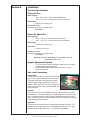
1
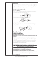
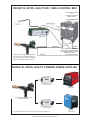
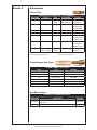
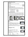
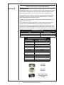
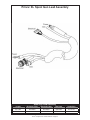
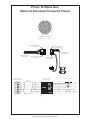
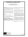
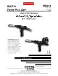
Prince® XL/Spool Gun Owner’s Manual Product: Prince® XL/ Spool Gun Manual: 091-0530 Serial: 03050001 Voltage Rating: 24 VDC Revision: April 2009 Rev D Gun models: 313-XXX 316-XXX 225 Ampere Push-Pull Welding Gun 255 Ampere Push-Pull Welding Gun Table of Contents Safety Considerations..........................................................................................i-vi Installation................................................................................................. Section A Technical Specifications.....................................................................................1 Support Equipment Required.............................................................................1 Gun Lead Connections......................................................................................1 Installing Spool Assembly..................................................................................2 Interconnections.................................................................................................3 Operation.................................................................................................. Section B General..............................................................................................................4 Barrels................................................................................................................4 Controls and Settings.........................................................................................4 Drive Roll and Idler Rolls....................................................................................5 Accessories...............................................................................................Section C Contact Tips ......................................................................................................6 Gas Cups...........................................................................................................6 Barrel Liners.......................................................................................................6 Barrel Assemblies..............................................................................................7 Optional Barrels.................................................................................................7. Optional Kits............................................................................................................7 Optional Accessories..........................................................................................8 Spool Gun Controls............................................................................................8 Maintenance.............................................................................................Section D Periodic Maintenance...........................................................................................10. Recommended Spare Parts List...........................................................................10 Troubleshooting........................................................................................ Section E Troubleshooting Guide.....................................................................................12 Testing the Gun................................................................................................13 Appendices............................................................................................... Section F Diagrams/Parts List..........................................................................................15 Safety Warnings Warranty Declaration of Conformity for European Community (CE) Products Note This information is provided for units with CE certification (see rating label on unit). Manufacturer’s Name: MK Products, Inc. 16882 Armstrong Ave. Irvine, CA 92606 Declares that the product: Prince® XL conforms to the following Directives and Standards: Directives Low Voltage Directive: 73/23/EEC Electromagnetic Compatibility (EMC) Directive: 89/336/EEC Standards Arc Welding Equipment Part I: Welding Power Sources: IEC 60974-1 (September 1998 - Second Edition) Arc Welding Equipment: Wirefeed Systems: IEC 974-5 (September 1997 - Draft Revision) Degrees of Protection Provided by Enclosures (IP Code): IEC 529:1989 (November 1989 - First Edition) Insulation Coordination For Equipment With Low-Voltage Systems: Part I: Principles, Requirements and Tests: IEC 664-1: 1992 (October 1992 - First Edition) Electromagnetic Compatibility, (EMC): EN 50199 (August 1995) Torches And Guns For Arc Welding, EN 50078 SAFETY CONSIDERATIONS ELECTRIC ARC WELDING EQUIPMENT CAUTION : READ BEFORE ATTEMPTING INSTALLATION, OPERATION OR MAINTENANCE OF THIS EQUIPMENT 1-1 INTRODUCTION This equipment is intended for ultimate application by commercial/industrial users and for operation by persons trained and experienced in the use and maintenance of welding equipment. Operation should not be undertaken without adequate training in the use of such equipment. Training is available from many public and private schools or similar facilities. Safe practices in the installation, operation and maintenance of this equipment requires proper training in the art, a careful study of the information provided with the equipment, and the use of common sense. Rules for safe use are generally provided by suppliers of welding power sources, compressed gas suppliers, and electrode suppliers. Careful compliance with these rules will promote safe use of this equipment. The following Safety Rules cover some of the more generally found situations. READ THEM CAREFULLY. In case of any doubt, obtain qualified help before proceeding. 1-2 GENERAL PRECAUTIONS A. Burn Prevention ELECTRIC ARC WELDING PRODUCES HIGH INTENSITY HEAT AND ULTRAVIOLET RADIANT ENERGY WHICH MAY CAUSE SERIOUS AND PERMANENT EYE DAMAGE AND WHICH MAY DAMAGE ANY EXPOSED SKIN AREAS. Wear helmet with safety goggles or glasses with side shields underneath, appropriate filter lenses or plates (protected by clear cover glass). This is a must for welding or cutting (and chipping) to protect the eyes from radiant energy and flying metal. Replace cover glass when broken, pitted, or spattered. Medical first aid and eye treatment. First aid facilities and a qualified first aid person should be available for each shift unless medical facilities are close by for immediate treatment of flash burns of the eyes and skin burns. Wear protective clothing - leather (or asbestos) gauntlet gloves, hat, and high safety-toe shoes. Button shirt collar and pocket flaps, and wear cuffless trousers to avoid entry of sparks and slag. Avoid oily or greasy clothing. A spark may ignite them. Flammable hair preparations should not be used by persons intending to weld or cut. Hot metal such as electrode stubs and work pieces should never be handled without gloves. Ear plugs should be worn when working on overhead or in a confined space. A hard hat should be worn when others work overhead. B. Toxic Fume Prevention WARNING: The use of this product may result in exposure to chemicals known to the State of California to cause cancer and birth defects or other reproductive harm. Adequate ventilation. Severe discomfort, illness or death can result from fumes, vapors, heat, or oxygen enrichment or depletion that welding (or cutting) may produce. Prevent them with adequate ventilation. NEVER ventilate with oxygen. Lead-, cadmium-, zinc-, mercury-, beryllium-bearing and similar materials, when welded or cut, may produce harmful concentrations of toxic fumes. Adequate local exhaust ventilation must be used, or each person in the area, as well as the operator, must wear an air-supplied respirator. For beryllium, both must be used. Metals coated with or containing materials that emit toxic fumes should not be heated unless coating is removed form the work surface, the area is well ventilated, or the operator wears an air-supplied respirator. Work in a confined space only while it is being ventilated and, if necessary, while wearing an air-supplied respirator. Gas leaks in a confined space should be avoided. Leaked gas in large quantities can change oxygen concentration dangerously. Do not bring gas cylinders into a confined space. Leaving confined space, shut OFF gas supply at source to prevent possible accumulation of gases in the space if downstream valves have been accidentally opened or left open. Check to be sure that the space is safe before reentering it. Vapors from chlorinated solvents can be decomposed by the heat of the arc (or flame) to form PHOSGENE, a highly toxic gas, and other lung and eye irritating products. The ultraviolet (radiant) energy of the arc can also decompose trichloroethylene and perchloroethylene vapors to form phosgene. DO NOT WELD or cut where solvent vapors can be drawn into the welding or cutting atmosphere or where the radiant energy can penetrate to atmospheres containing even minute amounts of trichloroethylene or perchloroethylene. Prince® XL/Spool Gun Owner's Manual - Page i C. Fire and Explosion Prevention Causes of fire and explosion are: combustibles reached by the arc, flame, flying sparks, hot slag, or heated material, misuse of compressed gases and cylinders, and short circuits. BE AWARE THAT flying sparks or falling slag can pass through cracks, along pipes, through windows or doors, and through wall or floor openings, out of sight of the goggled operator. Sparks can fly many feet. To prevent fires and explosion: Keep equipment clean and operable, free of oil, grease, and (in electrical parts) of metallic particles that can cause short circuits. If combustibles are in area, do NOT weld or cut. Move the work if practicable, to an area free of combustibles. Avoid paint spray rooms, dip tanks, storage areas, ventilators. If the work cannot be moved, move combustibles at least 35 feet away, out of reach of sparks and heat; or protect against ignition with suitable and snug-fitting, fire-resistant covers or shields. Walls touching combustibles on opposite sides should not be welded on (or cut). Walls, ceilings, and floor near work should be protected by heatresistant covers or shields. Fire watcher must be standing by with suitable fire extinguishing equipment during and for some time after welding or cutting if: 1. Appreciable combustibles (including building construction) are within 35 feet. 2. Appreciable combustibles are further than 35 feet, but can be ignited by sparks. 3. Openings (concealed or visible) in floors or walls within 35 feet may expose combustibles to sparks. 4. Combustibles adjacent to walls, ceilings, roofs, or metal partitions can be ignited by radiant or conducted heat. Hot work permit should be obtained before operation to ensure supervisor’s approval that adequate precautions have been taken. After work is done, check that area is free of sparks, glowing embers, and flames. An empty container that held combustibles, or that can produce flammable or toxic vapors when heated, must never be welded on or cut, unless container has first been cleaned in accordance with industry standards. This includes: a thorough steam or caustic cleaning (or a solvent of water washing, depending on the combustible’s solubility), followed by purging and inerting with nitrogen or carbon dioxide, and using protective equipment. Water-filling just below working level may substitute for inerting. A container with unknown contents should be cleaned (see paragraph above). Do NOT depend on sense of smell or sight to determine if it is safe to weld or cut. Hollow castings or containers must be vented before welding or cutting. They can explode. Explosive atmospheres. NEVER weld or cut where the air may contain flammable dust, gas, or liquid vapors (such as gasoline). D. Compressed Gas Equipment The safe handling of compressed gas equipment is detailed in numerous industry publications. The following general rules cover many of the most common situations. 1. Pressure Regulators Regulator relief valve is designed to protect only the regulator from overpressure; it is not intended to protect any downstream equipment. Provide such protection with one or more relief devices. Never connect a regulator to a cylinder containing gas other than that for which the regulator was designed. Remove faulty regulator from service immediately for repair (first close cylinder valve). The following symptoms indicate a faulty regulator: Leaks - if gas leaks externally. Excessive Creep - if delivery pressure continues to rise with downstream valve closed. Faulty Gauge - if gauge pointer does not move off stop pin when pressurized, nor returns to stop pin after pressure release. Repair. Do NOT attempt repair. Send faulty regulators for repair to manufacturer’s designated repair center, where special techniques and tools are used by trained personnel. 2. Cylinders Cylinders must be handled carefully to prevent leaks and damage to their walls, valves, or safety devices: Avoid electrical circuit contact with cylinders including third rails, electrical wires, or welding circuits. They can produced short circuit arcs that may lead to a serious accident. (See 1-3C) ICC or DOT marking must be on each cylinder. It is an assurance of safety when the cylinder is properly handled. Identifying gas content. Use only cylinders with name of gas marked on them; do not rely on color to identify gas content. Notify supplier if unmarked. NEVER DEFACE or alter name, number, or other markings on a cylinder. It is illegal and hazardous. that may clog orifices and damage seats before connecting regulator. Except for hydrogen, crack valve momentarily, pointing outlet away from people and sources of ignition. Wipe with a clean, lintless cloth. Empties: Keep valves closed, replace caps securely; mark MT; keep them separate from FULLS, and return promptly. Match regulator to cylinder. Before connecting, check that the regulator label and cylinder marking agree, and that the regulator inlet and cylinder outlet match. NEVER Connect a regulator designed for a particular gas or gases to a cylinder containing any other gas. Prohibited use. Never use a cylinder or its contents for other than its intended use, NEVER as a support or roller. Locate or secure cylinders so they cannot be knocked over. Passageways and work areas. Keep cylinders clear of areas where they may be stuck. Transporting cylinders. With a crane, use a secure support such as a platform or cradle. Do NOT lift cylinders off the ground by their valves or caps, or by chains, slings, or magnets. Do NOT expose cylinders to excessive heat, sparks, slag, and flame, etc. that may cause rupture. Do not allow contents to exceed 55 degrees C (130 degrees F.) Cool with water spray where such exposure exists. Protect cylinders, particularly valves from bumps, falls, falling objects, and weather. Replace caps securely when moving cylinders. Stuck valve. Do NOT use a hammer or wrench to open a cylinder valve that cannot be opened by hand. Notify your supplier. Mixing gases. NEVER try to mix any gases in a cylinder. NEVER refill any cylinder. Cylinder fittings should never be modified or exchanged. 3. Hose Prohibited use. Never use hose other than that designed for the specified gas. A general hose identification rule is: red for fuel gas, green for oxygen, and black for inert gases. Use ferrules or clamps designed for the hose (not ordinary wire or other substitute) as a binding to connect hoses to fittings. No copper tubing splices. Use only standard brass fittings to splice hose. Avoid long runs to prevent kinks and abuse. Suspend hose off ground to keep it from being run over, stepped on, or otherwise damaged. Coil excess hose to prevent kinks and tangles. Tighten connections. When assembling threaded connections, clean and smooth seats where necessary. Tighten. If connection leaks, disassemble, clean, and retighten, using properly fitting wrench. Adapters. Use a CGA adapter (available from your supplier) between cylinder and regulator, if one is required. Use two wrenches to tighten adapter marked RIGHT and LEFT HAND threads. Regulator outlet (or hose) connections may be identified by right hand threads for oxygen and left hand threads (with grooved hex on nut or shank) for fuel gas. 5. Pressurizing Steps: Drain regulator of residual gas through suitable vent before opening cylinder (or manifold valve) by turning adjusting screw in (clockwise). Draining prevents excessive compression heat at high pressure seat by allowing seat to open on pressurization. Leave adjusting screw engaged slightly on single-stage regulators. Stand to side of regulator while opening cylinder valve. Open cylinder valve slowly so that regulator pressure increases slowly. When gauge is pressurized (gauge reaches regulator maximum) leave cylinder valve in following position: for oxygen and inert gases, open fully to seal stem against possible leak; for fuel gas, open to less than one turn to permit quick emergency shut-off. Use pressure charts (available from your supplier) for safe and efficient recommended pressure settings on regulators. Check for leaks on first pressurization and regularly thereafter. Brush with soap solution. Bubbles indicate leaks. Clean off soapy water after test; dried soap is combustible. Protect hose from damage by sharp edges, and by sparks, slag, and open flame. E. User Responsibilities Examine hose regularly for leaks, wear, and loose connections. Immerse pressured hose in water; bubbles indicate leaks Remove leaky or defective equipment from service immediately for repair. Read and follow user manual instructions. Repair leaky or worn hose by cutting area out and splicing. Do NOT use tape. F. Leaving Equipment Unattended 4. Proper Connections Clean cylinder valve outlet of impurities Follow all Safety Rules. Close gas supply at source and drain gas. Prince® XL/Spool Gun Owner's Manual - Page ii G. Rope Staging-Support Rope staging-support should not be used for welding or cutting operation; rope may burn. 1-3 ARC WELDING Comply with precautions in 1-1, 1-2, and this section. Arc Welding, properly done, is a safe process, but a careless operator invites trouble. The equipment carries high currents at significant voltages. The arc is very bright and hot. Sparks fly, fumes rise, ultraviolet and infrared energy radiates, weldments are hot, and compressed gases may be used. The wise operator avoids unnecessary risks and protects himself and others from accidents. A. Burn Protection Comply with precautions in 1-2. The welding arc is intense and visibly bright. Its radiation can damage eyes, penetrate lightweight clothing, reflect from light-colored surfaces, and burn the skin and eyes. Skin burns resemble acute sunburn; those from gas-shielded arcs are more severe and painful. DON’T GET BURNED; COMPLY WITH PRECAUTIONS. 1. Protective Clothing Wear long-sleeve clothing in addition to gloves, hat, and shoes. As necessary, use additional protective clothing such as leather jacket or sleeves, flameproof apron, and fire-resistant leggings. Avoid outer garments of untreated cotton. Bare skin protection. Wear dark, substantial clothing. Button collar to protect chest and neck, and button pockets to prevent entry of sparks. 2. Eye and Head Protection Protect eyes from exposure to arc. Eyes may be damaged by radiant energy when exposed to the electric arc, even when not looking in the direction of the arc. Never look at an electric arc without protection. Welding helmet or shield containing a filter plate shade no. 12 or denser must be used when welding. Place over face before striking arc. Protect filter plate with a clear cover plate. Cracked or broken helmet or shield should NOT be worn; radiation can be passed through to cause burns. Cracked, broken, or loose filter plates must be replaced IMMEDIATELY. Replace clear cover plate when broken, pitted, or spattered. Flash goggles with side shields MUST be worn under the helmet to give some protection to the eyes should the helmet not be lowered over the face before an arc is struck. Looking at an arc momentarily with unprotected eyes (particularly a high intensity gasshielded arc) can cause a retinal burn that may leave a permanent dark area in the field of vision. 3. Protection of Nearby Personnel Enclose the welding area. For production welding, a separate room or enclosed bay is best. In open areas, surround the operation with low-reflective, noncombustible screens or panels. Allow for free air circulation, particularly at floor level. Viewing the weld. Provide face shields for all persons who will be looking directly at the weld. Others working in area. See that all persons are wearing flash goggles. Before starting to weld, make sure that screen flaps or bay doors are closed. B. Toxic Fume Prevention Comply with precautions in 1-2B. Generator engine exhaust must be vented to the outside air. Carbon monoxide can kill. C. Fire and Explosion Prevention Comply with precautions in 1-2C. Equipment’s rated capacity. Do not overload arc welding equipment. It may overheat cables and cause a fire. Loose cable connections may overheat or flash and cause afire. Never strike an arc on a cylinder or other pressure vessel. It creates a brittle area that can cause a violent rupture or lead to such a rupture later under rough handling. D. Compressed Gas Equipment Comply with precautions in 1-2D. E. Shock Prevention Exposed electrically hot conductors or other bare metal in the welding circuit, or in ungrounded, electrically-HOT equipment can fatally shock a person whose body becomes a conductor. DO NOT STAND, SIT, LIE, LEAN ON, OR TOUCH a wet surface when welding without suitable protection. To protect against shock: Keep body and clothing dry. Never work in damp area without adequate insulation against electrical shock. Stay on a dry duckboard, or rubber mat when dampness or sweat cannot be avoided. Sweat, sea water, or moisture between body and an electrically HOT part - or grounded metal - reduces the body surface electrical resistance, enabling dangerous and possibly lethal currents to flow through the body. 1. Grounding the Equipment When installing, connect the frames of each unit such as welding power source, control, work table, and water circulator to the building ground. Conductors must be adequate to carry ground currents safely. Equipment made electrically HOT by stray currents may shock, possibly fatally. Do NOT GROUND to electrical conduit, or to a pipe carrying ANY gas or a flammable liquid such as oil or fuel. Three-phase connection. Check phase requirement of equipment before installing. If only three-phase power is available, connect single-phase equipment to only two wires of the three-phase line. Do NOT connect the equipment ground lead to the third (live) wire, or the equipment will become electrically HOT - a dangerous condition that can shock, possibly fatally. Before welding, check ground for continuity. Be sure conductors are touching bare metal of equipment frames at connections. If a line cord with a ground lead is provided with the equipment for connection to a switch box, connect the ground lead to the grounded switch box. If a three-prong plug is added for connection to a grounded mating receptacle, the ground lead must be connected to the ground prong only. If the line cord comes with a three-prong plug, connect to a grounded mating receptacle. Never remove the ground prong from a plug, or use a plug with a broken ground prong. 2. Connectors Fully insulated lock-type connectors should be used to join welding cable lengths. 3. Cables Frequently inspect cables for wear, cracks, and damage. IMMEDIATELY REPLACE those with excessively worn or damaged insulation to avoid possibly lethal shock from bared cable. Cables with damaged areas may be taped to give resistance equivalent to original cable. Keep cable dry, free of oil and grease, and protected from hot metal and sparks. 4. Terminals and Other Exposed Parts Terminals and other exposed parts of electrical units should have insulating covers secured before operation. 5. Electrode Wire Electrode wire becomes electrically HOT when the power switch of gas metal-arc welding equipment is ON and welding gun trigger is pressed. Keep hands and body clear of wire and other HOT parts. 6. Safety Devices Safety devices such as interlocks and circuit breakers should not be disconnected or shunted out. Before installation, inspection, or service of equipment, shut OFF all power, and remove line fuses (or lock or red-tag switches) to prevent accidental turning ON of power. Disconnect all cables from welding power source, and pull all 115 volts line-cord plugs. Do not open power circuit or change polarity while welding. If, in an emergency, it must be disconnected, guard against shock burns or flash from switch arcing. Leaving equipment unattended. Always shut OFF, and disconnect all power to equipment. Power disconnect switch must be available near the welding power source. Prince® XL/Spool Gun Owner's Manual - Page iii Thank You For selecting a quality product. We want you to take pride in operating this product...as much pride as we have in bringing the product to you! Please Examine Carton and Equipment For Damage Immediately When this equipment is shipped, title passes to the purchaser upon receipt by the carrier. Consequently, claims for material damaged in shipment must be made by the purchaser against the transportation company at the time the shipment is received. Please record your equipment identification information below for future reference. This information can be found on your machine nameplate. Model Name & Number _____________________ Code & Serial Number _____________________ Date of Purchase _____________________ Whenever you request replacements parts for, or information on this equipment always supply the information you have recorded above. Read this Owner’s Manual completely before attempting to use this equipment. Save this manual and keep it handy for quick reference. Pay particular attention to the safety instructions we have provided for your protection. Section A Installation Technical Specifications Prince® XL Gun Wire Capacity • .030” -.045” (0.6 - 1.2mm) solid and hard wire • .030” - 1/16” (0.8 - 1.6mm) aluminum and cored wire Wire Speed • 800 ipm (20.3 mpm) max. Duty Cycle - 60% All ratings are at 25V using Argon Gas • 225 Amps Prince® XL Spool Gun Wire Capacity • .030” - .045” (0.6 - 1.2mm) solid and hard wire • .030” - 1/16” (0.8 - 1.6mm) aluminum and cored wire Wire Speed* • 900 ipm (22.9 mpm) max. Spool Size • 4 inches (101.6mm) Duty Cycle - 60% All ratings are at 25V using Argon Gas • 255 Amps *Maximum ipm varies depending on input voltage, wire size and the control box used. Support Equipment Required • • • CV or CC power source of sufficient capacity for your needs. Regulated gas supply and hoses. Properly sized power leads from power source to wire feeder and ground. Gun Lead Connections Power Cable A #2 AWG power cable is used on the Prince® XL gun. The gun end is threaded into the gun body. The power cable fitting connects to the power manifold when using a Cobramatic® wire feed cabinet. When the Prince® XL is purchased as a spool gun; the power cable comes standard with a lug connector. Conduit The Prince® XL gun comes standard with a poly-lined conduit for running aluminum wire. The longer fitting with a shallow groove is used on the gun end. A setscrew located on top of the gun handle secures the conduit in place. A small spool liner (P/N 003-0198) is used on the spool gun and held in place by the same setscrew. Gas Hose The gas hose is secured over the barbed gas fitting with a tie wrap. The cabinet end of the gas hose uses our standard gas fitting (1/8” - 27 nps), whereas the spool gun uses a 5/8” - 18 IAA RH male gas fitting. Prince® XL/Spool Gun Owner's Manual - Page 1 Electric Cable A seven-conductor control cable is used on the Prince® XL gun. The gun end of the control cable is secured to the gun with a boot clamp and plugged into the pot assembly and micro switch connectors. Slack is left in the electric cable as it exits the back of the gun to prevent cable breakage. The cabinet end has a seven-pin “W” clocked amphenol connector. Installing Spool Assembly (Kit P/N 005-0632) Loosen the screw that secures the conduit through access hole located on top right rear handle with a 1/16” Allen wrench. Conduit Securing Screw Remove conduit by pulling it out of the back of the gun. E-Ring Rear Wire Guide Spool Liner Install spool liner, and secure with screw. Remove both rear handle screws, and secure spool canister with longer screws provided. 2 Screws Spool Gun Setup Loading Electrode Wire Unscrew, and remove spool cover. Apply tension to drive rolls, so the wire will be picked up and fed through the contact tip. Straighten out the first six inches of wire and push it through the liner. Jog the trigger until the wire is picked up by drive rolls and fed through the contact tip. Hold the brake assembly back towards the top of the gun; load the spool onto shaft with the wire coming off the bottom of the spool. Release the brake assembly to rest on the wire surface. Replace the spool cover; making sure that the opening is over liner. Note: The brake assembly is designed to automatically control spool drag and keep the wire from jumping off the spool. Disassembly of Prince® XL/Spool Gun Remove the trigger pin with punch and remove the trigger. Remove the six (6) handle screws and the spool adapter if installed. Remove the barrel from the gun, loosen the barrel taper lock assembly and slide towards the cup. Leave the barrel inserted in gun the body. Pull the handles apart. Prince® XL/Spool Gun Owner's Manual - Page 2 ® PRINCE XL SPOOL GUN TO WC-1 WELD CONTROL BOX CONSTANT VOLTAGE OR CONSTANT CURRENT POWER SUPPLY WC-1 CONSTANT CURRENT POSA START SENSING LEADS NOT NEEDED WITH CONSTANT VOLTAGE SUPPLIES NOTE: The Posa Start feature permits the WC-1 to be used in combination with any Constant Current DC power source with an open circuit voltage in excess of 55 volts. TO CUSTOMER GAS SUPPLY PRINCE XL SPOOL GUN TO COMMON POWER SUPPLIES* ® PA-L 1 Spool Gun Adapter 14-Pin C/D Trigger V350 PRO 120VAC Output Power Cable and Gas Hose must also be connected PA-M 1 Spool Gun Adapter 14-Pin A/B Trigger * For more power supply options, see Spool Gun Controls in Section C Prince® XL/Spool Gun Owner's Manual - Page 3 XMT 304 120VAC Output Section B Operation General Description The Prince® XL gun was specifically designed to operate as both a push-pull gun and spool gun. The 24 volt DC gun motor is controlled by a 3-3/4 turn potentiometer recessed in the pistol grip. The gun trigger is so designed that when it is partially depressed, gas flow starts via the valve located in the gun body - prior to ignition of the arc. When the trigger is partially released after welding (extinguishing the arc), gas flow continues until the trigger is fully released. Built-in pre and post gas flow. The gas cups and contact tips used on the Prince® XL air cooled barrel are the same as those used on the Cobra Gooseneck. The drive and idler rolls are also the same as on the Cobra Gooseneck. The modular design allows parts to be replaced in sub assemblies for minimum spare parts inventory and less down time. Barrels The Prince® XL comes standard with a straight barrel assembly. An optional curved barrel assembly (P/N 003-2152) is also available. In cases where these barrels need to be extended or the tip threads have been damaged, a tip extender (P/N 621-0424) can be adapted. The same tips and threads can be used, however a longer Teflon liner (P/N 931-0137) is required. Barrel Removal and Installation To remove a barrel assembly, loosen the patented EZ Lock® taper lock nut assembly 3/4 to 1 turn. This will push barrel away from the body far enough so that it may be pulled out of the body. To replace a barrel assembly, push the barrel assembly into the gun body until it clicks to a stop. To assure proper seating of the barrel, open the drive/idler roll door in the top of the handle. The rear face of the barrel should now be flush with the gun body. Take care not to damage the “O” rings when inserting into the body. Tighten taper lock nut assembly firmly so that barrel cannot rotate. Barrel Rotation To rotate a barrel assembly, loosen the patented EZ Lock® taper lock nut assembly no more than 1 turn. Rotate barrel to the position of your choice and retighten taper lock nut assembly firmly so that the barrel cannot rotate. WARNING: Do not attempt to weld without the barrel being tightly secured in the gun body, or damage to the barrel or body may result. Failure to take such precaution will void your warranty. Controls and Settings Potentiometer The potentiometer is located in the bottom of the pistol grip and provides 3-3/4 turns of adjustment for up to 800 ipm. The potentiometer is mounted to one side of a PC board and is held in place by a support plate. Both the potentiometer and the support plate have slots that locate and secure the potentiometer in the handle. The other side of the PC board houses the motor connectors and ribbon cable. Locking disks behind the potentiometer knob provides a stop at the minimum and maximum potentiometer settings. Micro Switch The micro switch assembly (P/N 003-0568) consists of the micro switch, leads, and connector. The assembly is secured to the gun block with two (2) screws. An insulator between the gun block and micro switch prevents Prince® XL/Spool Gun Owner's Manual - Page 4 accidental shorting of the switch leads. The leads are laid in the channel under the motor and held in place with electrical tape. Drive and Idler Rolls The Prince® XL gun comes standard with a knurled drive roll and a grooved idler roll, which will handle both steel and aluminum wire with diameters from .030-1/16 inch. Optional insulated V-groove drive rolls are also available for aluminum wire if desired (see Optional Kits). Drive roll tension is accomplished by means of a pressure adjusting allen screw located on the left hand side of the gun. Proper tension is achieved when wire does not slip if a small amount of pressure is added to the wire as it exits the tip. NOTE: Over-tightening of the drive rolls will cause excessive knurling and/or deformation of the wire. Drive Roll Installation/Removal NOTE: Neither of the handles needs to be removed to access the drive or idler rolls 1.Pull the Cam Lever away from the idler roll. This will relieve the pressure against the drive roll. 2. Align the Drive Roll Removal Tool (P/N 931-0100) over the flats of the drive roll. Hold the gun with one hand or on a table top, with the other hand give the Removal Tool a quick snap-turn in the CLOCKWISE DIRECTION. 3. Once the drive roll is loose, continue to spin drive roll in the clockwise direction to remove the drive roll from the gun. 4. Install a new drive roll on the left-hand threaded shaft. The drive roll will self-tighten when it is feeding wire. Idler Roll Installation and Removal 1. Using a slot type screwdriver, loosen idler screw, taking care not to lose lock washer under idler roll. 2. Insert new idler roll and lock washer onto screw, insuring that idler groove is toward top and lock washer is beneath. 3. Tighten. Groove Towards Top Idler Arm Lock Washer NOTE: Lock washer must be under idler roll or it will not turn freely. Prince® XL/Spool Gun Owner's Manual - Page 5 Section C Accessories Contact Tips Wire Size Heavy Duty Contact Tip - 3/8" Diameter* Tip ID Arc Tip Length .030” (0.8mm) .040” (1.0mm) .035” (0.9mm) .045” (1.1mm) Spray Short Spray 1.57” (39.9mm) 1.82” (46.2mm) 1.57” (39.9mm) .035" (0.9mm) .045" (1.1mm) .045" (1.1mm) .054" (1.37mm) 3/64” (1.2mm) .054” (1.37mm) Short Short Spray 1.82” (46.2mm) 1.82” (46.2mm) 1.57” (39.9mm) Part No. 621-0390-25 621-0396-25 621-0391-25 621-0391-250† 621-0391-500†† 621-0397-25 621-0398-25 621-0392-25 621-0392-250† 3/64” (1.2mm) .060” (1.5mm) Spray 1.57” (39.9mm) 1/16” (1.6mm) .074” (1.9mm) .085” (2.16mm) Spray Spray 1.57” (39.9mm) *Use of tip removal tool is recommended **This size tip furnished with gun † 621-0392-500†† 621-0393-25** 621-0393-250† 621-0393-500†† 621-0394-25 621-0395-25 Also sold in quantities of 250 Also sold in quantities of 500 †† Finned Copper Gas Cups Tip Extender Finned Copper Gas Cups Size I.D. Part No. 6 3/8” (9.5mm) 621-0248 8 1/2” (12.7mm) 621-0249 10 5/8” (15.8mm) 621-0250* 10 H.D. 5/8” (15.8mm) 621-0251 12 H.D. 3/4” (19.0mm) 621-0252 N/A Tip Extender 621-0424 *Standard - furnished with gun Gun Barrel Liners Prince® XL Gun Barrel Liners Barrel P/N 003-2152 -- Description Part No. Curved, air cooled, steel wire only .030”-.065” (.8-1.6mm) 615-0343 Teflon liner package, 5 pieces 931-0137 Prince® XL/Spool Gun Owner's Manual - Page 6 Barrel Assemblies Standard 003-2151 225 Amp, Air Cooled Standard 003-2152 225 Amp, Air Cooled Optional 6”, 12” and 18” Straight and Curved Barrel Assemblies 6” Straight Air Cooled Barrel Assembly.............................................. 003-2151 6” Curved 45° Air Cooled Barrel Assembly......................................... 003-2152 12” Straight Air Cooled Barrel Assembly ........................................... 003-2332 12” Curved Air Cooled Barrel Assembly............................................. 003-2333 18” Straight Air Cooled....................................................................... 003-2334 18” 45° Air Cooled.............................................................................. 003-2335 Optional Kits Insulated drive roll kits are used to prevent preheating of the wire which may soften it and clog the liner. This picking up of current at the drive rolls rather than at the contact tip is usually not a problem unless using too large of a contact tip or excessively oxidized aluminum wire. Insulated Groove Drive Roll Kit....................................................... 005-0640 For .030" (0.8mm) dia. aluminum wire. Includes insulated groove drive roll and insulated idler roll assy. Insulated Groove Drive Roll Kit....................................................... 005-0716 For .035" (0.9mm) dia. aluminum wire. Includes insulated groove drive roll and insulated idler roll assy. Insulated Groove Drive Roll Kit....................................................... 005-0717 For .040" (1.0mm)dia. aluminum wire. Includes insulated groove drive roll and insulated idler roll assy. Insulated Groove Drive Roll Kit....................................................... 005-0718 For .045" (1.2mm) dia. aluminum wire. Includes insulated groove drive roll and insulated idler roll assy. Insulated Groove Drive Roll Kit....................................................... 005-0644 For .062" (1.6mm) dia. aluminum wire. Includes insulated groove drive roll and insulated idler roll assy. Prince® XL Handle Kit....................................................................... 005-0633 Includes left and right handle with door, trigger and pin,and all handle screws. Spool Adapter Kit............................................................................. 005-0632 Includes left and right handle with door, trigger and pin, and all handle screws. Used to change a standard 313-xxx series Prince® XL gun into a spool gun. Barrel Insulator Kit........................................................................... 005-0696 Heavy Duty Spool Gun Brake Spring for Hardwires..................... 005-0682 25’ 7 Pin Amphenol Extension Cable.............................................. 005-0660 Used to extend the spool gun. Two cables may be joined together for 50’ extension. Power & gas cables not included. Prince® XL/Spool Gun Owner's Manual - Page 7 Optional Accessories Conduits Flat Spiral Steel Conduit for steel and cored wire 15ft./4.5m............................................................................................ 615-0208 25ft./7.6m............................................................................................ 615-0216 35ft./10.7m.......................................................................................... 615-0218 50ft./15.2m.......................................................................................... 615-0219 Snake Skin Zipper Cover Leather Snake Skin protective covers are now standard on all guns. You may order replacement covers to protect the lead assembly of the gun when the original factory cover becomes damaged or worn. The Velcro® closure makes it easy to replace in the field. 13' cover fits 15' lead............... 931-0110 23' cover fits 25' lead............... 931-0122 33’ cover fits 35’ lead............... 931-0132 48’ cover fits 50’ lead............... 931-0123 Gas Valve Removal Tool Gas valve removal is performed by using P/N 931-0105 Gas Valve Removal Tool. This multifunctional tool has been slotted on one side to encompass and conform to the gas valve stem and seat into the slotted gas valve body as seen in Figures 1 and 2. Removal of the gas valve can be accomplished by turning the gas valve tool counter clockwise. Reinstall by turning clockwise. The tool doubles as a bottle opener. Gas Valve Removal Tool Figure 1 Figure 2 Prince® XL Spool Gun Controls WC-1 P/N 001-3062 The WC-1 is desinged to hookup to any CV or CC power supply having its own contactor. CC Posa Start “run-in speed” is included as a standard feature. The control operates on 115VAC, 50-60hz power. For machines such as gas drives that do not have contactors, the MK200 Contactor Box (P/N 001-3066) must be used. WC-1 MK200 Contactor Box P/N 001-3066 MK200 Contactor Box PA-L1 Spool Gun Control - Lincoln P/N 005-0676 Connects directly to Lincoln Electric power supplies (42V system) with 14-Pin (X-clocked) amphenol connectors, such as: CV 250 CV 655 DC 655 Range 275 CV 300 DC 400 V350-Pro (factory model) Ranger 305G CV 400 DC 600 Ranger 250 Prince® XL/Spool Gun Owner's Manual - Page 8 Spool Gun Control - Lincoln PA-M1 Spool Gun Control - Miller P/N 005-0261 Connects directly to Miller power supplies (24V system) that are classified with 14-Pin amphenols as type 6 or 9 and to Thermal Arc units, such as: MILLER SUPPLIES Millermatic 200 Deltaweld's Shopmaster CP Series XMT's & Maxtron Trailblazer 250, 251 Regency's Spool Gun Control - Miller THERMAL ARC Thermal Arc 300GMS CC/CV Fabricator 210, 250, 300 LF Any Gas-drive that has a CV tap and contactor installed with a 14 pin amphenol. PA-G1 Spool Gun Control - Generic P/N 005-0264 This Generic Torpedo is designed to hook-up to CV power supplies that supply an auxiliary 26 VAC @ 1.7 amps and uses a closing contact signal. The unit is supplied with bare wires that must be connected to the power supply. Some examples of power supplies that can be hooked-up are: Spool Gun Control - Generic Lincoln SP-250, 255 & Wirematic 250 & 255 Beta-Mig 200 & Beta-Mig LF Airco Dip-Pak 200, 225 & 250 ESAB (L-TEC) / MigMaster 250 P/N 005-0206 An amphenol adaptor cable and gas/power lug are all that is needed to connect to the Migmaster. Adaptor kit includes everything needed. ESAB (L-Tec-Linde) MigMaster 250 MillerMatic 250 & Vintage / Hobarts BetaMig 2510 P/N 005-0205 This easy to install, plug in module fits the Millermatic 250, Miller Vintage machine, or Hobart Betamig 2510. It and a Prince® Spool Gun are all that is needed to get your customer up and running. MillerMatic 250, Vintage and BetaMig 2510 Panasonic Gunslinger 260 P/N 005-0617 Easy to install adapter cable using Gunslinger speed control. Panasonic Gunslinger 260 ESAB MigMaster 251 P/N 005-0624 A panel kit plugs directly into the front of the MigMaster 251 and includes everything that is needed to interface the spool gun. ESAB MigMaster 251 MillerMatic 250X/251 P/N 005-0629 Easy to install adapter cable using MillerMatic 250X speed control. Reference Tech Bulletin TB 2112 found at mkproducts.com for Millermatic/Prince XL spool gun compatibility. MillerMatic 250X & Fabricator 250 Fabricator 250 P/N 005-0689 Easy to install adapter cable using Thermal Arc Fabricator 250. Prince® XL/Spool Gun Owner's Manual - Page 9 NOTE: For further information on spool gun adaptability, see the weld control selector guide or contact MK Products. Section D Maintenance Maintenance of the gun will normally consist of a general cleaning of the wire guide system, including tubes, drive rolls, and conduit at regular intervals. Remove spatter build-up from inside of nozzles with a hardwood stick. The only parts on the gun that are subject to normal wear are the conduit, contact tips, gas cups, drive and idler rolls and barrel liners. A supply of those parts should be maintained on hand. If repairs do become necessary, qualified shop maintenance personnel can easily replace any parts. Your Cobramatic® system is designed to provide years of reliable service. Normal wear and component failure may require occasional service. The number of units in operation and the importance of minimal “down time” will determine to what extent spare parts should be stocked on hand. See the “Recommended Spart Parts List” for the mose commonly replaced parts. Maintenance Tools Tool Part Number Gas Valve Removal Tool Contact Tip Removal Tool Drive Roll Removal Tool 931-0105 931-0002 931-0100 Recommended Spart Parts List Part Number Description 615-0601-15 615-0601-25 615-0601-35 615-0601-50 005-0661 003-0568 005-0633 511-0101 005-0686 325-0206 333-0082 003-0585 431-3117 003-0198 003-2072 003-2071 Conduit 15’ Conduit 25’ Conduit 35’ Conduit 50’ Potentiometer Kit Micro Switch Handle Kit Drive Roll Idler Roll Kit Idler Roll Screw Idler Roll Washer Trigger Assy Door Wire Guide-Spool Gun Brake Assy - Spool Gun Cover Assy - Spool Gun Idler Roll 005-0686 Drive Roll 511-0101 Micro Switch Assy (switch with leads) 003-0568 Prince® XL/Spool Gun Owner's Manual - Page 10 Section E Troubleshooting All MK Products push-pull guns operate on the same principle. The 115 VAC or 42VAC slave motor in the feeder runs at a fast, constant speed, but has very low torque; it is always trying to feed more wire than the gun motor wants, and when the gun motor gets all it wants, it slows the slave motor, preventing a bird’s nest. Because of the low torque produced by the slave motor, a brake system is used to prevent wire overrun rather than tension. The drag adjustment in the spindle is used simply to keep the wire slightly taut, so it will not unspool while feeding wire. The 24 VDC gun motor is controlled by a solid state speed control and a pot located in the gun. The gun motor, potentiometer, and micro switch are connected to the cabinet/control box via a control cable and an amphenol connector. If this cable becomes damaged, a variety of symptoms can occur, depending on which wire(s) break. To test, check each wire for continuity and shorts. With the increased torque rating in the current Prince® XL motor, P/N 2110071, it now draws about twice as much current on start-up as the original Prince® motors P/N’s 211-0054 & 211-0056. Even though the duration of start-up is very short, about 15msec, it is too much for the standard 2A fuse to handle. For this reason, all 2A fuses in the motor circuitry (F1) should be changed to a 3AG 4A fast blow 250V fuse, P/N 151-0043. This new 4A fuse is sufficient for use on all model welding guns on the wire feeders, while still providing protection for the circuitry from any shorts in the motor or motor leads. This fuse change includes all Cobramatic, Cobramatic II and CobraMig 250/260, WC-1, Torpedo’s, and any other motor circuits powering Prince® XL or Spool Guns using motor P/N 211-0071. Remember the micro switch in the gun activates both the 115 VAC or 42 VAC and 24 VDC circuits in the cabinet. Therefore, if the slave motor and brake solenoid operate, but the gun does not, look more toward the 24 VDC circuits, speed control, control cable, or the gun motor. If nothing operates, look more toward the 115 VAC or 42 VAC input, micro switch leads, or micro switch. Prince® XL/Spool Gun Owner's Manual - Page 11 Troubleshooting Guide Trouble No wire feed at gun, feeder not operating, i.e. no slave motor or brake solenoid No wire feed at gun, feeder operating properly. Wire feeds, but welding wire is not energized. Remedy Cause 115/42 VAC control fuse in feeder. Replace fuse. Micro-switch defective/ not being activated. Replace switch. Check switch for operation. Broken electrical cable. Check micro-switch wires for continuity. 4 amp fuse (F1) in feeder/Control box blown. Check motor leads for shorts, then replace fuse. Bad potentiometer. Check potentiometer with meter. Broken electrical cable. Check motor and potentiometer wires for continuity. Bad speed control/PCB. See specific cabinet/control box owners manual for speed control operation. Loose or no cable connections. Check all power connections. Contactor control cable loose or in wrong position. Check power supply owners manual for location and type of contactor signal required, i.e., closing or 115 VAC. Welding power source. Check power source manual. Dirty or worn conduit. Blow out or replace conduit. Incorrect pressure on drive rolls. Adjust pressure at both feeder and gun. Idler roll stuck. Check for lock washer under idler roll, or replace if damaged. Wrong size contact tip. See contact tip table. Bad potentiometer. Check with meter. Broken electrical cable. Check potentiometer wires for continuity or short. Bad speed control See specific cabinet/control owners manual for speed control operation. Idler roll upside-down. Place groove in idler roll toward top. Rear wire guide missing. Replace wire guide. Incorrect placement of barrel insulator. To replace a barrel assembly, push the barrel assembly into the gun body until it clicks to a stop. To assure proper seating of the barrel, open the drive/idler roll door in the top of the handle. the rear face of the barrel should now be flush with the gun body. Wire feeds erratically. Wire feeds one speed only. Wire walks out of drive rolls. Poor gas/water flow. Prince® XL/Spool Gun Owner's Manual - Page 12 Testing The Gun Motor Check Remove the gun connector from the cabinet. Using the gun Amphenol, check the resistance across pins “A” and “B” (motor leads). The resistance across the motor should be between 5-10 ohms. If an open circuit or short exist, check the motor leads and motor independently. Testing the Potentiometer Using the gun Amphenol, check the resistance across pin “D” (wiper) and pin “C”. The resistance should vary from 0 - 5K ohms. Check the resistance across pin “D” (wiper) and pin “G”. The resistance should vary from 5K - 0 ohms. Testing the Micro Switch Using the gun Amphenol, check for continuity across pins “E” and “F” when the trigger is pressed. E F D G A C B "W" Clocked Amphenol Connector Viewed from front of connector Prince® XL/Spool Gun Owner's Manual - Page 13 THIS PAGE INTENTIONALLY BLANK Section F Prince® XL/Spool Gun Diagrams/Parts List Exploded View...........................................................................16 Head Body, Exploded View........................................................17 Spool Gun, Exploded View........................................................18 Straight Barrel Assembly............................................................19 Curved Barrel Assembly............................................................20 Spool Assembly, Exploded View................................................21 Lead Assembly...........................................................................22 Spool Gun Lead Assembly.........................................................23 Electrical.....................................................................................24 Prince® XL/Spool Gun Owner's Manual - Page 15 Part No. 001-1143 001-1144 001-1276 001-1145 Prince® XL/Spool Gun Owner's Manual - Page 16 Description 15ft 25ft 35ft 50ft Lead Assembly No. Qty. 1 1 1 1 1 2 3 4 5 6 7 8 9 10 11 12 13 14 15 16 17 18 19 20 21 22 23 24 25 26 27 1 1 1 1 1 1 7 1 1 1 3 4 2 2 2 2 1 1 1 1 1 1 1 1 1 1 1 1 No. Qty. 437-0237 Spacer Handle PXL 511-0101 Drive Roll Gold 751-0020 Cap Plug 0.218 ID x 0.50 LG Assy Potentiometer PXL Assy Trigger PXL Assy Body PXL Clamp Leads PXL Assy Barrel Str A/W PXL Pin Connector Molex 2 Pos Connector Molex 5 Pos Motor Screw Shc 4-40 x 0.50 Wshr Spr Lk #4 Wshr Spr Lk #6 Screw Pnhd Ph 4-40 x 0.625 St Screw Pnhd Ph 4-40 x 1.50 St Screw Pnhd Ph 6-32 x 1.50 Label Serial Number Tie Wrap Pin Dowel 0.093 x 2.00 LG Pin Dowel 0.093 x 1.25 LD Door PXL Spring Door PXL Handle Kit: Includes line items 005-0633 3,12,13,14,15,16,20,23,24,25 Lead Description Exploded View Part No. REF TABLE 005-0661 003-0585 003-1972 003-1974 003-2151 153-0852 153-0856 153-0857 211-0071 328-0003 333-0003 333-0005 336-0049 336-0056 336-0070 405-0706 411-0045 421-0408 421-0409 431-3117 435-3124 Prince® XL Exploded View Prince XL/Spool Gun Head Body, Exploded View P/N 003-1972 ® APPLY PIPE SEALANT TO MALE PIPE THREADS Note: If Cobramatic Wire Feeder is equipped with a gas solenoid kit, a modified gas valve stem (p/n 431-1080) must be installed in gun to allow gas flow from cabinet valve. Head Body Items #2, 5, & 11 can be purchased as a kit, P/N 005-0686 No. Qty. Part No. Description 1 1 431-2013 Wire Guide 2 1 333-0082 Washer, #10 Split Lock 3 1 419-0020 Spr. Comp., 0.29 OD x 0.047 4 1 321-1074 Set Screw, Mod 6-32 x 1/2 5 1 325-0206 Scr, Pnh, Sltd, 10-24 x 3/8 6 -7 -8 1 431-1427 Pin, Pivot 9 1 421-0129 Pin, Spring, 0.063 x 0.437 10 1 003-0568 Micro Switch Assy 11 1 511-0001 Idler Roll, Cobra 12 1 431-1424 Idler Arm 13 1 001-0562 Gas Valve, Cobra 14 2 431-1886 Ftg, 3/16 Hose, 1/16-27NPT 15 1 313-0008 E-ring, Int 0.188 16 --17 -Not Available Separately 18 1 002-0583 Adjust Screw, Idler Arm Prince® XL/Spool Gun Owner's Manual - Page 17 Spool Gun Assembly No.Qty. Part No. Description 1 1 001-1317 Lead 25ft Spool Gun 7W 1 1 001-1318 Lead 50ft Spool Gun 7W 2 1 003-0567 Assy potentiometer 3 1 003-0585 Assy Trigger 4 1 003-1972 Assy Body 5 1 003-1974 Clamp Leads 6 1 003-2021 Assy Spool (see break down) 7 1 003-2151 Assy Barrel Str A/W 8 7 153-0852 Pin 9 1 153-0856 Connector Molex 2 Pos 10 1 153-0857 Connector Molex 5 Pos 11 1 211-0071 Motor 12 3 328-0003 Screw Shc 4-40 x 0.50 13 4 333-0003 Wshr Spr Lk #4 14 2 336-0049 Screw Pnhd Ph 4-40 x 0.625 St. 15 2 336-0056 Screw Pnhd Ph 4-40 x 1.50 St. 16 1 405-0706 Label Serial Number 17 1 411-0045 Tie Wrap Handle Kit: Includes line items 18 1 005-0633 3,12,13,14,15,16,20,23,24,25 19 1 20 1 431-3117 Door 21 1 435-3124 Spring Door 22 1 436-0136 Handle Right SS 23 1 436-0137 Handle Left SS 24 1 511-0101 Driveroll Gold 25 1 751-0020 Cap Plug Prince XL Spool Gun Assembly ® Prince® XL/Spool Gun Owner's Manual - Page 18 Prince XL/Spool Gun Straight Barrel Assembly P/N 003-2151 ® Straight Barrel Assembly No. Qty. Part No. 1 1 - Not Available Separately 2 1 - Not Available Separately Description 3 4 303-0010 O-Ring 0.489 ID x 0.629 OD 4 2 303-0094 O-Ring 0.301 ID x 0.070 Width 5 1 931-0137 Teflon Liner Package, 5 pieces 6 1 621-0250 Assy Cup Copper Finned #10 7 1 621-0393 Tip Hd Spray 0.060 ID 8 - - - 9 1 005-0696 Insulator Replacement Kit: Includes items 2, 9,10 10 1 431-1774 Cup Insulator 11 1 313-0091 Retaining Ring 5/8 Shaft Prince® XL/Spool Gun Owner's Manual - Page 19 Prince XL/Spool Gun Curved Barrel Assembly P/N 003-2152 ® Curved Barrel Assembly No. Qty. Part No. Description 1 1 - Not Available Separately 2 1 - Not Available Separately 3 4 303-0010 O-Ring 0.489 ID x 0.07 W 4 2 303-0094 O-Ring 0.301 ID x 0.07 W 5 1 931-0137 Teflon Liner Package, 5 pieces 6 1 621-0250 Assy Cup Cpr Finned #10 7 1 621-0393 Tip Hd Spray 0.060 ID 8 - - 9 1 10 11 - 005-0696 Insulator Replacement Kit: Includes items 2, 9,10 1 431-1774 Cup Insulator 1 313-0091 Retaining Ring 5/8 Shaft Prince® XL/Spool Gun Owner's Manual - Page 20 Prince XL 1 lb Spool Assembly P/N 003-2021 ® Spool Gun Assembly No. Qty. Part No. 1 1 437-0235 Spindle 2 1 003-2072 Assy Brake 2 REF 005-0682 HD Brake Spring for Hard Wires (optional) 3 1 003-2071 Assy Cover 4 2 336-0073 Scr pan Hd Phil 6-32 x 2.00 St 5 2 333-0005 Washer Split #6 6 1 003-0198 Wire Guide Description Prince® XL/Spool Gun Owner's Manual - Page 21 Prince XL Lead Assembly ® Lead Assembly Length #2 Power Cable Conduit Electrical Cable Gas Hose Snake Skin 15’/4.6m 615-0601-15 001-2527 005-0268 001-0537 931-0110 25’/7.6m 615-0601-25 001-2528 005-0269 001-0538 931-0122 35’/10.7m 615-0601-35 001-3812 005-0307 552-0181 931-0132 50’/15.2m 615-0601-50 001-1042 005-0272 001-0665 931-0123 Prince® XL/Spool Gun Owner's Manual - Page 22 Prince XL Spool Gun Lead Assembly ® Spool Gun Lead Assembly Length #2 Power Cable Electrical Cable Gas Hose Snake Skin 25’/7.6m 843-0484 005-0269 552-0202 931-0122 50’/15.2m 843-0485 005-0272 552-0203 931-0123 Prince® XL/Spool Gun Owner's Manual - Page 23 Prince XL/Spool Gun Electrical Schematic/ Connector Pinout ® E F D G A C B "W" Clocked Amphenol Connector Viewed from front of connector 5 Pin Female Connector P/N 153-0857 5 Pin Male Connector P/N 153-0855 Electric Cable Female pins (7 total) P/N 153-0853 Male pins (7 total) P/N 153-0852 2 Pin Female Connector P/N 153-0856 Cabinet End Amphenol Connector Torch Connectors Inside Handles Torch Lead A B G D C E F 2 Pin Male Connector P/N 153-0854 Red Pin 1 Torch Functions Pin 1 Black Red White Grey Green Grey Blue Grey Brown - + Grey Pin 1 Pin 1 Yellow/Orange Prince® XL/Spool Gun Owner's Manual - Page 24 1 5K TORCH MOTOR 3 2 TORCH POT Red Red TORCH TRIGGER LIMITED WARRANTY Effective August 1, 2008 This warranty supersedes all previous MK Products warranties and is exclusive, with no other guarantees or warranties expressed or implied. LIMITED WARRANTY - MK Products Inc., Irvine, California warrants that all new and unused equipment furnished by MK Products is free from defects in workmanship and material as of the time and place of delivery by MK Products. No warranty is made by MK Products with respect to trade accessories or other items manufactured by others. Such trade accessories and other items are sold subject to the warranties of their respective manufacturers, if any. MK Products’ warranty does not apply to components having normal useful life of less than one (1) year, such as relay points, wire conduit, tungsten, and welding gun parts that come in contact with the welding wire, including gas cups, gas cup insulators, and contact tips where failure does not result from defect in workmanship or material. MK Products shall, exclusively remedy the limited warranty or any duties with respect to the quality of goods, based upon the following options: (1) repair (2) replacement (3) where authorized in writing by MK Products, the reasonable cost of repair or replacement at our Irvine, California plant. As a matter of general policy only, MK Products may honor an original user’s warranty claims on warranted equipment in the event of failure resulting from a defect within the following periods from the date of delivery of equipment to the original user: 1. Power Supplies and Wire Feed Cabinets ..................3 years 2. Weldheads, CobraCooler, Positioners, Prince XL and Prince XL Spool Guns, Python, CobraMAX, Cobra SX, Cobra MX ....................................................................1 year 3. Sidewinder Spool Gun, Prince SG Spool Guns, Modules ...... ............................................................................... 180 days 4. Repairs/Exchanges/Parts/Accessories .................. 90 days 16882 Armstrong Ave. Irvine, CA 92606 Tel (949) 863-1234 Fax (949) 474-1428 www.mkproducts.com 16882 Armstrong Ave. Irvine, CA 92606 Tel (949)863-1234 Fax (949)474-1428 www.mkproducts.com Classification of any item into the foregoing categories shall be at the sole discretion of MK Products. Notification of any failure must be made in writing within 30 days of such failure. A copy of the invoice showing the date of sale must accompany products returned for warranty repair or replacement. All equipment returned to MK Products for service must be properly packaged to guard against damage from shipping. MK Products will not be responsible for any damages resulting from shipping. Normal surface transportation charges (one way) for products returned for warranty repair or replacement will be borne by MK Products, except for products sold to foreign markets. ANY EXPRESS WARRANTY NOT PROVIDED HEREIN AND ANY IMPLIED WARRANTY, GUARANTY, OR REPRESENTATION AS TO PERFORMANCE, AND ANY REMEDY FOR BREACH OF CONTRACT WHICH, BUT FOR THIS PROVISION, MIGHT ARISE BY IMPLICATION, OPERATION OF LAW, CUSTOM OF TRADE, OR COURSE OF DEALING, INCLUDING ANY IMPLIED WARRANTY OF MERCHANTABILITY OR OF FITNESS FOR PARTICULAR PURPOSE, WITH RESPECT TO ANY AND ALL EQUIPMENT FURNISHED BY MK PRODUCTS, IS EXCLUDED AND DISCLAIMED BY MK PRODUCTS. EXCEPT AS EXPRESSLY PROVIDED BY MK PRODUCTS IN WRITING, MK’s PRODUCTS ARE INTENDED FOR ULTIMATE PURCHASE BY COMMERCIAL/INDUSTRIAL USERS AND FOR OPERATION BY PERSONS TRAINED AND EXPERIENCED IN THE USE AND MAINTENANCE OF WELDING EQUIPMENT AND NOT FOR CONSUMERS OR CONSUMER USE. MK PRODUCTS’ WARRANTIES DO NOT EXTEND TO, AND NO RE-SELLER IS AUTHORIZED TO EXTEND MK PRODUCTS’ WARRANTIES TO ANY CONSUMER. USE OF OTHER THAN GENUINE MK PRODUCTS’ CONSUMABLES, PARTS, AND ACCESSORIES MAY INVALIDATE YOUR PRODUCT WARRANTY. August 1, 2008 Rev. A August 1, 2008 Rev. A www.mkproducts.com 16882 Armstrong Ave.. Irvine, California 92606 Tel (949) 863-1234 Fax (949) 474-1428