1
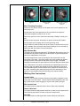
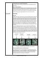
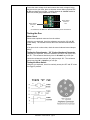
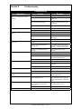
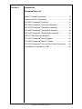
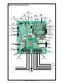
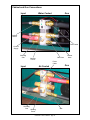
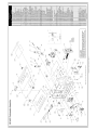
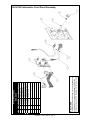
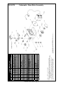
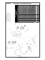
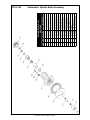
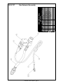
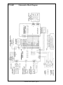
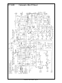
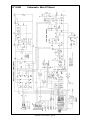
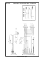
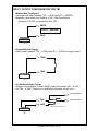
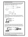
Cobramatic®
Wire Feed Cabinet
Owner’s Manual
Product:
Cobramatic®
Manual:
091-0539
Serial:
06110001
Voltage Rating: 115 VAC
Revision:
January 2010
Rev E
Model Number: 150-006
Table of Contents
Safety Guidelines
Installation................................................................................. Section A
Technical Specifications......................................................................................... 1
Machine Grounding............................................................................................... 1
Machine Location................................................................................................... 1.
Input Power Connections....................................................................................... 1
Wire Threading Procedure..................................................................................... 2
Welding Gun Connections..................................................................................... 3
Operation...................................................................................Section B
General Description............................................................................................... 4
Recommended Processes and Equipment........................................................... 4
Controls and Settings............................................................................................ 5
POSA Start Operating Procedure.......................................................................... 6
Remote Operation................................................................................................. 7
Accessories...............................................................................Section C
Optional Kits.......................................................................................................... 8
Maintenance..............................................................................Section D
Routine Maintenance............................................................................................. 8
Testing the Feeder................................................................................................. 8
Testing the Gun...................................................................................................... 9
Troubleshooting.........................................................................Section E
Troubleshooting Guide......................................................................................... 10
Diagrams/Parts List .................................................................. Section F
Main PC Boards................................................................................................... 13
Mechanical........................................................................................................... 15
Electrical.............................................................................................................. 22
Safety Warnings
Warranty
Cobramatic® Owner’s Manual
Declaration of Conformity for
European Community (CE) Products
Note
This information is provided for units with CE certification (see rating label on unit).
MK Products, Inc.
Manufacturer’s Name:
16882 Armstrong Ave.
Irvine, CA 92606
Declares that the product:
Cobramatic®
conforms to the following Directives and Standards:
Directives
Low Voltage Directive: 73/23/EEC
Electromagnetic Compatibility (EMC) Directive: 89/336/EEC
Standards
Arc Welding Equipment Part I: Welding Power Sources: IEC 60974-1
(September 1998 - Second Edition)
Arc Welding Equipment: Wirefeed Systems: IEC 974-5
(September 1997 - Draft Revision)
Degrees of Protection Provided by Enclosures (IP Code): IEC 529:1989
(November 1989 - First Edition)
Insulation Coordination For Equipment With Low-Voltage Systems:
Part I: Principles, Requirements and Tests: IEC 664-1: 1992
(October 1992 - First Edition)
Electromagnetic Compatibility, (EMC): EN 50199
(August 1995)
Torches And Guns For Arc Welding, EN 50078
Cobramatic® Owner’s Manual
SAFETY CONSIDERATIONS
ELECTRIC ARC WELDING EQUIPMENT
CAUTION : READ BEFORE ATTEMPTING INSTALLATION, OPERATION
OR MAINTENANCE OF THIS EQUIPMENT
1-1 INTRODUCTION
This equipment is intended for ultimate
application by commercial/industrial users
and for operation by persons trained and
experienced in the use and maintenance of
welding equipment. Operation should not be
undertaken without adequate training in the
use of such equipment. Training is available
from many public and private schools or similar
facilities.
Safe practices in the installation, operation
and maintenance of this equipment requires
proper training in the art, a careful study of the
information provided with the equipment, and
the use of common sense. Rules for safe use
are generally provided by suppliers of welding
power sources, compressed gas suppliers,
and electrode suppliers. Careful compliance
with these rules will promote safe use of this
equipment.
The following Safety Rules cover some of the
more generally found situations. READ THEM
CAREFULLY. In case of any doubt, obtain
qualified help before proceeding.
1-2 GENERAL PRECAUTIONS
A. Burn Prevention
ELECTRIC ARC WELDING PRODUCES
HIGH INTENSITY HEAT AND ULTRAVIOLET
RADIANT ENERGY WHICH MAY CAUSE
SERIOUS AND PERMANENT EYE DAMAGE
AND WHICH MAY DAMAGE ANY EXPOSED
SKIN AREAS.
Wear helmet with safety goggles or glasses
with side shields underneath, appropriate filter
lenses or plates (protected by clear cover
glass). This is a must for welding or cutting
(and chipping) to protect the eyes from radiant
energy and flying metal. Replace cover glass
when broken, pitted, or spattered.
Medical first aid and eye treatment. First aid
facilities and a qualified first aid person should
be available for each shift unless medical
facilities are close by for immediate treatment
of flash burns of the eyes and skin burns.
Wear protective clothing - leather (or asbestos)
gauntlet gloves, hat, and high safety-toe shoes.
Button shirt collar and pocket flaps, and wear
cuffless trousers to avoid entry of sparks and
slag.
Avoid oily or greasy clothing. A spark may
ignite them.
Ear plugs should be worn when working on
overhead or in a confined space. A hard hat should
be worn when others work overhead.
or doors, and through wall or floor openings,
out of sight of the goggled operator. Sparks
can fly many feet.
B. Toxic Fume Prevention
To prevent fires and explosion:
WARNING: The use of this product may result
in exposure to chemicals known to the State of
California to cause cancer and birth defects or
other reproductive harm.
Keep equipment clean and operable, free of
oil, grease, and (in electrical parts) of metallic
particles that can cause short circuits.
Adequate ventilation. Severe discomfort, illness
or death can result from fumes, vapors, heat, or
oxygen enrichment or depletion that welding (or
cutting) may produce. Prevent them with adequate
ventilation. NEVER ventilate with oxygen.
Lead-, cadmium-, zinc-, mercury-, beryllium-bearing
and similar materials, when welded or cut, may
produce harmful concentrations of toxic fumes.
Adequate local exhaust ventilation must be used,
or each person in the area, as well as the operator,
must wear an air-supplied respirator. For beryllium,
both must be used.
Metals coated with or containing materials that emit
toxic fumes should not be heated unless coating
is removed form the work surface, the area is well
ventilated, or the operator wears an air-supplied
respirator.
Work in a confined space only while it is being
ventilated and, if necessary, while wearing an airsupplied respirator.
Gas leaks in a confined space should be avoided.
Leaked gas in large quantities can change oxygen
concentration dangerously. Do not bring gas
cylinders into a confined space.
Leaving confined space, shut OFF gas supply at
source to prevent possible accumulation of gases
in the space if downstream valves have been
accidentally opened or left open. Check to be sure
that the space is safe before reentering it.
Vapors from chlorinated solvents can be
decomposed by the heat of the arc (or flame) to
form PHOSGENE, a highly toxic gas, and other
lung and eye irritating products. The ultraviolet
(radiant) energy of the arc can also decompose
trichloroethylene and perchloroethylene vapors
to form phosgene. DO NOT WELD or cut where
solvent vapors can be drawn into the welding or
cutting atmosphere or where the radiant energy can
penetrate to atmospheres containing even minute
amounts of trichloroethylene or perchloroethylene.
C. Fire and Explosion Prevention
Flammable hair preparations should not be
used by persons intending to weld or cut.
Causes of fire and explosion are: combustibles
reached by the arc, flame, flying sparks, hot slag,
or heated material, misuse of compressed gases
and cylinders, and short circuits.
Hot metal such as electrode stubs and work
pieces should never be handled without gloves.
BE AWARE THAT flying sparks or falling slag can
pass through cracks, along pipes, through windows
Cobramatic® Safety - page iii
If combustibles are in area, do NOT weld or
cut. Move the work if practicable, to an area
free of combustibles. Avoid paint spray rooms,
dip tanks, storage areas, ventilators. If the
work cannot be moved, move combustibles at
least 35 feet away, out of reach of sparks and
heat; or protect against ignition with suitable
and snug-fitting, fire-resistant covers or shields.
Walls touching combustibles on opposite
sides should not be welded on (or cut).
Walls, ceilings, and floor near work should be
protected by heat-resistant covers or shields.
Fire watcher must be standing by with suitable
fire extinguishing equipment during and for
some time after welding or cutting if:
1. Appreciable combustibles (including building
construction) are within 35 feet.
2. Appreciable combustibles are further than
35 feet, but can be ignited by sparks.
3. Openings (concealed or visible) in floors or
walls within 35 feet may expose combustibles
to sparks.
4. Combustibles adjacent to walls, ceilings,
roofs, or metal partitions can be ignited by
radiant or conducted heat.
Hot work permit should be obtained before
operation to ensure supervisor’s approval that
adequate precautions have been taken.
After work is done, check that area is free of
sparks, glowing embers, and flames.
An empty container that held combustibles,
or that can produce flammable or toxic vapors
when heated, must never be welded on or
cut, unless container has first been cleaned in
accordance with industry standards.
This includes: a thorough steam or caustic
cleaning (or a solvent of water washing,
depending on the combustible’s solubility),
followed by purging and inerting with nitrogen
or carbon dioxide, and using protective
equipment.
Water-filling just below working level may
substitute for inerting.
A container with unknown contents should
be cleaned (see paragraph above). Do NOT
depend on sense of smell or sight to determine
if it is safe to weld or cut.
Hollow castings or containers must be vented
before welding or cutting. They can explode.
Explosive atmospheres. NEVER weld or cut
where the air may contain flammable dust, gas,
or liquid vapors (such as gasoline).
D. Compressed Gas Equipment
The safe handling of compressed gas
equipment is detailed in numerous industry
publications. The following general rules cover
many of the most common situations.
1. Pressure Regulators
Regulator relief valve is designed to protect
only the regulator from overpressure; it is
not intended to protect any downstream
equipment. Provide such protection with one
or more relief devices.
Passageways and work areas. Keep cylinders clear
of areas where they may be stuck.
Transporting cylinders. With a crane, use a secure
support such as a platform or cradle. Do NOT lift
cylinders off the ground by their valves or caps, or
by chains, slings, or magnets.
Do NOT expose cylinders to excessive heat,
sparks, slag, and flame, etc. that may cause
rupture. Do not allow contents to exceed 55
degrees C (130 degrees F.) Cool with water spray
where such exposure exists.
Protect cylinders, particularly valves from bumps,
falls, falling objects, and weather. Replace caps
securely when moving cylinders.
Stuck valve. Do NOT use a hammer or wrench to
open a cylinder valve that cannot be opened by
hand. Notify your supplier.
Never connect a regulator to a cylinder
containing gas other than that for which the
regulator was designed.
Mixing gases. NEVER try to mix any gases in a
cylinder.
Remove faulty regulator from service
immediately for repair (first close cylinder
valve). The following symptoms indicate a
faulty regulator:
Cylinder fittings should never be modified or
exchanged.
Leaks - if gas leaks externally.
Excessive Creep - if delivery pressure
continues to rise with downstream valve
closed.
Faulty Gauge - if gauge pointer does not move
off stop pin when pressurized, nor returns to
stop pin after pressure release.
Repair. Do NOT attempt repair. Send faulty
regulators for repair to manufacturer’s
designated repair center, where special
techniques and tools are used by trained
personnel.
2. Cylinders
Cylinders must be handled carefully to prevent
leaks and damage to their walls, valves, or
safety devices:
Avoid electrical circuit contact with cylinders
including third rails, electrical wires, or welding
circuits. They can produced short circuit arcs
that may lead to a serious accident. (See 1-3C)
ICC or DOT marking must be on each cylinder.
It is an assurance of safety when the cylinder is
properly handled.
Identifying gas content. Use only cylinders with
name of gas marked on them; do not rely on
color to identify gas content. Notify supplier if
unmarked. NEVER DEFACE or alter name,
number, or other markings on a cylinder. It is
illegal and hazardous.
Empties: Keep valves closed, replace caps
securely; mark MT; keep them separate from
FULLS, and return promptly.
Prohibited use. Never use a cylinder or its
contents for other than its intended use,
NEVER as a support or roller.
Locate or secure cylinders so they cannot be
knocked over.
NEVER refill any cylinder.
3. Hose
Prohibited use. Never use hose other than that
designed for the specified gas. A general hose
identification rule is: red for fuel gas, green for
oxygen, and black for inert gases.
Use ferrules or clamps designed for the hose (not
ordinary wire or other substitute) as a binding to
connect hoses to fittings.
No copper tubing splices. Use only standard brass
fittings to splice hose.
Avoid long runs to prevent kinks and abuse.
Suspend hose off ground to keep it from being run
over, stepped on, or otherwise damaged.
Coil excess hose to prevent kinks and tangles.
Protect hose from damage by sharp edges, and by
sparks, slag, and open flame.
Examine hose regularly for leaks, wear, and loose
connections. Immerse pressured hose in water;
bubbles indicate leaks
Repair leaky or worn hose by cutting area out and
splicing. Do NOT use tape.
4. Proper Connections
Clean cylinder valve outlet of impurities that may
clog orifices and damage seats before connecting
regulator. Except for hydrogen, crack valve
momentarily, pointing outlet away from people and
sources of ignition. Wipe with a clean, lintless
cloth.
Match regulator to cylinder. Before connecting,
check that the regulator label and cylinder marking
agree, and that the regulator inlet and cylinder
outlet match. NEVER Connect a regulator
designed for a particular gas or gases to a cylinder
containing any other gas.
Tighten connections. When assembling
threaded connections, clean and smooth seats
where necessary. Tighten. If connection leaks,
disassemble, clean, and retighten, using properly
fitting wrench.
Cobramatic® Safety - page iv
Adapters. Use a CGA adapter (available from
your supplier) between cylinder and regulator,
if one is required. Use two wrenches to tighten
adapter marked RIGHT and LEFT HAND
threads.
Regulator outlet (or hose) connections may be
identified by right hand threads for oxygen and
left hand threads (with grooved hex on nut or
shank) for fuel gas.
5. Pressurizing Steps:
Drain regulator of residual gas through suitable
vent before opening cylinder (or manifold
valve) by turning adjusting screw in (clockwise).
Draining prevents excessive compression
heat at high pressure seat by allowing seat to
open on pressurization. Leave adjusting screw
engaged slightly on single-stage regulators.
Stand to side of regulator while opening
cylinder valve.
Open cylinder valve slowly so that regulator
pressure increases slowly. When gauge
is pressurized (gauge reaches regulator
maximum) leave cylinder valve in following
position: for oxygen and inert gases, open
fully to seal stem against possible leak; for fuel
gas, open to less than one turn to permit quick
emergency shut-off.
Use pressure charts (available from your
supplier) for safe and efficient recommended
pressure settings on regulators.
Check for leaks on first pressurization and
regularly thereafter. Brush with soap solution.
Bubbles indicate leaks. Clean off soapy water
after test; dried soap is combustible.
E. User Responsibilities
Follow all Safety Rules.
Remove leaky or defective equipment from
service immediately for repair. Read and follow
user manual instructions.
F. Leaving Equipment Unattended
Close gas supply at source and drain gas.
G. Rope Staging-Support
Rope staging-support should not be used for
welding or cutting operation; rope may burn.
1-3 ARC WELDING
Comply with precautions in 1-1, 1-2, and this
section. Arc Welding, properly done, is a
safe process, but a careless operator invites
trouble. The equipment carries high currents
at significant voltages. The arc is very bright
and hot. Sparks fly, fumes rise, ultraviolet and
infrared energy radiates, weldments are hot,
and compressed gases may be used. The
wise operator avoids unnecessary risks and
protects himself and others from accidents.
A. Burn Protection
Comply with precautions in 1-2.
The welding arc is intense and visibly bright.
Its radiation can damage eyes, penetrate
lightweight clothing, reflect from light-colored
surfaces, and burn the skin and eyes. Skin
burns resemble acute sunburn; those from
gas-shielded arcs are more severe and painful.
DON’T GET BURNED; COMPLY WITH
PRECAUTIONS.
1. Protective Clothing
Wear long-sleeve clothing in addition to gloves,
hat, and shoes. As necessary, use additional
protective clothing such as leather jacket or
sleeves, flameproof apron, and fire-resistant
leggings. Avoid outer garments of untreated
cotton.
Bare skin protection. Wear dark, substantial
clothing. Button collar to protect chest and
neck, and button pockets to prevent entry of
sparks.
2. Eye and Head Protection
Protect eyes from exposure to arc. Eyes may
be damaged by radiant energy when exposed
to the electric arc, even when not looking in the
direction of the arc. Never look at an electric
arc without protection.
Welding helmet or shield containing a filter
plate shade no. 12 or denser must be used
when welding. Place over face before striking
arc.
Protect filter plate with a clear cover plate.
Cracked or broken helmet or shield should
NOT be worn; radiation can be passed through
to cause burns.
Cracked, broken, or loose filter plates must be
replaced IMMEDIATELY. Replace clear cover
plate when broken, pitted, or spattered.
Flash goggles with side shields MUST be worn
under the helmet to give some protection to the
eyes should the helmet not be lowered over the
face before an arc is struck. Looking at an arc
momentarily with unprotected eyes (particularly
a high intensity gas-shielded arc) can cause a
retinal burn that may leave a permanent dark
area in the field of vision.
3. Protection of Nearby Personnel
Enclose the welding area. For production
welding, a separate room or enclosed bay is
best. In open areas, surround the operation
with low-reflective, noncombustible screens
or panels. Allow for free air circulation,
particularly at floor level.
Viewing the weld. Provide face shields for all
persons who will be looking directly at the weld.
Others working in area. See that all persons
are wearing flash goggles.
Before starting to weld, make sure that screen
flaps or bay doors are closed.
B. Toxic Fume Prevention
Comply with precautions in 1-2B.
Generator engine exhaust must be vented to
the outside air. Carbon monoxide can kill.
C. Fire and Explosion Prevention
Comply with precautions in 1-2C.
Equipment’s rated capacity. Do not overload
arc welding equipment. It may overheat cables
and cause a fire.
Loose cable connections may overheat or flash
and cause afire.
Never strike an arc on a cylinder or other pressure
vessel. It creates a brittle area that can cause a
violent rupture or lead to such a rupture later under
rough handling.
D. Compressed Gas Equipment
Comply with precautions in 1-2D.
E. Shock Prevention
Exposed electrically hot conductors or other bare
metal in the welding circuit, or in ungrounded,
electrically-HOT
equipment can fatally shock a person whose body
becomes a conductor. DO NOT STAND, SIT, LIE,
LEAN ON, OR TOUCH a wet surface when welding
without suitable protection.
To protect against shock:
Keep body and clothing dry. Never work in damp
area without adequate insulation against electrical
shock. Stay on a dry duckboard, or rubber mat
when dampness or sweat cannot be avoided.
Sweat, sea water, or moisture between body and
an electrically HOT part - or grounded metal reduces the body surface electrical resistance,
enabling dangerous and possibly lethal currents to
flow through the body.
1. Grounding the Equipment
When installing, connect the frames of each unit
such as welding power source, control, work
table, and water circulator to the building ground.
Conductors must be adequate to carry ground
currents safely. Equipment made electrically HOT
by stray currents may shock, possibly fatally. Do
NOT GROUND to electrical conduit, or to a pipe
carrying ANY gas or a flammable liquid such as oil
or fuel.
Three-phase connection. Check phase requirement
of equipment before installing. If only threephase power is available, connect single-phase
equipment to only two wires of the three-phase
line. Do NOT connect the equipment ground lead
to the third (live) wire, or the equipment will become
electrically HOT - a dangerous condition that can
shock, possibly fatally.
Before welding, check ground for continuity. Be
sure conductors are touching bare metal of
equipment frames at connections.
If a line cord with a ground lead is provided with
the equipment for connection to a switch box,
connect the ground lead to the grounded switch
box. If a three-prong plug is added for connection
to a grounded mating receptacle, the ground lead
must be connected to the ground prong only. If the
line cord comes with a three-prong plug, connect
to a grounded mating receptacle. Never remove
the ground prong from a plug, or use a plug with a
broken ground prong.
2. Connectors
Fully insulated lock-type connectors should be
used to join welding cable lengths.
3. Cables
Frequently inspect cables for wear, cracks, and
damage. IMMEDIATELY REPLACE those with
excessively worn or damaged insulation to avoid
possibly lethal shock from bared cable. Cables
Cobramatic® Safety - page A
with damaged areas may be taped to give
resistance equivalent to original cable.
Keep cable dry, free of oil and grease, and
protected from hot metal and sparks.
4. Terminals and Other Exposed Parts
Terminals and other exposed parts of electrical
units should have insulating covers secured
before operation.
5. Electrode Wire
Electrode wire becomes electrically HOT when
the power switch of gas metal-arc welding
equipment is ON and welding gun trigger is
pressed. Keep hands and body clear of wire
and other HOT parts.
6. Safety Devices
Safety devices such as interlocks and circuit
breakers should not be disconnected or
shunted out.
Before installation, inspection, or service of
equipment, shut OFF all power, and remove
line fuses (or lock or red-tag switches) to
prevent accidental turning ON of power.
Disconnect all cables from welding power
source, and pull all 115 volts line-cord plugs.
Do not open power circuit or change polarity
while welding. If, in an emergency, it must be
disconnected, guard against shock burns or
flash from switch arcing.
Leaving equipment unattended. Always shut
OFF, and disconnect all power to equipment.
Power disconnect switch must be available
near the welding power source.
Thank You
For selecting a quality product. We want you to take
pride in operating this product...as much pride as we
have in bringing the product to you!
Please Examine Carton and Equipment For Damage Immediately
When this equipment is shipped, title passes to the purchaser upon receipt by the
carrier. Consequently, claims for material damaged in shipment must be made by the
purchaser against the transportation company at the time the shipment is received.
Please record your equipment identification information below for future reference. This
information can be found on your machine nameplate.
Model Name & Number
_____________________
Code & Serial Number
_____________________
Date of Purchase
_____________________
Whenever you request replacements parts for, or information on this equipment always
supply the information you have recorded above.
Read this Owner’s Manual completely before attempting to use this equipment. Save this manual
and keep it handy for quick reference. Pay particular attention to the safety instructions we
have provided for your protection.
Cobramatic® Owner’s Manual
Section A
Installation
Technical Specifications
Wire Diameter Capacity . ..................................... .030 - 1/16”
Wire Spool Capacity ............................................ 12” Standard
(Insulated or Non-Insulated)
Power Input .......................................................... 115 VAC 50/60 Hz,
. ............................................................................ 150 Watts Peak (1.3 amps)
Weight . ................................................................. 41 pounds
Shipping Weight .................................................. 46 pounds
Support Equipment Required
C.V. or C.C. Power Source of Sufficient Capacity for Your Needs.
Regulated Gas Supply and Hoses.
Properly Sized Power Leads from Power Source to Wire Feeder and Ground.
Coolant Recommendations for Liquid Cooled Guns
Use Cobra Coolant (Aluminum Protection), P/N 931-0060. Cobra Coolant
does not contain reactive sulphur or chlorine and does not react with copper,
brass or aluminum.
The coolant flow rate should be a minimum of 15 GPH (1 qt/min) between 35
and 45psi. Contact the re-circulator manufacturer for specifications on pressure.
Machine Grounding
The Cobramatic® is grounded with the power source through the input power
cable. The power source grounding terminal must be properly connected to
electrical ground per the power source operating manual.
Mounting Location
The cabinet should be placed in a location where it can be protected from
damage. Lead lengths and accessibility must also be considered when
installing the cabinet.
Input Connections
(See Cabinet and Gun Hook-Up in the Appendix)
115 VAC
Your Wire Feeder comes factory ready with a standard 3-prong plug ready to
connect into any standard 115 VAC, 15 A receptacle. Several optional, prewired harnesses are available for different power supplies and may be factory installed for a nominal installation fee. See part numbers and description
of each in the OPTIONAL KITS section of this manual.
The 115 VAC input power is connected to the PC Board on terminal strip J5
#1 (neutral-white) and J5 #2 (hot-black) and Ground (green) to the Cabinet
chassis. See diagram in the appendix.
Shielding Gas
In accordance with the required support equipment, the customer must provide a cylinder of shielding gas, a pressure regulator, a flow control valve,
and a hose from the flow control valve to the left bottom-most fitting on the
power block.
The end of the hose must have a male connector to fit the female 5/8-18
brass fitting. Use a 11/16” wrench to tighten.
Cobramatic® Owner’s Manual - page 1
Coolant Supply and Return for Liquid Cooled Guns
Using a recirculator with properly mixed coolant, as previously described,
connect the coolant RETURN hose to the left middle fitting on the power
block. Connect the coolant SUPPLY hose to the left top-most fitting on the
power block (See Cabinet and Gun Connections page 16).
The coolant hoses must have a male 5/8-18 left-hand thread to connect to
the power block fittings. Use an 11/16” wrench to tighten.
Welding Power
The electrode cable coming from the welding power supply should be affixed
with a 1/2” copper ring lug. Use a 9/16” wrench to tighten.
Cable from power supply MUST connect to bottom bolt of power block.
Reference Input Connections figure in the Appendix.
Wire Threading Procedure
Wire Spool Installation
Release latches, and open right side door of cabinet (Reference Cobramatic®
Assembly drawing).
Remove spool retainer nut from spindle hub (Reference Cobramatic® Spindle
Brake Assembly drawing).
Raise wire retainer bar to latched position (Reference Cobramatic® Assembly
drawing).
Install wire spool onto spindle so that wire feeds from bottom of spool
towards slave motor. Make sure that the hole in the wire spool aligns with
pin on spindle. The white dot on the end of the spindle will aid in this alignment.
Replace the spool retainer nut.
Lower the wire retainer bar onto the spool.
Wire Spool Drag Setting
NOTE:
Standard factory setting of the Spindle Tension Knob is set for All
Other Wires.
There are two visible position settings for this Knob, IN - All Other Wires (Fig.
1) and, OUT - .030/.035 Al Only (Fig. 2). The Spindle Tension Knob must be
set to match the Wire Size Selector Switch on the Cobramatic® front panel.
To change this setting, it is easily done without the spool of wire on the spindle. Remove the wire spool retainer nut and re-install it reversed back onto
the Spindle Tension Knob (Fig. 3). In the “Tool Mode”, the square shaped
end of the retainer fits onto the Knob. Grab the retainer nut and turn in the
COUNTER-CLOCKWISE direction until it stops. The Knob is now set to the
OUT position (.030/.035 AL Only).
To reset the Knob back to the factory setting of All Other Wires, use the
retainer nut as described above, and turn in the CLOCKWISE direction until
it stops. The Spindle Knob is now set to the IN position. Turning the retainer
nut and Spindle Knob in this direction may require more effort, since turning
CLOCKWISE is working against a spring.
Load wire spool onto spindle according to the previous instructions.
Replace the spool retainer nut.
Lower the wire retainer bar onto the spool.
Cobramatic® Owner’s Manual - page 2
IN - All other wires
Figure 1
OUT - .030/.035
Aluminum ONLY
Figure 2
Wire Spool Retainer In "Tool
Mode"; used to change
spindle drag.
Figure 3
Wire Threading Procedure
Place wire size selector switch on front panel to the correct position for the
wire being used.
Loosen end of wire from spool and cut off any kinked or bent portions.
Unreel and straighten out first 6” to 8” of wire.
Raise wire type lever on the slave motor assembly of feeder to center position.
Route wire into inlet guide, along drive roll groove, and into wire conduit.
Flip wire type lever to display name of wire type being used.
Proper tension is achieved when wire does not slip if a small amount of pressure is added to the wire between thumb and forefinger as wire exits the tip.
Adjust gun idler arm tension screw as necessary.
Wire Retainer Bar
The design of the patented Cobramatic® Wire Retainer Bar performs two very
important and very basic functions of the wire feeder: a) spool drag tension,
and b) wire maintenance on the spool.
The spool drag tension is set by lowering the wire retainer bar onto the
wire inside of the spool. The spring tension of the wire retainer bar applies
enough pressure on the spool so that when the gun trigger is released,
engaging the brake pall, the spool does not overrun kicking wire off the spool.
Wire maintenance on the spool is performed by the applied pressure of the
surface of the wire retainer bar spread across the coiled wire on the spool.
The replaceable pad of the wire retainer bar is designed to hold the wire on
the spool, maintaining the smooth layering of the wire and keeping it from
jumping off, and possibly electrically shorting to the cabinet chassis.
Welding Gun Connections
Control Cable
The 7-Pin “W” Clocked connector screws onto the mating receptacle on the
front panel of the wire feeder. This provides all electrical signals (motor voltage, potentiometer control & trigger) to and from the feeder to the gun.
Wire Conduit Inlet
Front panel access to attach conduit to front of slave motor assembly.
Power Cable Inlet
Front panel access to attach power cable (air or water) to top of power block.
Guns with ring lugs, MUST connect to top bolt of power block.
Gas Inlet
Front panel access to attach gas hose to bottom fitting of power block.
Cobramatic® Owner’s Manual - page 3
Coolant Inlet (For Liquid Cooled Guns)
Front panel access to connect the coolant hose to the middle fitting on the
power block.
Work Cable (Ground)
Connect a work lead of sufficient size and length between the proper output
stud on the power source and the work. Be sure the connection to the work
ground makes tight metal to metal electrical contact. Improper work lead
connections can result in poor arc initiation, and unsatisfactory weld results.
Consult welding power supply manufacturer for proper work lead size.
Section B
Operation
General
The AC slave motor in the feeder runs at a fast, constant speed, but has very
low torque. It is always trying to feed more wire than the gun motor wants,
and when the gun motor gets all the wire it wants, the slave motor automatically slows, preventing a bird’s nest. Because of the low torque produced
by the slave motor, a combination drag and electric brake system is used to
prevent wire overrun rather than relying on spindle tension alone. The spool
drag tension is produced by the patented Wire Retainer Bar mechanism to
keep the wire slightly taut. The 24 VDC gun “pull” motor is controlled by a
solid state speed control in the cabinet and through a potentiometer located
in the gun.
The normal operating sequence of the wire feeder can be viewed on the
board itself via sequence LED’s. When the system is triggered, the green
Trigger LED (L3) and the yellow Gas Solenoid LED (L1) illuminate simultaneously. The red Contactor/Wire Feed LED (L2) illuminates after the prepurge
time. The blue Arc On LED (LED) illuminates as the arc is established. When
the trigger is released the normal LED operating sequence is blue, green and
red (L4, L3, & L2) turn off simultaneously followed by the yellow (L1) after the
postpurge time has elasped (Figure 4).
Yellow LED
when solenoid
opens.
L1
Red LED when
wire feeds/
contactor closes.
L2
Green LED
when triggered.
L3
Blue LED
when arc established
L4
Figure 4 - L1, L2 & L3
For reference, see Main P.C. Board Connections picture in Section F
Recommended Processes and Equipment
The Cobramatic® feeder is recommended for use with GMAW and FCAW
welding applications. It is recommended for use with constant voltage power
sources but will also work with CC machines. The Cobramatic® feeder is
capable of feeding wires (diameter capacity) ranging from .030” through
.045” solid/cored and .030” through 1/16” aluminum.
Cobramatic® Owner’s Manual - page 4
Controls and Settings
On/Off Switch
Placing the switch in the “ON” position energizes the feeder circuitry and the
power indicator light.
Wire Size Selector Switch
The wire size selector switch changes the torque of the slave motor for the
wire you are using. When in the .030-.035 aluminum only position, the slave
motor produces approximately 1 1/2 lbs./inch of torque and approximately 4
1/2 lbs./inch when in the all other wires position.
NOTE:
Operating the cabinet with the switch in the wrong
position will cause wire feed difficulties.
PosaStart Switch & Run In Speed Setting
The Posa Start Run-in Speed Control, located on the front panel, provides
wire speed adjustment for slow wire run-in. This setting tracks as a percentage of the welding wire speed setting. Once the arc has been established,
the wire feed speed automatically changes from the slow run-in speed to the
welding wire speed set on the gun potentiometer.
PosaStart operation and configuration is explained later in this section.
Trigger Normal/Trigger Latched
This switch configures the electronic Trigger Latching mechanism. In the
Trigger “Normal” mode, pull and hold the trigger to start welding functions
- release trigger to stop welding functions. In the Trigger “Latched” mode pull
and release trigger, to start welding functions- pull trigger again and release,
to stop welding functions.
The Prepurge/Postpurge functions are pre-configured to provide a preset
amount of pre & postpurge gas time; 0.25 and 2.0 second respectively. The
default factory position of this jumper is horizontal (top right) across pins.
Changing the position of the JP3 jumper changes the configuration of the pre
& postpurge sequences. Refer to Figure 5 for the desired pre and postpurge
sequence. Once the desired sequence is selected, relocate on JP3 jumper
from its horizontal default pattern (top right) to its new vertical sequence positurn.
Figure 5
Pre-Purge Settings & Adjustments (JP2)
The Pre-Purge Jumper/Pot Configuration at JP2 has 3 available settings:
0.25 sec. fixed, variable from 0-1 sec. or variable from 0-5 seconds.
By default, the twin two-pin jumpers, across rows 1 & 3, are configured for
0.25 sec. Just to the left of the jumpers is a ¾-turn potentiometer (pot) which
is used with both variable settings. For the 0-1 sec. range, move the jumpers
Cobramatic® Owner’s Manual - page 5
across rows 3 & 5. For the 0-5 second range, move the jumpers across rows
5 & 7 (Figure 6a).
Timing adjustment for the variable settings are as follows: Move the jumpers
to either variable setting location. Turn potentiometer screw (Small flat or
cross-head) half way. Pull gun trigger and count time between red contactor
wire feed LED (L2) and yellow Gas Solenoid LED (L1). Adjust pot screw as
necessary.
Rows 1 & 3: 0.25 sec. fixed
Rows 3 & 5: 0-1 sec.
Rows 5 & 7: 0-5 sec.
Figure 6a
Post-Purge Settings & Adjustments (JP1)
The Post-Purge Jumper/Pot Configuration at JP1 has 2 available settings: 2
sec. fixed and variable from 0-5 seconds.
By default, the two-pin jumper across the top-and-middle pins, is configured
for 2 sec. Just to the left of the jumper is a ¾-turn pot which is used with the
variable setting. For the 0-5 second range, move the jumper from the topand-middle to the middle-and-bottom pins (Figure 6b).
Timing adjustment for the variable settings are as follows: Move the jumpers
to variable setting location. Turn potentiometer screw (Small flat or crosshead) half way. Upon release of gun trigger, count time between yellow Gas
Solenoid LED (L1) and green Trigger LED (L3). Adjust as necessary.
Middle/Bottom: 0-5 sec.
Figure 6b
Top/Middle: 2 sec fixed
Posa Start Operating Procedure
CAUTION:
Do not operate this wire feeder on a power source having a high-frequency (HF) starting circuit until the high frequency feature has been
turned off or disabled. Failure to disable the HF will result in damage
to the PosaStart circuitry of the main board.
General
The Posa Start Run-in Speed Control, located on the front panel, provides
adjustment for slow wire run-in. Once the arc has been established, the wire
feed speed is automatically changed from the slow run-in speed to the welding speed set on the gun potentiometer.
Cobramatic® Owner’s Manual - page 6
The Posa Start feature allows the Cobramatic® feeder and gun to be used
in conjunction with constant current DC welding power sources of open circuit voltage in excess of 55 volts - also, any constant voltage welding power
source capable of a minimum of 50 amps.
Once the PosaStart circuit has transferred from slow run-in to weld speed,
the blue LED (L4) illuminates (Figure 7).
Blue LED
when PosaStart engages.
L4
Figure 7
CV/CC Posa Start Operations
Note:
CV Posa Start does not need welding voltage sensing lead.
The default factory setting is CV mode. Attach Cobramatic® cabinet to CV
power source according to the installation instructions.
Turn the Cobramatic® cabinet to the “ON” position and the Posa Start to the
“OFF” position. Adjust power source to desired voltage for your weld condition. Depress gun trigger and adjust wire feed speed at gun to match voltage
setting.
Turn the Posa Start switch to the “ON” position. Depress gun trigger and,
using Run-in Speed Control, adjust wire feed rate to approximately 50% of
welding wire speed set at gun.
Initiate an arc, and adjust wire feed speed at gun until correct condition is
achieved. At the moment when welding wire speed transition occurs, L4 will
illuminate.
POSA START WIRE SPEED NOTE:
Because the Posa Start Run-in Speed always remains a percentage
of the actual welding wire feed rate, the Posa Start run-in speed
will always slow down or speed up proportional to any
adjustment you now make at the gun. Therefore, if you slow down
the welding wire feed speed, you will have to increase
the Run-in Speed setting.
Remote Operation: Input/Ouput
The terminal strip TB1(reference Appendix pages) allows for external input
signals for remote operation of the feeder as well as output signals for voltage and wire speed measurements, for a wide variety of automatic and semiautomatic applications. By making connections across specific points of
TB1, such functions as the trigger and motor speed control can be controlled
using an external source, such as a controller interface or a PLC (programmable logic controller).
Figure 8
Cobramatic® Owner’s Manual - page 7
Section C
Optional Kits
The following is a list of Optional Power Supply Interface Cable Kits available
for the Cobramatic® Wire Feeder.
8ft Interface Cable for Miller 14-Pin, 115VAC.................................005-0316
25ft Interface Cable for Miller 14-Pin, 115VAC...............................005-0658
When properly connected, these interface cables will supply all the necessary signals and power needed, from most Miller welding power supplies: a
Closing Contact signal and 115VAC input power.
8ft Interface Cable for Lincoln 14-Pin, 115VAC.............................. 005-0608
25ft Interface Cable for Lincoln 14-Pin, 115VAC............................ 005-0659
When properly connected, these interface cables will supply all the necessary signals and power needed, from most Lincoln Electric welding power
supplies: a Closing Contact signal and 115VAC input power.
8ft Interface Cable for Thermal Arc 19-Pin, 115VAC...................... 005-0630
When properly connected, these interface cables will supply all the necessary signals and power needed, from most Thermal Arc welding power supplies: a Closing Contact signal and 115VAC input power.
8ft Interface Cable for ESAB 19-Pin, 115VAC................................. 005-0705
When properly connected, these interface cables will supply all the necessary signals and power needed, from most ESAB welding power supplies: a
Closing Contact signal and 115VAC input power.
Section D
Maintenance
Routine Maintenance
Your Cobramatic® system is designed to provide years of reliable service.
Normal wear and component mortality may require occasional service.
The number of units in operation and the importance of minimal “down time”
will determine to what extent spare parts should be stocked on hand.
If repairs do become necessary, any part can easily be replaced by qualified
shop maintenance personnel.
Maintenance of the gun will normally consist of a general cleaning of the wire
guide system, including tubes, drive rolls, and conduits at regular intervals.
Remove spatter build-up from inside of nozzles with a hardwood stick.
The only parts on the Cobramatic® system that are subject to normal wear
are the conduit, contact tips, gas cups, front body liners, wire guides, drive
and idler rolls (parts that contact the welding wire). A supply of these parts
should be maintained.
Testing the Feeder
Testing the Input Power Circuits
The AC circuits are protected by fuses F1 and F2 (see page 15 for location).
If these fail, especially when powering up the cabinet, remove the connectors
for the components that draw on this power, J6 (Brake Solenoid), J7 (Slave
Motor) and J5-3 & 4 (AC Contactor - if used) from the P.C. Board. Replace
fuses and retrigger system. If fuses do not fail, isolate the problem by plugging in J4, J7, and J5-3,4 one at a time until the fuses fail.
Testing the Speed Control
NOTE:
The gun should be tested prior to testing circuitry on the main board.
Gun amphenol must be connected to the Cobramatic® cabinet to perform the following tests.
Cobramatic® Owner’s Manual - page 8
To test the motor voltage circuit and measure how much voltage is being
delivered to the gun motor, place a voltmeter across diode test points TP1
& TP2 and depress gun trigger. A reading between 0 - 30 VDC should be
observed, as the gun potentiometer is varied.
Motor Voltage
Test Point
TP1
Motor Voltage
Test Point
TP2
Figure 9
For reference, see Main P.C. Board Connections picture in Section F
Testing the Gun
Motor Check
Remove the amphenol connector from the cabinet.
Using the gun amphenol, check the resistance across pins “A” and “B”
(motor leads). The resistance across the motor should be between 5-10
ohms.
If an open circuit or short exists, check the motor leads and motor independently.
Testing the Potentiometer - “W” Clocked Amphenol Connector
Using the gun amphenol, check the resistance across pin “D” (wiper) and
pin “C”. The resistance should vary from 0 - 5K ohms as you turn pot..
Check the resistance across pin “D” (wiper) and pin “G”. The resistance
should vary from 5K - 0 ohms as you turn pot.
Testing the Micro Switch
Using the gun amphenol, check for continuity across pins “E” and “F” when
the trigger is pressed.
Cobramatic® Owner’s Manual - page 9
Section E
Troubleshooting
Symptom
No wire feed at gun, feeder not operating, i.e., no slave motor or brake
solenoid.
Brake solenoid inoperative.
No wire feed at gun, feeder operating
properly.
Wire feeds, but welding wire is not
energized.
Wire feeds erratically.
Wire feeds one speed only.
Troubleshooting
Cause
Remedy
F1 & F2 fuse(s) in feeder failed.
Check AC circuit. Replace fuse(s).
F3 (4 amp) fuse in feeder failed.
Check motor leads for shorts then
replace fuse.
Micro-switch defective/not being activated. Broken electrical cable.
Replace switch. Check switch for
operation. Check micro switch wires
for continuity.
Loose J2, J3, P.C. board connector.
Check J2, J3 connectors.
Solenoid defective.
Replace solenoid.
Loose connector at J6.
Check J6 connector.
Bad potentiometer.
Check potentiometer with meter.
Bad gun motor.
Check/Replace motor.
Broken electrical cable.
Check motor and potentiometer wires
for continuity.
Bad speed control/PCB.
Check/Replace P.C. board.
Loose or no power supply cable connections.
Check all power connections.
Contactor control cable loose or in
wrong position.
Check power supply owner’s manual
for location and type of contactor signal
required, i.e. closing contacts or AC.
Welding power source not working
correctly.
Check power supply for proper
operation.
Dirty or worn conduit.
Blow out or replace conduit.
Incorrect pressure on drive rolls.
Adjust pressure at gun (Gold or Prince)
Idler roll stuck in gun.
Check for lock washer under idler roll,
or replace if damaged or worn.
Wrong size contact tip.
See contact tip table.
Bad potentiometer.
Check with meter.
Broken electrical cable in lead assy.
Check potentiometer wires for continuity or shorts.
Bad speed control.
Check/Replace P.C. boards.
Wire walks out of drive rolls.
Idler roll upside-down.
Place groove in idler roll toward the
top.
Rear wire guide missing.
Replace wire guide.
Trigger inoperable or not operating
correctly.
Trigger mode configuration.
Check front panel Trigger Normal/
Latched toggle switch.
Purge not operating correctly.
Jumper incorrectly configured. Gas
solenoid malfunctioning.
Check jumper location per Jumper
Table in Appendix. Check cable connections to gas solenoid Check valve
in gun.
No PosaStart Wire Speed Transition
Welding power cable and/or gun power
cable connected to wrong bolt on
power block.
Welding power cable to bottom bolt.
Gun power cable to top bolt.
Welding current not being sensed.
Check current sensor in power block.
Wires not connected at TB1
Reseat all wire connections at TB1.
Remote Functions Not Working
Cobramatic® Owner’s Manual - page 10
Section F
Appendices
Diagrams/Parts List
Main P.C. Board Connections.................................................... 13
Cabinet and Gun Connections.................................................. 14
001-4021 Cobramatic® Assembly.............................................. 15
003-2235 Cobramatic® Front Panel Assembly.......................... 17
003-2078 Cobramatic® Slave Motor Assembly.......................... 18
003-2063 Cobramatic® Power Block Assembly......................... 19
003-2146 Cobramatic® Spindle Brake Assembly....................... 20
003-2137 Gas Solenoid Assembly............................................ 21
071-0401 Cobramatic® Block Diagram...................................... 23
071-0400 Cobramatic® Main P.C. Board................................... 22
071-0370 Cobramatic® Gun and Front Panel Connections....... 25
Input/Output Configuration for TB1............................................ 26
Cobramatic® Owner’s Manual - page 11
This page intentionally blank
Cobramatic® Owner’s Manual - page 12
Main P.C. Board Connections
JP1
Adj. Gas Purge Jumper
P2
Post-Purge Trim Pot
P1
Pre-Purge Trim Pot
JP2
Adj. Gas Purge Jumper
L4
JP6
Torch Select
Posa Start “on”
(blue)
TB1
Remote
Input/Output
P3
Motor Gain
L3
Trigger “on”
(green)
J11
Front Panel
JP3
Gas Purge Jumper
TP2
Test Point - MTR VDC
J2
TP1
Gas Solenoid
Test Point - GROUND
L1
TP3
Gas “on” (yellow)
Motor Demand
L2
J1
Contactor Signal
“on” (red)
Trigger Normal/Latch
J4
Front Panel
F2
Line Fuse
J7
J10
Slave Motor
Transformer
F1
Line Fuse
J8
Current Sensor
J9
Brake Solenoid
F3
Motor Fuse
J5
J6
Terminal Strip
Terminal Strip
Opt. Contactor - 115 VAC Out - Hot - Black
Opt. Contactor - 115 VAC Out - Neutral - White
Closing Contacts Out
Input Power - 115 VAC - Hot - Black
Closing Contacts Out
Input Power - 115 VAC Neutral - White
Chassis
Ground
(Green)
Cobramatic® Owner’s Manual - page 13
Cabinet and Gun Connections
Input
Gun
Water Cooled
Coolant
Return
Power Cable
Coolant
Supply
Shielding
Gas
Welding
Power
Power
Cable
Welding
Power
Cobramatic® Owner’s Manual - page 14
Coolant
Hose
Gun
Air Cooled
Input
Shielding
Gas
Gas Hose
Gas
Cobramatic® Owner’s Manual - page 15
Cobramatic® Owner’s Manual - page 16
Cobramatic® Owner’s Manual - page 16
This page intentionally blank
436-0144
003-1642
1
1
1
2
1
1
1
1
3
4
5
6
7
8
9
10
Cobramatic® Owner’s Manual - page 17
Assy swx gas/trigger
Assy con 7p “w” cb
SS pnl fr Cobramatic
Knob 1.0 blk
Nut hex lock 4-40
Nut 3/8 - 32 st
Grommet panel mount
Assy pcb fr pnl cb 1 110V
Cable power assy
Assy cbl rbn 26c
Description
DISCLAIMER
Individual components shown in the exploded parts
drawing may not necessarily appear like the true
components used. This drawing is for reference only.
003-2138
401-0012
345-0004
341-0050
301-0023
003-2024
003-1631
1
2
003-1332
1
1
No. Qty. Part No.
Front Panel Assy
003-2235
003-2235 Cobramatic® Front Panel Assembly
No. Qty.
1
1
2
1
3
1
4
4
5
1
6
1
7
1
8
1
9
1
10
1
11
1
12
1
13
1
14
1
15
1
16
1
17
1
18
1
19
1
20
1
21
1
Description
Assy knob conduit
Assy torque motor 115V
Scr shc 8-32 X 3/8 stl
Scr shc 8-32 X 1-1/8 stl
Scr Shldr 1/4 X 1/4 X 10-24
Nut Lock 5/16-18
Spring comp
Spring comp
Bolt swing mod
Plate locate slave motor
Housing slave motor mold
Handle mold slave motor
Arm idler mold slave motor
Cap bearing mold
Sleeve spring
Bearing 1.125 X .50 X .31
Bearing, .875 X .38 X .28
Bearing idler roll
Shaft gear
Drive roll
Guide wire inlet
Slave Motor Assy
Part No.
003-0176
003-2069
328-0024
328-0259
330-0258
345-0018
419-0085
419-0211
431-1576
435-1582
437-0230
437-0231
437-0232
437-0245
437-0254
501-0118
501-0156
501-0207
507-0130
511-0206
753-0210
003-2078
Cobramatic® Slave Motor Assembly
Cobramatic® Owner’s Manual - page 18
A
A
A
A
B
A
A
Torque: 92 in-lb to 108 in-lb
B
1
1
1
1
1
1
3
2
11
12
13
14
15
16
17
18
19
20
2
7
10
1
6
-
2
5
9
1
4
1
2
3
8
1
1
2
1
Cobramatic® Owner’s Manual - page 19
333-0011
-
-
-
753-0475
753-0466
753-0115
753-0114
753-0112
435-3038
431-1612
-
342-0395
336-0005
333-0252
331-0777
331-0002
329-0054
313-0021
003-1243
No. Qty. Part No.
Washer Spring Lock 3/8
-
-
-
Aptr 1/4npt m to 5/8-18 fem lh
Aptr 1/4npt male to 5/8-18 fem
Bush 1/4npt male to 1/8mpt fem
Aptr 1/8nt X 1/8nps
Ftg 1/4npt male to 5/8-18 male
Bracket current sensor
Block power cb2k
-
Spacer current sensor
Scr pn ph 6-32 x .375 stl
Wshr lk star-in #6 st.
Washer flat 0.391 ID X 0.875OD
Washer flat #6 st.
Scr hex 3/8-16 X 5/8
Stud receiver push-on
Assy sensor Posa-Start
Description
Power Block Assy
003-2063
Torque: 140 in-lb to 150 in-lb
A
Apply anti-corrosive compound
Apply pipe thread sealant
003-2063
Cobramatic® Power Block Assembly
1
3
3
1
1
1
3
1
1
1
1
1
1
1
1
1
1
2
3
4
5
6
7
Cobramatic® Owner’s Manual - page 20
8
9
10
11
12
13
14
15
16
751-0018
723-0059
437-0645
437-0260
437-0259
437-0258
431-3726
431-1266
419-0095
419-0059
345-0018
331-0313
331-0095
331-0063
330-3063
003-2139
No. Qty. Part No.
Cap .5 X .5 lg vinyl black
Disk ratchet brake
Spindle
Spacer spindle
Knob tension spindle
Spool Retainer Nut
Adapter spiral spindle
Plate back-up ring
Spg comp .85 X .69 X .75
spg comp .468 X .437 X .056
Nut hex lock 5/16-18 st
Wshr leather .75 ID X .125 thk
Wshr flt 11/32 X 3/4 sst
Wshr flt .355 X .505
Scr shldr mod .25 X .63 10-14
Assy bearing spindle
Description
Spindle Brake Assy
003-2146
003-2146
Cobramatic® Spindle Brake Assembly
Cobramatic® Owner’s Manual - page 21
Qty.
2
1
2
1
1
1
1
2.50 FT
No.
1
2
3
4
5
6
7
8
844-0089
753-3285
561-0017
552-0205
405-0762
185-0476
153-0868
153-0853
Part No.
Cable 22GA/2CNDT flex
Adptr FE 5/8-18 to M 1/8 NPT
Gas solenoid 24V
Assy gas connector
Label self-lam .8 x 1.4
Term slip-on female
Conn single row 3P
Pin Crimp
Description
Gas Solenoid Assy
003-2137
003-2137
Gas Solenoid Assembly
071-0401
Cobramatic® Block Diagram
Cobramatic® Owner’s Manual - page 22
071-0400 Cobramatic® Main PC Board
Cobramatic® Owner’s Manual - page 23
071-0400 Cobramatic® Main PC Board
Cobramatic® Owner’s Manual - page 24
071-0370
Cobramatic® Gun and Front Panel Connections
Cobramatic® Owner’s Manual - page 25
INPUT / OUTPUT CONFIGURATION FOR TB1
Monitor Wire Feed Speed
Use digital volt meter between: TB1 – 1(GND) and TB1 – 2(MSPD).
Measured value defined as: Reading x 100 = Wire Feed Speed.
Example: 3.54 VDC is equivalent to 354 IPM
MSPD
VOLT METER
8
7
6
5
4
3
2
1
GND
TB1
Remote/External Trigger
Install jumper between: TB1 – 1(GND) and TB1 – 3(TRIG) to trigger system.
TRIG
SW
8
7
6
5
4
3
2
1
GND
TB1
Arc Establish Relay Closure
External Contact Signal; Connect 24VDC relay coil between TB1 – 8 (24V)
and TB1 – 4 (ARC). When arc is established, the relay coil will close.
ARC ESTABLISHED
K?
24V
ARC ESTABLISHED RELAY
8
7
6
5
4
3
2
1
ARC
ARC ESTABLISHED
TB1
Cobramatic® Owner’s Manual - page 26
Torch Pot Output
Some power supplies can utilize a variable DC voltage signal from the gun
potentiometer adjustment as their external voltage control. Adjusting the
potentiometer at the gun will give 0 to 10VDC output between TB1 – 1 (GND)
and TB1 – 6 (POT).
POT
8
7
6
5
4
3
2
1
GND
TB1
A common “synergic” type of setup is to have the gun potentiometer signal
control the welding voltage of the welding power supply. As this external
signal adjusts the voltage up or down, its external 0-10VDC signal can come
back into TB-1, as shown below in External Motor Speed Control, and control
the wire feed speed.
DMD
8
7
6
5
4
3
2
1
GND
0 TO 10VDC
TB1
This is mainly dependant on the configuration and signal adaptation of the
welding power supply. Check with your welding equipment manufacturer to
see if your welding power source has this feature or can adapt to this type of
setup. Not all welding power sources can do this.
Cobramatic® Owner’s Manual - page 27
Manual Gas Purge
Jumper from TB1-7 to TB1-1 to externally operate the gas solenoid in the
cabinet.
Cobramatic® Owner’s Manual - page 28
Cobramatic® Owner’s Manual
Cobramatic® Owner’s Manual
LIMITED WARRANTY
Effective August 1, 2008
This warranty supersedes all previous MK Products warranties and is
exclusive, with no other guarantees or warranties expressed or implied.
LIMITED WARRANTY - MK Products Inc., Irvine, California warrants
that all new and unused equipment furnished by MK Products is free
from defects in workmanship and material as of the time and place of
delivery by MK Products. No warranty is made by MK Products with
respect to trade accessories or other items manufactured by others.
Such trade accessories and other items are sold subject to the warranties of their respective manufacturers, if any.
MK Products’ warranty does not apply to components having normal
useful life of less than one (1) year, such as relay points, wire conduit,
tungsten, and welding gun parts that come in contact with the welding
wire, including gas cups, gas cup insulators, and contact tips where
failure does not result from defect in workmanship or material.
MK Products shall, exclusively remedy the limited warranty or any
duties with respect to the quality of goods, based upon the following
options:
(1) repair
(2) replacement
(3) where authorized in writing by MK Products, the reasonable cost
of repair or replacement at our Irvine, California plant.
As a matter of general policy only, MK Products may honor an original
user’s warranty claims on warranted equipment in the event of failure
resulting from a defect within the following periods from the date of
delivery of equipment to the original user:
1. Power Supplies and Wire Feed Cabinets ..................3 years
2. Weldheads, CobraCooler, Positioners, Prince XL and
Prince XL Spool Guns, Python, CobraMAX, Cobra SX,
Cobra MX ....................................................................1 year
3. Sidewinder Spool Gun, Prince SG Spool Guns, Modules ......
............................................................................... 180 days
4. Repairs/Exchanges/Parts/Accessories .................. 90 days
16882 Armstrong Ave.
Irvine, CA 92606
Tel (949) 863-1234
Fax (949) 474-1428
www.mkproducts.com
16882 Armstrong Ave
Irvine, CA 92606
Tel (949) 863-1234
Fax (949) 474-1428
www.mkproducts.com
Classification of any item into the foregoing categories shall be at the
sole discretion of MK Products. Notification of any failure must be made
in writing within 30 days of such failure.
A copy of the invoice showing the date of sale must accompany products
returned for warranty repair or replacement.
All equipment returned to MK Products for service must be properly
packaged to guard against damage from shipping. MK Products will
not be responsible for any damages resulting from shipping.
Normal surface transportation charges (one way) for products returned
for warranty repair or replacement will be borne by MK Products, except
for products sold to foreign markets.
ANY EXPRESS WARRANTY NOT PROVIDED HEREIN AND ANY IMPLIED
WARRANTY, GUARANTY, OR REPRESENTATION AS TO PERFORMANCE,
AND ANY REMEDY FOR BREACH OF CONTRACT WHICH, BUT FOR
THIS PROVISION, MIGHT ARISE BY IMPLICATION, OPERATION OF
LAW, CUSTOM OF TRADE, OR COURSE OF DEALING, INCLUDING ANY
IMPLIED WARRANTY OF MERCHANTABILITY OR OF FITNESS FOR
PARTICULAR PURPOSE, WITH RESPECT TO ANY AND ALL EQUIPMENT
FURNISHED BY MK PRODUCTS, IS EXCLUDED AND DISCLAIMED BY
MK PRODUCTS.
EXCEPT AS EXPRESSLY PROVIDED BY MK PRODUCTS IN WRITING,
MK’s PRODUCTS ARE INTENDED FOR ULTIMATE PURCHASE BY COMMERCIAL/INDUSTRIAL USERS AND FOR OPERATION BY PERSONS
TRAINED AND EXPERIENCED IN THE USE AND MAINTENANCE OF
WELDING EQUIPMENT AND NOT FOR CONSUMERS OR CONSUMER
USE. MK PRODUCTS’ WARRANTIES DO NOT EXTEND TO, AND NO
RE-SELLER IS AUTHORIZED TO EXTEND MK PRODUCTS’ WARRANTIES
TO ANY CONSUMER.
USE OF OTHER THAN GENUINE MK PRODUCTS’
CONSUMABLES, PARTS, AND ACCESSORIES MAY INVALIDATE YOUR
PRODUCT WARRANTY.
August 1, 2008
Rev. A
August 1, 2008
Rev. A
16882 Armstrong Ave.
Irvine, California 92606
Tel 949.863.1234
Fax 949.474.1428
www.mkproducts.com