1
,H =1=1
i
=,
OWNER'S
MANUAL
MODEL NO.
917.255160
®
12.0 HP OHV
ELECTRmC START
38" MOWER DECK
5 SPEED TRANSAXLE
LAWN TRACTOR
Caution:
Read and follow
all Safety Rules
and Instructions
Before Operating
This Equipment
o Assembay
, Operation
- Customer ResponsibiUitDes
o Service and Adjustment
Repair Parts
...............
Sears,
Roebuck
H i
==,=1==1==
,
, i,,, ,,,
and Co., Hoffman
= == ==III=I==I=I=IH=IIH,=
H = I=l=
Estates, IL 60179 U.S.A.
,H,,
SAFETY
Safe Operation
PracticesRULES
for Ride-On Mowers
IMPORTANT: THIS CUTTING MACHINE IS CAPABLEOF AMPUTATING HANDSAND FEE]" AND THROWING OBJECTS.
FAILURE TO OBSERVE TH E FOLLOWING SAFETY iNSTRUCTIONS COULD R ESULT iN SERIOUS INJURY OR DEATH.
i.
GENERAL
.
Road, understand, and follow all instructions in the manual
and on the machine before starting.
o
Only allow responsible adults, who are familiar with the
instructions, to operate the machine,,
Clear the area of objects such as rocks, toys, wire, etco,
which could be picked up and thrown bythe blade.
Besuretheareaisclearofotherpeoplebeforemowing.
Stop
machine if anyone enters the area,.
Never carry passengers.,
Do not mow in reverse unless absolutely necessary. Always
look down and behind before and while backing,
Be aware of the mower discharge direction and do not point
it at anyone., Do not operate the mower without either the
entire grass catcher or the guard in place°
Slow down before turning°
Never leave a running machine unattended. Always turn off
blades, set parking brake, stop engine, and remove keys
before dismounting,
Turn off blades when not mowing_
Stop engine before removing grass catcher or unclogging
chute.
=
o
o
o
°
=
°
o
o
°
•
•
II.
OPERATION
Mow only in daylight or good artificial light.
Do not operate the machine while under the influence of
alcohol or drugs,
Watch for traffic when operating near or crossing rdadways,
Use extra care when loading or unloading the machine into
a trailer or truck°
DO:
o
Mow up and down slopes, not across.
°
Remove obstacles such as rocks, tree !labs, etc..
o Watch for holes ruts, or bumps. Uneven terrain could
overturn the each no. Tall grass can hide obstacles,
•
Use slowspeed. Choose a low gear so that you wiltnothave
to stop or shift while on the slopeo
,
Follow the manufacturer's recornmendationsfor wheel
weightsor counterweights to improvestabitity_
,
Use extra care with grass catchers or other attachments.
These can change the stability of the machine..
o
Keep all movement on the slopes sfowand gradual. Do not
make sudden changes in speed or directionu
,,
Avoid starting or stopping on a slope_ if tires lose traction,
disengage the blades and proceedslowty straight down the
siopeo
DO NOT"
,
•
•
o
Tragic accidents can occur if the operator is not alert to the
presence of children° Children are often attracted to the machine
and the mowing activity. Neverassume that children will remain
where you last saw them.
°
•
Donotturnonslopesunlessnecessary andthen turnstowly
and gradualfy downhill, ifpossible.
Do not mow near drop-offs, ditches, or embankments, The
mower could suddenly turn over if a wheel is over the edge
of a cliff or ditch, or if an edge caves in.
Do not mow on wet grass. Reduced traction could cause
sliding.
Do not tryto stabilize the machine by putting your foot on the
ground..
Do not use grass catcher on steep slopes..
Keep children out of the mowing area and under the watchful
care of another responsibfe adult,,
Be alert and turn machine off if children enter the area.
o
Before and when backing, look behind and down for smaU
children,
°
Never carry children. They may fall off and be seriously
injured or interfere with safe machine operation.
°
Never allow children to operate the machine,.
Use extra care when approaching blind corners,
trees, or other objects that may obscure vision.
IV,
SERVICE
.
Use extra care in handling gasoline and etherfuels, They are
flammable and vapors are explosive.
Use only an approved container°
Never remove gas cap oi add fuel with the engine
running, Allow engine to cool before refueling. Do not
smoke.
Never refuel the machine indoors,.
Never store the machine or fuel container inside where
there is an open flame, such as a water' heater,
Never run a machine inside a closed area.
Keep nuts and bolts especially blade attachment bolts, tight
and keep equ pment n good cond tien°
Never tamper with safety devices_ Check their proper
operation regulady_
Keep machine free of grass, leaves, or other debris buifd-up_
Clean oil or fuel spilrage, Allow machine to cool before
storing.
Stop and inspect the equipment if you strike an object,,
Repair, if necessary, before restarting,,
Never make adjustments or repairs with the engine running_
Grasscatcher'components
are subject towear, damage, and
deterioration, which could expose moving parts or allow
objects to be thrown. Frequently check components and
replace withmanufacturer's
recommen dad parts, when necessary.
Mower blades are sharp and can cuL Wrap the blade(s) or
wear gloves, and use extra caution when servicing them°
Check brake operation frequently.
Adjust and service as
required.
=
o
SLOPE OPERATION
Stopes are a major factor related to loss-of-controland tipover
accidents, whichcan result in severe injuryor death° All slopes
require extra caution. If youcannot back up the slope or if you feet
uneasy on it, do not mow it.
,
i11. CHILDREN
°
o
=
•
=
=
°
shrubs,
tant safety precautions.
It means
Look for this BECOME
symbol to ALERT!!!
point out imporCAUTIONH!
YOUR
SAFETY IS INVOLVED.
CAUTION:
_
Always disconnect
spark
contact spark plug in order to prevent
plug
wireand startinl]
place wire
where
it cannot
accidental
when
setting
up,
transporting,
adjusting
or making
repairs.
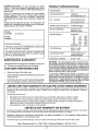
PRODUCT
CONGRATULATIONS
on your purchase of a Sears
Tractor° it has been designed, engineered and manufactured to give you the best possible dependability and
performance_
Should you experience any problem youcannot easily
remedy, please contact your nearest Sears Service
CentedDepartmento
We have competent, well-trained
technicians and the proper tools to service or repair this
unit,
SPECIFICATIONS
HORSEPOWER:
12.0
GASOLINE CAPACITY:
5 QUARTS
UNLEADED REGULAR
OIL (1 QUART):
SAE 30 (ABOVE 32°F)
5W-30 (BELOW 32°F)
Please read and retain this manual° The instructions will
enable you to assemble and maintain your unit properly.
Always observe the SAFETY RULES ,,
MODEL
NUMBER
917,255160
SPARK PLUG (GAP+030IN ):
CHAMPIONRL86C
VALVE CLEARANCE:
INTAKE ,002 IN
EXHAUST ,,004IN
GROUND SPEED:
FORWARD
tst
1 10
2nd
2 00
3rd
300
4th
4,20
5th
5 00
REVERSE: 1 50
SERIAL
NUMBER
DATE OF PURCHASE
THE MODEL AND SERIAL N UMBERS WILL BE FOUND
ON A PLATE UNDER THE SEAT.
YOU SHOULD RECORD BOTH SERIAL NUMBER AND
DATE OF PURCHASE AND KEEP IN A SAFE PLACE
FOR FUTURE REFERENCE.
MAINTENANCE
AGREEMENT
RESPONSIBILITIES
•
Read and observe the safety rules+
°
Follow a regular schedule in maintaining, caring for and
using your unit,
Follow the instructions under "Customer ResponsibilF
ties" and "Storage" sections of this owner's manual,
LIMITED ONE YEAR WARRANTY
TIRE PRESSURE:
FRONT: t4 PSI
REAR: 12 PSI
CHARGING SYSTEM:
5 AMPS HEADLIGHTS
3 AMPS BATTERY
BLADE BOLTTORQUE:
30+35 FT LBS
WARNING: Th!s unit is equ!pped with an internalcombus +
tion engine ano should not be use{] on or near any unimproved forest-covered t brush-covered or grass-covered
land unless the engine s exhaust system is equipped with
a spark arrester meeting applicable local or state laws {if
any)_ tf a spark arrester Jsused, it should be maintained =n
effective working order by the operator..
In the state of California the above is required by law
(Section 4442 of the California Public Resources Code).
Other states may have similar laws, Federal laws apply on
federal land& A spark arrester for the muffler is available
through your nearest Sears Authorized Service Center
(See REPAIR PARTS section of this manual),
A Sears Maintenance Agreement is available on this product, Contact your nearest Sears store for details.
CUSTOMER
MPH
MPH
MPH
MPH
MPH
MPH
ON ELECTRIC
START RIDING EQUIPMENT
For one (1) year from the date of purchase, if this riding equipment is maintained, lubricated and tuned up according to the
instructions in the owner's manual, Sears wil! repair or replace, free of charge, any parts found to be defective in material or
workmanship
This Warranty does not cover:
o
°
o
Expendable items which become wornduring normal use, such as blades, spark plugs, air cleaners and belts.
Tire replacement or repair caused by punctures from outside objects, such as nails,thorns, stumps, or glass.
Repairs necessary because of operator abuse, negligence, improper storage or accident or the failure to maintain the
equipment according to the instructionscontained in the owner's manual
=
Riding equipment used for commercial or rental purposes..
LIMITED 90 DAY WARRANTY
ON BATTERY
For 90 days from date of purchase, if any battery included with this riding equipment proves defective in material or workmanship
and our testing determines the battery will not hold-8 charge, Sears will replace the battery at no charge
WARRANTY SERVICE IS AVAILABLE BY RETURNING
CENTER!DEPARTMENT
IN THE UNITED STATES,
THE RIDING EQUIPMENT
TO THE NEAREST
SEARS SERVICE
This Warranty gives you specific legal rights, and you may also have other rights which may vary from state to state
Sear, Roebuck
and Co+, D/817 WA, Hoffman
3
Estates, IL 60179
U.S.Ao
TABLE OF CONTENTS
SAFETY RULES ............................................................
2
PRODUCT SPECIFICATIONS ...................................... 3
CUSTOMER RESPONSIBILITIES
................................ 3
WARRANTY ..................................................................
3
TABLE OF CONTENTS ................................................
4
INDEX ............................................................................
4
TRACTOR ACCESSORIES ..........................................
5
ASSEMBLY ................................................................
7-9
OPERATION ..........................................................
10-13
CUSTOMER RESPONSIBILITIES
......................... 14-17
SERVICE AND ADJ USTMENTS ............................ 18-23
STORAGE ...................................................................
24
TROUBLESHOOTING
...........................................
25-26
REPAIR PARTS - TRACTOR ................. ,.............. 28-45
REPAIR PARTS - ENGINE .................................... 46-49
PARTS ORDERING/SERVICE
.................. BACK PAGE
iNDEX
A
Accessories ................................................5
Adjustments:
Brake ............................................ 21
Carburetor ...........................................
24
Mower
Front-To-Back .......................... 19
Side-To-Side ............................ 18
Throttle Control Cable ..............i .o._24
Air Fitter, Engine ................................ 16
Ai_ Screen, Engine .............................. 16
Assembty ........................................... 7-9
B
Battery:
Charging ......................................
8
Cleaning ..............................
16
Installation ...................................... 9
Levels
8,16
Preparation .................................
8
Starting with Weak Battery ............22
Storage
25
Terminals ..........................................16
Belt:
Motion Drive
Removal/Replacement
............ 2I
Mower Blade Drive
Removal/Replacement
............ 20
Blade:
Sharpening
..............................
t5
Replacement ..............................
15
Brake Adjustment ................................... 21
.................................
..............................................
C
Customer Responsibilities ............ 14-17
Air Filter ........................................ 16
Air Screen, Engine ...........................16
Battery ......................................... 16
Blade .....................................................
15
Cooling Fins, Engine .................... 17
Engine 0il ....................................... 16
Fuel Filtel ....................................... 17
Lubrication Chart ......................... 14
Schedule ...........................................14
Spark Plugs .................................... 17
Tire Care ................................ 8,15,22
Carburetor Adjustment .....................
23
Controls, Tractor
.............................
10
Cutting Height, Mower ....................... 11
E
Electrical:
Operation .........................................
10-13
Operating Mower .....................................
12
Options:
Accessories .....................................
5
Spark Arrester ......................
3,38
Interlocks and Relays ................... 22
Schematic ....................................... 29
Wiring Diagram ........................... 30
Engine:
P
Air Filter ........................................... 16
Air Screen ....................................... 16
Parking Brake ................................ 10-11
Cooling Fins, Engine ...............
17
PartsBag ................................
6
Oil Change .......................................
16
Parts, Replacement/Repair
28-49
OilLevel
12,16
Product Specifications ............................. 3
Oil Type
16
Preparation ...............................
12
R
Repair Parts ..............................
46-49
Starting ........................................ 13
Repair Parts ........................................30_51
Storage ..................................
24
................
...................................
...........................................
S
F
Safety Rules ........................................
2
Filter:
Seat ....................................
8
Air Filter ............................................16
Service and Adjustments .............. 18-23
Fuel ................................................. 17
Carburetor ....................................... 23
Fuel:
Fuse ................................
22
Type ................................................
12
Hood Removal/Installation
.............22
Storage .......................................
24
Motion Drive Belt
Fuse .......................................................
22
Removal/Replacement
.............20
Mower Blade Drive Belt
H
Removal/Replacement
........... 20
Hood Removal/Installation
.................. 22
Mower Adjustment
Front- to-Back .......................... 19
Side-to-Side .............................. 18
L
Mower
Removat ..............................18
Leveling Mower Deck ................... 18-19
Tire Care ......................................
8,15,21
Lubrication:
Slope Guide Sheet ................................ 51
Chart..................................................
14
Spark Plugs ............................................. 17
Specifications ............................................. 3
M
Starting the Engine ........................ 12-13
Mower:
steering Wheel ................................... 7,21
Adjustment, Front-to-Back .......... 19
Stopping the Tractor
11
Adjustment, Side4o-Side ...............18
Storage ................................................ 24
Blade Sharpening ..............................
16
...............................
Blade Replacement ....................... 15
T
Cutting Height ................................
11
Throttle Control Cable
Installation ...................................... 18
Adjustment ..........................................
23
Operation
t2
Removal ........................................
t8
Tires ......................................................
8,15,21
Mowing Tips ........................................... 13
Trouble Shooting Chart ................... 25-26
Muffler ..................... :............................. 17
Transaxle:
Spark At rester ...................
338
Repair Parts .............................. 44-45
.........................................
O
Oil:
Cold Weather Conditions ..... 12,16
Engine ........................................
16
Storage .............................................24
4
W
Warranty ............................................
3
Wiring Diagram
30
Wiring Schematic
................................ 29
......................................
ACCESSORIES
i, ii
i
AN
ii
,,,i,
ATTACHMENTS
ii
....................
i iii1,11
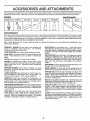
These accessories and attachments were available when the tractor was purchased. They are also available at most Sears retail outIets,
catalog and service centers. Most Sears stores can order these items for you when you provide the model number of your tractor°
ENGINE
SPARK PLUG
MAINTENANCE
MUFFLER
AIR RLTER
GAS CAN
ENGINE OIL
STAB|UZER
BLADES
BELTS
PERFORMANCE
Sears offers a wide variety of attachments that fit your trastor,. Many of these are listed below with brief explanations of how they can help
you. This list was current at the time of publication; however, it may change in future years - more attachments may be added, changes
may be made in these attachments, or some may no longer be avai{able or fit your me:teL Contact your nearest Sears store for the
accessories and attachments that are available for your tractor,
Most of these attachments
attaching and detaching.
do not require additional hitches or conversion kits (those that do are indicated) and are designed for easy
PERMANEX
BAGGER lets you collect grass clippings and
leaves for a healthier, nester looking Iawm Two Permanex
containers hold 30-gallon plastic bags.
LAWN SWEEPERS
let you collect grass clippings and ieavaso
LAWN VACS for powerful collection of heavy grass clippings and
leaves° Wand attachment to pick up debris in hard-to-reach
places°
CARTS make hauling easy. Variety of sizes available.
ROLLER for smoother lawn sudace,
36-inch wide, 18-inch
dtameterwater-t[ght drumholds upto3901bs, ofweighto Rounded
edges prevent harm to tuff
Adjustable scraper automatically
cleans drum.
SPREADERtSEEDERS
killing easy. Broadcast
de-icers and sand.
SNOW BLADE for snow removal only. 14-inch high, 42-inch
wide blade clears 38-inch path when angled left or right, Raises,
lowers with side lever. Adjustable skids; rejolaceabte,reversible
scraper bar. (Use with tire chains, wheel weights, or rear drawbar
weighL)
SNOWTHROWER has 40-inch swath° Drum-type auger handles
powdery and wet/heavy snow. Mounts easily with simple pin
arrangement.r Discharge chute adjusts from tractor seat° 6-inch
diameter spout discharges snow 10 to 50 feet° Lift controlled at
tractor seat. (Use with chains, wheel weights, or rear drawbar
weight°)
TIRE CHAINS are heavy duty; closely spaced extra-large cross
links give smooth ride, outstanding traction°
make seeding, fertilizing, and weed
spreaders are also useful for granular
WHEEL WEIGHTS for rear wheels provide needed traction for
snow removal or dozing heavy materials In pairs. (30 Ibs each.)
CORING AERATOR takes small plugs out of soil to allow moisture and nutrients to reach grass roots
36-inch swath_ 24
hardened steel coring tips. 150 tb. capacity weight tray_
TRACTOR CAB has heavy duty vinyl fabric over tubular steel
frame, ABS plastic top; clear plastic windshield offers 360 degree
visibitity_ Hinged metal doors with catch. Keeps operator warm
and dry. Remove vinyl and windshields for use as sun protector
in summer. (Catalog only.)
AERATOR promotes deep root growth for a healthy lawn. Tapered 2.5-inch steel spikes mounted on 10-inch diameter discs
puncture holes in soil at close intervals to let moisture soak in
Steel weight tray for increased penetration.
MULCH RAKE/DETHATCHER
loosens soil and flips thatch and
matted leaves to lawn surface for easy pickup Twenty spring tine
teeth° Usefultopreparebare
areasforseeding.
Availableforfront
or rear mounting.
SPRAYERS use 12-vott DC electric motor that connects to the
tractor battery or other 12-volt source.
Includes booms for
automatic spraying when pulling, and hand held wand for spot
spraying_ Wand has adjustable spray pattern° For applying
herbicides, insecticides, fungicides, and liqu d fertilizers.
Optional accessories for tractor cab: tinted/tempered solid
safety glass windshield with hand operated wiper; 12-vott amber
caution light for mounting on cab top° (Catalog only.)
TRACTOR COVER protects tractor from weather° Made of
Evolution 3 fabric (water-repellent, extremely breathable, light
weight, soft, non-abrasive pliable in all temperatures, durable,
sta n/tear/puncture resistant, will not shrink or stretch.) (Catalog
only..)
TILLER has 5 hp engine and 36-inchswath to prepare seed beds,
cultivate, and compost garden residue. Tiller has its own built-in
lift and depth control system and does NOT require asleeve hitch.
Fits any lawn, yard, or garden tractor. Simply hook up to the
tractor drawbar and go!
.........................
I'M'UUU
CONTENTS
....................
nlnnl
ii n i,
i,,
i
inn
IIInUIIlU
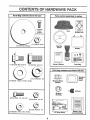
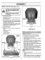
Parts Bag contents
ii, ii
iiiii
ii
i
"
I .....
i
i
......
II U I= .................
PACK
..........................................
.........................
ii iii
'
OF
n
i' i
i,l,,u,
j[i,ii,,u,,, i
I
Parts packed separately in carton
shown full size
i
,,
iiiiii1,1,1
Metal
(2)
Sor'ews
Sheet
x 1/2
Seat
Battery acid
(1) Locknut 3/8-24
Steering
Wheel
(1) 2-3/8" Di& Washer
i
Battery
Steering
Boot
(1) Shoulder Bolt 5/16-18
Owner's Manual
(1) Hex Bolt 1t2-13 x 1
Parts Bag
u,,nu i
Parts bag contents not shown full size
{1) Lock Washer
(1) Washer
inlnlinl I
]/ i
............
:
<_(2)
@
(2) Hex Bolts 1/4 - 20 x 3/4
I
Steering Wheel
Adapter
17/32 x 1-3/16 x 12 Ga.
iiii1,111
Wheel
Insert
teering
112
Keys
Steering
Bushing
-_ ........
(2) Hex Nuts 114 - 20
=j"
i
(2) Lock Washers
(2) Washers
1/4
9/32 x 5/8 x 16 Ga_
15 ° Slope Sheet
iql
6
,,i
,i
Battery Caps
and lnstructmns
,,,i,,,
i
,
,
_
...............
i , i i ,_,u,,.i,,.,_,_,Li,,
,=....
' ' I''""1 ......
M
..........
I' "11........
_;;;,;_,;,;,,;_,,;,_
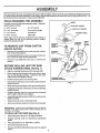
Your new tractor has been assembled at the factory with exception of those parts left unassembled for shipping purposeso
To ensure safe and proper operation of your tractor, all parts and hardware you assemble must be tightened securely_ Use
the correct tools as necessary to insure proper tightness.
TOOLS REQUIRED
FOR ASSEMBLY
INSERT
A socket wrench set will make assembly easier° Standard
wrench sizes are listed,,
(1) 5/16" wrench
(1) 3/4" wrench
(2) 7/16" wrenches
('1) 1/2" wrench
Tire pressure gauge
Screwdriver
(1) 9/16" wrench
Utility knife
_
,i LARGEFLATWASHER
When right and left hand is mentioned in this manual, it
means when you are in the operating position (seated
behind the steering wheel).
RINGWHEEL
\
_y_LJ"
SCREW
,
Remove all accessible loose parts and parts cartons
from carton (See page 6).
•
Cut along dotted lines on carton, from top to bottom, all
four corners of carton and lay panels flaL
•
Check for any additional
remove,,
BEFORE ROLLING
STEERING
STEERING
STEERING
loose parts or cartons and
SHEET
/
I
CARTON
•
ATTACH
_
WHEEL
ADAPTER
TO REMOVE UNiT FROM CARTON
UNPACK
3/8_24 HEX LOCKNUT
TABS
_
SHAFT
_
_
''
TAB
HOLE
POSITION)
UNiT OFF SKID
WHEEL
(See Fig. 1)
=
Slide the steering bushing over the steering shaft.
-
Raise steering shaft forward until screw holes in dash
line up with steering bushing
Install two (2) sheet
metal screws and tighten securely..
o
Position steering boot over steering shaft_
°
Place tabs of steering boot over slots in dash and push
down to secure.
o
Slide steering wheel adapter onto upper steering shaft,
•
Position front wheels of the tractor so they are pointing
straight forward.
°
Position steering wheel so cross bars are horizontal
(left to right) and slide onto adapter°
°
Assemble large flat washer and 3/8-24 hex Iocknut and
tighten securely°
o
Snap insert into center of steering wheel°
•
Remove protective plastic from tractor hood and grill,
TABSLOT
t
STEERING
(SHIPPING
UNIT OFF SKID (See Fig. 6)
•
Raise attachment lift lever to its highest position.
•
Release parking
pedal
•
•
Place gearshift lever in "NEUTRAL" position,
Roll unit backwards off skid.
=
Remove banding holding discharge guard up against
tractor.
brake by depressing
"_
FIG. 1
IMPORTANT: CHECK FOR AND REMOVE ANY STAPLES
iN SKID THAT MAY PUNCTURE TIRES WHERE UNIT IS
TO ROLL OFF SKID°
TO ROLL
SHAFT
POSITION)
clutch/brake
7
'
HOW TO SET UP YOUR TRACTOR
INSTALL
PREPARE
Adjust seat before tightening adjustment bolt,
BATTERY
CAUTION:
(See Fig. 2)
Wear eye and face shield.
Wash hands or clothing immediately if
accidentally in contactwith batteryacid,
Do not smoke.
Fumes from charged
battery acid are explosive.
Read the instructions included with the
battery vent caps. Always wear gloves,
clothing and goggles to protect your
hands, skin and eyes.
Your unit has a battery charging system which is sufficient
for normal use_ However', periodic chargin.g ' of the battery
with an automotive charger will extend its life_
•
See instructions packed with vent caps in parts bag°
o
Fill battery with acid. Fill each cell until it reaches the
bottom of the vent wells Do not overfill.
•
Allow battery to stand and settle for at least thirty
minutes After' standing, check the level of acid.. If
below the vent wells, add more acid until the correct
level is reached.
o
Remove cardboard packing on seat pan.
=
Place seat on pan and assemble shoulder bolt.
o
Assemble adjustment bolt, tockwasher and flat washer
loosely Do not tighten
o
Tighten shoulder bolt securely°
°
•
Lower seat into operating position and sit on seat.
Slide seat until a comfortable position is reached
which allows you to press clutch/brake pedal all the
way down (See Fig 6).
•
Get off seat without moving its adjusted position°
°
Raise seat and tighten adjustment bolt securely.
SEAT
SEAT PAN
SHOULDER
BOLT
While battery is standing (after adding acid) and later, while
battery is being charged, continue with assembly of unit.
IMPORTANT:
TO MAXIMIZE THE LIFE OF YOUR
BATTERY, IT IS NECESSARY THAT THE BATTERY BE
CHARGED
BEFORE USE FAILURE TO CHARGE
BATTERY CAN RESULT IN A SHORTENED BATTERY
LIFE.
•FLAT WASHER
ADJUSTMENT
o
Charge battery at a rate of 6 amperes for 1 hour. Use
a 12 volt battery charger. Observe all safety precautions required for' battery charging.
BOLT
.
Check the acid level afterthe battery is charged, tf the
acid has fallen below the correct level, add distilled or
iron free water'.
CHECK
o
Check battery case for leakage to make sure that no
damage has occurred in handling.
o
Dispose of excess battery acid. Neutralize acid for
disposal by adding it to four inches of water' in a five
gallon plastic container. Stir with a wooden or plastic
paddle while adding baking soda until the addition of
more soda causes no more foaming.
°
TIRE PRESSURE
The tires on your unit were overinflated at the factory for
shipping purposes° Correct tire pressure is important for
best cutting performance_
•
Reduce tirepressure
to PSI shown in "PRODUCT
SPECIFICATION S" on page 3 of this manual.
CHECK DECK LEVELNESS
For best cutting results, mower housing should be properly
leveled.. See "TO LEVEL MOWER HOUSING" in the
Service and Adjustments section of this manual
Follow instructions on how to install battery.
CHECK
BELTS
VENT CAP
CUT AWAY VIEW
LOCK WASHER
FIG. 3
install the vent caps to cover the vent wells. Wash the
top of the battery with water to remove any acid, then
w_pedry°
o
SEAT (See Fig. 3)
FOR
PROPER
POSITION
OF
ALL
See the figures that are shown for replacing motion and
mower blade drive belts in the Service and Adjustments
section of this manual. Verify that the belts are routed
correctly.
BATTERY
CELL ACID
LEVEL
FIG. 2
CHECK BRAKE SYSTEM
8
After you learn how to operate your tractor, check to see
that th_e.brake is properly adjusted See TO ADJUST
BRAKE in the Service and Adjustments section of this
manual..
BLY
INSTALL
BATTERY
(See Figs. 4 & 5)
CAUTION: Do not short battery terminals. Before installing battery, remove
metal bracelets, wristwatch bands,
rings, etc.
Positive terminal must be connected
first to prevent sparking from accidental grounding,
, , p,
,
p
,I,.IIH
................
,
.11.1,.
,
Lift seat to raised position°
•
Open battery box door.
o
Lower battery into battery box with battery terminals
toward front of uniL
•
Be sure battery drain tube is attached to battery box.
,,
First connect RED battery cable to positive (+) battery
terminal with hexbolt, flat washer, lock washer and hex
nut as shown. Tighten securely.
Connect BLACK grounding cable to negative (-) battery terminal with remaining hex bolt, flat washer, lock
washer and hex nuL Tighten securely.
o
BATTERY
VENT CAPS
[
•
Close battery box door
FIG. 5
Open battery box door for:
•
Inspection for secure connections
ware).
=
Inspection for corrosion.
•
Testing battery.
°
,Jumping (if required)
•
Periodic charging.
(to tighten hard-
CHECKLIST
BEFORE YOU OPERATE AND ENJOY YOUR NEW
TRACTOR, WE WISH TO ASSURE THAT YOU RECEIVE
THEBESTPERFORMANCEAND
SA TISFACTION FROM
THIS QUALITY PRODUCT
PLEASE REVIEW THE FOLLOWING
BATTERY
BOX DOOR
NEGATIVE
POSITIVE
(BLACK)
RED) CABLE
HEX
BOLT
NEGATIVE
FIG. 4
,/
Al! assembly instructions have been completed.
,/
No remaining loose parts in carton°
,/
Battery is properly prepared and charged.
1 hour at 6 amps).
,/
Seat is adjusted comfortably and tightened securely.
,I
All tires are properly inflated,. (For shipping purposes,
the tires were over-inflated at the factory),
,/
Be sure mower deck is properly leveled side-to-side/
front-to-rear for best cutting results_ (Tires must be
properly inflated for leveling)_
,/
Check mower and drive belts. Be sure they are routed
properly around pulleys and inside all belt keepers.
,/
Check wiring. See that all connections are still secure
and wires are properly clamped,
(Minimum
CABLE
LOCK WASHER
POSITIVE (+) TERMINAL
CHECK!.IST:
(-) TERMINAL
WHILE LEARNING HOW TO USE YOUR TRACTOR, PAY
EXTRA ATTENTION TO THE FOLLOWING IMPORTANT
ITEMS.:
,/
Engine oil is at proper level.
J'
Fuel tank is filled with fresh, clean, regular unleaded
gasoline_
v"
Become familiar with all controls - their location and
function. Operate them before you start the engine.
,/
Be sure brake system is in safe operating condition.
i •
i, i
.....................................
i,, ii,
,.i,i, ,,
i,,,ll ....
,
,i,,,i,,
,i,,._,.,,,,,,,
.................
........................................
OPEFIATJON
.... u
ii..............
ii.....
iiiUll IIi
i
IIMIIII
iiuiiill i i
I
IIll
IIll
UIi I i
,r,,
KNOW YOUR TRACTOR
READ
THIS
OWNER'S
MANUAL
AND
SAFETY
RULES
BEFORE
OPERATING
YOUR
TRACTOR
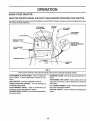
Compare the illustrations with yourtractorto familiarize yourself withtire iocationsof various controls and adjustments. Save
this manual for future reference.
ATTACHMENT
CLUTCH LEVER
IGNITION
SWITCH
LIFt' LEVER
PLUNGER
ATTACHMENT
LEVER
THROTTLE/CHOKE
CONTROL
MOWER DECK
HEIGHT ADJUSTMENT
POSITIONS
CLUTC H!BRAKE
PEDAL
PARKING
BRAKE
GEARSHIFT
LEVER
FIG. 6
IlL
ill
ill
l
Seats tractors conform to the safety standards of the American National Standards Institute_
ATTACHMENT CLUTCH LEVER: Used to engage the
mower blades, or other attachments mounted to your
tractor.
LIGHTSWlTGH:
Turnsthe
GEARSHIFT LEVER: Selects the speed and direction of
tractor+
ATTACHMENT LIFT LEVER: Used to raise, lower, and
adjust the mower deck or other attachments mounted to
your tractor.
LIFT LEVER PLUNGER: Used to release attachment lift
headlights on and off.
THROTTLE/CHOKE
CONTROL:
controlling engine speed.
Used for starting and
lever when changing its position.
CLUTCH/BRAKE
PEDAL:
Used for declutching and
braking the tractor and starting the engine.
PARKING BRAKE LEVER: Locks clutch/brake pedal into
the brake position.
IGNITION SWITCH:
engine_
10
Used for starting and stopping tile
OPERATION
The operation of any tractor can result in foreign objects thrown into the eyes, which can
result in severe eye damage. Always wear safety glasses or eye shields while operating
your tractor or performing any adjustments or repairs_ We recommend wide vision safety
mask for over the spectacles or standard safety glasses, available at Sears Retail or
Catalog stores.
HOW TO USE YOUR TRACTOR
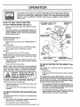
TO SET
PARKING
BRAKE
(See
ATTACHMENT CLUTCH LEVER
"ENGAGED" POSITION
Fig. 7)
•
Depress clutch/brake pedal into full "BRAKE" position
and hold.
o
Place parking brake lever in"ENGAGED" position and
release pressure from clutchYorake pedal Pedalshould
remain in "BRAKE" position_ Make sure parking brake
wilt hold vehicle secure_
IGNITION
KEY
PARKING
BRAKE
"ENGAGED"
POSITION
THROTTLF_JCHOKE
CONTROL LEVER "__
STOPPING
(See
MOWER BLADES*
GEAR
sHIFT
LEVER
po-
DRIVE -
Depress clutch/brake pedal into full "BRAKE" position°
o
Move gearshift
ENGINE
o
7)
Move attachment clutch lever to "DISENGAGED"
sition,
GROUND
o
Fig.
lever to "NEUTRAL" position
Move throttle control to "SLOW" position.
"BRAKE"
POSITION
NOTE: Failure to move throttle control to "SLOW" position
and allowing engine to idle before stopping may cause
engine to "backfire"
o
"DISENGAGED"
POSITION
CLUTCH/BRAKE PEDAL
"DRIVE" POSITION
Turn ignition key to "OFF" position and remove key.
Always remove key when leaving vehicle to prevent
unauthorized use°
PARKING BRAKE
"DISENGAGED" POSITION
FIG. 7
Never use choke to stop engine.
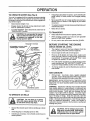
TO ADJUST MOWER CUTTING HEIGHT (See
Fig. 6)
NOTE: Under certain conditions when unit is standing ilde
with the engine running, hot engine exhaust gases may
cause "browning" of grass To eliminate this possibility,
always stop engine when stopping unit on grass areas_
The position of the attachment lift lever determines the
cutting height°
CAUTION:
Always stop unit completely, as described above, before
leaving the operator's
position;
to
empty grass catcher, etc.
•
Grasp lift lever°
•
Press plunger with thumb and move lever to desired
position•
Always operate engine at full throttle.
The cutting height range is approximately 1-1/4to 3_3/4".
The heights are measured from the ground to the blade tip
with the engine not running. These heights are approximate and may vary depending upon soil conditions, height
of grass and types of grass being mowed.
o
Operating engine at less than full throttle reduces the
battery charging rate,
o
o
Full throttle offers the best bagging and mower performance_
The average lawn should be cut approximately 2-1/2
inchesduring the cool season and over 3 inchesduring
hot months. For healthier and better looking lawns,
mow often and after moderate growth.
°
For best cuttingperformance,
grass over 6 inches in
height should be mowed twice. Make the first cut
relatively high; the second to desired height.
TO USE
THROTTLE
CONTROL
(See
Fig. 7)
TO MOVE FORWARD AND BACKWARD (See
Fig. 6)
The direction and speed of movement is controlled bythe
gearshift lever,
•
Start tractor with clutch/brake pedal depressed and
gearshift lever in "NEUTRAL" position,,
o
Move gearshift
o
Slowly release clutch/brake pedal to start movement°
lever to desired position,.
11
OPERATIC
_,,i
','
,,, ,...........
TO OPERATE
..................................................................
MOWER
'..................
(See Fig. 8)
Your' unit is equipped with an operator presence sensing
switch Any attempt by the operator to leave the seat with
the engine running and the attachment clutch engaged will
shut off the engine.
-
Select desired height of cut,
•
Engage mower by slowly moving attachment clutch
lever to "ENGAGED" position_
TO STOP MOWER - Move attachment clutch lever to
"DISENGAGED" position.
•
_
CAUTION: Do not operate the mower
without either the entire grass catcher,
on mowers so equipped, or the discharge guard in place.
If stopping is absolutely necessary, push clutch!brake
pedal quickly to brake position and engage parking
brake.
=
Move gearshift lever to 1st gear and be sure you have
allowed room for tractor to roll slightly as you restart
movemenL
.
To restart movement, slowly release parking brakeand
clutch!brake pedal°
=
Make all turns slowly,
TO TRANSPORT
|
I
"ENGAGED ='POSITION
ATTACHMENT CLUTCH LEVER
"DISENGAGED"
POSITION
•
•
Raise attachment lift control to highest position
•
When pushing or tow!rig your unit, be sure gearshift
lever is in NEUTRAL position.
•
Do not push or tow unit at more than five (5) MPH.
BEFORE
CHECK
ATTACHMENT
LIFT LEVER
HiGH POSITION
LOW POSITION
STARTING
THE ENGUNE
ENGINE OIL LEVEL
o
The engine in your unit has been shipped, from the
factory, already filled with summer weight oil.
.
Check engine oil with unit on level ground°
o
Remove oil fill dipstick and wipe clean, replace and
screw cap tight, wait for a few seconds, remove and
read oil level If necessary, add oil until "FULL" mark
on dipstick is reached,, Do not overfill..
.
For cold weather operation you should change oil for
easier starting (see "OIL VISCOSITY CHART' in the
Customer Responsibilities section of this manual).
•
To change engine oil, see the Maintenance section in
this manual.
ADD GASOLINE
°
Fill fue! tank. Use fresh, clean, regular unleaded
gasoline. (Use of leaded gasoline will increase carbon
and lead oxide deposits and reduce valve life)o
IMPORTANT: WHEN OPERATING IN TEMPERATURES
BELOW 32°F(0°C), USE FRESH, CLEAN WINTER GRADE
GASOLINE TO HELP INSURE GOOD COLD WEATHER
STARTING,,
R.H.
INER
D|SCHARGE
WARNING:
Experience indicates that alcohol blended
fuels (called gasohol or using ethanol or methanol) can
attract moisture which leads to separation and formation of
acids during storage. Acidic gas can damage the fuel
system of an engine while in storage° To avoid engine
problems, the tuel system should be emptied before storage of 30 days or longer. Drain the gas tank, start the
engine and let it run until the fuel lines and carburetor are
empty. Use fresh fue! next season, See Storage Instructions for additional information,. Never use engine or
carburetor cleaner products in the fuel tank or permanent
damage may occur.
GUARD
FIG. 8
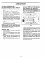
TO OPERATE
i,
ON HILLS
CAUTION:
Do not drive up or down
hills with slopes greater than 15 0 and
...... do,,r,,not drive across any ,,_,r
I
slope. ''"'11'1'1 '1111'1'
1_
,
i
i.ii, ,111,,i,i
,,
,,,,,,,i,,i,
i,,i,
I
,i,ii
Q
Choose the slowest speed before starting up or down
hifls_
O
Avoid stepping or changing speed on hills.
@
If slowing is necessary, move throttle control lever to
slower position.
I _
I _
12
A
filler neck. Do notoverfiil. Wipe offany
spilledoitorfuel.
Do not store, spUlor
use gasoline near an open flame.
i
|
OPERATUO
TO START
ENGINE
(See Fig. 7)
When starting engine for the first time or if engine has
run out of fue!, it will take extra cranking time to move
fuel from the tank to the engine°
o
Depress the clutch/brake
brake°
pedal and set the parking
•
Place gearshift lever in "NEUTRAL"
o
Move attachment clutch to "DISENGAGED"
o
Move throttle control lever to "CHOKE" position for
cold engine start.
For warm engine start, move
throttle control to "FAST" position.
•
Turn ignition key clockwise to "START" position and
release key as soon as engine starts. Do not run
starter continuously, for more than fifteen seconds
per minute. If engine does not start after several
attempts, move throttle control to "FAST" position,
wait a few minutes and try again..
o
Drive so that clippings are discharged onto the area
that has been cut° Have the cut area to the right of
the machine. This will result in a more even distribution of clippings and more uniform cutting.
o
When mowing large areas, start by turning to the
right so that clippings will discharge away from
shrubs, fences, driveways, etc. After one or two
rounds, mow in the opposite direction making left
hand turns until finished(See
Fig. 9),
position.
position.
•
When engine starts, move throttle control to desired
position.
•
Allow engine to warm up for a few minutes before
engaging drive or attachment clutch.
NOTE: If at a high altitude (above 3000 feet) or in cold
temperatures (below 32 ° F), the carburetor fuel mixture
may need to be adjusted for best engine performance.
See "TO ADJUST CARBURETOR" in the Service and
Adjustments section of this manual
FIG. 9
•
If grass is extremely tall, it should be mowed twice
to reduce load and possible fire hazard from dried
clippings. Make first cut relatively high; the second
to the desired height.
MOWnNG TBPS
o
Tire chains cannot be used when the mower housing is attached to unit°
°
,
Mower should be _roperly leveled for best mowing
performance. See TO LEVEL MOWER HOUSING
m the Service and Adjustments section of this
manual
Do not mow grass when it is weL Wet grass will
plug mower and leave undesirable clumps. Allow
grass to dry before mowing.
•
Always operate engine at full throttle when mowing
to assure better mowing performance and proper
discharge of material. Regulate ground speed by
selecting a low enough gear to give the mower
cutting performance as well as the quality of cut
desired°
°
When operating attachments, select a ground speed
that will suit the terrain and give best performance of
the attachment being used°
•
Use the runner on the right hand side of mower as
a guide.
The blade cuts approximately an inch
outside the runner (See Fig° 8)..
•
The left hand side of mower should be used for trimming..
13
CUSTO
,
i.....
RESPO
,,,,,,...............................
MAINTENANCE
,,
SCHEDULE
a
Sha'penlReplace Mower Blades
Lubrication Chart
6##
_
_"
_,_"
E DATE S
.....
1
C 1.C.hec.
k Battery Leve,/Recharge
O
_/,_t.
._'_4_'#'SERVIC
Check B,_akeOperation
Check Tire Pressure
Check for Loose Fasteners
.....
_'_
/_.,_
As COMPLETE
T
,,, ,, ,,,,,
_'___o_
FILL IN DATES
, REGULAR SERVICE
,,,,,,,,
¢
....
! v' .......
Clear! Battery and Ter.minais
Check Transmission Cooling
e,'
Adjust Blade Belt(s) Tension
¢5
Adjust Motion Drive Belt(s) Tension
.........Check Engine (_'iiLevel .........
v'
6/
,,¢ ,,, _,3
Change Engine 0ii
Clean Air Screen ..................
1
,
v'
Replace OiIFitter (If equipped)
clean Engine Cooling Fins
Replace Spark Plug
.................
,
e#'2
G 1 Inspect MuffledSpark Attester
E
V'.
¢2
Clean Air Filter
,,,,
[
......_/_
....
Replace Air Filter Paper Cartridge
Replace Fuel Filter
, ,,,,.
1 - Change mere often when operating under a heavy load or in high ambient
2 - Service more often when operating in dlrty or dusty eendilions
GENERAL
_,emperatures
3 - If equipped with el! filter, change el! ever'i 50 hours
4 - Replace blades more otten when mowing in sandy soil
5 - If equipped with adiustable system
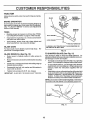
LUBRICATION
RECOMMENDATIONS
The warranty on this tractor does not cover items that have
been subjected to operator abuse or negligence.
To
receive full value from the warranty, operator must maintain
tractor as instructed in this manual°
(_)
SPINDLE
CHART
ZERK -':,._-'__r----*
::::::::::::
(_) FRONT WHEEL ""_
Some adjustments will need to be made periodically to
properly maintain your tractoL
BEARING
:i t_
ZERK(_IJL,
BEARING
ZER
®
Once a year you should replace the spark plug, clean
or replace air filter, and check blades and belts for
wear. A new spark plug and clean air filter assure
proper air-fuel mixture and help your engine run better
and last tongeL
BEFORE
FRONT WHEEL
ENGINE _)
All adjustments in the Service and Adjustments section of
this manual should be checked at least once each season.,
.
SPINDLE ZERK (_
CLUTCH
PIVOT(S)
EACH USE
o
Check engine oi! level..
•
Check brake operation.
•
•
Check tire pressure
Check for loose fasteners.
(_SAE
30 OR 10W30 MOTOR OIL API - SG
(_) GENERAL
PURPOSE GREASE
(_) REFER TO CUSTOMER RESPONSIBILITIES
"ENGINE"
SECTION
IMPORTANT:
DO NOT OIL OR GREASE THE PIVOT POINTS
WHICH HAVE SPECIAL NYLON BEARINGS
VISCOUS LUBRICANTS WILL ATTRACT
DUST AND DIRT THAT WILL SHORTEN
THE LtFE OF THE SELF-LUBRICATING
BEARINGS
IF YOU
FEEL THEY MUST BE LUBRICATED,
USE ONLY A DRY, POWDERED GRAPHITE
TYPE LUBRICANT
SPARINGLY.
14
......
,, ,,,,,,,,,,,,,,,, ......
i ,,, i1,1,,i,ii1,¸,,111
,r,,r,,r,,,L
CUSTOME
; ,,;,;,,;,,,,
..............
i ........
BILITIES
,.............
TRACTOR
Always observe safety rules when performing any mainte-
_"_
nance,
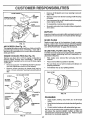
BRAKE
MANDREL
OPERATION
If unit requires more than six (6) feet stoppingdistance at
high speed in highest gear, than brake mustbe adjusted°
(See "TO ADJUST BRAKE" in Service and Adjustments
section of this manual)
%_
TIRES
•
Maintain proper air pressure in all tires (See "PRODUCT SPECIFICATIONS" on page 3 of this manual).
•
Keep tires free of gasoline, oil, or insect control chemicals which can harm rubber.
o
Avoid stumps, stones, deep ruts, sharp objects and
other hazards that may cause tire damage.
BLADE
EDGE UP
4;
FLATWASHER
_
_
/
,.OCKWAS.ER--'----'--"
'
HEX BOLT (GRADE 8)*
"A GP,ADE 8 HEAT TREATED BOLT CAN BE IDENTIFIED
SiX LINES ON THE BOLT HEAD.
CARE
For best results mower blades must be kept sharp°
place bent or damaged blades.
_
BY
ReFIG. 10
BLADE REMOVAL (See Fig. 10)
TO SHARPEN BLADE (See Fig. 11)
.
Raise mower to highest position to allow access to
blades,.
=
Remove hex bolt, {ockwasher andflat washersecudng
blade_
Care should be taken to keep the blade balanced. An
unbalanced blade will cause excessive vibratio nand eventual damage to mower and engine.
°
Install new or resharpened blade with trailing edge up
towards deck as shown°
°
Reassemble hex bolt, lock washer and flat washer in
exact order as shown,
o Tighten bolt securely (30-35 Ft. Lbsotorque).
IMPORTANT: BLADE BOLT IS GRADE 8 HEAT TREATED.
•
The blade can be sharpened with afire or ona grinding
wheel Do not attempt to sharpen while on the mower.
°
To check blade balance, you will need a 5/8" diameter
steel bolt, pin, or a cone balancer. (When using a cone
balancer, follow the instructions supplied with balancer) o
•
Slide blade on to an unthreaded portion ofthe steel bolt
or pin and hold the bolt or pin parallel with the ground.
If blade is balanced, it should remain in a horizontal
position° If either end of the blade moves downward,
sharpen the heavy end until the blade is balanced.
NOTE- Do not use a nail for balancing blade. The lobes of
the center hole may appear to be centered, but are not,.
CENTER HOLE
518" BOLT__
/
_/
FIG. 1'1
15
/
BLADE
ENGINE
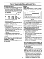
BATTERY
(See Fig. 12)
Your unit has a battery charging system which is sufficient
for normal use,, However', periodic charging of the battery
with an automotive charger will extend it's life_
o
Acid solution level in each battery cell should be even
withbottomsofventwells,.
Add onlydistUled or iron free
water' if necessary, Do not overfillo
LUBR|CATtON
Only use high quality detergent oil rated with API service
classification SG Select the oil's SAE viscosity grade
according to your expected operating temperature_
SAE VISCOSITY GRADES
CUT AWAY VIEW
WELL
=F
BATTERY
CELL ACID
LEVEL
C
-20 _
0°
30_
32_ 40_
60_
-_0"
*20_
-10 _
0_ 2.w_ 16_
TEMPERATURE
RANGE ANTICIPATED
BEFORE
80°
100 _
0_.....
3_
NEXT OIL CHANGE
40_
FIG. 13
FIG. 12
o
o
•
•
TO
NOTE: Although rnuiti-viscosity oils (5W30, 10W30 etc.)
improve starting in cold weather, these rnulti-viscosityoils
will result in increased oil consumption when used above
32°F. Check your engine oil level more frequently to avoid
possible engine damage from running low on oil
Change the oil after the first two hours of operation and
every 25 hours thereafter or at least once a year if the
tractor is not used for 25 hours in one year
Keep battery and terminals clean,
Keep battery bolts tight.
Keep vent caps tight and small vent holes in caps open_
Recharge at 6 amperes for' 1 hour,.
CLEAN BATTERY AND TERMINALS -
Corrosion and dirt on the battery and terminals can cause
_he battery to "leak" power.
Remove terminal guard,
= Disconnect BLACK battery cable first then RED battery cable and remove battery from tractor,
•
Wash battery with solution of four tablespoons of
baking sodato one gallon of waterr Be careful not to get
the soda solution into the cells.
•
Rinse the battery with plain water and dry.
= Clean terminals and batterycable ends with wire brush
until brighL
= Coat terminals with grease or petroleum jelly.
o
Reinstall battery (See "INSTALL BATTERY" in assembly section of this manual)..
V-BELTS
Check V-Beits for deterioration and wear after 100 hours
and replace if necessary, The nlotions drive belt is not
adjustable. Replace belts if they begin to slip from wear'.
TRANSAXLE
Check the crankcase oil level before starting the engine
and after each eight (8) hours of continuous use.
TO CHANGE ENGINE OiL (See Figs 13 & 14)
Determine temperature range expected before oil change°
All oil must meet AP1 service classification SG
°
Be sure vehicle is on level surface
o Oil will drain more freely when warm.
•
Catch oil in a suitable container,,
•
Remove oi! fill dipstick. Be careful not to allow dirt to
enter the engine when changing oiL
o Removedram plug.
° After oil has drained completely, replace oil drain plug
and tighten securely.
°
Refill engine with oilthrough oil fill dipstick tube. Pour
slowly, Do not overfill For approximate capacity see
Product Specifications on page 3 of this manual
o UsegaugeonoilfilldipstickforcheckingleveL
Besure
dipstick cap is tightened securely for' accurate reading.
Keep oil at "FULL" line on dipstick.
COOUNG
Keep transaxle free from build-up of dirt and chaff which
can restrict cooling.
AIR RLTER FOAM PRE-CLEANER (See Fig. 14)
16
Your engine wilt not run properly and may be damaged by
using a dirtyairfilter_ Remove cartridge every25 hoursand
tap to clean° Replace paper cartridge once a year or after'
every 100 hour's of operation, more often if used in very
dusty, dirty conditions
•
Remove knobs and cover.
o Remove foam pre-cleaner element by sliding it off of
the paper cartridge,.
NOTE: Do not attempt to clean or oil the paper' cartridge.
Replace paper' cartridge once a year or after every 100
hours of operation; more often if used in very dusty or dirty
conditions.
o
Wash f°am pre'cleaner in liquiddetergent and water"
o
Wrap foam pre-cleaner in cloth and squeeze dry.
o
Lightly coat foam pre-cleaner with clean engine oil.
Squeeze in towel to remove excess oil Do not
saturate.
=
install foam pre-cleaner over paper cartridge.
o
Reassemble cover and tighten knobs securely.
i .....
i i i i i,,,i,i,,,,,,,,,,,11,i....
CUSTOM
!
ii
i , i
........
i,i,
PONSU
i,i1,11 ....................
iI
, i,
•
Remove oil fill dipstick and cover opening to prevent
entry of dirt.
o
Remove screws from blower housing and lift housing
off engine.
•
Use compressed air or stiff bristle brush to thoroughly
clean engine cooling fins.
o
To reassemble, reverse above procedure.
,
Be certain carburetor tube, breather tube and gaskets
are in place_
AIR
ENGINE OIL FILLER
CAP AND DIPSTICK
i, I,
AI}
MUFFLER
AIR
LEANER
BODY
Inspect and replace corroded muffler and spark arrester (if
equipped) as it could create a fire hazard and/or damage.
SPARK PLUGS
OIL DRAIN PLUG
Replace spark plugs at the beginning of each mowing
season or after every 100 hours of use, whichever comes
first. Sparkplug type and gap setting is shown in "PRODUCT SPECIFICATIONS" on page 3 of this manual
FIG, 14
AIR SCREEN
(See Fig. 14)
The engine air screen must be kept free of dirt and chaff to
prevent engine damage from overheating., Clean with a
wire brush or compressed air to remove dirt and stubborn
dried gum fibers.
IN-LINE
FUEL FILTER
(See Fig. 16)
Fuelfilter should be replaced once each season, tffuelfilter
becomes clogged, obstructing fuel flow to carburetor, replacement is required.,
ENGINE
COOLING
FINS (See Fig. 15)
Remove any dust, dirt or oil from engine cooling fins to
prevent engine damage from overheating°
Hood and
engine blower housing must be removed to clean engine
cooling fins
.
Remove hood (see "TO REMOVE HOOD" in the Service and Adjustments section of this manual)_
•
Remove screws securing air cleaner body and remove. (Cover carburetor opening to prevent entry of
•
With engine cool, remove filter and plug fuel line
sections_
•
Place new fuel filter in position in fuel line.
°
Be sure there are no fuel line leaks and clamps are
properly positioned°
o
Immediately wipe up any spilled gasoline.
d rt)
FUEL FILTER
AIR CLEANER
COVER
SCREW ",--_,_
BLOWER
HOUSING
SCREWS
J
SCREW
GASKETS
COOLING
FIG. 16
BREATHER
TUBE
CYLINDER
HEAD
COVER
CLEANING
CARBURETOR
TUBE
SPARK
PLUG
.
Clean engine, battery, seat, finish, etc. of all foreign
matter.
o
Keep finished surfaces and wheels free of all gasoline,
oil, etco
o
Protect painted surfaces with automotive type wax
We do not recommend using a garden hose to clean your
unit unless the electrical system, muffler, air filter and
carburetorarecoveredto
keepwater OUtoWater in engine
can result in a shortened engine life,
MUFFLER
FIG. 15
17
SERVICE AN
ADJUSTMENTS
i=,l,,,,ll,,i
....
CAUTION:
=
....IN
BEFORE PERFORMING ANY SERVICE OR ADJusTMENTS;
=
Depress clutch/brake pedal fully and set parking brake.
o
°
Place gearshift lever in "NEUTRAL" position,
Place attachment clutch in "DISENGAGED"
position,
o
Turn ignition key"OFF" and remove key.
Make sure the blades and all moving parts have completely stopped,
e
Disconnect spark plug wire from spark plug and place wire where it cannot come in contact with
plug,
TRACTOR
TO REMOVE
CLUTCH
MOWER
ROD
CLUTCH LEVER
(See Fig. 17)
RETAINER
SPRING
Mower will be easier to remove from the right side of tractor,
=
o
Place attachment clutch in "DISENGAGED" position.
Moveattachmentliftleverforwardtolowermowertoits
lowest pesitionv
°
Roll bolt off engine putley.
o
Disconnect ctutch rod from clutch lever by removing
retainer spring.
•
Disconnect anti-sway bar' from chassis
removing retainer spring
=
Disconnect suspension arms from rear deck brackets
by removing retainer springs.
,,
Disconnect front links from deck by removing retainer
springs.
-
Raise lift lever to raise suspension arrns= Slide mower
out from under tractor.
SUSPENSION
ARMS
"'.
\
bracket by
MOWER
ANTFSWAY
BAR
RETAINER
SPRINGS
(BOTH SIDES)
(See Fig. 17)
,
Raise attachment lift lever to its highest position.
•
Slide mower under'tractor with discharge guard to right
side of tractor_
°
°
Lower lift lever to its lowest position.
Instal_ mower in reverse order of removal instructions.
RETAINER
SPRINGS
(BOTH SIDES
/
RETAINER
SPRING
IMPORTANT:
IF AN ATTACHMENT OTHER THAN THE
MOWER IS TO BE MOUNTED TO THE TRACTOR, THE
R.H. AND L H. SUSPENSION ARMS MUST BE REMOVED
FROM TRACTOR..
TO INSTALL
ENGINE
PULLEY
FIG. 17
18
i
i,i i,, i
,
i
ii iiiii ,,i,,11i,,ll,ll,llll,i
ii1,1,,11
RVICE AND ADJUSTMENTS
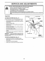
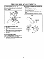
TO LEVEL MOWER
HOUSING
FRONT-TO-BACK ADJUSTMENT (See Figs. 20 and 21) IMPORTANT: DECK MUST BE LEVEL SIDE-TO-SIDE IF
THE FOLLOWING FRONT-TO-BACK ADJUSTMENT IS
NECESSARY, BE SURE TO ADJUST BOTH FRONT LINKS
EQUALLY SO MOWER WILL STAY LEVEL SIDE-TOSIDE..
To obtain the best cutting results, the mower housing
should be adjusted so that the front is approximately 1/4" to
3/4" lower than the rear when the mower is in its highest
position,.
Check adjustment on right side of tractor. Measure dis'
" front and behind
'
tance " D " d_rectly,n
the mandrel at bott om
edge of mower housing as shown°
Adjust the mower while tractor is parked on level ground or
driveway,
Make sure tires are properly inflated (See
"PRODUCT SPECIFICATIONS
on page 3). If tires are
over or under inflated, you will not properly adjust your
mower.
SIDE-TO-SIDE ADJUSTMENT (See Figs. 18 and 19) You will need two (2) standard 2 x 4 short pieces of wood
to make the following adjustment. Similar blocks measuring 1-t/2" thick may also be used°
°
Raise mower with attachment lift control to allow two
(2) 1-1/2" thick blocks to be placed under rear edge of
mower,
o
Place one block directly behind right mandrel° Place
the remaining block under the stamped ridge on left
side of rear edge of mower deck..
°
Before makingany necessary adjustments, checkthat
both front links are equal in length. Both links should
be approximately 10-3/8".
°
Lower mower deck to its lowest height of cut position
(See 'q'O ADJUST MOWER CUTTING HEIGHT" in
Operation section of this manual).
°
If links are not equal in length, adjust one link to same
length as other link.
To lower front of mower loosen nut "E" on both front
links an equal number of turns.
When distance "D" is 1/4" to 3/4" lower at front than
rear, tighten nuts "F" against trunnion on both front
links.
o
o
On both sides of tractor, loosen, but do not remove, the
fasteners securing the adjustable pivot brackets to
frame Both brackets must be loose enough to move
freely.
o
o
Pull down firmly on suspension arm to remove any
slack in pivot bracket and hold while tightening rear
fastener first to secure° Tighten remaining fastener.
°
o
Repeat procedure on other side of tractor..
o
o
Raise mower with attachment lift control and remove
blocks from under mower.
.
To raise front of mower, loosen nut"F" from trunnion on
both front links,. Tighten nut "E" on both front links an
equal number of turns..
When distance "D" is 1/4" to 3/4" lower at front than
rear, tighten nut "F" against trunnion on both front links,
Recheck side-to-side adjustment.
MANDREL
PLACE TWO (2) 1-1/2" THICK BLOCKS UNDER REAR EDGE OF
DECK (Use wood 2 x 4's or equivo)
/
FIG, 20
UNDER
STAMPED
BOTH FRONT LINKS MUST BE EQUAL
MOWER MUST BEIN LOWEST HEIGHT
IN LENGTH
OF CUT POSITION
FIG. 18
ADJUSTABLE
BRACKET
SUSPENSION
PIVOT
NUT"E"
ARM
NUT "F"_
FASTENER
FIRST
FRONT LINKS
TRUNNION
FIGo 19
19
FIG. 21
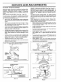
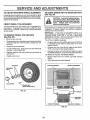
TO REPLACE
MOWER
BLADE
DRIVE BELT
(See Fig. 22)
The mower blade drive belt may be replaced without
tools. Park the tractor on level surface. Engage parking
brake. For assistance, there is a belt installation guide
decal on the mower housing.
BELT REMOVAL o Place attachment clutch in "DISENGAGED" position.
o Move attachment lift lever forward to lower mower' to
its lowest position.
o
Roll belt off engine pulley_
•
Disconnect R_H,. suspension arm from
bracket by removing retainer spring,
rear deck
o
Work belt off both mandrel pulleys and idler pulleys.
o
Pull belt away from mower°
BELT INSTALLATION •
Install new belt in reverse order' of removal.,
=
Make sure belt is in all pulley grooves and inside all
belt guides,,
FIG. 23
TO REPLACE
MANDREL
R,H. SUSPENSION ARM
MOTION
DRIVE BELT (See Fig.
24)
ENGINE PULLEY
Poarkthe tractor on level surface Engage parking brake.
r assistance, there is a belt [nstaUation guide decal on
bottom side of left footrest,.
PULLEYS
o
Remove mower (See "TO REMOVE MOWER" in this
section of this manual°)
=
Remove upper belt keeper.
•
o
Remove belt from stationary idler and clutching idler',,
Pull belt slack toward rear of tractor° Remove belt
upwards from transaxle pulley by deflecting belt keep-
RETAINER
SPRING
ers,,
°
MANDREL
PULLEY
Pull belt toward front of t ractorand remove downwards
from around engine pulley.
•
Install new bett by reversing above procedure_
IMPORTANT:
MAKE SURE UPPER BELT KEEPER IS
POSITIONED PROPERLY BETWEEN LOCATOR TABS.
ENGINE "
PULLEY
FIG, 22
TO ADJUST
BRAKE
CLUTCHING
IDLER
(See Fig. 23)
Your' unit is equipped with an adjustable brake system
which is mounted on the right side of the transaxle=
KEEPER
If unit requires more than six (6) feet stopping distance at
high speed in highest gear, then brake must be adiusted.
•
Depress clutch/brake pedal and engage parking brake.
o
Measure distance between brake operating arm and
nut "A" on brake rod°
°
If distance is other than 1-t/2", disengageparking
brake, loosen jam nut and turn nut "A" until distance
becomes 1-1/2", Retighten jam nut against nut "A".
°
Engage parking broke and recheck distance.
o
Road test unit for proper stopping distance as stated
above. Readjust if necessary. If stopping distance is
still greater than six (6) feet in highest gear, further
maintenance is necessary,
Contact
your' nearest
Sears Service Center.
TABS
IDLER
TRANSAXLE
PULLEY
20
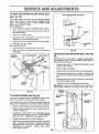
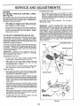
TO ADJUST
STEERING
WHEEL
TO START ENGINE WITH A WEAK BATTERY
ALIGNMENT
(See Fig. 26)
If steering wheel crossbars are not horizontal (left to right)
when wheels are positioned straight forward remove steering wheel and reassemble per instructions in the Assemb y
section of this manual°
FRONT
WHEEL
i
_
i _
! ,_
i _
TOE-IN/CAMBER
The front wheel toe-in and camber are not adjustable on
your tractor_ If damage has occurred to affect the front
wheel toe-in or camber, contact your nearest authorized
service center,,
TO REMOVE
WHEEL
If your battery is too weak to start the engine, it should be
recharged, ff "jumper cables" are used for emergency
starting, follow this procedure:
IMPORTANT:
YOUR UNIT IS EQUIPPED WITH A 12
VOLT NEGATIVE GROUNDED SYSTEM. THE OTHER
VEHICLE MUST ALSO BE A 12 VOLT NEGATIVE
GROUNDED SYSTEM_ DO NOT USE YOUR TRACTOR
BATTERY TO START OTHER VEHICLES.,
TO ATTACH JUMPER CABLES
o Connect each end of the RED cable to the POSITIVE
(+) terminal of each battery, taking care not to short
against chassis.
o Connect one end of the BLACK cable to the NEGATIVE (-) terminal of fully charged battery.
FOR REPAIRS
(See Fig. 25)
Block up axle securely
=
Remove axle cover, retaining ring and washers to alIow
wheel removal (rear wheel contains a square key - Do
not lose),
o
Repair tire and reassemble.
o
On rear wheels only: align grooves in rear wheel hub
and axle,, Insert square key.
o
Replace washers and snap retaining ring securely in
axle groove.
o
Replace axle cover°
CAUTION: Lead-acid batteries generateexplosivegases. Keepsparks, flame
and smoking materials away from batteries. Always wear eye protection
•
Connect the other end of the BLACK cable to a good
CHASSIS G ROUN D, away from fuel tank and battery.,
TO REMOVE CABLES, REVERSE ORDER •
•
WASHERS
BLACK cable first from chassis and fully charged
battery°
RED cable last from both batteries,
NEGATIVE TERMINAL
POSITIVE TERMINAL
RETAINING
RING
J
AXLE COVER
!
SQUAREKEY
(REARWHEELONLY)
FIG. 25
CABLES
CHARGED
BATTERY
POSITIVE TERMINAL
NEGATIVE TERMINAL
FIG, 26
21
MI=
.................
= ==
: .................I,=, 'l
,H= ii
SERVICE
i=.................
=,=======
,i
TO REPLACE
,,H,
= H,,,=
,,=.....
I
ADJUSTMENTS
, ===,=,
H==r=i=l,,,=,
==,,==lli=
,,,11=
TO REMOVE
FUSE (See Fig. 27)
Replace with 30 amp automotive-type plug-in fuse. The
fuse holder is located in the engine compartment, directly
in front of thedash.
,Hi
H,
HOOD AND GRILL
,
111
(See Fig. 28)
.
Raise hood.
,
Unsnap headlight wire connector_
•
Stand in front of tractor. Grasp hood at sides, tilt
forward and lift off of tractor,
=
To reinstall, slide hood pivot brackets into slots in
frame.
•
Reconnect headlight wire connector and close hood.
HOOD
<_
FUSE
HOLDER
(_
___
--.
FtGo 27
TO REPLACE
HEADLIGHT
o
Raise hood.
Pull bulb hotder out of the hole in the backside of the
grill°
o
Replace bulb in holder and push bulb holder securely
back into the hole in the backside of the grill,
Close hood.
FIG. 28
INTERLOCKS AND RELAYS
Loose or damaged wiring may cause your tractor' to run
poorly, stop running or prevent it from starting.
•
O% ,EOTOR
BULB
,,
•
HEADLIGHT
Check wiring. See electrical wiring diagram in Repair
Parts section of this manual°
22
m
t
, i , i,
,,11,,
i
.....
'
'
',
SERVICE AND ADJUSTMENTS
....
i, ,,1111,,
i iiii,,=111
....
i,, i,, i1,,,
ENGIINE
ACCELERATION
TO ADJUST THROTTLE
(See Fig. 2g)
•
CONTROL
CABLE
The throttle control has been preset at the factory and
adjustment should not be necessary_ Check adjustment as
described below before loosening cable. If adjustment is
necessary, proceed as follows:
High speed stop is factory adjusted.
damage may result.
With engine not running_, move throttle control lever
from "SLOW' to 'CHOKE position. Slowly move lever
from "CHOKE" to "FAST" position,
CARBURETOR
(See Fig. 29)
The carburetor has been preset at the factory and ad{ustment should not be necessary° However, minor adjustment may be required to compensate for differences in fuel,
temperature, altitude or load If the carburetor does need
adjustment, proceed as follows:
IDLE SPEED SCREW
In general, turning the mixture screws in (clockwise) decreases the supply of fuet to the engine giving a leaner fue!/
air mixture. Turning the mixture screws out (counterclockwise) increases the supply of fuel to the engine giving
a richer fuel/air mixture.
PLATE
THROTTLE CABLE
IMPORTANT:
DAMAGE TO THE NEEDLES AND THE
SEATS IN CARBURETOR MAY RESULT IF SCREWS
ARE TURNED IN TOO TIGHT.
PRELIMINARY
•
Do not adjust -
IMPORTANT:
NEVER TAMPER WITH THE ENGINE
GOVERNOR, WHICH IS FACTORY SET FOR PROPER
ENGINE SPEED. OVERSPEEDING THE ENGINE ABOVE
THE FACTORY HIGH SPEED SETTING
CAN BE
DANGEROUS° IF YOU THINK THE ENGINE-GOVERNED
HIGH SPEED NEEDS ADJUSTING, CONTACT YOUR
NEAREST AUTHORIZED SERVICE CENTER, WHICH HAS
PROPER EQUIPMENT AND EXPERIENCE TO MAKE ANY
NECESSARY ADJUSTMENTS.HIGH
SPEED NEEDS
ADJUSTING, CONTACT YOUR NEAREST AUTHORIZED
SERVICE CENTER, WHICH HAS PROPER EQUIPMENT
AND EXPERIENCE
TO MAKE ANY NECESSARY
ADJUSTMENTS.
Checkthat hole in throttle lever and hole in plate line up.
If holes A are not aligned, loosen clamp screw and
move throttle cable until holes are aligned. Tighten
clamp screw securely
TO ADJUST
TEST -
Move throttle control lever from "SLOW" to "FAST"
position. If engine hesitates or dies, turn high speed
mixture screwout (counterclockwise) 1/8turn. Repeat
test and continue to adjust, if necessary, until engine
accelerates smoothly,.
@
SETTING -
Be sure you have a clean air filter and the throttle
control cable is adjusted properly (see above).
CLAMP
SCREW
o
With engine off turn high speed mixture screw in
(clockwise) closing it finger tight and then turn out
(counterclockwise) +1-I/2 turns
•
Turn idle mixture screw in (clockwise) closing finger
tight and then turn out (countercloclwvise) t turn+
FINAL SETTING +
•
=
+
Start engine and allow to warm forfive minutes. Make
final adjustments with engine running and shift/motion
control lever in "NEUTRAL" position.
THROTTELEVER
FAST
With throttle control lever in "FAST" position, turn high
speed mixture screw in (clockwise_ until engine begins
todiethen turn out (counterclockwise) untilengine runs
rough. Turn screw to a point midway between those
two positions,
With throttle control lever in "SLOW" position, turn idle
mixture screw in (clockwise) until enginebeginstodie
and then turn out (counterclockwise) until engineruns
rough.. "]'urn screw to a point midway between those
two positions,
•
With throttle control lever in "SLOW" position, engine
should idle at 2100 RPM If engine idles too slow, turn
idle speed screw in (clockwise)
=
If engine idles too fast in "SLOW" position, turn idle
speed screw out (counterclockwise)
HIGH SPEED
MIXTURE SCREW
FIG. 29
23
.........
i,,i,,,i
.....................
illlll
!
,,
,,,,,
m
,.
,,u
i,i
,
__
,i,,
=l....
ill
ENGINE
Immediately prepare your tractor'for storage at the end of
the season or ifthe unit will not be used for30 days or more..
illl ill
illl u,,
FUEL SYSTEM
IMPORTANT:
IT IS IMPORTANT TO PREVENT GUM
DEPOSITS FROM FORMING IN ESSENTIAL
FUEL
SYSTEM PARTS SUCH AS CARBURETOR, FUEL FILTER,
FUEL HOSE, OR TANK DURING STORAGE.
ALSO,
EXPERIENCE INDICATES THAT ALCOHOL BLENDED
FUELS (CALLED GASOHOL OR USING ETHANOL OR
METHANOL) CAN ATTRACT MOISTURE WHICH LEADS
TO SEPARATION AND FORMATION OF ACIDS DURING
STORAGE.
ACIDIC GAS CAN DAMAGE THE FUEL
SYSTEM OF AN ENGINE WHILE IN STORAGE°
.
Drain the fuel tank.
i
CAUTION: Never store the tractor with
gasoline in the tank inside a building
where fumes may reach an open flame
or spark.
Allow the engine to cool
before storing in any enclosure.
............................
illl lU ii
TRACTOR
Remove mower' from tractor for winter storage. When
mower is to be stored for a period of time, clean it thoroughly, remove all dirt, grease, leaves, etc. Store in a
clean, dry area_
°
Start the engine and let it run until the fuel lines and
carburetor' are empty.
o
=
C leesapno_n_
_itt [ac ts°rc(SenoCLEA NI_
o
Never use engine or carburetor'cleaner products in the
fuel tank or permanent damage may occur.,
Use fresh fuel next season_
.
Inspect and replace belts, if necessary (See belt replacement instructions in the Service and Adjustments
section of this manual).
o
Lubricate as shown in the Customer' Responsibilities
section of this manual
o
Be sure that all nuts, bolts and screws are securely
fastened,. Inspect moving parts for damage, breakage
and wear. Replace if necessary.
o
Touch up_all rusted or' chipped paint surfaces; sand
lightly before painting.
"ai_theCustOmer
NOTE:
Fuel stabilizer is an acceptable alternative in
minimizing the formation of fuel gum deposits during storage. Add stabilizer to gasoline in fuel tank or storage
container'. Always follow the mix ratio found on stabilizer
container'. Run engine at least 10 minutes after adding
stabilizer to allow the stabilizer to reach the carburetor. Do
not drain the gas tank and carburetor ff using fuel stabilizer.
ENGINE
OIL
Drain oil (with engine warm) and replace with clean engine
oil. (See "ENGINE" in the Customer Responsibilities
section of this manual).
BATTERY
o
Fully charge the battery for storage,
CYLINDERS
o
After a period Of time in storage, battery may require
recharging.
•
Remove spark plug(s).
=
Pour one ounce of oil through spark plug hole(s) into
cylinder(s).
•
Turn ignition key to"START" position fora few seconds
to distribute oil
•
Replace with new spark plug(s).
•
To help prevent corrosion and power leakage during
long periods of storage, battery cables should be
disconnected and battery cleaned thoroughly (see"TO
CLEAN BATTERY AND TERMINALS" in the Customer Responsibilities section of this manual).
°
After cleaning, leave cables disconnected and place
cables where they cannot come in contact with battery
tei'rninals.
o
Be sure battery drain tube is securely attached°
OTHER
o
Do not store gasoline from one season to another.
o
Replace your gasoline can if your' carl starts to rust.
Rust and/or dirt in your gasoline will cause problems.
o
If possible, store your unff indoors and cover it to give
protection from dust and dirt
°
Cover your unit with a suitable protective cover that
does not retain moisture. Do not use plastic. Plastic
cannot breathe which allows condensation to form and
will cause your unit to rust,
IMPORTANT: NEVER COVER TRACTOR WHILE ENGINE
AND EXHAUST AREAS ARE STILL WARM,
24
i, u'ln'l'
i
i
....
TROUBLESHOOTUNG
CAUSE
ii
i,,,i,,,,,,,,i
,U,,l
CORRECTION
i,
Will not start
Hard to start
1.
Outoftuel
2
3
4.
5.
6.
7
Engine not "CHOKED"
Engine flooded.
Bad spark plug
Dirty air filter.
Dirty fuel filter.
Water in fuel.
properly
1.
Fi{i fuel tank.
2..
3.
4
5.
6.
7.
See "TO START ENGINE" in Operation section.
Wait several minutes before attempting to start
Replace spark plug
Clean/replace air filter.
Replace fuel filter.
Drain fuel tank and carburetor, refill tank with fresh
8.
9.
10
Loose or damaged wiring..
Carburetor out of adjustment.
Engine vatves out of adjustment.
8.
9..
10.
gasoline and replace fuel filter.
Check all wiring.
Contact a Sears Service CentedDepartmenl
Contact a Sears Service CentedDepartment
1
2.
3.
4..
5.
6.
7
8
Dirty air f{Iter
Bad spark plug.
Weak or dead battery
Dirty fuet filter.
Stale or dirty fuel.
Loose or damaged wiring.
Carburetor out of adjustment.
Engine va{ves out of adjustment.
t,
2.
&
4.
5.
6
7
8
CIean/replace air filter
Rep{ace spark plug
Recharge or replace battery
Replace fuel filter,,
Drain fuel tank and refill with fresh gasoline
Check all wiring
Contact a Sears Service CentedDepartment,
Contact a Sears Service CentedDepartment,
1o
2.
3.
4.
5_
6.
7.
B.
9.
Clutch'brake pedal not depressed..
Attachment ctulch is engaged
Weak or dead battery_
Blown fuse
Corroded battery terminals.
Loose or damaged wiring°
Faufty ignition switch
Faulty solenoid or starterr
Fauity operator presence switch(es).,
1.
2.
3.
4.
5.
6r
7.
8
9
Depress clutch/brake pedal.
Disengage attachment dutch.
Recharge or replace battery
Replace fuse.
Clean battery terminafs
Check atl wiring.
Check/replace ignition switch_
Check/replace solenoid or starter
Contact a Sears Service CentedDepartment
i
Engine will not turn over
i
i , illUl,U
n ,lUlUlU
Engine clicks but will not
start
t2
3.
41
Weak or dead battery.
Corroded battery terminals.
Loose or damaged wtrtng.
Faulty solenoid or starter.
1..
2.
3
4.
Recharge or repEace battery
Clean battery terminals.
Check all wiring
Check/replace solenoid or starter-
Loss of power
1o
2o
3.
4.
5
6
7
8
9.
Cutting too much grass/too fast.
Throttle in "CHOKE" position.
Build-up of grass, leaves and trash under mower_
Dirty air filter
Low oil FeveVdirty oil
Faulty spark plug.
Dirty fuel tilter
Stale or dirty fuel
Water in fuel
1
2.
3..
4
5
6
7
8_
9o
Set in "Higher Cut" position/reduce speed.
Adjust throttle control
Clean underside of mower housing
Clean!replace air filter.
Check otl level/change oil
Clean and regap or change spark plug
Replace fuel filter.
Drain fuef tank and reffli with fresh gasoline
Drain fuel tank and carburetor, refitl tank with fresh
10.
11.
12.
13.
14o
15.
Excessive vibration
Spark ptug wire toose_
Dirty engine air screen/fins.
Dirty/clogged muffler
Loose or damaged wiring..
Carburetor out of adjustment,
Engine valves out of adjustment..
1
2.
Worn, bent or loose btade.
Bent blade mandrel.
3.
Loose/damaged
10
11.
12
13o
14.
15
1.
2
3
part(s).
25
, i
POINTS
....................
PROBLEM
'
gasoline and replace fuel fiIter
Connect and tighten spark plug wire..
Clean engine air screen/fins.
Clean/replace muffler
Check all wiring
Contact a Sears Service CentertDepartment
Contact a Sears Service CentedDepartment
Replace bfade Tighten blade bolt.
Replace blade mand_'eL
Tightenloose
part(s) Repface damaged parts,
CORRECTION
,,=Nil
Engine continues to run
when operator leaves seat
with attachment clutch
1.
Checkwittng,
switches and connections,
ff not
corrected, contact a Sears Service Center/Department.
engaged
Poor CUt_uneven
Mower blades will not
rotate
Poor grass discharge
=r,_ i= ,
=11
Worn. bent or loose blade
Mower deck not level
1
2
Replace blade, Tighten blade bolt
Level mower deck.
3,
4,
Buildup of grass, leaves, and trash under mower
Bent blade mandre_
5_
Clogged mower deck vent holes from buildup of
grass, leaves, and trash around mandrels
3
4,
5,
Clean underside of mower housing.
Replace blade mandrel.
Clean around mandrels to open vent holes
1,
Obstruction
2.
3.
4,
We(n!damaged mower drive belt
Frozen idler paliey
Frozen blade mandrel
1,
2
3
4,
Remove
Reptace
Replace
Replace
t,
2,
3
4,
5
6
7
8,
9
10,
11_
in clutch mechanism
Engine speed too stow.
Travel speed too fast,
Wet grass
Mower deck not level
Low/uneven tire air pressure.
Worn, bent or loose blade
Buildup of grass, leaves and trash under mower,
Mower drive belt worn
Blades Improperly installed.
Improper blades used.
Clogged mower deck vent holes from buildup of
grass, Ieaves, and trash around mandrels,
1
2.
3.
4
5
6,
7
8
9
10.
11
obstruction
mower drive belt
idler pulley.
blade mandrel.
Place throttle control in "FAST" position.
Shift to slower speed.
Atlow grass to dry before mowing.
Level mower deck
Check tires for proper air pressure
Replace/sharpen blade Tighten blade bolt,
Crean underside of mower housing
Replace mower drive belt
Reinstall blades sharp edge down,
Replace with blades listed in this manual.
Clean around mandrels to open vent holes.
i
Headlight(s) not working
(if so equipped)
ii,
1o
2
1,
Switch is "OFF"
2.
3.
4,
5
Bulb(s) burned out,
Faulty light switch
Loose or damaged wiring
Blown fuse
1
2.
3
4.
5
Turn switch "ON"
Replace bulb(s).
Check/replace light switch.
Check wiring and connections,
Replace fuse,,
1.
2
Bad battery celt(e)
Poor cable connections.
1,
2
Replace battery
Check/clean all connections.
3,
4,
Faulty regulator (if so equipped).
Faulty alternator
3.
4,
Replace regulator_
Replace alternator
H,I=H '
Battery will not charge
26