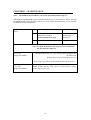
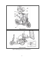
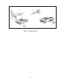
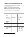
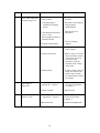
1
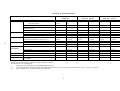
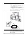
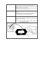
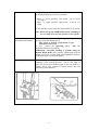
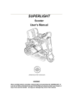
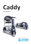
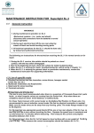
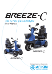
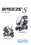
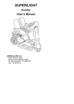
SPORTSTER SE
User’s Manual
AFI
KIM ELECTRIC VEHICLES
KIBBUTZ AFIKIM 15148, ISRAEL TEL: 972-4-6754814, FAX: 972-4-6751456
e-mail: [email protected]
websites: www.afiscooters.com
P/N PR00056
ac
WARNING
Read the User’s Manual carefully before operating the SPORTSTER. If you do not fully
understand any part of this Manual, please contact your dealer or any of our Service
Centers - as injury or damage may occur from misuse!
WARNING
Electromagnetic Interference (“EMI”) can cause powered vehicles to behave erratically,
which could be dangerous to the user. For your safety and protection, it is IMPERATIVE
that you take time to read Chapter 6 (“EMI WARNING”) before operating the
SPORTSTER.
Serial Number and Manufacturer’s data are fixed to the back side of the Headlight
Housing (subject to change as per local ordinances).
Date:
Edition:
Products:
April 2001
02
SE - Single Seat
SE – XXL Seat (65 cm)
SE – Wide Seat (79 cm)
c
CE CERTIFICATION
The Afikim Electric Vehicles Ref. Registration
Number with the Competent Authority (UK) is:
CA 000292.
Our Authorized Representative with the
Competent Authorities is:
MEDES LTD.
POB 231
Stanmore, Middlesex, HA7 4YA,
England
TEL/FAX: 0044-181-954-9964
c
CONTENTS
CHAPTER 1 - Overview Of The Sportster SE ......................1
Safety Instructions .................................................................2
General Description Of The Sportster SE..............................3
CHAPTER 2 - Adjustment & Operating Instructions.............6
CHAPTER 3 - Maintenance................................................12
CHAPTER 4 - Charging......................................................15
CHAPTER 5 - Troubleshooting and Fault Repair ...............17
CHAPTER 6 - EMI Warning................................................19
1
CHAPTER 1 - OVERVIEW OF THE SPORTSTER SE
Main features:
Congratulations on choosing the SPORTSTER as your electrically powered vehicle.
The SPORTSTER is easy to operate. The relatively large wheels enable driving on
unpaved roads, over rough terrain and to overcome obstacles as high as 4” (10 cm).
The SPORTSTER can climb slopes up to 21% - Single, 18% - Double. The braking
system stops the SPORTSTER smoothly and a short distance after the Operating
Lever is released.
A standard hand brake is also provided for backup. The Seat is spacious, comfortable
and can be rotated for easy access (standard Seats). All controls are conveniently
located and are simple to operate.
Under normal conditions the SPORTSTER can travel approximately 40 km (25 miles)
before the batteries require recharge.
The SPORTSTER SE is developed to use dry or gel batteries only.
The SPORTSTER SE Series includes Model SE -
- Single Seat
– XXL Seat (65 cm)
– Wide Seat (79 cm)
Please see Figure No. 1 for detailed specifications.
1
SAFETY INSTRUCTIONS
1.
Please note and strictly adhere to the following Safety Instructions. Additional
Warnings and Notices are printed in this User’s Manual; it is imperative that you
read carefully all chapters of this Manual before operating the SPORTSTER. It
is also advisable to refresh your memory by re-reading this Manual periodically.
Use gel/dry batteries only.
2.
Get acquainted with the SPORTSTER and its operational features before driving it.
3.
Drive slowly (Place Speed Selector in position 1) until you get used to the
SPORTSTER, to its various functions, safety features, and to its braking capabilities
and limitations.
4.
Watch carefully for pedestrians and drive your SPORTSTER accordingly. In
crowded areas always drive with the Speed Selector at Low Speed (position 1).
5.
Drive only where permitted according to all applicable local laws and ordinances.
6.
Never remove any of the SPORTSTER safety parts like Antitip, Device, Fenders,
or Emergency Brake lever
7.
DO NOT turn the Main Key Switch to “OFF” position while in motion; this may
cause abrupt and excessive deceleration which in turn may cause injury to the user
and damage to the SPORTSTER.
8.
Do not release the Manual Release Lever of the Electromagnetic Brake when the
SPORTSTER is on a slope.
9.
The load in the Rear Basket should not exceed 20 kg (44 lbs).
10.
The SPORTSTER is designed and built to carry ONE person only on the Single Seat
model, or two persons on the Double Seat model.
Never operate it with an additional person on board, not even a child.
11.
Do not change the Speed Selector position while driving.
12.
NEVER use the SPORTSTER for climbing up or riding down stairs.
13.
If for any reason the SPORTSTER does not stop when you release the Operating
Lever , immediately use the Hand Brake to stop the SPORTSTER and turn the Main
Key Switch to “OFF”.
Contact your dealer immediately.
14.
NEVER use a hose for cleaning. This may severely damage the power and electronic
components. Use only a damp cloth and mild detergent.
WARNING !!!
Special care must be taken to prevent children from operating the SPORTSTER.
2
GENERAL DESCRIPTION OF THE SPORTSTER SE
Note: 1. The numbers in parentheses refer to the parts illustrated on Figure 1.
Handlebars (2)
There are two separate and independently adjustable handlebars,
one of which houses the controls for the SPORTSTER. Your
SPORTSTER is delivered to you with right-hand controls. (Lefthands controls can be ordered through your dealer).
NOTE : On the Double Seat model the left handlebar is shorter
to allow for easier steering by the driver with 2 people
on board. For a single user two handlebars of the same
length can be supplied. Ask your dealer.
Headlight (3)
Charging Socket (4)
Seat (6)
The socket is used to connect the charger plug for batteries
charging.
The Single SPORTSTER Seat is equipped with folding armrests
(1) to allow convenient access to the Seat. The Seat itself can be
rotated. The upholstery may be removed for cleaning. (A deluxe
orthopedic adjustable Seat is also available. Ask your dealer).
The Double SPORTSTER Seat is equipped with folding armrests
(1) as in the Single Seat model and can be tilted to make service
more accessible. It can also be supplied with a Canopy (10) for
protection from rain and sun.
Fuses (5)
5A - Main Fuses 2x40A – Semi Automatic
5B - Light Fuse (3A) 6x32 option - Semi Automatic
5C - Charging Fuse 15A – Semi Automatic
Seat Rotation Lever (7)
The Lever is used to swivel the Seat 45 degrees in either
direction, to ease the driver's access to the Seat.
Rear Basket (8)
(Optional for Single Seat
model and standard for
Double Seat model)
Serial No.
For carrying parcels and personal effects. Maximum load 20 kg
(44 lbs).
Manual Release Lever of
Electromagnetic Brake
(11)
Located under the seat at the rear right of the SPORTSTER, the
Electromagnetic Brake Manual Release Lever allows free
movement of the SPORTSTER. To release, simply push the
brake lever forward. To engage brake, pull lever backward.
When lever is released the vehicle can not be operated.
Serial Number and Manufacturer’s data are located on the rear
side of the main lamp, and of the back of rear tray.
3
Single Seat Model
Figure 1
4
TECHNICAL SPECIFICATIONS
MODEL No. :
Dimensions *
Weights *
Speed **
5
Climbing ability
Tires
(pneumatic)
Towing
Batteries ***
Travel distance
Units
Length (without rear basket)
(with rear basket)
Width
Height (for transport: handles, seat and front
wheel removed)
Ground clearance
Total, without batteries
Total, with batteries
Maximum load (including rear basket load)
Forward (Speed selector position No. 2)
Forward (Speed selector position No. 1)
Reverse
Maximum slope (100 kg- 220 lbs load)
Obstacles
Front tire size
Rear tires size
Pressure
Level surface, driver 75 kg (165 lbs)
Gel/dry batteries only
Fully charged batteries, level surface, driver 75
kg ( 165 lbs)
SE
Single Seat
Metric
USA
150 cm
59”
175 cm
69”
72 cm
28”
77 cm
30.5”
SE
XXL Seat (65 cm)
Metric
USA
170 cm
67”
SE
Wide Seat (79 cm)
Metric
USA
170 cm
67”
76 cm
77 cm
30”
30.5”
90 cm
77 cm
35”
30.5”
12 cm
75 kg
115-125 kg
200 kg
10 km/h
6 km/h
6 km/h
21%
12 cm
12 cm
90 kg
130-140 kg
200 kg
10 km/h
6 km/h
6 km/h
18%
12 cm
5”
198 lbs
287-309 lbs
440 lbs
6.2 mp/h
3.7 mp/h
3.7 mp/h
12 cm
90 kg
130-140 kg
200 kg
10 km/h
6 km/h
6 km/h
18%
12 cm
5”
198 lbs
287-309 lbs
440 lbs
6.2 mp/h
3.1 mp/h
3.1 mp/h
5”
165 lbs
254-276 lbs
440 lbs
6.2 mp/h
3.7 mp/h
3.7 mp/h
5”
10x2.75”
14x2.75”
20-25 psi
220 lbs
2x12 V
25.0 miles
100 kg
60-70 Ah
40-45 km
100 kg
60-70 Ah
40-45 km
5”
10x2.75”
14x2.75”
20-25 psi
220 lbs
2x12 V
25.0 miles
All technical specifications are subject to change without prior notice.
All dimensions are in round figures.
*
Dimensions and weight do not include SPORTSTER Canopy.
**
The maximum speed can be adjusted by the manufacturer to allow for lower or higher maximum speed (i.e., max. 15 km/h - 9.3 mp/h).
***
Deep cycle batteries. Consult your dealer for other sizes.
5
100 kg
60-70 Ah
40-45 km
5”
10x2.75”
14x2.75”
20-25 psi
220 lbs
2x12 V
33.5 miles
CHAPTER 2 - ADJUSTMENT & OPERATING INSTRUCTIONS
(Reference numbers refer to the figures at the bottom of each page)
Adjusting the Handlebars
Adjust angles and height of both handlebars as follows:
• Release the Handlebars Clamp (1), which secures the
handlebars in place, by turning the cam Lever outward from
the vehicle.
• Adjust the height and angle of your handlebars, by turning,
while raising or lowering the handlebars.
• Tighten handlebars at the desired height and direction: secure
the Handlebars Clamp (1) by turning cam Lever inward.
Adjusting the Hand
Brake
The hand brake cable mechanism can be adjusted by any
authorized serviceman, dealer or by any professional authorized
to adjust hand brakes mounted on bicycles or motorcycles.
The Hand Brake is part of your safety system. DO NOT
adjust the Hand Brake by yourself - get professional
assistance!
Seating into the
SPORTSTER
Before driving the SPORTSTER make sure that the Charging
Plug is disconnected from the Charging Socket (3).
Note: While the Charging Plug is inserted in the Charging
Socket, the unit cannot be operated.
Lift the Lever (4) upward, rotate the Seat (5) and raise the
Armrest (2) to give you easy access to the Seat.
6
Key Switch
• The SPORTSTER has a Main Key Switch (9) - located on the
right side of the Headlight Housing.
The Main Key Switch has two positions:
• “OFF” - The SPORTSTER cannot be driven and the
Electromagnetic Brake is locked.
• “ON” - Power is supplied to the SPORTSTER. The
Electromagnetic Brake releases automatically when the
Operating Lever is squeezed.
To operate the SPORTSTER, insert the key into the Main Key
Switch and turn it to “ON” (clockwise). The switch will remain
in this position and the green (2) light will be lit.
Automatic Shut Off
When Key Switch is at “ON” position, after a few minutes (about
20 minutes) without using the Operating Lever, the control
system will be shut off automatically to save battery energy.
In such cases, to restart control system, turn Main Key Switch
“OFF” and “ON” again.
7
Battery Status Indicator
The Battery Status Indicator (1) located on top of the Headlight
Housing shows you the remaining capacity of the batteries.
When the indicator shows that mid-half capacity remains,
recharge batteries as soon as possible.
When the indicator points that to firs or second segment on the
left there are only about 5 km (3 miles) to go.
Fault Indicator
When the green light of the Fault indicator (2) is lit, the vehicle is
“ready”.
When the Fault Indicator (2) is Green/Red Flashing the Vehicle
is in Fault condition or the brake manual lever is released.
(The Flashing Code can be Decoded by technician).
Forward/Reverse Selector
The Forward/Reverse Selector (14) is located on the handlebar.
Select the desired direction (as marked). In reverse mode, a
warning buzzer sounds automatically (in certain models only and
subject to local ordinances).
Warning: Do not change Selector position while the
SPORTSTER is in motion.
8
Speed Range Selector
The Speed Range Selector (16) is located on the left side of
the Headlight Housing. It has two positions:
• Mark “1” (lower position): Low speed - up to 6 km/h
(3.1 mph).
• Mark “2” (upper position): High speed - 10 km/h (6.2
mph).
Do not shift the selector while the SPORTSTER is in motion.
Note: When driving the SPORTSTER inside a building or
in a crowded area, use only position 1 (Low speed).
Operating Lever (red)
and Manual Hand Brake
To start driving, squeeze the Operating Lever (18) gently
until you reach the desired speed.
The speed is directly proportional to the
deflection of this Lever .
To stop - release the Operating Lever
(18). The
SPORTSTER will stop gradually.
Additionally, emergency braking is possible using the
Manual Hand Brake (17). Squeeze Hand Brake and use
Button (21) to lock it (USE THIS FOR PARKING). Squeeze
Hand Brake again to release the button.
Signaling
Before turning, shift the “Turn Signal Switch” (19), on the
Handlebar to the desired direction - left for left, right for
right. This will activate blinking lights on the rear fenders. A
warning buzzer also sounds (in certain models only and
subject to local ordinances).
9
Horn/Buzzer (in certain
models only)
Push Button (20) activates a buzzer.
The buzzer sounds automatically under the following
conditions (subject to change where prohibited by law):
1. When reversing.
2. When operating the “Turn Signal Switch” (Right or Left).
3. When the “Emergency Electromagnetic Brake Lever ” is
operated.
Headlight Switch
Turn on the Headlight (24) with Light Switch (23). This
switch activates both the Headlight and the Rear Lights (28).
Hazard Warning
The Hazard Button (20) operates all flashing lights on the
SPORTSTER. Pushing the button once turns the lights ON.
A second push turns them OFF.
10
Parking
After stopping, turn the Main Key Switch to OFF and remove the
key. The lights will turn OFF. The Electromagnetic Brake is
engaged (locked).
Note: The Electromagnetic Brake is automatically locked
whenever the Operating Lever is released and after
the SPORTSTER stops completely.
The Hand Brake Lever (26) can be locked by pushing Button
(27) while squeezing Hand Brake Lever . To release the Hand
Brake - squeeze Lever (26) gently.
11
CHAPTER 3 - MAINTENANCE
Note: The numbers in parentheses refer to the parts illustrated in figure 2.
Although the SPORTSTER requires minimal maintenance, do not neglect it. When servicing
the SPORTSTER, make sure that it stands on a level surface and that the key is not inserted.
In addition, lock the Hand Brake.
Periodic Maintenance
Check
No.
Type of Service
Frequency
1
Check water level in the batteries.
Add water as needed.
(Lead acid batteries only)
Bimonthly or as per
manufacturer’s
instructions
2
Check air pressure in all tires.
Every two weeks
Note: To check the batteries, the Gray Cover located under
the Seat must be removed.
Removing the Gray
Cover (33)
(Single Seat Model)
Remove the Seat (29): hold the backrest at marked position with
one hand and press Lever (30) with the other, lifting the seat
up off its pivot
Release Gray Cover 4 securing screws (31).
Lift the Gray Cover until it is released from the Seat Pivot (32).
Replacing the Gray
Cover (33)
(Single Seat Model)
The replacement of the Gray Cover is done in reverse order;
MAKE SURE that the Gray Cover (33) fits onto it’s place.
Secure with 4 screws (31).
12
Single Seat Model
Double Seat Model
Figure 2. Removing the Gray Cover for Maintenance
13
Removing the Gray
Cover (33)
(Double Seat Model)
Release the lock spring (37) under the Seat and tilt Seat (36) back
about 70 degrees until it is almost standing on the rear part of the
frame.
Remove the Gray Cover (33) as described above (for Single Seat
Model).
Replacing the Gray
Cover (33)
(Double Seat Model)
Replacement of the Gray Cover is done in reverse order.
Tilt Seat back and mount on Seat Shaft.
Batteries
Every two months, check the water level in both batteries.
Note: Failure to maintain water level in the batteries will
cause damage and void the manufacturer’s warranty.
Checking Water Level
Remove the Gray Cover. Open the strap holding the batteries in
place and check the water level in each of the battery cells.
Normal water level is approximately 6 mm (1/4”) above the
plates. If the water level is lower, add distilled water.
Note: use ONLY distilled water.
Tires
Correct air pressure in the tires is essential for optimal steering
and stability of the SPORTSTER. Check air pressure every two
weeks. Inflate to the proper air pressure (20 – 25 psi).
Solid tires (optional) should be checked visually and replaced if
excessive wear or damage is noticed.
14
CHAPTER 4 - CHARGING
Read Charger’s manual before using the charger..
Warning: If you use a different charger, ask your dealer for instructions.
CHARGING BATTERIES
(See figure 3)
1. Insert the Charging Plug into the Charging Socket located on the front of the GRAY
COVER, at the center.
2. Plug the power cord of the charger into a wall outlet.
3. When charging is completed and you are ready to go - unplug the charger from the
wall outlet and remove the charger plug from the SPORTSTER.
4. In ideal storage conditions, batteries which were charged to full capacity and were
not used should be recharged every 6 months.
5. If you are planning not to use your SPORTSTER for an extended period of time, we
recommend charging it for two days and then disconnecting the batteries.
6. If you have not used your SPORTSTER for an extended period of time, charge the
batteries for at least 24 hours before driving.
• Note: There is NO need to disconnect the Charging Plug promptly after the
charging is complete.
• However, DO NOT leave the Charger connected to the batteries FOR MORE
THAN TWO WEEKS.
• As long as the Charging Plug is in the Charger Socket, the electronic control of
the SPORTSTER automatically cuts all power to the motor and the
SPORTSTER cannot be driven.
15
Figure 3. Charging batteries
16
CHAPTER 5 - TROUBLESHOOTING AND FAULT REPAIR
The following table provides troubleshooting and repair instructions for symptoms
encountered when operating the SPORTSTER. It presents the best ways to handle
the faults. The table contains three columns:
The Symptom - describes the functional problem that results from the fault.
Probable Cause - lists all probable causes for the relevant symptom. The probable
causes are listed logically by order of probability: the first one is the most probable.
Remedy - lists the action to be taken to solve the problem. The appropriate remedy
appears opposite each probable cause. These remedies should solve the problem; if
not, continue down the list to the next cause/remedy.
Remember: you may contact your dealer at any time for further professional support.
No.
1
2
Symptom
Flat tire and unstable
driving.
The Service LED
Flashed and the
vehicle does not move.
Probable Causes
Remedy
• Low air pressure.
◊ Pump to normal pressure.
• Puncture.
◊ Repair the punctured tire.
• Manual Release Lever
pushed forward.
◊ Pull Lever Backwards.
• Controller Coded Fault.
◊ Ask for technical
assistance.
3
The Service LED
Flashed and the
vehicle moves only at
low speed.
• Electric column is at up.
◊ Lower column position.
4
Manual Mechanical
Brake Lever is fully
pressed but the
vehicle does not stop.
• Loose hand brake
mechanism.
◊ Tighten the brake cable.
5
The Key Switch is • Main fuse popped out.
turned
to
“ON”
(clockwise), but the
“ON” light does not
come on.
TROUBLESHOOTING AND FAULT REPAIR (Cont.)
17
◊ Reset fuse.
Note: Do not reset fuse
more than twice. If
the symptom recurs
after resetting the
second time, call
the
authorized
dealer for further
technical support.
No.
Symptom
6
SPORTSTER does not
move when squeezing
the Operating Lever .
Probable Causes
• Main Key Switch is in
OFF position.
• Charging Plug is
installed in Charging
Socket.
• The Mechanical Release
Lever of the
Electromagnetic Brake is
pushed Forward.
• Control system failure.
7
8
9
Intermittent drive.
RIGHT or LEFT turn
signal light is
inoperative.
Headlight and/or rear
light are not lit.
Remedy
◊ Turn the key to “ON”
position.
◊ Disconnect the Charging
Plug from the
SPORTSTER.
◊ Pull out the Lever
Backward
◊ Call for technical
support.
• Battery capacity low.
◊ Charge batteries for at
least 18 hours.
• Failed connections
◊ Remove Gray Cover and
check the battery cables
connection. In case of
corrosion of the
terminals, clean the
terminals with a damp
clean cloth.
• Faulty battery.
◊ If, after recharge, the red
lamps are still ON, the
battery may be faulty.
For replacement, contact
your dealer.
• Blown light fuse or
popped out - Figure 1.
◊ Replace light fuse or
reset fuse if automatic see Figure 1.
• Burnt out bulb.
◊ Replace bulb.
• Blown light fuse or
popped out - Figure 1.
◊ Replace light fuse or
reset fuse if automatic see Figure 1.
• Burnt out bulb.
◊ Replace Headlight bulb.
18
CHAPTER 6 - EMI WARNING
All types of electrically powered vehicles, such as powered wheelchairs and
motorized scooters (in this text all types will be referred to as “powered
vehicles”) may be susceptible to electromagnetic interference (EMI). This is
interfering electromagnetic energy (EM) emitted from sources such as radio
and TV stations, amateur radio (HAM) transmitters, two-way radios and
cellular phones. The interference (from radio wave sources) can cause the
powered vehicle to release its brakes, move by itself, or move in unintended
direction. It can also damage the powered vehicle’s control system. The
intensity of the interfering EM energy can be measured in volts per meter
(V/m). Each powered vehicle can resist EMI up to a certain intensity. This is
called its “immunity level”. The higher the immunity level, the greater the
protection. At this time, current technology is capable of achieving immunity
level, which would provide useful protection from the more common sources of
radiated EMI. This vehicle as shipped, with no further modification, has an
immunity level of 10 V/m.
There are a number of sources of relatively intense electromagnetic fields in
everyday environment. Some of these sources are obvious and easy to avoid.
Others are not apparent and exposure is unavoidable. However, we believe that
by following the warning listed below, your risk of EMI will be minimized.
The sources of radiated EMI can be broadly classified into three types:
1)
Hand-held portable transceivers (transmitters-receivers) with the
antenna mounted directly on the transmitting unit. Examples include:
citizen band (CB) radios, “walkie talkies”, security, fire and police
transceivers, cellular telephones and other personal communication
devices. ** NOTE: some cellular telephones and similar devices
transmit signals while they are ON, even when not being used.
2)
Medium-range mobile transceivers (Such as those used in police
cars, fire trucks, ambulances and taxis.) These usually have the
antenna mounted on the outside of the vehicle, and -
3)
Long-range transmitters and transceivers such as commercial
broadcast transmitters (Radio and TV broadcast antenna towers)
and amateur (HAM) radios.
NOTE: Other types of hand held devices, such as cordless phones, laptop
computers, AM/FM radios, TV sets, CD players, cassette players and
small appliances such as electric shavers and hair dryers, as far as we
know, are not likely to cause EMI problems to your powered
vehicle.
Powered Vehicle Electromagnetic Interference (EMI)
Because EM energy rapidly becomes more intense as one moves closer to the
transmitting antenna, the EM field from hand-held radio wave sources
(transceivers) are of special concern. It is possible to unintentionally bring high
levels of EM energy close to the powered vehicle’s control system while using
these devices. This can affect powered vehicle movement and braking.
Therefore, the warnings listed below are recommended to prevent possible
interference with the control system of the powered vehicle.
19
WARNINGS
Electromagnetic interference (EMI) from sources such as radio and TV
stations, amateur radio (HAM) transmitters, two-way radios and cellular
phones can affect powered vehicles.
Following the warnings listed below should reduce the chance of unintended
brake release or powered vehicle movement which could result in serious
injury:
1)
Do not operate hand-held transceivers (transmitters-receivers) such as
citizen band (CB) radios, or turn ON personal communication devices
such as cellular phones, while the powered vehicle is ON;
2)
Be aware of nearby transmitters, such as radio or TV stations and try
to avoid coming close to them
3)
On appearance of unintended movements or brake release
occurrences, switch the powered vehicle OFF as soon as it is safe.
4)
Be aware that adding accessories or components, or modifying the
powered vehicle, may make it more susceptible to EMI (Note: there
is no easy way to evaluate their effect on the overall immunity level
of the powered vehicle), and -
5)
Please report to us all incidents of unintended movement or brake
release and note whether there is a source of EMI nearby.
Important information
1)
10 volts per meter (V/m) is a generally achievable and useful immunity
level against EMI (as of May 1994). The higher the level the greater the
protection;
2) This product as delivered to you has an immunity level of 10 V/m.
20
Distributed by
AFIKIM ELECTRIC VEHICLES
KIBBUTZ AFIKIM, 15148, ISRAEL,
Telephones
Main Office:
Sales Department:
972 4 6754814
972 4 6754180
Fax
972 4 6751456
E - Mail
[email protected]
Websites
www.afiscooters.com