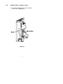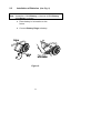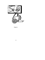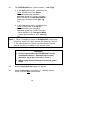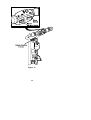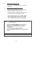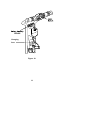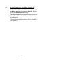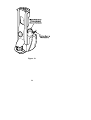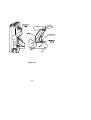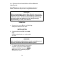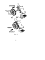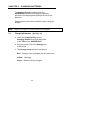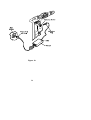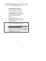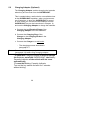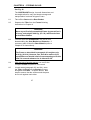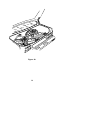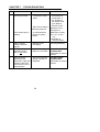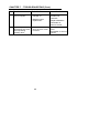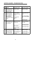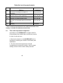
1
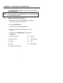
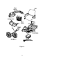
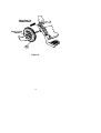
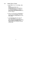
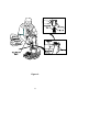
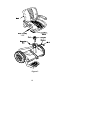
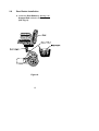
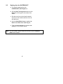
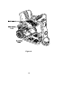
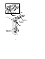
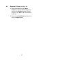
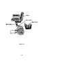
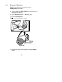
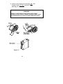
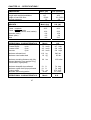
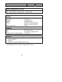
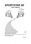
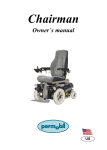
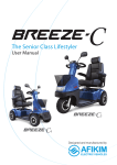
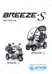
SUPERLIGHT
Scooter
User’s Manual
WHEELCARE, Inc.
12691 Monarch Street
Garden Grove California 92841
Tel 800-448-5999 , 714-230-6132
Fax 714-230-6154
WARNING
Read carefully before assembly, disassembly and operating the
SUPERLIGHT. If you do not fully understand any part of this
Manual, please contact your dealer or any of our service centers as injury or damage may occur from misuse.
WARNING
Electromagnetic Interference (“EMI”) can cause powered vehicles
to behave erratically, which could be dangerous to the user. For
your safety and protection, it is IMPERATIVE that you take time to
read Chapter 11 (“EMI WARNING”) before operating SUPERLIGHT
or any other powered vehicle.
If further clarification is required, please contact your dealer or
any of our service centers: see the back cover of this User’s
Manual.
The SUPERLIGHT passed the EMI testing: See Chapter 11.
Serial Number Label is affixed to the Tiller: See Fig 10.
CONTENTS
Page
Subject
CHAPTER 1 - DELIVERY and UNPACKING ..................................... 1
CHAPTER 2 - ASSEMBLY................................................................ 3
CHAPTER 3 - OPERATING INSTRUCTIONS ................................ 17
CHAPTER 4 - DISASSEMBLY......................................................... 25
CHAPTER 5 - THE CHARGER........................................................ 33
CHAPTER 6 - STORING IN CAR ..................................................... 37
CHAPTER 7 - TROUBLESHOOTING.............................................. 39
CHAPTER 8 - SAFETY INSTRUCTIONS....................................... 42
CHAPTER 9 - SERVICE .................................................................. 44
CHAPTER 10 - SPECIFICATIONS.................................................. 47
CHAPTER 11 - EMI WARNING ....................................................... 49
A
CHAPTER 1 - DELIVERY and UNPACKING
The SUPERLIGHT Scooter is delivered to you packed in 2
Cardboard Boxes. .
Note: The boxes weights 30+28kg (66+62 lb.) - do NOT attempt
to lift it without assistance.
1.1
Unpack as follows (See Fig. 1)
a. Place boxes on floor with side up as marked by
the arrows on the side of the box.
b. Cut the Plastic Bands.
c. Remove the cardboard Top Cover.
d. Remove all parts from the boxes (and lay on
the floor)
e. Identifying the SUPERLIGHT Components
(See Fig. 1)
(1) Batteries Cover
(6)
Charger
(2) Rear Wheels
(7)
Seat Adapter
(3) Frame
(8)
Tiller
(4) Seat
(9)
Rear Basket
(5) Batteries (left & right)
1
Figure 1.
2
CHAPTER 2 - ASSEMBLY
2.1
Installation of Rear Wheels (See Fig. 2)
a. Squeeze the center Pin in the Hub
Cap.
Push the wheel back on, to the end of
the axle.
WARNING
After installing the wheel please check carefully that it is
properly positioned and secured back in place.
b. To assure that the wheel is secured in
its place, try to pull it off axle without
touching the Pins. The wheel should
NOT come off. If necessary repeat
procedure a. above.
3
Figure 2.
4
2.2
Joining Tiller to Frame.
a. Place Tiller in front of the Frame. (See
Fig. 3).
Kneel at the left side of the
SUPERLIGHT holding the left side of
the Top Handle Bars of the Tiller with
your left hand. The Tiller should be
vertical and slightly inclined backward as
shown in Fig. 3.
b. With your right hand lift the Housing (at
the front end of the Frame) and place it
above the (black) Tapered Pin mounted
on the Tiller.
c. Let the Housing slide down onto the
black Tapered Pin until you hear a
“click”: at this time the Retaining Spring
should engage the Groove on the
Tapered Pin thus locking both sections
to each other.
5
Figure 3.
6
2.2
Joining Tiller to Frame. (Cont.)
d. Connect the Electric Plug to the Socket
in the Tiller (See Fig. 4).
Figure 4.
7
2.3
Installation of Batteries (See Fig. 5)
Note: Installation of L.H Battery is identical to R.H. Battery.
L.H. Battery is shown.
a. Place battery in its location on the
frame.
b. Connect Battery Plugs to battery.
Figure 5.
8
2.4
Installation of Batteries Cover (See Fig. 6)
a. Place Batteries Cover over the Batteries
b. Push back Plastic Clip to secure the Batteries
Cover in its location.
9
Figure 6.
10
2.5
Seat Installation (Figure 7)
Seat Installation and Adjust:
a. Insert the Seat Adapter into the SeatBushing.
(1)
Verify that the Seat-Bushing
slot is in forward direction.
(2)
Install bolt and washer and
tighten the bolts very well,
using the attached wrench.
(3)
Install and tighten the
securing nut very well, using
the attached wrench.
(4)
Install the Seat into the SeatBushing while the Seat is
45 degree to the side of the
frame.
(5)
Press the Seat Turning
Lever to place the Seat
forward position.
b. Adjusting the height of the Seat.
Remove nut, bolt and washer. Change
the Seat Adapter height, install, bolt
and washer and tighten strongly
tightened and tighten the securing nut
very well.
c. Install Seat Upholstery.
11
Figure 7.
12
2.6
Rear Basket Installation
a. Install the Rear Basket by placing it on
Support Rod welded to the rear frame.
(See Fig. 8).
Figure 8.
13
2.4
After the assembly make sure that: a. All parts are undamaged, properly
assembled and secured.
b. All electrical plugs are properly fastened.
c. The operating levers return
automatically to center position when
they are squeezed and released.
It is recommended to charge the batteries overnight
before operating the SUPERLIGHT for the first time.
See Chapter 5 for charging instructions.
14
2.5
Seating into the SUPERLIGHT
a. For comfort entering into the
SUPERLIGHT (See Figure 9).
b. Lift the Seat Turning Lever and turn the
Seat 45 or 90 degree to the side of the
frame.
c. Sit down and turn swivel back towards
the front of the vehicle while the lever is
still pulled up.
d. Use the Seat Slider Lever to adjust the
Seat forward/Backward (See Fig. 9).
e. Fold the Seat Armrest as desired while
getting in or out of the vehicle.
Note: For your safety, always keep the armrest closed: Forward –
Down while seated.
15
Figure 9.
16
CHAPTER 3 - OPERATING INSTRUCTIONS
PLEASE READ THOROUGHLY CHAPTER 8 - “SAFETY
INSTRUCTIONS” - BEFORE DRIVING THE SUPERLIGHT.
3.1
Mount the SUPERLIGHT, insert the Key into the Slot
and turn it clockwise to the (marked) ON position. The
Key will remain in this position. Panel On Light should
come ON. (See Fig. 10).
3.2
You can drive forward by gently squeezing the Right
Hand Operating Lever. You can drive reverse by
gently squeezing the Left Hand Operating Lever.
− The speed of the SUPERLIGHT
is proportional to the deflection
of the Levers; the more you
squeeze the faster you go
(either direction).
3.3
TO STOP : Release the Lever - it returns
automatically to its center (neutral) position and the
SUPERLIGHT stops.
Note: For your safety and comfort the following features are part of
the normal operating sequence;
-
Slight delay after you squeeze the Lever before
the motor is engaged-
-
When squeezing or releasing the Lever you
should hear a “click” indicating that the
Electromagnetic Brake is activated.
17
Figure 10.
18
3.4
The SUPERLIGHT has 2 speed modes ; Low / High
a. In the High speed mode (marked by the
“hare” symbol next to the Speed
Selector switch) the maximum
attainable speed is 7.5 km/h (4.6 mph)
When selector is in High Speed Mode –
Green light of switch is ON. (See Fig.
11).
b. In the Low speed mode (marked by the
“turtle” symbol next to the Speed
Selector switch ) the maximum
attainable speed is 4.5 km/h (2.8 mph).*
* When selector is in Low Speed Mode
– Green light of switch is OFF. (See Fig.
11).
Notes: 1. There is available a model of SUPERLIGHT in which the
maximum speed is 6.0 km/h and the low speed is 3.0 km/h.
2. The manufacturer to client’s requirement can limit the
speeds. Contact your dealer or our service center
WARNING
1. Until you get used to the SUPERLIGHT and its
operational features - Speed Selector switch
should be set at the Low mode (“Turtle”).
2. When going down hill always use the low speed
mode.
3.5
Set the Speed Selector switch as desired.
3.6
When “extra-power” is needed (i.e., climbing allowed
slopes) use the High speed mode.
19
Figure 11.
20
3.7
Lights Operating (See Fig. 12)
To switch on the SUPERLIGHT light, use the RightBlue switch . .
3.8
Battery Capacity Indicator (See Fig. 12)
The Battery Capacity Indicator is part of the Disply
Panel. The indicator contains 4 left leds .
The battery capacity is proportional to the numbers of
the illuminated leds. (Not include the ON led).
Thus 4 Illuminated leds means: 75%-100% capacity.
Thus 3 Illuminated leds means: 50%-75% capacity
Thus 2 Illuminated leds means: 25%-50% capacity
Thus 1 Illuminated leds means: 0%-25% capacity
Notes: 1. The Battery Capacity Indicator reset itself to full (4 leds)
only after full recharge.
2. In case that Charging Adapter is used to charge the
Batteries out of the SUPERLIGHT, the Battery
Capacity Indicator of the vehicle will not reset
automatically
To reset the Battery Capacity Indicator
Turn on the key switch and wait for 2 minutes without
driving
Note: We recommend charging the batteries at the end of each day.
21
Charging
fuse
Figure 12.
22
3.9
In case of power fail, low battery or other fail
The SUPERLIGHT can be pushed manually by turning
the Motor Cap Knob in clockwise (See Fig. 13) and
pushing the SUPERLIGHT by hand.
The SUPERLIGHT will not operate and the buzzer will
beep until the Motor Cap Knob is turned back to its
original position.
(The buzzer will operate only when the key switch is in
“ON” position).
23
Figure 13.
24
CHAPTER 4 - DISASSEMBLY
4.1
Separation of Tiller from Frame (See Fig. 14).
For ease of operation we recommend working on the
left side of the SUPERLIGHT (facing forward ):
a. Disengage the Electric Plug from its
socket in the Tiller by squeezing the
Snap Button (located on the plug) - and
pull.
b. Support the Tiller with your left hand
holding the Upper Left Rail.
c. Push the Retaining Spring with the
thumb of the right hand until it is freed
from the Groove on the (black) Tapered
Pin.
d. Carefully lift the Frame off the Tapered
Pin and lay both sections on the floor.
25
Figure 14.
26
4.2
Removal of Seat (See Fig. 15)
a. Remove the Seat from the Seat
Adapter by lifting the Seat straight up
while turning Release Lever is pulled
only when the Seat is 45ºback direction
to the left.
b. Remove the Rear Basket by lifting it up
from its Support Rod.
27
Figure 15.
28
4.3
Removal of Batteries
Batteries can be easily removed from your
SUPERLIGHT as follows a. Remove Seat and Rear Basket (see instructions in
paragraph 4.2 above).
b. Open Batteries Cover - (See Fig. 16).
1) Pull back Plastic Clip
2) Tilt and lift up Cover as shown
Figure 16.
c. Disconnect cables from batteries: unplug Battery
Plugs.
29
d. Remove each battery BY PULLING UP THE
HANDLE AND LIFTING THE BATTERY
(See Fig. 17).
WARNING
Failure to follow above instructions could cause
pinching of your hand or fingers if battery slides down
and causes hand to come in contact with other parts.
Main Fuse
On battery
Figure 17.
30
4.4
Removal and Installation of Rear Wheel/s
(See Fig. 18)
Rear Wheel/s can be removed to facilitate storage at
home, in the trunk of your car or for general service.
WARNING
Before attempting to remove Rear Wheel/s, you need to
support the SUPERLIGHT by inserting any support block
under the Frame. The block should be large and strong
enough to allow the wheel/s to clear the ground by
approximately 3-4 cm (1.2-1.6 inch).
REMOVAL
a. Squeeze the center Pin in the Hub Cap
and pull the wheel off the axle.
INSTALLATION
b. Squeeze the center Pin in the Hub
Cap.
Push the wheel back on, to the end of
the axle.
WARNING
After installing the wheel please check carefully that it is
properly positioned and secured back in place.
c. To assure that the wheel is secured in
its place, try to pull it off axle without
touching the Pins. The wheel should
NOT come off. If necessary repeat
procedure b. above.
31
Figure 18.
32
CHAPTER 5 - CHARGING BATTERIES
The Battery Charger supplied with your
SUPERLIGHT controls the charging operation,
prevents over-charging and prolongs the life of the
batteries.
Read chargers instructions carefully before using the
charger.
Note: There is no ON/OFF power switch to the charger.
5.1
Charging Batteries (See Fig. 19)
a. Insert the Charging Plug into the
Charging Socket in the right hand side
of the Tiller of the SUPERLIGHT.
b. Plug the power cord of the Charger into
a wall outlet.
c. The Charger Lamp will show as follows:
Red – Charger Cord is plugged into the wall outlet.
Yellow – Charging
Green – Battery are fully charged .
33
Figure 19.
34
When charging is complete and you are ready to go - unplug
the Charger from the wall outlet and then pull out the charging
plug from the charging socket.
d. Under ideal storage conditions,
batteries which were charged to full
capacity and not used - will remain
charged for approximately 6 months.
e. If you are planning not to use your
SUPERLIGHT for an extended period of
time, we recommend charging it for two
days and then disconnecting the
batteries.
f.
If you have not used your
SUPERLIGHT for an extended period of
time, charge the batteries for at least 12
hours before driving.
Notes: • There is NO need to disconnect the Charging Plug
promptly after the charging is complete.
• HOWEVER, do not leave the Charger connected to
the batteries for more than two weeks.
• As long as the Charging Plug is in the Charging
Socket, the electronic control of the SUPERLIGHT
automatically cuts all power to the motor and the
SUPERLIGHT can not be driven.
35
5.2
Charging Adapter (Optional)
The Charging Adapter enables charging the batteries
when they are removed from the SUPERLIGHT.
This is needed when a wall outlet is not available close
to the SUPERLIGHT’s position, when you have extra
set of batteries, or when the SUPERLIGHT is stored .
In such cases you can remove the batteries from the
SUPERLIGHT (as per the instructions in Chapter 4)
and use the Charging Adapter to charge the batteries.
a. Connect the two Electrical Plugs of the
Charging Adapter to the two batteries.
b. Connect the Charging Plug of the
Charger to the Charging Socket in the
Charging Adapter.
c. Connect the Charger to a wall outlet.
− The charging process described in
paragraph 5.1.
Note:
See relevant battery capacity indicator instructions
(paragraph 3.8) when using charging adapter.
. In case that Charging Adapter is used to charge
the Batteries out of the SUPERLIGHT, the Battery
Capacity Indicator of the vehicle will not reset
automatically
To reset the Battery Capacity Indicator
Turn on the key switch and wait for 2 minutes
without driving
36
CHAPTER 6 - STORING IN CAR
See Fig. 20
The SUPERLIGHT design, its small dimensions and
low weight allow for easy and simple storage and
transportation in almost all types of cars.
6.1
Take off the Seat and the Rear Basket.
6.2
Separate the Tiller from the Frame following
instructions in Chapter 4.
WARNING
Never try to lift a fully assembled Frame by yourself as it
is heavy and weights 26.0 Kg (57.2 lb.) without the Seat
and the Rear Basket.
6.3
You can store the SUPERLIGHT in a car AFTER
disassembling the Seat, Basket and Batteries. If
necessary take off also the Rear Wheel/s (refer to
Chapter 4 for instructions).
WARNING
The Frame as described in paragraph 6.3 weights only
10.6 Kg (23.3 lb.) However user should be aware of his
capabilities and should refrain from attempting to lift this
load if it exceeds whatever he is allowed to lift.
6.4
With the help of another person you can lift the
complete Frame and place it in the trunk.
6.5
In both cases (paragraph 6.3 and 6.4), store
the Tiller, the Seat and the Basket on top or
alongside the Frame - as space allows: take
steps to assure that the sections and the parts
do not rub against each other.
37
Figure 20.
38
CHAPTER 7 - TROUBLESHOOTING
No. Trouble
Probable Cause
1
- Cables not properly
connected or need
repair
Green Lamp not ON
when Key is turned,
Or the Green lamp is
Flashing
Corrective Action
- Check cables
and reinsert all
connections. If
the problem is
not resolved call
your dealer or
Service Center
- Main fuse on battery - Reset the fuses
assembly poped out
See figure 17
or electrical failure
(Maximum 2 times)
- electronic system
- turn off – on the
failure.
key
- Call dealer or
Service Center
2
Battery capacity
Indicator show low
capacity
- Batteries need
recharging
3
When squeezing
Operating Lever a
“click” is not heard
- The Electro Magnetic - DO NOT DRIVE
Brake is out of order.
SUPERLIGHT
Call dealer or Service
Center
4
When squeezing
- The Lever (internal)
Operating Lever
Spring is broken or
(either left or right) and displaced
releasing it the Lever
does not return to the
neutral position.
39
- Recharge Batteries
- DO NOT DRIVE
SUPERLIGHT
Call dealer or Service
Center
CHAPTER 7 - TROUBLESHOOTING (Cont.)
No. Trouble
Probable Cause
Corrective Action
5
Drive is not smooth or
drive is irregular.
- Batteries not
charged, or
- Batteries need
replacement
- Charge Batteries; if
problem not
resolved:- Replace Batteries.
- Call dealer or
Service Center
6
Buzzer beeps and
- Manual release knob - Turn back the motor
vehicle does not move
at top of motor cover
knob
when squeezing
is turned
- Call dealer or Service
operating lever.
Center
40
BATTERY CHARGER - TROUBLESHOOTING
No. Trouble
1
2
3
Probable Cause
Corrective Action
Charger indicator is
not ON while the
charger is plugged
into wall outlet
Faulty charger
Replace charger
Charger indicator
does not change
color to yellow or
green when the
charging plug is
inserted into socket
in tiller
Loose contact
between plug and
socket
Pull plug and insert
again.
Charging fuse
popped
out
Green light does not Batteries not fully
charged yet
turn ON after more
then 20 hours
-----------------------Old batteries
-----------------------Charger needs
repair
4
The Battery Indicator Faulty charger
does not reset into
The key switch was
full battery charge
Turn off during
after full charging
charging
41
Reset the charging
fuse on tiller (see fig.
12)
If problem recurs call
Service Center
Continue charging
overnight
If problem persists
call Service Center
------------------------Call Service Center
Replace charger
Turn on the key
switch for 2 minutes
Without driving
CHAPTER 8 - SAFETY INSTRUCTIONS
The SUPERLIGHT can be operated indoors, as well as
outdoors on flat paved surfaces.
Please note and strictly adhere to the following Safety
Instructions. Additional Warnings and Notices are
printed in this USER’S MANUAL ; it is imperative that
you read carefully all chapters of this Manual
before operating the SUPERLIGHT. It is also
advisable to refresh your memory by re-reading this
Manual every few months or as applicable to user’s
memory.
8.1
Get acquainted with the SUPERLIGHT and its
operational features before driving it.
Drive very slowly until you get used to the
SUPERLIGHT, to its different functions and safety
features, to its braking capabilities and limitations.
8.2
Due to the low ground clearance, It is strictly forbidden
to climb up or down any obstacle exceeding 6 cm
(2.3”).
8.3
Watch carefully for pedestrians and drive your
SUPERLIGHT accordingly. In crowded area always
drive with Speed Selector set on Low (turtle).
8.4
Drive ONLY where permitted according to all
applicable laws and ordinances.
8.5
DO NOT turn the Key to the OFF position while in
motion; this may cause abrupt and excessive
deceleration which in turn may cause injury to user and
damage to the SUPERLIGHT.
8.6
The load in the rear basket should not exceed 10 kg (
22 lb.).
42
8.7
The SUPERLIGHT is designed and built to be carry
ONE person only: Never operate it with an additional
person or child on board.
8.8
CLEANING : Never use a hose ; this may severely
damage the power and electronic components.
Clean your SUPERLIGHT using only a damp cloth with
mild detergent.
8.9
Emergency Braking in case of danger when driving
forward, Squeeze Reverse Lever to stop. In case of
danger when reversing - squeeze the Forward Lever.
This may cause abrupt and excessive deceleration
which in turn may cause injury to user and damage to
the SUPERLIGHT.
WARNING
Persons with impaired capacity and/or untrained
persons should not operate the SUPERLIGHT under any
conditions. Special care must be exercised to prevent
children from operating the SUPERLIGHT.
8.10
Emergency Moving. In case of emergency cases, to
move the vehicle when there is a fail on control or
battery system:- Turn the Motor Cap Knob at the top
of the motor in ClOCKWISE direction and push the
SUPERLIGHT by hand forward or reverse as needed.
43
CHAPTER 9 - SERVICE
Your SUPERLIGHT is designed and built to provide a
long, useful and troublefree life. Occasionally it may
require service depending on the conditions and
environment to which it was exposed.
We recommend that for service and repair you
maintain contact the authorized dealer where you
purchased your SUPERLIGHT.
If this is not possible, please contact one of our Service
Centers and we will either assist you over the
telephone or provide you with the name and address of
the nearest authorized service where you can receive
immediate assistance.
The SUPERLIGHT needs little periodical service, but
when it does it should be carefully performed at
specified times to avoid risk of failure and to insure
continuous and smooth operation.
When servicing the SUPERLIGHT, park it on level
surface and keep the key disengaged.
44
Periodical servicing requirements
No.
Service
Frequency
1
Check tires for damage and replace if
necessary.
Every two Month
2*
General check of screws tightening.
Every half year
3*
Inspection of electromagnetic brake
Every half year
4*
Inspection of the wheel bearing for excessive
wear
Every half year
5
Cleaning
As required
* Those technical operations for the vehicle should be done
only by a trained and authorized technician.
9.1
Tires and air pressure inspection
As standard, the SUPERLIGHT is supplied with PU
(Polyurethane) tires which does not need any service.
In case of using air tires: a. Normal air pressure in the SUPERLIGHT tires is
essential for retaining the vehicle’s travel ability and
stabilization.
b. The tires should be inspected for external
completeness and general condition, and for proper
seating of the tire on the entire wheel perimeter.
45
c. The air pressure of the tires should be inspected every
two weeks, especially after a long storage time period.
d. Normal tire air pressure - 36 psi (2.4 bars).
e. Air pressure may be replenished or inspected in gas
stations or by a foot/hand pump equipped with pressure
gage.
9.2
Cleaning
NOTE: The SUPERLIGHT should be cleaned with water
and soap only. Do not clean the vehicle with a water jet
stream.
a. Clean the external assemblies only.
b. Upon completion of the cleaning, wait for parts to dry.
46
CHAPTER 10 - SPECIFICATIONS *
DIMENSIONS:
Width
Length with straight handlebars
Height of seat from floor
Ground clearance
WEIGHTS :
Tiller
Frame - complete
Frame (without: wheels,
batteries, seat, basket)
Batteries (each)
Wheel (each)
Seat
OPERATIONAL CHARACTERISTICS:
Speed (Speed Selector switch)
Forward HIGH
up to
Forward LOW
up to
Reverse
up to
Maximum allowed load
Maximum rear basket load
Metric (cm)
62
115
55-60
7.5
Metric (kg)
10.3
36.5
10.6
6.8
0.9
9.9
Metric
7.5 km/h
4.5 km/h
4.5 km/h
U.S. (inches)
24.4
45.3
21.5-23.6
3.0
U.S. (lb.)
22.6
80.3
23.3
15.0
2.0
21.7
U.S.
4.7 mph
2.8 mph
2.8 mph
110
10
kg
kg
240 lbs.
22 lbs.
Maximum traveling distance with fully
charged batteries (user weight 75 kg,
level surface, high speed)
20
km
12.5 miles
Maximum downhill slope allowed
Maximum uphill climb (slope) allowed
Turning radius
Minimum safe turning radius
13 %
13 %
70 cm
80 cm
OPERATIONAL CHARACTERISTICS:
47
Metric
7.4 deg.
7.4 deg.
27.5 inch
31.5 inch
U.S.
(Cont.)
Maximum allowed side angle
13
%
7.4 deg.
WHEELS & MARKINGS ON TIRES:
Front - Solid, φ250 mm x 50 mm
Rear - Solid, φ250mm x 50mm, MAX. , quick release
GENERAL:
Drive
Motor/Gear
Batteries
Controls
Braking
EMI immunity level
Front wheel
Direct drive
2 x 18 Ah, 12V
As per ISO 7176.
Automatic /Electromagnetic
Braking + Manual Release
20 V/m
CHARGER:
Output
Input
Fuse
Charging time for empty batteries
1.5 Amperes, 24 Volts
85 V to 250 V AC
As marked on charger label
10-12 hours
OPTIONS:
• Front Basket
• Charging Adapter
• Left seat
• Charger form cigarette lighter socket of car
* All specifications are subject to change without notice
48
CHAPTER 11 - EMI WARNING
All types of electrically powered vehicles, such as powered
wheelchairs and motorized scooters (in this text all types will
be referred to as “powered vehicles”) may be susceptible to
electromagnetic interference (EMI), which is interfering
electromagnetic energy (EM) emitted from sources such as
radio stations, TV stations, amateur radio (HAM) transmitters,
two way radios and cellular phones. The interference (from
radio wave sources) can cause the powered vehicle to release
its brakes, move by itself, or move in unintended direction. It
can also damage the powered vehicle’s control system. The
intensity of the interfering EM energy can be measured in volts
per meter (V/m). Each powered vehicle can resist EMI up to a
certain intensity. This is called its “immunity level”. The higher
the immunity level, the greater the protection. At this time,
current technology is capable of achieving at least 20 V/m
immunity level, which would provide useful protection from the
more common sources of radiated EMI. This SUPERLIGHT as
shipped with no further modification, has an immunity level of
20 V/m.
There are a number of sources of relatively intense
electromagnetic fields in everyday environment. Some of this
sources are obvious and easy to avoid. Others are not apparent
and exposure is unavoidable. However, we believe that by
following the warning listed below, your risk of EMI will be
minimized.
The sources of radiated EMI can be broadly classified into
three types:
1)
Hand held portable transceivers (transmittersreceivers) with the antenna mounted directly on the transmitting
unit. Examples include: citizen band (CB) radios, “walkie
talkies”, security, fire and police transceivers, cellular
telephones and other personal communication devices. **
NOTE: some cellular telephones and similar devices transmit
signals while they are ON, even when not being used.
49
2)
Medium range mobile transceivers
Such as those used in police cars, fire trucks, ambulances and
taxis. These usually have the antenna mounted on the outside
of the vehicle, and 3)
Long-range transmitters and transceivers such as
commercial broadcast transmitters (Radio and TV broadcast
antenna towers) and amateur (HAM) radios.
NOTE: Other types of hand held devices, such as cordless
phones, laptop computers, AM/FM radios, TV sets, CD players,
cassette players and small appliances such as electric shavers
and hair dryers, as far as we know, are not likely to cause EMI
problems to your powered vehicle.
Powered Vehicle Electromagnetic Interference (EMI)
Because EM energy rapidly becomes more intense as one
moves closer to the transmitting antenna , the EM filed from
hand-held radio wave sources (transceivers) are of special
concern. It is possible to unintentionally bring high levels of EM
energy close to the powered vehicle’s control system while
using these devices. This can affect powered vehicle movement
and braking. Therefore, the warnings listed below are
recommended to prevent possible interference with the control
system of the powered vehicle.
WARNINGS : Electromagnetic interference (EMI) from sources
such as radio and TV stations, amateur radio (HAM)
transmitters, two-way radios and cellular phones can affect
powered vehicles.
Following the warnings listed below should reduce the chance
of unintended brake release or powered vehicle movement
which could result in serious injury:
1)
Do not operate hand-held transceivers (transmittersreceivers) such as citizen band (CB) radios, or turn ON
50
personal communication devices such as cellular phones, while
the powered vehicle is turned ON ;
2)
Be aware of nearby transmitters, such as radio or TV
stations and try to avoid coming close to them
3)
In unintended movement or brake release occurrences
turn the powered vehicle OFF as soon as it is safe.
4)
Be aware that adding accessories or components, or
modifying the powered vehicle, may make it more susceptible to
EMI (Note: there is no easy way to evaluate their effect on the
overall immunity level of the powered vehicle), and 5)
Report to us all incidents of unintended movement or
brake release and note whether there is a source of EMI
nearby.
Important information
1) 20 volts per meter (V/m) is a generally achievable and
useful immunity level against EMI (as of May 1994). The
higher the level the greater the protection;
2) 2) This product as delivered to you has an immunity
level of 20 V/m.
Produce by:
51
AFIKIM ELECTRIC VEHICLES
KIBBUTZ AFIKIM 15148, ISRAEL
TEL: 972-4-6754814, FAX: 972-4-6751456
e-mail: [email protected]
websites: www.afiscooters.com
EDITION: 03
MODEL: SL-2
DATE: February 6, 2001
Cat. No. -- PR00070
Q:\SUPERLIGHT SL-2\word files\manual user sl-2\PR00070c - user manual - wheelcare.DOC
52