1
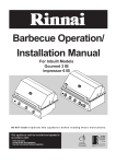
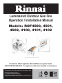
Luminaire® Outdoor Gas Fire Operation / Installation Manual Models: ROF4500, 4501, 4502, 4100, 4101, 4102 A luminous effect appliance. Not certified as a space heater. FOR OUTDOOR USE ONLY - this appliance shall not be installed or used indoors This appliance shall be installed in accordance with: • Manufacturer’s Installation Instructions • Current AS/NZS 3000, AS/NZS 3500 & AS 5601 • Local Regulations and Municipal Building Codes This appliance must be installed, serviced and removed by an Authorised Person. All Rinnai gas products are A.G.A. certified. Distributed and serviced in Australia under a Quality System certified as complying with ISO 9001 by SAI Global REGULATORY INFORMATION This appliance must be installed by an Authorised person. The installation of gas must conform to local regulations. The installation must also comply with the instructions supplied by Rinnai. Your Rinnai Luminaire® Outdoor Gas Fire has been approved by the Australian Gas Association. The A.G.A. Approval Number is shown on Data plate. Please keep this instruction booklet in a safe place for future reference. The Rinnai Luminaire® Outdoor Gas Fire does not need to be installed by a registered gas fitter if connecting to a 9 kg LPG cylinder. WARNINGS • WARNING • • • • • • • • • • • • • • • Installations and connections for Universal LPG and NG connections must be completed by a certified gas fitter when installed in reticulated system. Improper Installation, adjustment, alteration, service or maintenance can cause property damage, personal injury or loss of life. For assistance or additional information consult an authorised person. This appliance is for OUTDOOR use only. Refer to page 7 for details. DO NOT operate appliance indoors. DO NOT store or use petrol or other flammable vapours and liquids in the vicinity of this Rinnai Luminaire® Outdoor Gas Fire. DO NOT operate in an unventilated area. Refer to page 7 for details. DO NOT obstruct the flow of air around this appliance whilst in use. Refer to “Clearances and Location” section page 7. Certain materials or items when placed near the Rinnai Luminaire® Outdoor Gas Fire may be affected by the radiant heat and could be damaged. Keep all items away from your Rinnai Luminaire® Outdoor Gas Fire. Refer page 3 for details. Keep Rinnai Luminaire® Outdoor Gas Fire away from combustible materials. Maintain the Clearances as shown on page 7 and page 14. DO NOT light unit or attempt to light this appliance with the stainless steel Weather/Cover on. DO NOT place cover on while unit is operating. DO NOT use with any other gas than that stated on data label. NOT TO BE USED AS A COOKING APPLIANCE. NOT TO BE USED FOR ANY OTHER PURPOSE OTHER THAN A LUMINOUS EFFECT GAS FIRE. DO NOT USE TO DRY CLOTHES. DO NOT USE SOLD FUELS, WOOD, HEAT BEADS ETC. ON THIS APPLIANCE. ONLY USE BURNER MATERIAL SUPPLIED. WARRANTY INFORMATION Ensure you read and understand the separate Warranty terms and conditions form accompanying this appliance. Please keep these instructions in a safe place for future reference Please take a moment to complete the following information: Rinnai Australia Your Retailer: ______________________________________________ Name: ______________________________________________ Address: ______________________________________________ Telephone No. ______________________________________________ Date of Purchase: ________ / ________ / _______________________ - ii - Rinnai Luminaire® Outdoor Gas Fire - Operation and Installation Manual TABLE OF CONTENTS REGULATORY INFORMATION ..............................................................................................ii WARNINGS ..............................................................................................................................ii WARRANTY INFORMATION ...................................................................................................ii CARTON CONTENTS ............................................................................................................ 1 ACCESSORIES CONTENTS .................................................................................................. 2 SAFETY INFORMATION ........................................................................................................ 3 CLEARANCES AND LOCATION ............................................................................................ 7 CUSTOMER INFORMATION - OPERATION ......................................................................... 8 ABNORMAL FLAME PATTERN ............................................................................................. 9 INSTALLERS INFORMATION - TROUBLESHOOTING ......................................................... 9 SERVICING ............................................................................................................................. 9 SPECIFICATIONS ................................................................................................................ 10 INSTALLATION APPLICATIONS .......................................................................................... 12 GAS CONNECTION .............................................................................................................. 13 APPLIANCE LOCATION ....................................................................................................... 14 KITSET INSTALLATION - NON COMBUSTIBLE FRAME .................................................... 15 KITSET INSTALLATION - COMBUSTIBLE FRAME ............................................................. 16 DOOR ASSEMBLY ............................................................................................................... 17 FASCIA INSTALLATION ....................................................................................................... 19 MASONRY INSTALLATION .................................................................................................. 21 FREESTANDING UNIT ......................................................................................................... 22 BURNER MATERIAL ............................................................................................................ 22 CHECKLIST .......................................................................................................................... 23 INSTALLERS / GAS FITTER DETAILS ................................................................................ 23 CONTACT INFORMATION ................................................................................................... 23 Rinnai Australia - iii - Rinnai Luminaire® Outdoor Gas Fire - Operation and Installation Manual CARTON CONTENTS Burner Only Granite Cover x 2 Granite Trim x 6 Burner Assembly x 1 Granite Cover x 2 & Granite Trim x 6 Pumice/Stones/Pebbles x 1 each Stainless Steel Weather - Cover x 1 Instruction Manual/Warranty Sheet LP Hose & Regulator Assy x 1 One Sided Unit Granite Cover x 2 Granite Trim x 6 Burner and Box Assembly x 1 Trim Bracket – 4pcs Granite Cover x 2 & Granite Trim x 6 Pumice/Stones/Pebbles x 1 each Left side Trim – 1pce M4 x 8 Pan head 10pcs Right side Trim – 1pce Top Trim – 1pce Bottom Trim – 1pce M5 x 10 Pan head - 8pcs Fascia Trim Kit Components x 1 Instruction Manual/Warranty Sheet LP Hose & Regulator Assy x 1 Lintel x 1 Stainless Steel Weather-Coverx1 Angle Brackets x 4 Two Sided See-Through Unit Granite Cover x 2 Granite Trim x 6 Burner and Box Assembly x 1 Trim Bracket – 4pcs M4 x 8 Pan head 10pcs Granite Cover x 2 & Granite Trim x 6 Pumice/Stones/Pebbles x 1 each Left side Trim – 1pce Right side Trim – 1pce Top Trim – 1pce Bottom Trim – 1pce M5 x 10 Pan head - 8pcs Fascia Trim Kit Components x2 Instruction Manual/Warranty Sheet LP Hose & Regulator Assy x 1 Lintel x 2 Stainless Steel Weather-Coverx1 Angle Brackets x 4 Rinnai Australia - 1- Rinnai Luminaire® Outdoor Gas Fire - Operation and Installation Manual ACCESSORIES CONTENTS Accessories Trim Bracket – 4pcs M4 x 8 Pan head 10pcs Left side Trim – 1pce Right side Trim – 1pce Top Trim – 1pce M5 x 10 Pan head - 8pcs Glass Door Kit: M4 x 8 - 4 pieces M5 x 10 - 2 pieces Rinnai Australia Bottom Trim – 1pce Fascia Trim Kit Components x 1 Universal LPG - NG Gas Conversion Kit - 2- Rinnai Luminaire® Outdoor Gas Fire - Operation and Installation Manual SAFETY INFORMATION Clothing or other flammable materials should not be hung from the appliance, or be placed on or near the appliance. Children and adults should be alerted to the hazards of high surface temperatures, burns and clothing ignition. Do no allow anyone to sit or lean against the appliance. Young children and the infirm should be supervised at all times when they are in the area of the appliance. Do not spray aerosols in the vicinity of this appliance while it is in operation. Most contain inflammable contents or an inflammable propellant which may ignite creating a dangerous situation. Do not use or store flammable materials near this appliance. Keep unit away from combustible materials. Combustible materials must not be placed where the unit could ignite them. Appliance must be secured into a permanent fixture. Solid fuels shall not be burned in this Rinnai Luminaire Outdoor Gas Fire. Ensure no leaves, cobwebs or any other foreign debris is on the burner material prior to lighting. People, other organisms, materials or objects that are near this appliance when it is in operation may be subjected to prolonged exposure to radiant heat. Personal injury or material damage may occur. Do not operate this appliance with the stainless steel weather cover on. Rinnai Australia - 3- Rinnai Luminaire® Outdoor Gas Fire - Operation and Installation Manual SAFETY INFORMATION CONTINUED General Safety Information WARNING • Failure to comply with these Instructions could result in a fire or explosion which could cause serious injury, death or property damage. • This appliance must be installed and commissioned by an authorised person only. • This is a permanently fixed luminous effect appliance for outdoor areas only. Not to be used for cooking, food preparation or food warming. If you smell gas: WARNING 1. Shut off gas to the appliance, at its source if possible. 2. Extinguish any open flame. 3. Perform gas leak check procedure. 4. If odour continues, immediately call Rinnai service person refer page 23. WARNING • Never connect the appliance directly to the gas cylinder / reticulated gas supply without a Regulator. • Always use the hose and regulator supplied (Universal LPG models only). • Never store your gas cylinder indoors. Gas cylinders must be stored outdoors in a well ventilated area out of reach of children or the infirm. • DO NOT test for gas leaks with an open flame. • DO NOT allow children or the infirm to operate or handle any parts of the appliance. Before Installation Check that the Rinnai Luminaire Outdoor Gas Fire supplied is correct for the gas type being used. The gas type is clearly labelled on the appliance. Dataplate is located under left hand stone cover. Appliance is labelled “Universal LPG”, or “Natural Gas”. Label is located under right hand stone cover. If the appliance is “Universal LPG” it is normally used with a 9 kg gas cylinder. However, it is possible to install appliance on a reticulated “Universal LPG” supply. ie. 45 Kg. cylinder domestic supply. Pipe sizing for reticulated Natural or Universal LPG gas supplies must be in accordance with an approved sizing chart such as the one in AS 5601. Natural Gas: 1. Must be connected to the reticulated supply either by hard plumbing or the use of an approved hose. 2. Must be installed with the pressure regulator supplied for Natural Gas. 3. Connection to the reticulated gas supply must incorporate an isolation valve. 4. The isolation valve must be closed when the Rinnai Luminaire Outdoor Gas Fire is not in use. WARNING Rinnai Australia • Ensure all PVC plastic coating material is removed before operating unit. - 4- Rinnai Luminaire® Outdoor Gas Fire - Operation and Installation Manual SAFETY INFORMATION Hose and Regulator (used with gas cylinder): 1. Where applicable a pressure hose and regulator assembly supplied with the Rinnai Luminaire Outdoor Gas Fire are suitable for use on bottled LP gas only. 2. The pressure regulator and hose assembly supplied with the appliance MUST be used. 3. Replacement pressure regulators and hose assemblies must be those specified by Rinnai for use with this appliance. 4. The pressure regulator supplied has been fixed to have an outlet pressure of 2.75 kPa. A different pressure is not suitable. 5. Propane or universal LP gas cylinders must be installed and positioned to conform with AS 5601, Appendix J - “LP Gas Cylinders”. 6. When the appliance is not in use, the hose and regulator must only be disconnected from the cylinder. The hose and regulator must not be disconnected from the unit unless it is being replaced. Such replacement must only be carried out by an authorised person. 7. Inspect the gas hose when replacing the gas cylinder, or once per year, whichever is more frequent. If the hose is cracked, cut, abraded, discoloured or damaged in any other way, the Rinnai Luminaire Outdoor Gas Fire must not be used. The hose must be replaced if damaged or when local regulations require this. Contact your supplier or local regulating authority if uncertain. Such replacement must only be carried out by an authorised person. Gas Cylinder 1. This Rinnai Luminaire Outdoor Gas Fire is designed for use with a 9 kg LP Gas cylinder. This cylinder should conform to AS 2030.1 - 1999. 2. The Rinnai Luminaire Outdoor Gas Fire is designed for use in the vapour withdrawal mode. Therefore it is important to always store and use the gas cylinder in an upright position. 3. For storage and when refilling / exchanging cylinders, disconnect the hose and regulator at the cylinder end only. DO NOT disconnect the hose and regulator from the appliance end. 4. The gas cylinder should be refilled by a reputable gas dealer, or exchanged at a reputable gas cylinder exchange outlet. Gas cylinders should be inspected and re-qualified periodically in accordance with local statutory regulations. A dented or rusty gas cylinder may be hazardous and should not be used. 5. DO NOT subject the gas cylinder to excessive heat. 6. Always close the cylinder valve when this unit is not in use. 7. Gas cylinders must be stored outdoors in a well ventilated area out of reach of children and must not be stored in a building, garage or any other enclosed area. 8. When in use Gas Cylinders must be installed and positioned to conform with AS 5601 Appendix J “LP Gas Cylinders”. Rinnai Australia - 5- Rinnai Luminaire® Outdoor Gas Fire - Operation and Installation Manual SAFETY INFORMATION Gas Installation Using a Gas Cylinder Step 1. Read and understand the information in this manual, in particular the items under "Safety Information". Step 2. Ensure the control knob is in the "OFF" position as shown. OFF Step 3. Connect the regulator to the gas cylinder by turning the coupling nut anti-clockwise to tighten to a full stop (left hand thread). The seal has now engaged. An additional one half to three quarter turn is required to complete the connection. If your regulator has a plastic type hand wheel DO NOT use tools. Tighten by hand only. Use a spanner on brass hexagon type nuts, DO NOT over tighten. Step 4. Make a soapy solution by mixing one part liquid detergent (such as dish-washing liquid) and four parts water. Step 5. Open the gas valve on the cylinder by turning it anticlockwise. Step 6. Apply the soapy solution to all visible gas connections in the vicinity of the cylinder and regulator. Gas leaks will show as small bubbles gradually increasing in size in the soapy solution. Step 7. If there is a gas leak from the connection between the regulator and gas cylinder, close the gas valve on the cylinder by turning it clockwise. Disconnect the regulator and hose assembly from the cylinder by turning the coupling nut clockwise to disengage. Inspect for debris inside the cylinder fitting and the fitting at the end of the regulator. Remove debris and reconnect as per step 3). Retest for gas leaks. ON OFF Step 8. Removal of the gas hose, regulator and cylinder is the reverse of the connection procedure. CAUTION If there is still a gas leak from the connection between the regulator and gas cylinder or any other connections contact your gas supplier or Rinnai for assistance. Connections other than the connection between the regulator and gas cylinder must only be altered by an authorised person. If gas leaks are present DO NOT operate the Rinnai Luminaire® Outdoor Gas Fire. Rinnai Australia - 6- Rinnai Luminaire® Outdoor Gas Fire - Operation and Installation Manual CLEARANCES AND LOCATION Clearances The following minimum clearances from combustible materials must be maintained: • Top: 1000 mm - measured from top of cover in the closed position. • Rear: 1000 mm - measured from the rear main panel. • Sides: 300 mm - measured from the side main panel. • Openings around the base of the appliance provide air for cooling and combustion and must not be obstructed. Location ‘Outdoor Use’ is defined as use in an above ground, open air situation with natural ventilation, without stagnant areas and where gas leakage and products of combustion are rapidly dispersed by wind and natural convection. The following figures are diagrammatic representations of ‘Outdoor Use’ as defined: An enclosure with walls on all sides, but with at least one permanent opening at ground level and no overhead cover. Within a partial enclosure that includes an overhead cover and no more than 2 walls. Within a partial enclosure that includes an overhead cover and more than 2 walls the following shall apply: • At least 25% of the total wall area is completely open and • At least 30% of the remaining wall area is open and unrestricted. In the case of balconies at least 20% of the total wall area shall be and remain open and unrestricted. Rinnai Australia - 7- Rinnai Luminaire® Outdoor Gas Fire - Operation and Installation Manual CUSTOMER INFORMATION - OPERATION The Rinnai Luminaire Outdoor Gas Fire is easy to operate via the use of the control knob on the front of the Fire. All Rinnai appliances meet or exceed the safety Australian standards required for gas regulations. Your Rinnai Luminaire Outdoor Gas Fire has the following safety devices: • • Burner lights with a low gas rate (lights to pilot). Flame failure device, if the gas is on and there is no flame the gas is automatically shut off. Before starting the appliance When starting the appliance for the first time ensure all packing and packaging materials has been removed. This includes protective pvc coating to stainless steel and foam protection. Before starting ensure that debris such as leaves or other objects are cleared from the unit, doors are open, cover removed and the gas is turned on. Operating the appliance Step 1. Press the control knob and S-L-O-W-L-Y turn counterclockwise until you hear a click. This step is ‘lighting to pilot’ and you are looking for the pilot flame in the pilot flame housing. OFF position At this point the pilot Pilot light should be (turn slowly to this position visible continue to unit you hear a “click”) hold the knob down. Step 2. Keep holding down for a further 5 seconds to active the flame and then release. Steps 1 & 2 may need repeated several times to ignition the Fire. If main burner has not ignited within 5 attempts see troubleshooting section refer to page 9. Step 3. Once the appliance is on it is best to run on a high setting for a period of time in order to establish a flame pattern and allow the unit to heat up, approximately 30 minutes. You can adjust the flame by selecting between the high and low settings. OFF High Setting Pilot Low Setting Step 4. To turn off press the control knob and turn clockwise to the ‘OFF’ position. When shutting down your Rinnai Luminaire Outdoor Gas Fire it is important you replace the cover once the Unit has cooled down. Step 5. If using ULPG gas cylinder ensure you turn ‘OFF’ at the isolator valve at the cylinder. . • Outdoor Fires are not fully weatherproof and should NOT be directly exposed to the rain. A stainless steel cover has been provided with the unit to protect the burner and burner material when not in use. • Remember to remove the cover before starting this appliance. It is recommended when positioning the appliance, that it is in a location that is protected/covered to prevent full exposure to the rain. CAUTION . WARNING Rinnai Australia • REMOVE THE WEATHER COVER BEFORE LIGHTING. • DO NOT OPERATE APPLIANCE WITH THE COVER ON. -8- Rinnai Luminaire® Outdoor Gas Fire - Operation and Installation Manual INSTALLERS INFORMATION - TROUBLESHOOTING Symptom Causes • No Gas • • • • Air in gas pipe Unit will not light Minor popping sound during ignition Major popping sound during ignition or during operation Burner does not immediately stop burning when unit is turned off • • • • Incorrect gas type Faulty control valve No Spark Unburnt gas coming through pumice/stones igniting • • • • • • Incorrect gas type Damaged burner Blocked burner Unbalanced burner material • • • • Solution Check that the gas is turned on Check cylinder is not empty Repeat lighting sequence five times until gas has replaced air in hose or pipe. Ensure gas type is correct for appliance. Contact Rinnai see details page 23. • No action, normal operation. Check gas type is correct for appliance. Contact Rinnai see details page 23. Inspect and clean burner ports Inspect burner material refer to page 22 for correct positioning. • Check gas pressure is correct for appliance. • No action, normal operation • Incorrect gas pressure • Reside of gas in pumice continues to burn ABNORMAL FLAME PATTERN Rinnai Luminaire Outdoor Gas Fire has a distinct flame pattern. This should look the same every time you start your Fire, after an initial warm up period of approximately 30 minutes. Abnormal flame performance and flame pattern can indicate a problem with your appliance, such as blocked gas injectors or burner material has shifted from when the unit was first installed. There are some warning signs that could indicate a problem. • • • • • • Unusual smell from the appliance. Continued difficulty or delay in establishing a flame. Flame appears either very short or very long. Flame only burns part way across the burner. Soot building up on the inside of the glass door or burner material. If any of the above signs occur, please contact Rinnai. Normal . Abnormal SERVICING To keep your Rinnai Luminaire Outdoor fire performing in top condition. Rinnai recommends that you To keep your Rinnai Luminaire Outdoor fire performing in top condition. Rinnai recommends that you have it serviced every 2 years by a qualified service person. Regular servicing is not covered by the Rinnai warranty. Do not attempt to carry out any service work other than that mentioned in the troubleshooting section If you have any other faults or problems, please refer to your installer or contact Rinnai. Rinnai Australia -9- Rinnai Luminaire® Outdoor Gas Fire - Operation and Installation Manual SPECIFICATIONS Open Fronted Radiant / Convector Rinnai Luminaire Outdoor Gas Fire with manual control. Comes in 3 designs: • Freestanding table top unit • Open One sided cabinet • Open Two sided see-through unit Gas Type: Universal LPG / NG (with optional glass bi-fold doors) (with optional glass bi-fold doors) Suitability: This is a permanently fixed luminous effect appliance outdoor areas only. Not to be used for cooking food preparation or food warming. Burner Combustion Method Data Plate Pressure Test Point Regulator Safety Devices Flue Gas Outlet Weight 304 stainless steel tube burner Aerated bunsen type burner Left hand side of burner under granite cover Gas control valve consisting of an inlet connection, Piezo ignitor, thermocouple flame failure and manual control knob. The valve operating sequence is to turn the valve to the pilot position before lighting the main burner. Only, when the pilot has established can the gas valve be turned to high and low combustion settings. 9 kg ULPG Cylinder: Quick Disconnect (QDC) NG: 5/8” UNF flared connection to ‘Rectus Type 21’ NG Regulator Intermittent pilot ULPG: 45-25 MJ/h (High to Low) NG: 41-22 MJ/h (High to Low) SIT® single injector pilot assembly with fixed aeration and replaceable fixed pilot injector for NG and ULPG. Pilot assembly also contains a pilot ignition electrode and thermocouple for flame failure. Burner is supplied through an aluminium pipe from the gas control to the burner injector block. Pilot burner is supplied gas via aluminium pipe directly from the gas control. Incorporated into main burner injector block measuring burner pressure Pressure regulator with exchangeable spring for NG Light to Pilot and Flame Failure Safety Device (FFD) Top Louvre discharge (Cabinet models only) Burner Assembly: 20 kg Body Assembly: 30 kg (Burner + Body: 50 kg) Pilot Injector Main Injector Test Point Pressure (High) Test Point Pressure (Low) Minimum Supply Pressure Maximum Supply Pressure # 35 1.90 mm 2.45 kPa 0.80 kPa 2.50 kPa 3.50 kPa Gas Control Gas Connection (ULPG) Ignition System Input Pilot Internal Piping ULPG NG # 62 3.60 mm 0.43 kPa 0.13 kPa 1.13 kPa 3.50 kPa Include Dimensions With Fascia & Doors - mm (fascia add 40 mm) Rinnai Australia - 10 - Rinnai Luminaire® Outdoor Gas Fire - Operation and Installation Manual SPECIFICATIONS CONTINUED Burner Assembly The major component of the Rinnai Luminaire Outdoor Gas Fire is the burner assembly. This consists of a tube burner mounted in an open tray filled with pumice and stones/pebbles. A SIT® pilot burner is positioned along the tube burner to ensure positive lighting and is covered by a perforated guard to prevent the pumice from blocking the burner. The gas control, pressure regulator and spark igniton system is positioned at the right end of the tube burner. The complete assembly is housed within a stainless steel body incorporating a removable cover. The cover is placed over the burner for protection from wind and rain when the unit is not in use. DO NOT attempt to light the appliance when the cover is in place. DO NOT place the cover on the appliance when the flame is on. Body Assembly - (Open One Sided Cabinet) The outer body assembly is optional and must be used if installing into a non combustible enclosure. It consists of a 5-sided construction with an open front (pictured) or open front and back. If a body assembly is ordered, this comes assembled complete with burner assembly inside. Enclosure must be constructed of masonry or noncombustible material. Body Assembly with Glass Bi-Fold Doors The body assembly has optional tempered glass double bi-fold doors to reduce the affect of wind and rain on the burner. The appliance can operate with the doors open or closed. The unit is able to operate with the bi-fold doors closed. Air being induced into the combustion chamber through the lower half of the open front and expelled out the top or through the top louvres on the glass door. Closing the bi fold doors does not affect the operation of the appliance. Adequate ventilation is supplied via the louvres and gaps at the side and top of the unit. Rinnai Australia - 11 - Rinnai Luminaire® Outdoor Gas Fire - Operation and Installation Manual INSTALLATION APPLICATIONS The Rinnai Luminaire Outdoor Gas Fire is designed and required to be built into a permanent fixture. The table below details the available installations options, components needed and optional accessories. Installation Components Needed Optional Accessories Freestanding Unit • Burner Assembly Universal LPG • NG Conversion Kit Open One Sided Unit • One Sided Assembly • Glass Bi-Fold Doors • NG Conversion Kit Open Two Sided See-Through Unit • Burner Assembly Universal LPG • Glass Bi-fold Doors • NG Conversion Kit Non-combustible enclosed masonry, open one or two sides • Burner Assembly Universal LPG • NG Conversion Kit Comes complete with burner assembly Rinnai Australia - 12 - Rinnai Luminaire® Outdoor Gas Fire - Operation and Installation Manual GAS CONNECTION Connecting a 9 kg LPG Cylinder A Quick Disconnect (QDC) gas connection is provided with the hose and regulator. Step 1. Place the gas cylinder onto a supporting base. Step 2. Fasten regulator and hose assembly to cylinder valve outlet. Tighten firmly. When connecting the hose and regulator assembly to the gas cylinder, take care to avoid unnecessary twisting of the flexible hose. DO NOT over tighten connection. Step 3. Open the gas cylinder valve one full turn to allow the gas to flow. Step 4. Leak test all accessible connections thoroughly using a soapy water solution (1 part liquid detergent and 4 parts water) prior to using the appliance. Bubbles will appear if connections are not properly sealed. Tighten or rectify as necessary and retest. Step 5. Refer to page 6 for full instructions. Fixed Universal LPG and NG Connections Fixed Universal LPG connection Natural Gas WARNING CAUTION Rinnai Australia A 3/8” BSP fixed connection is also supplied with this unit. This connection is for installations connected to a permanent fixed Universal LPG connection (that supplies gas to other appliances in the premises). In order to connect to NG a conversion kit is required. This can be purchased as an accessory item available from Rinnai. Installation and connections for fixed NG and Universal LPG connections must be completed by a certified gas fitter. The Stainless Steel flexi pipe is to be drawn through the base of the unit. Ensure it is bent evenly and not kinked. See “Gas positioning diagram” on page 21 for dimensions and positioning of the gas line opening. - 13 - Rinnai Luminaire® Outdoor Gas Fire - Operation and Installation Manual APPLIANCE LOCATION The Rinnai Luminaire Outdoor Gas Fire must be installed as a permanent fixture in an outdoor area. Determining and consideration of the position for the Rinnai Luminaire Gas Outdoor Fire will be dependent on the configuration of the unit purchased. Additional considerations such as protection from direct rain, wind and sea spray, openable windows, debris from trees as well as location to neighbouring properties also needs to be considered, gas supply and clearances from combustibles will influence where you can position this appliance. Location will also be depended on the type of unit purchased and if being installed into a combustible cavity. General Clearances Inbuilt Freestanding A C ang Mantel B D Additional structure or sidewall rh r Ove Roof o 1m m 100m 1m m 100m 300mm 1m 300mm E = 900mm Min. . 600mm Max. E - min. 100mm 0mm Max 128 Minimum of 2 x 200 cm2 ventilation slots to be incorporated into the structure. One at the top of the storage area and one at the base. Structure Clearances Required Additional Detail Below eaves, balconies or other projections (A) 1000 mm minimum If the projection is a shade cloth or material awning then this is deemed as a combustible material and the recommended clearance is 1500 mm. From the ground or other surface (E) Inbuilt - 100 mm minimum Ground level to bottom of fireplace. Freestanding - 900 mm minimum Walls (D) 500 mm Side of unit to side wall. Gas Meters 1000 mm Drain of Soil Pipe 150 mm Openable Windows and doors 1000 mm From an openable window, door or non mechanical air inlet, or any other opening into a building with the exception of sub-floor ventilation. Mechanical Air Inlet 2000 mm For example: air conditioning unit. Mantles (B) and (C) 500 mm / 300 mm Minimum vertical clearance of 500 mm with a maximum mantle depth of 300 mm. If mantle depth is more than 300 mm you will need 1000 mm of vertical clearance. 1 m safe distance Fixed objects such as outdoor furniture, umbrellas and plants should be at least 1 m away from the unit when it is in operation. Installation specific clearances Additional clearances also need to be observed for specific installation applications, these are detailed on the following pages. Ensure clearing for servicing Ensure enough room is maintained for servicing, cleaning and general access to the appliance. When using a 9 kg gas cylinder a minimum of 2 x 200 cm2 ventilation slots must be used Ventilation of structure (1 x top and 1 x bottom = 400 cm2 total) to ensure safe ventilation of all structures housing cylinders. Rinnai Australia - 14 - Rinnai Luminaire® Outdoor Gas Fire - Operation and Installation Manual KITSET INSTALLATION - NON COMBUSTIBLE FRAME Steel framing options are available for the one sided and two sided see-through units. For ease of installation Rinnai provide the durable steel frame as a kitset. Prepare framing dimensions Construct framing to specific installation dimensions shown. To enhance the durability of the framing we suggest the frame is mounted on a paved slab 250 mm (above unpaved ground) and 150 mm (above paved ground). We also recommend having a 25 mm air gap to stop LPG from pooling and to allow moisture to drain easily from the enclosure. slab used to elevate enclosure above ground to enhance durability of framing 25 mm air gap to stop LPG pooling at base and also to allow moisture to drain easily The minimum clearances to combustible framing materials are: Above 500 mm Side 25 mm Below 0 mm Behind 30 mm (One sided cabinet) For the Open See-Through Cabinet you will need to observe these clearances on both faces. Non Combustible Combustible A = 555 mm A = 555 mm B = 1180 mm* B = 1225 mm* C (two sided) = 470 mm** C (two sided) = 470 mm** C (one sided) = 500 mm** C (one sided) = 500 mm** D = 500 mm *** D = 500 mm *** * Includes 25 mm side clearances D tel metal lin B C A ** Includes cladding (for one sided unit 500 mm dimension measures front cladding only) ng ddi cla *** If due to design this dimension required to be less than 500 mm, you will need an additional steel lintel. This can be ordered as a spare part from Rinnai. Non-combustible cladding and frame materials are required when dimension B = 1180 mm. Install body/burner assembly into frame When purchasing a cabinet option the body and burner come pre-assembled. simply unpack, fit and secure assembly into the frame using bottom fascia brackets. For the see-through unit you will need to ensure the control knob is facing the correct way for easy operation. Drill hole in bottom bracket and fit screw to secure assembly. Rinnai Australia - 15 - Rinnai Luminaire® Outdoor Gas Fire - Operation and Installation Manual KITSET INSTALLATION - COMBUSTIBLE FRAME Attach metal lintel and angled clearance brackets Luminaire Outdoor Fire cabinet options are supplied with a metal lintel and angled clearance brackets. These are required for installations where combustible framing is used. • • Metal lintels Angled clearance brackets Open One-Sided Cabinet (1), Open See-Through Cabinet (2) Open One-sided Cabinet (4), Open See-Through Cabinet (4) Metal lintel Designed to sit about the unit and replace combustible framing in areas exposed to high temperatures. The minimum distance above the unit to a combustible frame is 500 mm. To fit Step 1. Take out and undo four fastenening screws at either end. side sections need to be rotated 180° and secured into framing above unit. Step 2. Flip side sections 180° and loosely refit screws. Step 3. Adjust to desired length before tightening. Angled clearance brackets Designed to ensure combustible framing is greater than 25 mm from the sides of the unit as shown. Top View - Open One-Sided Cabinet 1225 mm (min) timber stud clearance bracket min 500mm non combustible cladding cabinet 1180 mm (min) 1195 mm (max) Top View - Open See-Through Cabinet timber stud non combustible cladding 1225 mm (min) 470mm cabinet clearance bracket Rinnai Australia 1180 mm (min) 1195 mm (max) - 16 - Rinnai Luminaire® Outdoor Gas Fire - Operation and Installation Manual DOOR ASSEMBLY Door Assembly Installation Instructions The assembly is comprised of tempered glass double bi-fold doors with stainless steel surrounds and fixings. This offers wind protection when the unit is on and when not in use protection from wind, rain and nesting animals. The assembly fixed to the cabinet frame of the Rinnai Luminaire Outdoor Fire, so is only suitable for installations where a cabinet (also called a body assembly) has been installed. Cabinet installation - door assembly is suitable Only has a burner assembly installed - door assembly IS NOT suitable. The unit can operate with the doors open or closed, however for best radiant heat the doors should be open during operation. Suitable for Non Combustible cladding and frame materials. Rinnai accepts no responsibility for deterioration of cladding or finishes. If the doors are closed during operation DO NOT touch the glass. The glass can reach very high temperatures and cause severe burns. WARNING Rinnai Australia Young children should be supervised at all times when the unit is in operation. - 17 - Rinnai Luminaire® Outdoor Gas Fire - Operation and Installation Manual DOOR ASSEMBLY Door Assembly Installation Instruction Kit contains: The Rinnai Luminaire Outdoor Gas Fire door assembly comes flat packed in 1 box and contains the following: 1 2 3 - Component Left hand glass panel and surround Right hand glass panel and surround Swing arm kit Screws M4 x 8 (for fitting swing arms into cabinet) - Screws M5 x 10 (for fitting swing arms to doors) Quantity 1 1 1 4 2 Before Installation Has the Rinnai Luminaire Outdoor Gas Fire already been installed? If yes, you will need to remove the frame and burner assembly before fitting the doors. Fit door swing arms Remove left and right swing arms from the assembly kit. Fit into the smaller pre-drilled holes of the Luminaire cabinet using the smaller 4 pcs M4 x 8 screws provided (2 screws per mount). Install body/burner assembly The body/burner assembly needs to be fitted before the doors as doors reduce entry access into the enclosure. New Installation If you have purchased your doors with the Luminaire Outdoor Gas Fire you need to install the body/burner assembly. Simply unpack, slide into enclosure and fit granite pieces into place. Retrofit If the doors are being retrofitted the burner assembly needs to be fitted back into the cabinet. Simply reinstall by reversing steps taken to remove it, refer page 19. Fix doors to cabinet Step 1 - Slot the C-shaped door bracket over the louvre ensuring the holes line up with those on the unit. Reset door on the swing mount, this will help you level the door. Step 2 - Secure 2 pcs M5 x 10 screws into the side frame, level as best you can and fix in place with remaining 4 screws. DO NOT tighten at this stage as you will need to align both doors. See alignment page 19. Step 3 - Repeat Steps 1 & 2 with the other door. Rinnai Australia - 18 - Rinnai Luminaire® Outdoor Gas Fire - Operation and Installation Manual FASCIA INSTALLATION Align doors and attach frame brackets Step 1. Align doors and tighten, some adjustment may be necessary to square the frame. Holding the door with one hand and tightening the screws with the other is a good way to do this. Step 2. Secure 4 frame brackets provided with the Rinnai Luminaire Outdoor Gas Fire using 2 pcs M5 x 10 screws supplied. Fit doors to swing arms Step 1. Attach doors to swing arms using 8 pcs M5 x 10 screws provided. Step 2. Attach frame from the Rinnai Luminaire Outdoor Gas Fire. Removing the frame Step 1. Remove the 2 pcs M4 x 8 underside screws from the bottom of the frame. Step 2. Detach frame from the bottom, swing out and lift off the top of the upper frame bracket. Step 3. Remove the 4 frame brackets. Removing the burner assembly The burner assembly weighs approximately 20 kg, if required seek additional assistance in lifting. You may also want to remove some of the large quartz pieces to make it easier to carry. Step 1. Disconnect gas and gas connection. Step 2. Remove left and right granite plates from the burner. Step 3. Remove the large 2 pcs M5 x 10 burner mounting screws on the left and right of the burner assembly anchoring the burner assembly to the cabinet. Step 4. Carefully remove the burner and set aside. Rinnai Australia - 19 - Rinnai Luminaire® Outdoor Gas Fire - Operation and Installation Manual FASCIA INSTALLATION Fascia Installation Step 1. Unpack and remove the fascia components check to see you have all the components as listed on page 1. Step 2. Identify the top and bottom panels, these are the longest of the four panels supplied. The top panel has an additional return fold. The bottom panel has two holes for securing, see image. Step 3. Remove the protective PVC coating from all panels. Step 4. On a flat, clean surface assemble the top, side and bottom fascia panels using the 8 pcs M4 x 8 screws supplied. Step 5. Fit the four frame mounting brackets to the cabinet frame using the 8 pcs M5 x 10 screws supplied. Step 6. Position the fascia assembly by hooking the top fascia panel over the top two mounting brackets (1), then swing the assembly in at the bottom (2). The fascia assembly can then be secured into position using 2 pcs M4 x 8 screws (3). Rinnai Australia - 20 - Rinnai Luminaire® Outdoor Gas Fire - Operation and Installation Manual MASONRY INSTALLATION This is common to all installations, refer page 22 for burner material and page 4 & page 13 for gas connection. Minimum Dimensions (mm) A 500 B 1150 C 470 B A Gas connection opening C Prepare surround Construct surround to minimum dimensions provided above. Remember to allow for a gas connection opening below the burner as shown below. Ensure the opening is large enough for the flexible connection to fit through. A suggested hole size is detailed below. Gas positioning diagram Install burner assembly Install burner assembly into non-combustible surround and fix in place with appropriate fasteners. Rinnai Australia - 21 - Rinnai Luminaire® Outdoor Gas Fire - Operation and Installation Manual FREESTANDING UNIT 1m 1m m 100m m 100m 300mm 300mm E = 900mm Min. 1m . mm 600mm Max. 0 128 Max Prepare surround • • Construct surround ensuring clearances to combustibles and minimum height from ground clearance above. This needs to be a permanent and fixed construction. Remember to allow for a gas connection opening below the burner, refer page 20 for gas connection positioning. Install burner assembly • Install burner assembly and fix in place with appropriate fasteners. Install burner material and complete gas connection • This is common to all installations as below. BURNER MATERIAL WARNING Installation of the burner material is critical to correct operation of the Rinnai Luminaire Outdoor Gas Fire. Please note in each step the height at which the pumice, quartz stones or pebbles should sit. Layer 1 - Pumice Fill the burner tray with pumice and level to the bottom of the granite trims. Not all the pumice will be needed as more has been supplied than necessary. Keep remainder for top up next season. Avoid pouring over the burner, dust particles can clog the burner ports. Ensure burner is not deeply buried by the pumice. Granite trim Burner 1st Pumice Cross section detail Layer 2 - Quartz Stones Using all the small quartz stones provided, place a single layer of small quartz stones evenly covering the entire top of the pumice. Granite trim 2nd Quartz Stones Cross section detail 1st Pumice Burner Layer 3 - Quartz Pebbles Place the 14 pieces of large quartz pebbles on top of the small quartz stones. DO NOT COVER PILOT FLAME HOUSING. Refer page 8. WARNING DO NOT STACK THE PEBBLES. The pebbles may roll off and cause personal injury or damage to surrounding surfaces. Rinnai Australia Granite trim 3rd Quartz Pebbles 2nd Quartz Stones Cross section detail 1st Pumice Burner - 22 - Rinnai Luminaire® Outdoor Gas Fire - Operation and Installation Manual CHECKLIST (To be completed by the Installer) Serial No: _______________________________ NO YES 1. Is the appliance positioned in a suitable location with regards to clearances? 2. Is the unit fixed in location? 3. Is the Pumice / Stones / Pebbles positioned correctly? 4. Is the LPG gas cylinder securely positioned? 5. Is the LPG gas cylinder storage area correctly ventilated? 6. Have all gas connections been checked for leaks using a soapy water solution? 7. Have you instructed the owner of the correct operation of this appliance before leaving. • Ensure all PVC plastic coating material is removed before operating the unit. WARNING • If you have answered no to any of the above questions you must not allow the appliance to be operated until the item has been rectified. INSTALLERS / GAS FITTER DETAILS INSTALLERS / GAS FITTER DETAILS Company name: ____________________________________________________ Installers name: ____________________________________________________ Address: ____________________________________________________ ____________________________________________________ ____________________________________________________ Phone: ( )__________________ Mobile: ____________________ Certificate of Compliance / Certification Number:__________________________ (* where applicable) Authorised Persons – License Number: _______________________________ Signed:________________________ Rinnai Australia Date:___________________ - 23 - Rinnai Luminaire® Outdoor Gas Fire - Operation and Installation Manual Notes: CONTACT INFORMATION Australia Pty. Ltd. Head Office 10-11 Walker Street, Braeside, Victoria 3195 P.O. Box 460 Tel: (03) 9271 6625 Fax: (03) 9271 6622 Head Office, New Zealand 105 Pavilion Drive Airport Oaks, Mangere, New Zealand Tel: (09) 625 4285 Fax: (09) 624 3018 Rinnai Australia ABN 74 005 138 769 Internet: www.rinnai.com.au E-mail: [email protected] National Help Line Spare Parts & Technical Info Tel: 1300 555 545* Fax: 1300 300 141* *Cost of a local call Higher from mobile or public phones. Internet: www.rinnai.co.nz E-mail: [email protected] 24 Hour Service Tel: 0800 746624 (0800 Rinnai) - 23 -Luminaire®Outdoor Gas Fire-Op/Inst.Man 08-026 V3(14/5/10)NZ P/No 11283 Issue C