1
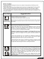
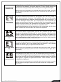
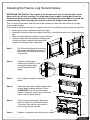
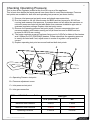
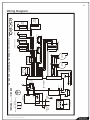
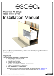
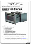
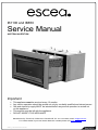
IB1100 and IB850
Service Manual
AUSTRALIAN EDITION
Important
•
•
•
•
•
This appliance must be serviced every 12 months.
Any service operation should be carried out only by a suitably qualified and trained person
Gas and electricity supply MUST be isolated before any service operation is carried out
on this appliance.
This manual must be left with the appliance.
DO NOT MODIFY THIS APPLIANCE
Manufactured by: Escea Ltd, PO Box 5277 Dunedin NZ, Ph: +64 3 479 0302, email: [email protected]
For contact details of your local escea distributor or dealer please visit www.escea.net
G8872_7 Service Manual AU.doc
2
Contents:
Page:
Error Codes
3
Cleaning the Log Set and Glass
5
Checking Operating Pressure
6
Removing / Cleaning Fan
7
Removing Electronic Drawer
8
Replacing a Wireless Control
9
Gas Type Conversion
10
Annual Service Procedure
11
Wiring Diagram
12
G8872_7 Service Manual AU.doc
3
Error Codes:
This gas fire has been designed to show error codes to help explain and identify any fault
situation that occurs.
These codes will appear on the wireless control in the form of a large letter “E” with a number
beside it. Codes can normally be reset by turning the heater off at the wall then on again.
The following table shows what each code means and possible ways to rectify the situation.
In the case of persistent or repeated shutdown errors, action must be taken immediately to find
and repair the fault.
Error Code
Suggested action
- Usually insufficient cavity ventilation.
- Possibly outer fascia panel installed incorrectly.
(Printed Circuit Board)
Note: This error has a permanent lock out and will require the unit to be reset 10 minutes
after the initial error (turning the power to the fire off "at the wall" then on again after a
few seconds).
Flame Failure
The fire has tried to light three times and failed.
- Check gas supply and check other gas appliances to see if they are
affected. If you have two separate propane cylinders, switch over to the
full bottle or contact your gas supplier. You may need to retry igniting the
fire a few times after re-establishing gas supply.
PCB Over Temp
- Check the electrode placement in relation to the flame. Ensure it is well
enveloped in flame as per the diagram in the installation instructions.
Ensure no coals have dropped onto the ignition electrodes between the
burners.
- Ensure the electrodes are not contacting any metalwork including the
burners and that they have the correct air gap. Check that the spark
electrode is positioned in front of a port in the front burner.
- Check that there has not been a significant reduction in pressure inside
the house (such as an extractor fan in a nearby kitchen) which can pull
flue gas back down through the firebox "snuffing" the flames.
OR
The bimetallic snap disk mounted on the hood of the draught diverter at
the rear of the fire or on the lid of the fire has tripped. The possible causes
for this could include:... A gust of wind pushing exhaust gases back down
the flue OR a significant reduction in air pressure inside the house or
cavity which is pulling exhaust gases back down the flue (such as a
extractor fan in a nearby kitchen).
If installed into a tight masonry cavity it may indicate that the whole
installation is getting too hot and some additional ventilation into the cavity
may be required.
G8872_7 Service Manual AU.doc
4
Draught Diverter
Bimetallic Trip
In the unlikely event that the fans have stalled, and the snap disk on the
lid of the fire has tripped, this would show an E3 also. Simply check that
the fans are running normally after resetting and running the fire again.
Note: This error has a permanent lock out and will require the unit to be reset 10 minutes
after the initial error (turning the power to the fire off "at the wall" then on again after a
few seconds).
Valve Solenoid
Check Failure
Remote cannot
communicate with
fire
The valve solenoids have failed the pre-ignition test. This is to detect a
faulty valve solenoid. However, it is possible that some of the wiring
connections between the resistors and the solenoids are not secure, or a
wire has dislodged. Check that the connections to each solenoid and
resistor are secure and in place. It may be that the connections on the
ends of the wires need to be tightened a little (eg with a pair of pliers) to
ensure a robust connection to the valve or resistor terminal.
It could also be that one of the solenoids on the valve inside the fire have
failed. If this is the case the valve will need to be replaced.
The remote cannot communicate with the fire. Reasons for this could
include the fire being off "at the wall" i.e. a loss of power to the fire or the
remote is outside of its effective radio frequency range (too far away from
the fire). Typical remote range is 1m to 12m. Ensure there is power to the
fire by pressing the auxiliary on/off (red) button on the fire, then press the
on/off button on the remote to clear the error.
The valve temperature sensor has detected abnormally high temperatures
around the valves. This is an unlikely fault and should it occur please
contact the Escea agent you purchased the fire from.
Valve Temp Sensor
Trip
Temp Sensor Error
Note: This error has a permanent lock out and will require the unit to be reset 10 minutes
after the initial error (turning the power to the fire off "at the wall" then on again after a
few seconds).
This indicates a fault with one of the two temperature sensors installed in
your fire. Resetting the fire (turning the power to the fire off then on again
after a few seconds) and if the fault reappears, please contact your Escea
sales agent to organise a replacement sensor. These sensors must not
be disabled or bypassed.
Note: This error has a permanent lock out and will require the unit to be reset 10 minutes
after the initial error (turning the power to the fire off "at the wall" then on again after a
few seconds).
G8872_7 Service Manual AU.doc
5
Cleaning the Fascia, Log Set and Glass:
NEVER RUB THE FASCIA. The outside of the fascias must only be cleaned with a clean
damp cloth, dry off after cleaning. The high temp silver powder coating that is used on
Escea fascia parts contains certain amounts of aluminium that when rubbed too hard will
oxidise leaving a black smudge that cannot be removed. Always clean when cold.
This is a service procedure that will need to be carried out when ever soot builds up on logs
and/or inside of glass.
If soot build up becomes excessive or regular then one of the following actions may be required;
• Reset gas pressure, pressure may be too high;
• Reposition log set so that front edge of each log is just behind each row of holes in burner
top;
• Clear any blockage from primary air port of burner;
• Check to make sure flue system is drawing well
or that there are no adverse environmental
conditions inhibiting clean combustion.
Step 1:
Lift off the inner fascia by removing
the screws attaching the bottom of
the fascia to the firebox and lifting
it up and off.
Step 2:
Unscrew the top glass
retainer and remove it. Take
care that the glass does
not fall forwards at this
stage.
Step 3:
Lift out glass and place it carefully
aside.
Step 4:
Clean the inside and outside of glass with
normal glass cleaning products. Use a
CLEAN DRY cloth to remove cleaner
residue. Stubborn marks may be cleaned
with a ceramic glass cleaner.
Step 5:
Take out log set and gently brush any
soot from log with a soft hearth brush.
The burner tops can be vacuumed to
remove any excess material.
Step 6:
Replace in opposite order and test run heater.
G8872_7 Service Manual AU.doc
6
Checking Operating Pressure:
This is done at the regulator located at the front RH corner of the appliance.
This is best done before the fascia panels have been fitted to avoid fascia damage. Pressure
test points are available for both inlet and operating test pressure (as shown below).
1) Remove inlet pressure test point screw and attach manometer tube.
2) Run the heater on full (all three burners for IB850 and two burners for IB1100 are
running) and measure inlet pressure. If pressure does not fall within the maximum or
minimum pressures listed on the table below then reassess installation pipe size or
upstream regulator settings. Replace inlet test point screw.
3) Remove the operating pressure test point screw. Connect manometer tube and
measure pressure with heater running on full (all three burners for IB850 and two
burners for IB1100 are running).
4) The heater regulator pressure has been factory set to 0.87kPa for Natural Gas heaters
and 2.30Kpa for LPG (PROPANE) heaters. Please check that the operating pressure
is exactly as listed and if not, adjust screw in centre of regulator until pressure is
correct.
5) Replace operating test point screw and leak test both test points.
B
C
D
A
A = Operating Pressure test point
B = Pressure adjustment screw
C = Inlet pressure test point
D = Inlet gas connection
IB850 and IB1100 Pressure Table
Gas Type
LPG (PROPANE)
NG
Minimum Inlet Pressure
2.5kPa
1.2kPa
Maximum Inlet Pressure
5.0kPa
5.0kPa
Operating Pressure
2.30kPa
0.87kPa
G8872_7 Service Manual AU.doc
7
Removing or Cleaning Fan
As part of regular service procedure, it is recommended that the fan is removed for cleaning.
Dust will build up on the fan rotor and in the cavity where the fan is located. This can be removed
by the service person using a hearth brush and a vacuum cleaner.
Step One:
ISOLATE THE POWER TO
THE FIRE BEFORE PROCEDURE
Remove front glass,
log set and log bracket as
described on page 5.
To remove the log bracket
take out the screws securing
it to the firebox.
Step Two:
Remove firebox from heater
by taking out the two screws
attaching the front lid + the
screws in each corner of the
firebox. Then remove the screws
in the base of the firebox, and
pull fire directly outwards
(as shown).
Remove screws from
each corner of firebox
Remove screws
from firebox base,
lift lid and pull
firebox out
Step Three:
Take out the 7 screws on
top of fan plate assembly.
Step Four:
Lift the fan unit up and
out as far as the wiring loom
will allow. Unplug wires to
fully remove fan assembly.
Step Five:
Clean fans and area around valves,
removing all dust build up.
Replace fans and fire box.
Step Six:
To replace fan assembly and firebox
repeat these steps in reverse order.
Pull up and outwards
G8872_7 Service Manual AU.doc
8
Replacing Electronic Drawer
ISOLATE THE POWER TO THE FIRE BEFORE PROCEDURE.
All of the electronic components of the heater have been located on a removable drawer.
This drawer is located on the left hand outer side of the IB850 and IB1100. On the back of the
drawer are two large connectors that unplug as the drawer is removed so only the three wires
connecting the electronics to the ignition and flame rods must be removed manually from the
PCB (Printed Circuit Board).
Step one: Remove outer fascia by taking out two screws located behind the bottom fascia trim
panel.
Step Two:
Take out the two screws at each end of the
electronic drawer and pull drawer directly
outwards.
Step Three:
Carefully remove the two wires shown
from the white ignition module.
Wire Entry:
IB850
& IB1100
1. Flame Rod
2. Spark Lead
Note: It is important that the
flame rod & spark lead wires sit
in this position in the electronic tray.
G8872_7 Service Manual AU.doc
9
Replacing a Wireless Control:
If the wireless control becomes lost or damaged, a new one can be ordered from any Escea
retail agent.
When you have the new remote, the following procedure needs to be followed to “teach” the
remote to only communicate with that fire.
1. Ensure the fire and remote are set to “Off” (only the time is displayed on the remote).
R
FAN
BOOST
ER
ME
TIM
3. Press and hold the – (minus) button until the two large temperature digits
reading 00 start to flash slowly. Release the – (minus) button. The remote
control is now ready to be addressed to the fire.
C
SET
FLAME
EFFECT
ONLY
SE
TI
2. Press the – (minus), + (plus) and the Fan Boost buttons simultaneously
until all the characters on the display light up. This will put the remote into
test mode and the two large temperature digits should be reading 00.
LE
CT
A CT
IVA
TE
SET TIME
4. Press and hold the red auxiliary on/off button on
the fireplace for a minimum of eight seconds, or until
the two large temperature digits start counting
upwards from 00 to 99 repeatedly.
Red auxiliary
Button
Note: Pressing the red auxiliary button on/off button will start the fire. Once the remote control is
counting the fire can be turned off by pressing the red auxiliary button again.
5. Press the large power button in the middle of the remote control to exit the test mode and
return to normal operation. The remote should only be displaying the time. Check the fire will
start using the remote control by pressing the large power button. Turn it off again using the
remote control.
6. The fire is now re-addressed to the remote control.
Gas Type Conversion
Gas type conversion kits can be ordered from your Escea retailer under the following part
numbers;
811220
811221
811222
811223
Natural Gas Conversion Kit - IB850
Propane Conversion Kit - IB850
Natural Gas Conversion Kit - IB1100
Propane Conversion Kit - IB1100
If the heater had not been used before gas type conversion was required then Escea will credit
the cost of the conversion kit when the original parts are returned to Escea.
G8872_7 Service Manual AU.doc
10
Gas Type Conversion
Procedure:
Step One:
Remove inner fascia, glass and logs (as described
earlier in the manual).
Service person may also wish to remove the firebox
to increase the work space within the heater.
Step Two:
Take out front two burners by removing
the screws from the left hand end of the burner
top face. Burners can then be lifted out.
Step Three: (IB850 only)
Unscrew rear burner clamp bracket
on left side.
Lift out the rear burner.
Step 3
Step Four:
Change the three jets (two jets
in IB1100) with the jets supplied
in kitset. Replace the rear burner and
clamp bracket (IB850 only).
Replace front two burners with the
burners supplied in kitset.
Step Five:
Take the regulator spring out of the regulator
by unscrewing the pressure adjustment knob
completely. Swap regulator spring with the
new spring that is supplied in conversion kitset.
Replace adjustment screw.
Step Six:
Reset gas pressure as per instructions
on page 6 of this manual.
Step Seven:
Cover the existing gas type label with the new
gas type label supplied in kitset. Ensure
serial number and date of manufacture
are still visible. Write your name,
company (if appropriate) and date
of conversion on new label with
permanent marker.
Replace firebox and fuel media.
G8872_7 Service Manual AU.doc
Step 4
Step 5
Step 7
11
Annual service procedure:
1. Isolate power to fire.
2. Remove front glass and clean inside of glass.
3. Remove logs and brush off any soot.
4. Remove burners and blow compressed air through the burner
ports.
5. Remove jets and clean injector hole with solvent.
6. Remove firebox to give access to fan, brush and vacuum any
dust build up from fan blades.
7. Vacuum any dust from the cavity that houses the fan and
solenoid valves and from the ducts down each side of the heater
that lead to this cavity.
8. If the gas piping includes a flexible hose connected to the
regulator, check the hose for signs of wear (discolouration, loss of
flexibility, cuts, worn covers, cracks, crushing, kinking, flattening or loose
end fittings) and replace if worn, or more than five years old.
9. Test all joints for gas tightness.
10. Reassemble heater and check that operating pressure is
correct. 2.3kPa LPG (PROPANE), 0.87kPa Natural Gas with all
burners running.
11. Check glass & firebox tape and replace if necessary.
11. Check to make sure that flue system is intact and not in any way
blocked. Check the flue draw with a smoke match to confirm
there is no spillage from the draught diverter.
12. Trial heater with several start/stop cycles and trial fan-boost,
flame effect only and thermostat modes to ensure that all
modes function correctly.
G8872_7 Service Manual AU.doc
12
Wiring Diagram:
IB1100
ONLY
IB850
ONLY
BURNER 3
TRANSFORMER
No Fan Over Temp
ISOLATING / BURNER 1
Draft Diverter Over Temp
BURNER 2
FAN2
Ignition Module Supply
IB850 ONLY
FAN1
AUXILIARY
ON / OFF (N/O)
CN1
CN2
CN7
CN8
J7
MAINS FUSE (2A)
SPARK
ELECTRODE
S1
GND
V2
V1
W
ANT
OPTIONAL
PHONE & INTERNET
SWITCHING MODULE
FLAME
DETECT
ELECTRODE
i
/ 50Hz 2A
Read the user instructions
before use.
FLAME IGNITION
MODULE
230V AC
CONTROLLER
GND (CN3)
V2 (CN5)
V1 (CN6)
PSW (CN9)
ANT
Manufactured by: Escea Ltd; PO Box 5277, Dunedin, NZ.
G8872_7 Service Manual AU.doc