1
®
Owners Manual
Specifications
Length......................................................................................... 43 in (1090mm)
Beam............................................................................................... 6 in (156mm)
Motor................................................................................................390-size (x2)
Weight................................................................................................5 lb(2.3 kg)
Speed Control......................................................... 50-amp waterproof with reverse
Hull Material........................................................................... Fiberglass composite
Battery............................................. 7.2V sub-C w/ Tamiya connector (not included)
Radio................................................................................ 2-channel (not included)
Servo.................................................................. Standard steering servo (installed)
www.ProBoatModels.com
Table of Contents
Table of Contents.................................................................................................. 2
Using the Manual.................................................................................................. 2
Recommended Tools and Adhesives......................................................................... 2
Recommended Radio Equipment and Batteries.......................................................... 3
General Guidelines and Safety Precautions............................................................... 3
Unpacking Your Model............................................................................................ 4
Basic Assembly..................................................................................................... 7
Accessory Installation.......................................................................................... 10
Warranty and Repair Policy................................................................................... 18
Warranty Services............................................................................................... 19
Warranty Services............................................................................................... 20
Compliance Information for the European Union...................................................... 21
Replacement Parts............................................................................................... 22
Using the Manual
Please read through the manual before you
begin assembly of your model. Remember to
take your time and follow the directions.
This manual is divided into sections to help
make assembly easier to understand, and to
provide breaks between each major section.
In addition, check boxes () have been
placed next to each step to keep track of its
completion.
Recommended Tools and Adhesives
•
•
•
•
•
•
•
Hobby knife with #11 blade
Side cutters
Medium CA
Ballast weight (5 lb or 2.2 kg)
Charger for motor battery
Pin vise
Drill bit: 5/64-inch (2mm)
2
Recommended Radio Equipment and Batteries
You will need a 2-channel transmitter and
receiver. We recommend one of the crystal®
free, interference-free Spektrum™, Pro Boat
®
or JR radio systems using DSM technology.
Pro Boat 27MHz radios
Spektrum Marine compatible
transmitters:
Please look for the Marine logo on the back
of your surface transmitter and check the
part number to confirm compatibility with
Spektrum Marine receivers.
•
•
•
•
•
•
•
• Pro Boat AM 2-Stick Radio (PRB8021)
• Pro Boat AM Pistol-Grip (PRB8040)
DX3E (SPM3160)
DX2.0 (SPM20220)
DX3.0 (SPM20320)
DX2S (SPM2120)
DX3S (SPM3140)
Pro Boat Pistol Grip 2.4GHz (PRB8060)
Spektrum and JR DSM2™ aircraft
transmitters
Batteries
In adddition, we recommend the purchase of
one of the following batteries:
•S
peed Pack 1800mAh Ni-MH 6-Cell Flat
(DYN1050)
• Speed Pack 3300mAh Ni-MH 6-Cell Flat
(DYN1070)
• Speed Pack 5100mAh Ni-MH 6-Cell Flat
(DYN1090)
www.dynamiterc.com
Spektrum Marine Receivers
• SPMMR3000
www.spektrumrc.com
The Spektrum trademark is used with
permission of Bachmann Industries, Inc.
US patent 7,391,320. Other patents pending.
General Guidelines and Safety Precautions
It is important that you read and follow this
instruction manual, along with the radio
system manual before you run this exciting
boat. Failure to read and understand the
manual could result in personal injury,
property damage or permanent damage to
your boat. It is also important to run your
boat responsibly. With proper care and
maintenance, you will be able to proudly
enjoy your Arleigh Burke-Class Destroyer for
many years to come.
If at any time while operating your model
you sense any abnormal function, end your
operation immediately. Do not operate your
boat again until you are certain the problem
has been corrected. Always stay clear of
the propeller.
This is a sophisticated hobby Product and
not a toy. It must be operated with caution
and common sense and requires some basic
mechanical ability. Failure to operate this
Product in a safe and responsible manner
could result in injury or damage to the
Product or other property. This Product is
not intended for use by children without
direct adult supervision. The Product manual
contains instructions for safety, operation
and maintenance. It is essential to read and
follow all the instructions and warnings in the
manual, prior to assembly, setup or use, in
order to operate correctly and avoid damage
or injury.
When operating the boat, stay clear of
people, full-scale boats, stationary objects
and wildlife. It is preferable to operate the
Arleigh Burke-Class Destroyer in low wake,
low wind conditions and in areas free of
people, wildlife and objects.
Check all of the hardware, and the propeller
for damage and loose screws before and after
each run.
3
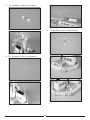
Unpacking Your Model
Your model must be removed carefully from
the packaging to avoid damage. Follow the
steps shown to remove your model.
Required Tools
Hobby knife or similar
Side cutter
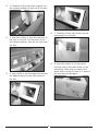
1. Use a knife to cut the tape that
secured the two center foam supports to
the inner box.
2. Carefully lift the foam support toward
the front of the boat. Lift the support
straight up and out of the box.
3. The rear support has a small piece of
foam that keeps the larger section secure.
Remove the small piece of foam.
4
4. Carefully lift the rear foam support. Lift
the support straight up and out of the box.
7. Carefully lift the main tower and its
packaging from the box.
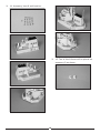
5. Use side cutters to trim the wire ties at
the rear of the hull. Lift the front of the
hull upward slightly, then lift the hull from
the box.
8. Use side cutters to cut the three
ties that secure the main tower to the
packaging. Make sure to support the
tower while cutting the ties so it doesn't
fall and become damaged.
6. Use a knife to cut the tape that secures
the packing foam for the main tower to
the box.
5
9. Remove the ties from the main tower.
12. Use side cutters to cut the ties
that secure the secondary tower and
accessories to the packaging. Make sure
to support the tower so it doesn't drop
and become damaged once the ties have
been cut.
10. Use a knife to cut the tape that
secures the foam packaging for the
secondary tower to the box.
13. Cut the remaining ties to release
the helicopter and cover from the
foam packaging.
11. Carefully lift the secondary tower and
its packaging from the box.
6
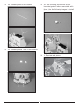
Basic Assembly
The following steps will prepare your model
for operation. Although there are a lot of
details that can be installed, they are not
necessary to operate you model.
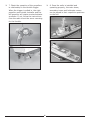
2. Plug the lead from the speed control
into the throttle port of the receiver.
The lead from the rudder servo will plug
into the steering port of the receiver. Be
sure to connect the plugs in the proper
polarity. See the radio instruction manual
for details.
Required Tools and Adhesives
Hobby knife or similar
Side cutter
Medium CA
Required Equipment and Accessories
Transmitter and receiver
Motor battery (charged)
Ballast weight (5 lb or 2.2 kg)
Hook and loop tape
1. Locate the pieces for the boat stand.
The longer side pieces will key to the
shorter end pieces. Use a small amount of
Medium CA to glue the pieces together.
3. Use hook and loop tape to attach the
receiver to the steering servo mounting
plate inside the hull. Route the antenna
wires inside the hull according to the
radio manufacturer's suggestions.
Note: If you are using a 2.4GHz system,
it is recommended to bind the receiver
to the transmitter at this time. Follow
the instructions provided with your radio
system for this procedure.
4. Place the ballast weight in the ballast
compartment in the hull. We used $8.50
in pennies in our model, but a lead weight
can also be used.
Note: Make sure to center the trims
for both the steering and throttle on
your transmitter.
7
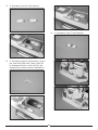
5. Place the motor battery in the hull.
The supports are cut to fit a 6-cell battery
snug in the hull.
7. Check the operation of the rudders in
relationship to the steering wheel. When
the wheel is rotated clockwise, the rudders
must move right as shown. If not, follow
the instructions from the radio to set the
servo reversing for the steering.
6. Move the switch on the transmitter to
the ON position. Connect the battery to
the lead from the speed control.
8
7. Check the operation of the propellers
in relationship to the throttle trigger.
When the trigger is pulled in, the right
propeller must rotate clockwise and the
left propeller will rotate counterclockwise
as shown. If not, follow the instructions
from the radio to set the servo reversing
for the throttle.
8. Once the radio is installed and
operating properly, the main tower,
secondary tower and helicopter covers
can be placed in their respective positions
on the hull.
9
Accessory Installation
The installation of the accessories is not
mandatory, but will add some incredibly scale
appeal to your model. There are a lot of
items to install, so take your time and take
frequent breaks to avoid frustration when
working with all the small parts.
2. Accessory item B and location.
Attaching an accessory to the hull simply
requires placing a small drop of medium CA
on the part, then placing it in the correct
location on the hull after removing the
locating sticker. The following will help
guide where each accessory is located in
alphabetical order. Use this section of the
manual, as well as the photos on the box, to
install the accessories.
Required Tools and Adhesives
Hobby knife or similar
Medium CA
Pin vise
Drill bit: 5/64-inch (2mm)
Required Equipment and Accessories
Hull, main tower, secondary tower
3. Accessory item C and location.
1. Accessory item A and location.
10
4. Accessory item D and location.
6. Accessory item F and location.
5. Accessory item E and location. Use a
pin vise and 5/64-inch (2mm) drill bit
to enlarge the hole in the hull for the
accessory as shown before installation.
11
7. Accessory item G and location.
8. Accessory item H and location.
12
9. Accessory item I and location.
10. Accessory item J and location.
13
11. Accessory item K and location.
13. Accessory item M and location.
12. Accessory item L and location.
14
14. Accessory item N and location.
15. Two of the N items will be placed on
accessory R as shown.
15
16. Accessory item O and location.
17. Accessory item P, Q and R
and locations.
16
18. Accessory item S and location.
20. The following accessories do not
have designation letters associated with
them. Use the following images to install
these items.
19. Accessory items T and Y and location.
1. Step text and photo.
17
Warranty and Repair Policy
Age Recommendation
(c) Purchaser Remedy- Horizon's sole
obligation hereunder shall be that Horizon
will, at its option, (i) repair or (ii) replace,
any Product determined by Horizon to be
defective. In the event of a defect, these are
the Purchaser's exclusive remedies. Horizon
reserves the right to inspect any and all
equipment involved in a warranty claim.
Repair or replacement decisions are at the
sole discretion of Horizon. This warranty
does not cover cosmetic damage or damage
due to acts of God, accident, misuse, abuse,
negligence, commercial use, or modification
of or to any part of the Product. This
warranty does not cover damage due to
improper installation, operation, maintenance,
or attempted repair by anyone other than
Horizon. Return of any goods by Purchaser
must be approved in writing by Horizon
before shipment.
14 years or over. This is not a toy. This
product is not intended for use by children
without direct adult supervision.
Warranty Period
Exclusive Warranty- Horizon Hobby, Inc.,
(Horizon) warranties that the Products
purchased (the "Product") will be free from
defects in materials and workmanship at the
date of purchase by the Purchaser.
Limited Warranty
Horizon reserves the right to change or
modify this warranty without notice and
disclaims all other warranties, express
or implied.
(a) This warranty is limited to the original
Purchaser ("Purchaser") and is not
transferable. REPAIR OR REPLACEMENT AS
PROVIDED UNDER THIS WARRANTY IS THE
EXCLUSIVE REMEDY OF THE PURCHASER.
This warranty covers only those Products
purchased from an authorized Horizon dealer.
Third party transactions are not covered by
this warranty. Proof of purchase is required
for warranty claims.
Damage Limits
HORIZON SHALL NOT BE LIABLE FOR
SPECIAL, INDIRECT OR CONSEQUENTIAL
DAMAGES, LOSS OF PROFITS OR
PRODUCTION OR COMMERCIAL LOSS IN
ANY WAY CONNECTED WITH THE PRODUCT,
WHETHER SUCH CLAIM IS BASED IN
CONTRACT, WARRANTY, NEGLIGENCE, OR
STRICT LIABILITY. Further, in no event shall
the liability of Horizon exceed the individual
price of the Product on which liability is
asserted. As Horizon has no control over use,
setup, final assembly, modification or misuse,
no liability shall be assumed nor accepted for
any resulting damage or injury. By the act of
use, setup or assembly, the user accepts all
resulting liability.
(b) Limitations- HORIZON MAKES NO
WARRANTY OR REPRESENTATION, EXPRESS
OR IMPLIED, ABOUT NON-INFRINGEMENT,
MERCHANTABILITY OR FITNESS FOR A
PARTICULAR PURPOSE OF THE PRODUCT.
THE PURCHASER ACKNOWLEDGES THAT
THEY ALONE HAVE DETERMINED THAT
THE PRODUCT WILL SUITABLY MEET THE
REQUIREMENTS OF THE PURCHASER’S
INTENDED USE.
If you as the Purchaser or user are not
prepared to accept the liability associated
with the use of this Product, you are advised
to return this Product immediately in new and
unused condition to the place of purchase.
Law: These Terms are governed by Illinois law
(without regard to conflict of law principals).
18
Warranty Services
Questions, Assistance, and Repairs
Warranty Inspection and Repairs
Your local hobby store and/or place of
purchase cannot provide warranty support
or repair. Once assembly, setup or use of
the Product has been started, you must
contact Horizon directly. This will enable
Horizon to better answer your questions and
service you in the event that you may need
any assistance. For questions or assistance,
please direct your email to productsupport@
horizonhobby.com, or call 877.504.0233 toll
free to speak to a service technician.
To receive warranty service, you must include
your original sales receipt verifying the
proof-of-purchase date. Provided warranty
conditions have been met, your Product will
be repaired or replaced free of charge. Repair
or replacement decisions are at the sole
discretion of Horizon Hobby.
Non-Warranty Repairs
Should your repair not be covered by
warranty the repair will be completed and
payment will be required without notification
or estimate of the expense unless the
expense exceeds 50% of the retail purchase
cost. By submitting the item for repair
you are agreeing to payment of the repair
without notification. Repair estimates are
available upon request. You must include
this request with your repair. Non-warranty
repair estimates will be billed a minimum
of ½ hour of labor. In addition you will be
billed for return freight. Please advise us of
your preferred method of payment. Horizon
accepts money orders and cashiers checks,
as well as Visa, MasterCard, American
Express, and Discover cards. If you choose
to pay by credit card, please include your
credit card number and expiration date.
Any repair left unpaid or unclaimed after
90 days will be considered abandoned and
will be disposed of accordingly. Please note:
non-warranty repair is only available on
electronics and model engines.
Inspection or Repairs
If this Product needs to be inspected or
repaired, please call for a Return Merchandise
Authorization (RMA). Pack the Product
securely using a shipping carton. Please
note that original boxes may be included,
but are not designed to withstand the rigors
of shipping without additional protection.
Ship via a carrier that provides tracking and
insurance for lost or damaged parcels, as
Horizon is not responsible for merchandise
until it arrives and is accepted at our facility.
A Service Repair Request is available at www.
horizonhobby.com on the “Support” tab.
If you do not have internet access, please
include a letter with your complete name,
street address, email address and phone
number where you can be reached during
business days, your RMA number, a list
of the included items, method of payment
for any non-warranty expenses and a brief
summary of the problem. Your original sales
receipt must also be included for warranty
consideration. Be sure your name, address,
and RMA number are clearly written on the
outside of the shipping carton.
19
Warranty Services
United States
Germany
Electronics and engines requiring inspection
or repair should be shipped to the following
address:
Electronics and engines requiring inspection
or repair should be shipped to the following
address:
Horizon Service Center
4105 Fieldstone Road
Champaign, Illinois 61822
USA
Horizon Technischer Service
Hamburger Strasse 10
25335 Elmshorn
Germany
All other Products requiring warranty
inspection or repair should be shipped to the
following address:
Please call +49 4121 46199 66 or e-mail
us at [email protected] with any
questions or concerns regarding this product
or warranty.
Horizon Product Support
4105 Fieldstone Road
Champaign, Illinois 61822
USA
France
Horizon Hobby SAS
14 Rue Gustave Eiffel
Zone d’Activité du
Réveil Matin
91230 Montgeron
Please call 877-504-0233 or e-mail us at
[email protected] with any
questions or concerns regarding this product
or warranty.
Please call +33 (0) 1 60 47 44 70 with any
questions or concerns regarding this product
or warranty.
United Kingdom
Electronics and engines requiring inspection
or repair should be shipped to the following
address:
Horizon Hobby UK
Units 1-4 Ployters Rd
Staple Tye
Harlow, Essex
CM18 7NS
United Kingdom
Please call +44 (0) 1279 641 097 or e-mail
us at [email protected] with any
questions or concerns regarding this product
or warranty.
20
Compliance Information for the European Union
Declaration of Conformity
Instructions for Disposal
of WEEE by Users in the
European Union
(in accordance with
ISO/IEC 17050-1)
This product must not be disposed
of with other waste. Instead, it is
the user’s responsibility to dispose of
their waste equipment by handing it over to
a designated collection point for the recycling
of waste electrical and electronic equipment.
The separate collection and recycling of your
waste equipment at the time of disposal
will help to conserve natural resources and
ensure that it is recycled in a manner that
protects human health and the environment.
For more information about where you can
drop off your waste equipment for recycling,
please contact your local city office, your
household waste disposal service or where
you purchased the product.
No. HH20100304
Product(s):Arleigh Burke-Class
Destroyer EP PNP
Item Number(s): PRB3375
The object of declaration described above
is in conformity with the requirements of
the specifications listed below, following the
provisions of the European EMC Directive
2004/108/EC:
EN55022Radio disturbance characteristics
EN55024
Immunity characteristics
Signed for and on behalf of:
Horizon Hobby, Inc.
Champaign, IL USA
March 04, 2010
Steven A. Hall
Vice President
International Operations and Risk
Management
Horizon Hobby, Inc.
21
®
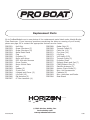
Replacement Parts
Go to ProBoatModels.com to see photos of the replacement parts listed under Arleigh BurkeClass Destroyer. If you have any questions concerning the setup or running of your model,
please see page 20 to contact the appropriate Horizon service center.
PRB3351
PRB3352
PRB3353
PRB3354
PRB3355
PRB3356
PRB3357
PRB3358
PRB3359
PRB3360
PRB3361
PRB3362
PRB3363
PRB3364
PRB3365
PRB3366
PRB3367
Printed 02/2010
Hull Only
Super Structure (F)
Super Structure (R)
Metal Detail Parts
Flag
Propeller (2)
Motor with wires
ESC 40A with Reverse
Drive Coupler
Motor Mount Plate
Heli
Rudder (2)
5-inch Gun
Lifeboat and Crane (2)
Life Raft (15)
EW Antenna (2)
6 Tube Launcher (4)
PRB3368
PRB3369
PRB3370
PRB3371
PRB3372
PRB3373
PRB3374
PRB3376
PRB3377
PRB3378
PRB3379
PRB3380
PRB3381
PRB3382
PRB3383
PRB3384
© 2010 Horizon Hobby, Inc.
horizonhobby.com
www.proboatmodels.com
Radar Dish (3)
Torpedo Tubes (2)
Cleet Set (13)
Fire Hose (14)
Life Ring
VLS Hatch (F/R)
Torpedo Crane (2)
Propeller Shaft
Exhaust Stack and Port(7)
CIWS/Plalanx Gun (2)
Satellite Antenna (2)
Anchor Chain Guide (2)
Misc. Hull Accessories
Cabinets (6)
Misc. Antennas and Radar
Boat Stand
17956