1
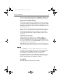
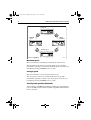
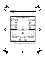
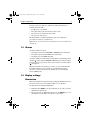
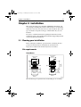
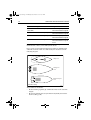
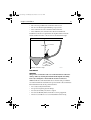
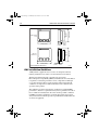
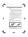
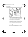
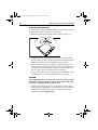
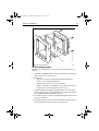
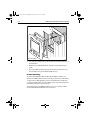
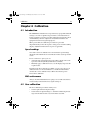
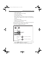
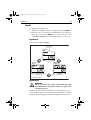
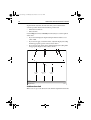
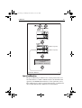
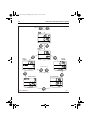
81040_1.book Page 1 Thursday, November 7, 2002 10:21 AM
ST60 Tridata
Instrument
Owner’s
Handbook
Document number: 81040-4
Date:10 November 2002
81040_1.book Page 2 Thursday, November 7, 2002 10:21 AM
Raymarine, ST60 and SeaTalk are trademarks of Raymarine Limited
© Handbook contents copyright Raymarine Limited 2002
81040_1.book Page i Thursday, November 7, 2002 10:21 AM
i
Important information
Safety notices
WARNING: Product installation & operation
This equipment must be installed and operated in accordance with
the Raymarine instructions provided. Failure to do so could result in
personal injury, damage to your boat and/or poor product
performance.
WARNING: Electrical safety
Make sure you have switched off the power supply before you start
installing this product.
WARNING:
Although we have designed this product to be accurate and reliable,
many factors can affect its performance. Therefore, it should serve
only as an aid to navigation and should never replace commonsense
and navigational judgement. Always maintain a permanent watch
so you can respond to situations as they develop.
EMC conformance
All Raymarine equipment and accessories are designed to the best
industry standards for use in the recreational marine environment.
The design and manufacture of Raymarine equipment and accessories
conform to the appropriate Electromagnetic Compatibility (EMC)
standards, but correct installation is required to ensure that performance
is not compromised.
Handbook information
To the best of our knowledge, the information in this handbook was
correct when it went to press. However, Raymarine cannot accept
liability for any inaccuracies or omissions it may contain.
In addition, our policy of continuous product improvement may change
specifications without notice. Therefore, Raymarine cannot accept
liability for any differences between the product and the handbook.
81040_1.book Page ii Thursday, November 7, 2002 10:21 AM
ii
ST60 Tridata Instrument Owner’s Manual
81040_1.book Page iii Thursday, November 7, 2002 10:21 AM
iii
Contents
Important information ..........................................................................................i
Safety notices ................................................................................. i
EMC conformance ........................................................................ i
Handbook information .................................................................. i
Introduction ......................................................................................................... vii
Data inputs ..................................................................................vii
SeaTalk .......................................................................................vii
Stand alone operation .................................................................viii
Remote control ..........................................................................viii
Mounting options .......................................................................viii
Parts supplied ............................................................................... ix
Chapter 1:
Operation .........................................................................................1
1.1 Getting started ............................................................................... 1
Displayed information .................................................................. 1
1.2 Normal operation .......................................................................... 1
Depth ............................................................................................ 2
Current depth display .............................................................. 2
Depth alarm threshold displays ............................................... 3
Speed ............................................................................................ 3
Boat speed ............................................................................... 3
Maximum speed ..................................................................... 4
Average speed ......................................................................... 4
Velocity made good (to windward) ......................................... 4
Trip ................................................................................................ 5
Log .......................................................................................... 5
Trip screen ............................................................................... 6
Water temperature ................................................................... 6
Timers ..................................................................................... 6
1.3 Alarms .......................................................................................... 7
1.4 Display settings ............................................................................. 7
Illumination .................................................................................. 7
Contrast ......................................................................................... 8
1.5 Remote control ............................................................................. 8
Chapter 2:
Maintenance and Faultfinding ......................................................9
2.1 Maintenance ................................................................................. 9
Servicing and safety ...................................................................... 9
Instrument ..................................................................................... 9
Transducers ................................................................................... 9
Cabling ........................................................................................ 10
81040_1.book Page iv Thursday, November 7, 2002 10:21 AM
iv
ST60 Tridata Instrument Owner’s Manual
2.2
Fault finding ................................................................................ 10
Preliminary procedures ............................................................... 10
Fixing faults ................................................................................ 10
Technical support ........................................................................ 11
World wide web .................................................................... 11
Telephone help line ............................................................... 11
Help us to help you ................................................................ 12
Chapter 3:
Installation .....................................................................................13
3.1 Planning your installation ........................................................... 13
Site requirements ........................................................................ 13
Transducers ........................................................................... 13
Instrument ............................................................................. 15
EMC Installation Guidelines ...................................................... 16
Suppression Ferrites .............................................................. 17
Connections to Other Equipment .......................................... 17
3.2 Procedures .................................................................................. 18
Unpacking ................................................................................... 18
Fitting the instrument .................................................................. 18
Surface mounting .................................................................. 18
Flush mounting ..................................................................... 19
Bracket mounting .................................................................. 22
Fitting transducer ........................................................................ 23
Running transducer cable ...................................................... 23
Connecting the instrument .......................................................... 24
Types of connection .............................................................. 24
Signal connections ................................................................ 24
Power supply connections .................................................... 25
Chapter 4:
Calibration .....................................................................................27
4.1 Introduction ................................................................................ 27
Speed readings ............................................................................ 27
EMC conformance ...................................................................... 27
4.2 User calibration ........................................................................... 27
Depth ........................................................................................... 29
Depth units ............................................................................ 29
Depth offset ........................................................................... 29
Shallow alarm lock ............................................................... 30
Speed ........................................................................................... 31
Set speed units ....................................................................... 31
Set speed resolution .............................................................. 31
Set log units ........................................................................... 31
Setting the correct speed ....................................................... 31
Adjust to SOG ....................................................................... 33
81040_1.book Page v Thursday, November 7, 2002 10:21 AM
v
4.3
4.4
Set temperature units ............................................................ 33
Temperature calibration ........................................................ 33
Timer alarm buzzer ............................................................... 33
Leaving User calibration ............................................................. 33
Intermediate calibration .............................................................. 34
Speed calibration ........................................................................ 35
Leaving Intermediate calibration ................................................ 39
Dealer calibration ....................................................................... 39
User calibration on/off ................................................................ 39
Response settings ........................................................................ 39
Boat show mode .......................................................................... 41
Factory defaults .......................................................................... 41
Leaving Dealer calibration ......................................................... 41
81040_1.book Page vi Thursday, November 7, 2002 10:21 AM
vi
ST60 Tridata Instrument Owner’s Manual
81040_1.book Page vii Thursday, November 7, 2002 10:21 AM
vii
Introduction
Thank you for purchasing a Raymarine product. We are sure your ST60
instrument will give you many years of trouble-free operation.
This handbook describes how to install and use the Raymarine ST60
Tridata instrument. This instrument provides accurate depth, speed, trip
and timer information, on a high quality Liquid Crystal Display (LCD).
The instrument is constructed in a rugged weather-proofed case to provide reliable performance, even under the most demanding conditions.
D4324-1
Data inputs
The ST60 Tridata instrument can fulfil master and/or repeater roles by
receiving data either from the appropriate transducers and/or from a
SeaTalk instrumentation system.
SeaTalk
SeaTalk enables a number of compatible instruments to operate as a
single, integrated navigational system. Instruments in a SeaTalk system
are linked by means of a single cable, which feeds both power and data.
Instruments can therefore be added to the system by plugging them into
the network. SeaTalk is flexible enough to adapt to any number of
compatible instruments without requiring a central processor. SeaTalk
can also communicate via an interface, with non-SeaTalk equipment
using the internationally-accepted National Marine Electronics
Association (NMEA) protocol.
81040_1.book Page viii Thursday, November 7, 2002 10:21 AM
viii
ST60 Tridata Instrument Owner’s Manual
In a SeaTalk system, each instrument can be either a master or dedicated
repeater unit. A master instrument is directly connected to a transducer
(the device that provides the raw data), and provides data and control for
the service it is providing, to all other equipment on the SeaTalk network.
A slave instrument is not directly connected to a transducer but repeats
information provided by other equipment in the SeaTalk network.
Stand alone operation
In Stand alone operation, the ST60 Tridata instrument is connected only
to the relevant transducer and does not display information from, or
provide information to, any other instruments.
Remote control
When connected to SeaTalk, the ST60 Tridata instrument can be
controlled remotely by a SeaTalk Remote Keypad Unit, to provide
instant remote access to the various display readouts.
Mounting options
If you do not want to surface mount your ST60 instrument, options are
available for:
• Flush mounting. If you have ordered the flush mounting option a lowprofile bezel and four fixing screws are also provided.
• Bracket mounting.
81040_1.book Page ix Thursday, November 7, 2002 10:21 AM
ix
Parts supplied
Unpack your ST60 instrument and check that the following items are
present:
• Item 1, ST60 Tridata instrument fitted with standard bezel for
surface mounting.
• Item 2, Fixing studs (2).
• Item 3, Thumb nuts (2).
• Item 4, Gasket.
• Item 5, Depth transducer.
• Item 6, Speed transducer, plus bung (not illustrated).
• Item 7, SeaTalk interconnection cable.
• Item 8, Power cable.
• Item 9, Instrument Cover.
• Item 10, Owner’s Handbook. A Warranty document and fitting
templates are included in this Handbook.
• Item 11, Cue Card.
Spare spade terminals are also provided, to re-terminate the transducer
cable if it has to be cut to facilitate installation.
Note: The above packing list is for an ST60 Tridata system. Where an
instrument is purchased separately, Speed and Depth transducers are
not included.
81040_1.book Page x Thursday, November 7, 2002 10:21 AM
x
ST60 Tridata Instrument Owner’s Manual
1
2
4
3
6
2
3
5
7
9
8
TRIDATA
ST60
Tridata
Instrument
Owner's
Handbook
Current
depth
trip
speed
depth
Boat speed
Log
Trip
Shallow Alarm
Threshold
Maximum
speed
reset
3s to Reset
Water
temperature
reset
3s to Reset
Deep
alarm threshold
Average speed
Count-up timer
reset
VMG to
windward
3s to Reset
Anchor shallow
alarm threshold
reset
3s to Reset
reset
reset
Start/Stop
3s to Reset
5 minute
race start timer
Anchor deep
alarm threshold
10
reset
Start/Stop
10 minute
race start time
reset
reset
Start/Stop
3s to Reset
11
D4441-4
81040_1.book Page 1 Thursday, November 7, 2002 10:21 AM
Chapter 1: Operation
1
Chapter 1: Operation
1.1 Getting started
This handbook describes how to operate, maintain and install the
Raymarine ST60 Tridata instrument.
CAUTION:Calibration requirement
The ST60 Tridata instrument is calibrated to factory (default)
settings when first installed and must therefore be calibrated before
use, in accordance with the procedures in Chapter 4, Calibration, to
ensure optimum performance on your vessel.
Do NOT use the instrument until the calibration procedures have
been satisfactorily completed.
Displayed information
The ST60 Tridata instrument screen is divided into three separate areas,
each of which displays a separate type of information, as shown in the
following illustration.
Depth
Speed
Trip, log, water
temperature & timer
Screen layout
D4424-2
1.2 Normal operation
Use the flow charts in this Chapter to operate your ST60 Tridata
instrument. Flow charts are provided for:
• Using the depth key. This gives access to current depth information.
On master instruments, this also gives access to depth alarm threshold
information, and allows you to set the alarm thresholds.
• Using the speed key. This gives access to maximum speed, average
speed and Velocity Made Good (VMG) to windward.
81040_1.book Page 2 Thursday, November 7, 2002 10:21 AM
2
ST60 Tridata Instrument Owner’s Manual
•
Using the trip key to gain access to log, trip, water temperature and
timer information.
All key presses are momentary unless otherwise stated.
Depth
Use the depth key to select the required information, as shown in the
Using the depth key illustration. The depth measurement units are either
feet or metres, as selected during user calibration (see Chapter 4,
Calibration).
Current depth
depth
depth
To enable/disable any alarm
Shallow
alarm threshold
Press reset for 2 seconds
(toggle action)
Anchor deep
alarm threshold
To enter and exit alarm adjust mode
Press
trip
and reset together
depth
depth
In adjust mode, use
Deep
alarm threshold
trip
to decrease or reset to increase
Anchor shallow
alarm threshold
depth
Using the depth key
D4413-1
Current depth display
The current depth screen shows the title DEPTH, the selected depth units
and the depth measurement. It also shows a depth trend indicator, which
is either an up arrow to show seabed rising or a down arrow to show
seabed falling.
81040_1.book Page 3 Thursday, November 7, 2002 10:21 AM
Chapter 1: Operation
3
If for any reason depth information is lost, the DEPTH title will flash once
per second and the displayed depth value will be the last good reading.
Depth alarm threshold displays
The alarm threshold displays are available if the instrument is operating
as a master. Each display is identified by the presence of an alarm symbol
( )and either an up arrow for a shallow alarm or a down arrow for a deep
alarm. The shallow and deep anchor alarms are identified by means of an
additional anchor icon.
You can enable and disable individual alarm thresholds by pressing the
reset key for 2 seconds, while the relevant alarm threshold is displayed.
Each alarm threshold is displayed for a nominal 7 seconds, and if no
action is taken during that time, the display will timeout to the current
depth display.
Adjusting alarm thresholds
To adjust the alarm threshold levels, press the trip and reset keys
simultaneously to enter adjust mode, then use either the trip key (to
decrease) or the reset key (to increase) the threshold value. When you
have set the required value, press the trip and reset keys again, to save the
alarm setting and exit the adjust mode.
Note: Adjustment of the shallow alarm threshold can be disabled during
calibration. When adjustment is disabled, you cannot enter adjust mode.
Speed
Use the speed key to select the required information, as shown in the
Using the speed key illustration. The speed measurement units are either
knots (KTS), miles per hour (MPH) or kilometres per hour (KMH), as
selected during user calibration (see Chapter 4, Calibration).
The maximum speed, average speed and VMG to windward are each
displayed for a nominal 7 seconds, and if no action is taken during that
time, the display will timeout to the Boat speed display.
Boat speed
Shows the current speed and selected speed units.
81040_1.book Page 4 Thursday, November 7, 2002 10:21 AM
4
ST60 Tridata Instrument Owner’s Manual
Boat speed
speed
speed
VMG to
windward
Maximum
speed
speed
Average speed
speed
Using the speed key
D4414-1
Maximum speed
The screen shows the maximum speed attained since the last reset.
The maximum speed value is reset automatically at power-up. If the
instrument is operating as a master, the maximum speed can also be reset
manually by pressing the reset key for 2 seconds.
Average speed
The screen shows the average speed since the last reset.
The average speed value is reset automatically at power-up. If the
instrument is operating as a master, the average speed can also be reset
manually by pressing the reset key for 2 seconds.
Velocity made good (to windward)
Velocity made good (VMG) information is available if your instrument is
part of a SeaTalk system to which a SeaTalk-compatible wind instrument
is also connected.
81040_1.book Page 5 Thursday, November 7, 2002 10:21 AM
Chapter 1: Operation
5
Trip
The trip key gives access to log, trip, water temperature and timer
displays, as shown in the Using the trip key illustration.
trip
Water
temperature
Trip
trip
trip
Count-up
timer
Log
trip
trip
Race start
timer 1
Race start
timer 2
Press
reset
either momentarily
to start timer, or for lap time (when running)
or for 1 s to reset timer to start value.
trip
To enter/leave
adjust mode, press
trip
To enter/leave
adjust mode, press
trip
and reset
and reset
momentarily
momentarily
To set a different race start timer value, press
Using the trip key
trip
reset
to decrease the value
to increase the value
D4415-2
Log
The Log screen shows the total distance covered by the vessel since the
instrument was fitted.
81040_1.book Page 6 Thursday, November 7, 2002 10:21 AM
6
ST60 Tridata Instrument Owner’s Manual
Trip screen
The trip screen shows the distance covered since the trip value was last
reset.
The trip value is reset automatically at power-up, and if the instrument is
operating as a master, the trip value can also be reset manually by
pressing the reset key for 3 seconds.
Water temperature
The water temperature is shown in either degrees Celsius (°C) or
Fahrenheit (°F), as set during calibration (see Chapter 4, Calibration).
Timers
The count-up timer and to the two race-start timer times are either in
seconds (S) or minutes (M), depending on the counter values.
Refer to the Using the trip key flow diagram to display the required timer.
Once you have done this, press the reset key to start the timer running.
When a timer is running, the delimiter (i.e. ‘.’or ‘:’) flashes. For lap
timing, press the reset key. To stop and reset a timer to the start value,
hold down the reset key for 1 second.
Once a timer is running, you can leave the timer page and select any other
display. The counter will continue to run in the background.
Race-start timers
You can set each race-start timer to any whole-minute value from 1 to 15
minutes.
Note: When the instrument is first installed, the race-start timers are set
to 4 and 5 minutes respectively.
To set a race-start timer:
1. Use the trip key as shown in the Using trip key flow diagram to select
the required race-start timer.
2. Simultaneously press the trip and reset keys to enter the race-start
timer adjust mode.
3. Use either the trip or reset key to set the required value.
4. Simultaneously press the trip and reset keys to save the value and
leave the race-start timer adjust mode.
81040_1.book Page 7 Thursday, November 7, 2002 10:21 AM
Chapter 1: Operation
7
If you are using one of the race-start timers and the timer buzzer is
enabled, the buzzer will:
• Double-beep every minute.
• Beep three times at the start of the last 30 seconds.
• Beep once for each of the last 10 seconds.
• Beep for 2 seconds at zero.
The timer buzzer is enabled or disabled as part of the calibration
procedure (see Chapter 4, Calibration).
Note: After a race-start timer has counted-down to zero, it will then start
counting up.
1.3 Alarms
An alarm condition occurs if:
• The depth is less than the SHALLOW or SHALLOW anchor threshold.
• The depth is greater than the DEEP anchor threshold.
• The depth crosses the DEEP threshold.
An alarm condition is indicated by an alarm buzzer and a flashing alarm
symbol ( ) on the display. SHALLOW or DEEP alarms are indicated by up
and down arrows respectively, and for anchor alarms an anchor symbol
( ) is displayed.
When the instrument is operating as a master, you can check the alarm
thresholds and if necessary set them up, as detailed under Normal
operation - Depth. If an alarm is not enabled, the associated display
shows an OFF legend.
1.4 Display settings
Illumination
When the instrument is first powered up, the display illumination is set to
its lowest (courtesy) level, to facilitate initial access to the keys.
To adjust the level of display illumination:
1. Hold down the depth key for approximately one second, to enter the
illumination-adjust mode.
2. There are four preset illumination levels. Use the depth key to cycle
through these levels until you reach the level you want.
81040_1.book Page 8 Thursday, November 7, 2002 10:21 AM
8
ST60 Tridata Instrument Owner’s Manual
3. Press any other key to leave the illumination-adjust mode.
Note: The display will also return to normal operation 7 seconds after
the last key press.
Contrast
To adjust the display contrast:
1. Hold down the depth key for approximately two seconds, to enter the
contrast-adjust mode.
2. There are four preset contrast settings. Use the depth key to cycle
through these settings until you achieve optimum display quality.
3. Press any other key to leave the contrast-adjust mode.
Note: The display will also return to normal operation 7 seconds after
the last key press.
1.5 Remote control
When it is connected to SeaTalk, the ST60 Tridata instrument can be
controlled remotely with a SeaTalk Remote Keypad Unit. Remote
control of an instrument is indicated by a REMOTE legend on the display,
to indicate that the keypad has control.
Details on how to use the remote control facility can be found in the
SeaTalk Remote Keypad Owner’s Handbook.
81040_1.book Page 9 Thursday, November 7, 2002 10:21 AM
Chapter 2: Maintenance and Faultfinding
9
Chapter 2: Maintenance and Faultfinding
2.1 Maintenance
Servicing and safety
•
•
•
•
•
Raymarine equipment should be serviced only by authorised Raymarine service technicians. They will ensure that servicing procedures
and replacement parts used will not affect performance. There are no
user-serviceable parts in any Raymarine product.
Some products generate high voltages, and so never handle the
cables/connectors when power is being applied to the equipment.
When powered up, all electrical equipment produces electromagnetic fields. These can cause adjacent pieces of electrical equipment
to interact with one another, with a consequent adverse effect on operation. In order to minimise these effects and enable you to get the best
possible performance from your Raymarine equipment, guidelines
are given in the installation instructions, to enable you to ensure minimum interaction between different items of equipment, i.e. ensure
optimum Electromagnetic Compatibility (EMC).
Always report any EMC-related problem to your nearest Raymarine
dealer. We use such information to improve our quality standards.
In some installations, it may not be possible to prevent the equipment
from being affected by external influences. In general this will not
damage the equipment but it can lead to spurious resetting action, or
momentarily may result in faulty operation.
Instrument
Certain atmospheric conditions may cause condensation to form on the
instrument window. This will not harm the instrument and can be cleared
by increasing the illumination setting to Level 3.
Periodically clean your ST60 instrument with a soft damp cloth. Do NOT
use chemical and abrasive materials to clean the instrument.
Transducers
Refer to the Installation and Maintenance instructions supplied with the
transducers.
81040_1.book Page 10 Thursday, November 7, 2002 10:21 AM
10
ST60 Tridata Instrument Owner’s Manual
Cabling
Examine all cables for chafing or other damage to the outer shield and,
where necessary, replace and re-secure.
2.2 Fault finding
Preliminary procedures
Changes in the electronic environment may adversely affect the operation of your ST60 equipment. Typical examples of such changes are:
• Electrical equipment has recently been installed or moved aboard
your vessel.
• You are in the vicinity of another vessel or shore station emitting radio
signals.
If you appear to have a problem, first ensure that the EMC requirements
(see Chapter 3, Installation) are still being met before further
investigating the problem.
Fixing faults
All Raymarine products are subjected to comprehensive test and quality
assurance programmes prior to packing and shipping. However, if a fault
occurs, the following table may help to identify and rectify the problem.
Fault
Cause
Remedy
Instrument display blank. No power supply.
Check power supply.
Check SeaTalk cabling and connector
security.
Check fuse/circuit breaker.
No speed or temperature
information.
Speed transducer
cabling problem.
Check cabling and security of
transducer connections.
No speed information.
Clean paddle wheel.
Speed transducer
paddle wheel fouled See CAUTION below.
No exchange of information between SeaTalk
instruments
SeaTalk cabling
problem.
Check the security of SeaTalk
connectors.
Disconnect instruments one by one, to
isolate faulty unit
81040_1.book Page 11 Thursday, November 7, 2002 10:21 AM
Chapter 2: Maintenance and Faultfinding
11
Fault
Cause
Remedy
Failure of group of
instruments in SeaTalk
chain.
SeaTalk cabling or
connector problem.
Check the security of SeaTalk
connections between functioning and
non-functioning instruments.
LAST flashes or dashes
Depth transducer or Check depth transducer cable and
displayed continuously
connection problem. security of transducer connections.
(depth greater than 3 feet).
LAST flashes while under
way.
Aerated water
Boat wake
Prop wash etc
Ensure readings stabilise when clear of
disturbed water.
CAUTION:
If you need to remove the Speed transducer insert, have the
transducer bung to hand and secure it in the transducer body
immediately after the insert has been removed, to prevent excessive
ingress of water.
Technical support
Raymarine provides a comprehensive customer support service, on the
world wide web and by telephone help line. Please use either of these
facilities if you are unable to rectify a problem.
World wide web
Please visit the Customer Support area of our web site at:
www.raymarine.com
As well as providing a comprehensive Frequently Asked Questions
section and servicing information, it also gives e-mail access to the
Raymarine Technical Support Department and a details of the locations
of Raymarine agents, worldwide.
Telephone help line
If you do not have access to the world wide web, please call:
1-800-539-5539, extension 2444 or
(603) 881-5200 extension 2444
81040_1.book Page 12 Thursday, November 7, 2002 10:21 AM
12
ST60 Tridata Instrument Owner’s Manual
Help us to help you
When requesting service, please quote the following product
information:
• Equipment type.
• Model number.
• Serial number.
• Software issue number.
The Software issue number can be ascertained by means of the
Intermediate Calibration facility, see Chapter 4, Calibration.
81040_1.book Page 13 Thursday, November 7, 2002 10:21 AM
Chapter 3: Installation
13
Chapter 3: Installation
This chapter describes how to install the ST60 Tridata instrument, and
associated Speed and Depth transducers. The transducers are fitted in the
hull of the vessel and connected to the rear of the instrument. The actual
type of transducers depends on the type of hull in which they are to be
installed.
For advice, or further information regarding the installation of this
equipment, please contact the Raymarine Product Support Department
or your own National Distributor.
3.1 Planning your installation
Before starting the installation, spend some time considering the best
positions for both transducer and instrument, such that the Site
Requirements and the EMC Guidelines (below) are satisfied.
Site requirements
Transducers
95 mm (3.75 in)
Depth
51 mm (2.0 in)
diameter
75 mm (2.94 in)
diameter
5 mm
(0.19 in)
100 mm
(3.95 in)
75 mm (2.94 in)
diameter
75 mm (2.94 in)
diameter
Speed
51 mm (2.0 in)
diameter
14 mm
(0.57 in)
75 mm (2.94 in)
diameter
D4447-4
The transducer types required for the various hull types are as follows:
81040_1.book Page 14 Thursday, November 7, 2002 10:21 AM
14
ST60 Tridata Instrument Owner’s Manual
Hull material
Speed transducer
Depth transducer
Glass reinforced
plastic (GRP)
M78712 Through hull plastic
M78713 Through hull plastic or
M78718 Retractable through hull
Steel
M78712 Through hull plastic
M78713 Through hull plastic or
M78718 Retractable through hull
Aluminium
M78712 Through hull plastic
M78713 Through hull plastic or
M78718 Retractable through hull
Wood
M78716 Through hull bronze
M78714 Through hull bronze or
M78719 Retractable through hull
bronze
Other transducer types are also available for specific requirements. For
further details, contact your local Raymarine dealer.
For accurate speed and depth readings the transducers should be sited
within the clear water flow areas indicated by the shaded areas in the
following diagram.
Sailing vessel
Planing power
vessel
Displacement power
vessel
Transducer siting
D4349-1
The transducers should also:
• Be ahead of the propellers (by a minimum of 10% of the water line
length).
• Be at least 150 mm (6 in) away from the keel (ideally ahead of the
keel if a sailing yacht).
81040_1.book Page 15 Thursday, November 7, 2002 10:21 AM
Chapter 3: Installation
•
•
•
•
15
Be as near as possible to the centre line of the vessel.
Be clear of other through-hull fittings or projections.
Have sufficient clearance inside the hull to fit the nut.
Have 100 mm (4 in) of headroom to allow for withdrawal.
In addition to the above requirements, the depth transducer must be
mounted within 10 of the vertical, forward, aft and athwart ships.
0
10˚ maximum
Maximum transducer angle
D4350-3
Instrument
CAUTION:
The presence of moisture at the rear of the instrument could cause
damage either by entering the instrument through the breathing
hole or by coming into contact with the electrical connectors.
ST60 instruments can be fitted either above or below deck, provided the
rear of the instrument is sited where it is protected from contact with water.
Each instrument must also be positioned where:
• It is easily read by the helmsman
• It is protected against physical damage
• It is at least 230 mm (9 in) from a compass
• It is at least 500 mm (20 in) from radio receiving equipment
• There is reasonable rear access for installation and servicing
81040_1.book Page 16 Thursday, November 7, 2002 10:21 AM
24mm
(0.95in)
15mm
(0.6in)
90mm (3.54in)
diameter
110mm (4.33in)
With low
profile bezel
123mm (4.85in)
ST60 instrument dimensions
6.2mm
(0.25in)
123mm (4.85in)
With standard
bezel
115mm (4.53in)
ST60 Tridata Instrument Owner’s Manual
90mm (3.54in)
diameter
16
35mm
(1.4in)
D5785-1
EMC Installation Guidelines
All Raymarine equipment and accessories are designed to the best
industry standards for use in the recreational marine environment.
Their design and manufacture conforms to the appropriate
Electromagnetic Compatibility (EMC) standards, but correct installation
is required to ensure that performance is not compromised. Although
every effort has been taken to ensure that they will perform under all
conditions, it is important to understand what factors could affect the
operation of the product.
The guidelines given here describe the conditions for optimum EMC
performance, but it is recognized that it may not be possible to meet all of
these conditions in all situations. To ensure the best possible conditions
for EMC performance within the constraints imposed by any location,
always ensure the maximum separation possible between different items
of electrical equipment.
81040_1.book Page 17 Thursday, November 7, 2002 10:21 AM
Chapter 3: Installation
17
For optimum EMC performance, it is recommended that wherever
possible:
• Raymarine equipment and cables connected to it are:
• At least 3 ft (1 m) from any equipment transmitting or cables carrying radio signals e.g. VHF radios, cables and antennas. In the
case of SSB radios, the distance should be increased to 7 ft (2 m).
• More than 7 ft (2 m) from the path of a radar beam. A radar beam
can normally be assumed to spread 20 degrees above and below
the radiating element.
• The equipment is supplied from a separate battery from that used for
engine start. Voltage drops below 10 V in the power supply to our
products, and starter motor transients, can cause the equipment to
reset. This will not damage the equipment, but may cause the loss of
some information and may change the operating mode.
• Raymarine specified cables are used. Cutting and rejoining these
cables can compromise EMC performance and must be avoided
unless doing so is detailed in the installation manual.
• If a suppression ferrite is attached to a cable, this ferrite should not be
removed. If the ferrite needs to be removed during installation it must
be reassembled in the same position.
Suppression Ferrites
The following illustration shows typical cable suppression ferrites used
with Raymarine equipment. Always use the ferrites supplied by
Raymarine.
D3548-2
Connections to Other Equipment
If your Raymarine equipment is to be connected to other equipment using
a cable not supplied by Raymarine, a suppression ferrite MUST always
be attached to the cable near the Raymarine unit.
81040_1.book Page 18 Thursday, November 7, 2002 10:21 AM
18
ST60 Tridata Instrument Owner’s Manual
3.2 Procedures
As it is not possible to describe procedures for all possible installation
scenarios, the procedures given here describe the broad requirements for
installing the Speed and Depth transducers and the ST60 Tridata
instrument. Adapt these procedures as appropriate, to suit your
individual requirement.
CAUTION:
Where it is necessary to cut holes (e.g. for cable routing and
instrument mounting), ensure that these will not cause a hazard by
weakening critical parts of the vessel’s structure.
Unpacking
Unpack your ST60 equipment and check that the items described in
Introduction are present.
Each ST60 instrument is supplied with a standard bezel for surface
mounting. Optional mounting kits are available for flush mounting and
bracket mounting the instrument. If you have ordered the flush mounting
option a low-profile bezel and four fixing screws are also provided.
Fitting the instrument
The ST60 Tridata instrument can be installed using one of a number of
different mounting options:
• Surface mounting. Gives a profile of approximately 24 mm.
• Flush mounting. Gives a profile of approximately 6 mm.
• Bracket mounting.
The ST60 instruments can also be mounted behind a panel with just the
instrument dial and keys visible.
Surface mounting
To surface mount your ST60 instrument (see the Surface mounting
illustration):
1. Ensure that:
• The selected location is clean, smooth and flat.
• There is sufficient space behind the selected location to accommodate the rear of the instrument and connectors.
81040_1.book Page 19 Thursday, November 7, 2002 10:21 AM
Chapter 3: Installation
19
4
Surface mounting
1
2
1
3
5
2
5
D4343-2
2. Apply the surface mount template (supplied at the rear of this handbook) to the selected location and mark the centres for the fixing studs
(1) and the aperture (3) that will take the rear casing of the instrument.
3. Drill out the two 5 mm fixing stud clearance holes (2).
4. Cut out the clearance hole (3) then remove the template.
5. Peel off the protective sheet from the self-adhesive gasket (4) then
stick the gasket into position on the rear of the instrument.
6. Screw the two fixing studs into the threaded sockets on the rear of the
instrument.
7. Mount the assembled instrument, studs, bezel and gasket into the
panel. Secure from behind with the thumb nuts (5).
Flush mounting
The Flush Mounting Kit uses a low-profile bezel to reduce the fitted
profile of the instrument, to approximately 6 mm above the panel fascia.
81040_1.book Page 20 Thursday, November 7, 2002 10:21 AM
20
ST60 Tridata Instrument Owner’s Manual
Fitting the low-profile bezel
In order to flush-mount your ST60 instrument, you must first replace the
standard bezel with the low-profile bezel as follows:
1. Hold the instrument in both hands with the display towards you.
D4537-2
2. Using both thumbs, gently press an upper corner of the instrument
from the bezel, then remove the bezel from the instrument. Retain the
rubber keypad which is released when the bezel is removed.
3. Referring to the Fitting the low-profile bezel illustration, place the
instrument face upwards on a flat surface and place the rubber keypad
(7) in position around the display window (i.e. so that each key outline is located over its associated key on the instrument).
4. Snap the low-profile bezel (8) in position over the instrument, so that
the rubber keys are correctly located in the holes on the bezel.
CAUTION:
It is essential that only screws of the correct size are used to secure the
instrument to the bezel. Failure to observe this caution could result
in damage to both the instrument and the bezel.
5. Using the four, self-tapping screws (9) provided, secure the instrument and bezel together. Fit the screws from the rear of the instrument
and tighten them sufficiently to secure the instrument and bezel
together. DO NOT OVERTIGHTEN.
81040_1.book Page 21 Thursday, November 7, 2002 10:21 AM
Chapter 3: Installation
21
8
Fitting the low profile bezel
7
9
D4362-2
Flush mounting procedure
Flush mount your instrument (see the Flush mounting illustration) as
follows:
1. Assemble the ST60 instrument and low-profile bezel as described
under Fitting the low-profile bezel.
2. Ensure that:
• The panel on which you intend to mount the instrument is
between 3 mm and 20 mm thickness.
• The selected location is clean, smooth and flat.
• There is sufficient space behind the selected location to accommodate the rear of the instrument and connectors.
3. Apply the flush mount template (supplied at the rear of this handbook) to the selected location and mark out the aperture into which
the assembled instrument and bezel will sit.
4. Cut out the aperture (3) for the assembled instrument and bezel and
remove the template.
5. Peel off the protective sheet from the self-adhesive gasket (4) then
stick the gasket into position on the rear of the bezel.
81040_1.book Page 22 Thursday, November 7, 2002 10:21 AM
22
ST60 Tridata Instrument Owner’s Manual
1
Flush mounting
3
1
5
6
5
4
D5462-1
6. Screw the two fixing studs (1) into the threaded sockets on the rear of
the instrument.
7. Mount the assembled instrument, studs, bezel and gasket into the
panel.
8. Locate the flush mount bracket (6) onto the fixing studs and secure
the assembly to the panel with the thumb-nuts (5).
Bracket mounting
A Control Unit Mounting Bracket (Part No. E25009) enables you to
mount your ST60 instrument in locations where other forms of mounting
are impractical. Although this provides a useful alternative method for
securing your instrument, it is only suitable for use in positions where the
instrument will not be exposed to water.
To bracket mount your ST60 instrument, do so in accordance with the
Control Unit Mounting Bracket Instruction Sheet.
81040_1.book Page 23 Thursday, November 7, 2002 10:21 AM
Chapter 3: Installation
23
Fitting transducer
The ST60 Tridata instrument is supplied, with appropriate through-hull
Speed and Depth transducers.
Each transducer is supplied with detailed instructions for installation and
maintenance. Before attempting to install a transducer, read these
instructions and the Site requirements for transducers described in this
Chapter.
Once you are satisfied you can meet all the installation requirements,
install the transducer in accordance with the accompanying installation
instructions.
Running transducer cable
Each transducer type has a 14 m (45 ft) cable fitted with spade terminals
for connection to the ST60 Tridata instrument. The manner in which you
run the cable will depend on the locations of the transducers and
instrument. The following guidelines are provided:
•
•
•
•
•
•
If the cable has to be fed through the deck, always use a proprietary
deck gland.
Where cables are fed through holes, always use grommets to prevent
chafing.
Secure long cable runs so they do not present a hazard.
Do not route the cable through bilges.
Wherever possible, route the cable away from fluorescent lights,
engines, radio transmitting equipment, as these may cause interference.
The transducer cables are fitted with spade connectors for direct connection to the rear of the instrument. However, it may be necessary to
remove these to facilitate installation, e.g. if a cable has to be routed
through narrow apertures. Extra spade connectors are provided, to
replace any that are removed when running transducer cables. When
fitting spade connectors, prepare the cable as at (a) in the following
illustration, then fold back the wire strands and insert into the spade
connector as at (b). Ensure the wire strands do not extend beyond the
rear of the spade connector insulation, then crimp the connector to the
wire.
81040_1.book Page 24 Thursday, November 7, 2002 10:21 AM
24
ST60 Tridata Instrument Owner’s Manual
50 mm
6 mm
(a)
(b)
3 mm
D4467-6
Observing the above guidelines, run the transducer cables to the ST60
Tridata instrument.
Connecting the instrument
Types of connection
The ST60 Tridata instrument, can be connected:
•
•
•
As a stand-alone, master instrument connected directly to a Speed
and/or Depth transducer.
As a SeaTalk repeater.
To fulfil both repeater and master roles by being connected both to the
transducer and to SeaTalk.
If instruments are connected to SeaTalk, no separate power connection is
necessary. Where a SeaTalk system includes an autopilot, the power for
the system is provided by the autopilot.
A range of Raymarine SeaTalk extension cables is available to connect
separated instruments. These cables are supplied with a SeaTalk
connector fitted to each end. A junction box can be used to join cables.
Signal connections
Make the necessary connections to your ST60 instrument (see the
Connection to ST60 Tridata instrument illustration).
81040_1.book Page 25 Thursday, November 7, 2002 10:21 AM
Chapter 3: Installation
25
SeaTalk cable
SeaTalk cable
DE
PT
H
SPE
ED
Black
Blue
Brown
White
Screen
Green
Red
Screen
Cable from Depth transducer
Cable from Speed transducer
Connections to ST60 Tridata instrument
D4423-1
Power supply connections
SeaTalk systems
CAUTION:
When instruments are connected to SeaTalk, ensure that the power
supply for the SeaTalk 12 V line is protected by a 5 A fuse.
Systems with a large number of instruments on the SeaTalk bus may
require connections to the power supply from each end of the system
(‘ring-main’ style), to maintain sufficient voltage throughout the system.
This requirement depends on the total length of the cable run and the total
number of instruments in the system, as follows:
Cable run
No. of instruments
Power connections
Up to 10 m
13 maximum
26 maximum
1
2
Up to 20 m
7 maximum
13 maximum
1
2
81040_1.book Page 26 Thursday, November 7, 2002 10:21 AM
26
ST60 Tridata Instrument Owner’s Manual
Red
5 A fused,
12 V dc supply
(typically provided
by autopilot)
1
2
3
4
Screen
Instruments
5 to 16
Red
Screen
SeaTalk power connections
20
19
18
17
D4311-1
Stand alone instruments
Stand-alone instruments are not connected to SeaTalk and therefore need
to be connected to an alternative 12 V power source. Power cables are
available in 2 m and 9 m lengths.
To fit a power cable:
1. Ensure the intended power source is switched off. If you are using a
12 V battery, ensure the power cable is not connected to the battery.
2. Run the power cable from the instrument to a suitable 12 V dc power
source.
3. If the cable has not already been trimmed at the power supply end:
• Cut the cable to length and trim back an appropriate amount of the
outer sheath.
• Cut back and insulate the yellow wire.
4. Connect the screen to the power supply 0 V terminal.
5. Connect the red wire via a 3 A over-current circuit breaker to the
power supply +12 V terminal.
81040_1.book Page 27 Thursday, November 7, 2002 10:21 AM
Calibration
27
Chapter 4: Calibration
4.1 Introduction
The ST60 Tridata instrument is set up with factory-programmed default
settings, so in order to optimise the performance of the instrument on
board a particular vessel, the procedures in this Chapter must be carried
out immediately after the completion of installation and before the
equipment is used for navigational purposes.
Where practicable, the calibration procedures are presented
diagrammatically to show the sequence of key presses and the resulting
displays. Adjustment instructions are given as applicable.
Speed readings
One of the reasons for calibration is to ensure that the speed readings
displayed at the instrument are a true indication of the actual speed of the
vessel.
In User calibration - Speed, you can:
• Automatically set the displayed speed reading to be the same as the
Speed Over Ground (SOG) (if SOG data is available).
• Manually apply a calibration factor, to set the displayed speed to the
required value.
If neither of the above methods are suitable, you can carry out a speed
calibration run over a measured distance, to enable the instrument to
calculate the correct calibration factor. This is described as part of
Intermediate calibration.
EMC conformance
Always check the installation before going to sea to make sure that it is
not affected by radio transmissions, engine starting etc.
4.2 User calibration
The User calibration procedures enable you to:
• Set the required units for depth readings.
• Set the offset for depth readings, i.e. determine whether depth readings are from the keel of the vessel or from the water line.
81040_1.book Page 28 Thursday, November 7, 2002 10:21 AM
28
ST60 Tridata Instrument Owner’s Manual
•
•
•
•
•
•
•
•
Lock the shallow alarm.
Set the required units for speed readings.
Set the speed resolution.
Select the log distance units
Either calibrate the speed reading to Speed Over Ground (SOG) or
manually apply a calibration factor, to obtain correct speed through
the water.
Select temperature units.
Calibrate for correct temperature readings.
Set timer alarm buzzer on or off.
Separate routines are provided for the User calibration of the depth and
speed functions. To carry out either of these routines:
1. Power up the ST60 Tridata instrument.
To start User calibration
hold down
depth
and
speed
for approximately 2 seconds
User calibration
entry screen
press either depth see User calibration - depth illustration
or speed see User calibration - speed illustration
Starting User calibration
D4416-1
2. Press the depth and speed keys for approximately 2 seconds so that
the User calibration entry screen is displayed.
3. Carry out the User calibration procedures for Depth and Speed.
81040_1.book Page 29 Thursday, November 7, 2002 10:21 AM
Calibration
29
Depth
To calibrate the depth functions:
1. With the User calibration entry screen displayed, press the depth key.
2. Referring to the User calibration - depth illustration, carry out the calibration procedure. Use the depth key to cycle from screen to screen
and the trip and reset keys to set the required values at each screen.
Depth units
You can set either FEET or METRES.
From User calibration
start screen
Set depth
units
depth
depth
Shallow
alarm lock
Set depth
offset
depth
User calibration - depth
D4417-1
Depth offset
WARNING:
The use of incorrect offset values could result in misleading
depth information being displayed with a consequent risk
of running aground.
Depths are measured from the transducer to the sea bed. However, you
can use the depth offset screen to apply offsets to this distance, so that the
displayed depth reading represents either the depth from the keel or the
81040_1.book Page 30 Thursday, November 7, 2002 10:21 AM
30
ST60 Tridata Instrument Owner’s Manual
depth from the water line. In order to do this, you need to know the
vertical separation between the transducer position and:
• The bottom of the keel.
• The water line.
Use the trip (decrement) and reset (increment) keys to set the required
offset value:
•
•
•
If you want to display the depth reading from the transducer, set a
value of 0.0.
If you want to apply a water line offset, adjust the displayed reading
until the appropriate positive offset value is shown.
If you want to apply a keel offset, adjust the displayed reading until
the appropriate negative offset value is shown.
+ve offset
values
Depth offsets
Offset value
of 0.0
-ve offset
values
D4352-2
Shallow alarm lock
When set to on, prevents alteration to the shallow depth alarm threshold.
81040_1.book Page 31 Thursday, November 7, 2002 10:21 AM
Calibration
31
Speed
To calibrate the speed functions:
1. With the User calibration entry screen displayed, press the speed key.
2. Referring to the User calibration - speed illustration, carry out the
calibration procedure. Use the speed key to cycle from screen to
screen and the trip and reset keys to set the required values at each
screen (except Adjust to SOG display).
Set speed units
Select either KTS (knots), MPH (miles per hour) or KMH (kilometres per
hour), as required.
Set speed resolution
Select resolution of either 0.01 or 0.1 as required.
Set log units
Select either NM (nautical miles), SM (statute miles) or KM (kilometres),
as required.
Setting the correct speed
Set the displayed (current) speed using one of the following methods:
• Use the Adjust to Speed Over Ground (SOG) screen to automatically
set the current speed to SOG (if available from SeaTalk). You must be
running in slack tide conditions to successfully use this method.
• Manually apply a calibration factor by means of the Cal factor adjust
screen, to set the displayed speed value to your best estimate of the
vessel’s speed.
81040_1.book Page 32 Thursday, November 7, 2002 10:21 AM
32
ST60 Tridata Instrument Owner’s Manual
From User calibration
start screen
Set speed
units
Set timer alarm
speed
speed
speed
Temperature
calibration
speed
Set temperature
units
Set speed
resolution
speed
Set log
units
Setting the correct speed
Adjust
to SOG
speed
If SOG
available
from
SeaTalk
speed
trip
If SOG
NOT
available
&
reset
speed
Cal
Factor
Adjust
User calibration - speed
D4418-1
81040_1.book Page 33 Thursday, November 7, 2002 10:21 AM
Calibration
33
Adjust to SOG
The Adjust to SOG screen is displayed only if SOG data is available from
SeaTalk. The current SOG is displayed in the bottom section of the
display (SG12.8 in the illustration), and the current speed registered by the
instrument, as large figures in the middle section of the display (12.3 in
the illustration).
It is recommended that, if you are running in slack tide conditions, you
press the reset key for 3 seconds, to accept the SOG as the current speed.
If you do not wish to accept SOG as the current speed, press the trip and
reset keys together to select the Cal factor adjust display.
Cal factor adjust
The Cal factor adjust screen enables you to manually adjust the
calibration factor. It shows the current calibration factor in the bottom
section of the display (CF 1.00 in the illustration), and the current speed as
large figures (12.3 in the illustration).
Use the trip or reset key to adjust the calibration factor so that the current
speed is the speed through the water.
If SOG data is available from SeaTalk, you can turn to the Adjust to SOG
screen by pressing the trip and reset keys.
Note: If neither of the above methods gives satisfactory results, carry out
the Speed calibration procedure (part of Intermediate calibration).
Set temperature units
Select either °C or °F, as required.
Temperature calibration
Set the display to show the current water temperature.
Timer alarm buzzer
Switches the count-up and race-start timer audible alarm on the ST60
Tridata instrument being calibrated, on and off.
Leaving User calibration
Hold down the depth and speed keys for 2 seconds, to save your settings,
exit User calibration and resume normal operation.
81040_1.book Page 34 Thursday, November 7, 2002 10:21 AM
34
ST60 Tridata Instrument Owner’s Manual
4.3 Intermediate calibration
Intermediate calibration enables you to:
• Check the instrument software version.
• Check the instrument status - either YES (master)) or NO (repeater).
You can also change the depth status, as required. This feature is particularly useful in preventing interference when using another product (e.g. a fishfinder) that operates at 200 kHz.
• Carry out a calibration run over a measured distance to ensure accurate speed readings.
To start Intermediate calibration, hold down the depth and speed keys
for approximately 4 seconds (see Intermediate calibration flow chart).
To set the instrument status:
1. Press the depth key to select the Instrument status screen.
2. Press the trip and reset keys simultaneously to enter the depth adjust
mode, then press either trip or reset to set the required status, i.e.
either YES (for master operation) or NO (for repeater operation).
Note: You must not allocate more than one master depth instrument in
any system.
3. Press the trip and reset keys simultaneously again, to leave the adjust
mode.
81040_1.book Page 35 Thursday, November 7, 2002 10:21 AM
Calibration
35
depth
speed
Software
version
depth
Instrument
status
(or NO for repeater)
(or NO for repeater)
depth
Carry out speed calibration
as detailed in
Speed calibration - sheets 1 & 2
depth
Intermediate calibration
D4419-1
Speed calibration
The speed calibration procedure involves carrying out two runs over a
measured distance, to enable a calibration factor to be determined and
applied to your ST60 Tridata instrument, to ensure optimum accuracy.
Each calibration run comprises outward and return legs, to minimise the
affect of tidal drift when the calibration factor is determined.
81040_1.book Page 36 Thursday, November 7, 2002 10:21 AM
36
ST60 Tridata Instrument Owner’s Manual
Note: It is recommended that the speed calibration procedure is carried
out in conditions of minimum tidal drift.
To carry out a speed calibration, start the Intermediate calibration
procedure and use the speed key to proceed to the Calibration run length
screen (see sheet 1 of the Speed calibration flow chart). Proceed with the
speed calibration as follows:
1. With the Calibration Run Length screen displayed, press the trip and
reset keys together to enter adjust mode. In this mode, the displayed
run length flashes on and off.
2. Set the length of the intended calibration run, using either the trip key
to decrement or the reset key to increment the run length value. You
can set any value between 0.25 and 2.50.
3. Press trip and reset keys together to commence the speed calibration.
The Cal status screen is displayed. The text at the bottom of the screen
alternates between Strt 1 and the calibration factor (CF) currently
applied.
4. Start first outward leg of the calibration run and as you pass the start
point, press the speed key, so that the text out shows at the bottom of
the screen. As the calibration run proceeds, the displayed value will
increment.
5. At the end of the measured distance on the outward leg, press the
speed key again so that:
• The text rEtrn is flashing at the bottom of the screen.
• The displayed distance freezes. Note that this value will not be the
same as the measured distance due to errors introduced by tidal
flow.
6. Turn the vessel round, start the return leg and as you do so, press the
speed key so the rEtrn legend stops flashing and the displayed value
increments.
7. At the end of the return leg, press the speed key to end the calibration
run. At this point:
• The text Strt 2 alternating with the new calibration factor is displayed at the bottom of the screen.
• The displayed distance freezes. This value should be very close to
the actual (measured) distance of the calibration run.
8. Press the depth and speed keys together, to store the new calibration
factor.
81040_1.book Page 37 Thursday, November 7, 2002 10:21 AM
Calibration
37
from Intermediate calibration
(Instrument status display)
Use
either
Calibration
run length
trip
trip
trip
reset
to set length
of calibration run
and
reset
and
reset
At the start of the
outward cal run
press
Carry out the
outward leg of
the first cal run
speed
At the end
of the
Press speed outward
cal run
Alternating
At the start of
the return cal
run press
Carry out the
return leg of
the first cal run
speed
At the end
Press speed of the return
cal run
To store the calibration factor, press
and
speed
depth
speed
Carry out second cal run
as described on sheet 2
Alternating
Speed calibration - sheet 1
D4420-1
81040_1.book Page 38 Thursday, November 7, 2002 10:21 AM
38
ST60 Tridata Instrument Owner’s Manual
At the start of the
outward cal run
press
from Speed
calibration - sheet 1
Carry out the
outward leg of
the second
cal run
speed
At the end of the
outward cal run
press
speed
At the start of
the return cal
run press
Carry out the
return leg of
the second
cal run
speed
At the end
of the return
cal run
press speed
Press
Press
depth and speed
depth
to store cal factor
to return to
Instrument status display
(Intermediate calibration)
Alternating
Speed calibration - sheet 2
D4421-1
9. Carry out a second calibration run (see sheet 2 of the Speed calibration flow chart), using the procedure described above in steps 4 to 8.
Note: At the end of this second run, the text End alternating with the new
calibration factor is displayed at the bottom of the screen.
10. Press the speed key to leave distance calibration and return to the
Instrument status screen.
81040_1.book Page 39 Thursday, November 7, 2002 10:21 AM
Calibration
39
Leaving Intermediate calibration
Hold down the depth and speed keys for 2 seconds, to save your settings,
exit Intermediate calibration and resume normal operation.
4.4 Dealer calibration
The Dealer calibration procedures enable the following parameters to be
set:
• User calibration on/off.
• Speed response.
• Depth response.
• Boat show mode on/off.
Dealer calibration also gives access to the Factory defaults screen. This
enables you to re-apply the factory settings if you want to reset the
instrument to a known operating condition.
To commence Dealer calibration, hold down the depth and speed keys
together for approximately 12 seconds, to select the Dealer calibration
entry page (see Dealer calibration diagram). Then press the trip and
reset keys together, to enter the calibration screen sequence.
Use the depth key to move from screen to screen and the trip or the rest
key to set the required values at each screen.
User calibration on/off
Press either the trip or reset key to toggle the User calibration on or off as
required. With off selected, User calibration and Intermediate calibration
are both disabled.
Response settings
The response values for both SPEED and DEPTH determine the frequency
at which information is updated. A low number provides a smooth
response and a high number a much livelier update.
Use the trip (decrement) and reset (increment) keys to set the required
value. Response values are from 1 to 15.
81040_1.book Page 40 Thursday, November 7, 2002 10:21 AM
40
ST60 Tridata Instrument Owner’s Manual
Hold down depth
and
speed
for approximately 12 seconds
trip
and
reset
Calibration
on/off
depth
depth
Speed
response
Factory
defaults
At each screen use
either
trip
or reset
to set the required values
depth
depth
Boat show mode
Depth response
depth
Dealer calibration
D4422-1
81040_1.book Page 41 Thursday, November 7, 2002 10:21 AM
Calibration
41
Boat show mode
CAUTION:
Do NOT enable this mode. It must only be used for demonstration
purposes.
Ensure that the Boatshow Mode Use is set to OFF. If necessary, use the
trip or reset key to achieve this.
Factory defaults
You can use this screen to reset the operating parameters to the factory
default values. If you want to apply the factory defaults, ensure the
display shows YES, but if you want to retain the values you have set up,
ensure that the display shows NO. Use the trip and reset keys to make the
required selection.
The values you have selected will be applied when you exit this screen.
Leaving Dealer calibration
Hold down the depth and speed keys for 2 seconds to save your settings,
exit Dealer calibration and resume normal operation.
81040_1.book Page 42 Thursday, November 7, 2002 10:21 AM
42
ST60 Tridata Instrument Owner’s Manual
81040_1.book Page 1 Thursday, November 7, 2002 10:21 AM
TOP
ST60 Surface Mount Template
Drill 5mm (3/16in) diameter
Machine hole
90mm (3.54in)
diameter
Shaded areas to be removed
Drill 5mm (3/16in) diameter
D4436-1
81040_1.book Page 2 Thursday, November 7, 2002 10:21 AM
81040_1.book Page 3 Thursday, November 7, 2002 10:21 AM
ST60 Flush Mount Template
TOP
4 holes
6 mm diameter
114 mm
Shaded area to be removed
109 mm
D4437-1
81040_1.book Page 4 Thursday, November 7, 2002 10:21 AM