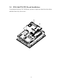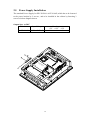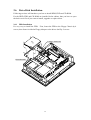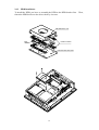
1
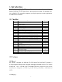
PPC-5050A 15” TFT Panel PC Ver 1.0 Manual Revision 1.0 October 7,2002 Copyright Notice ©Copyright 2002 by ICP Electronics Inc. All Rights Reserved. Revision: 1.0. Oct., 7 2002. The information in this document is subject to change without prior notice in order to improve reliability, design and function and does not represent a commitment on the part of the manufacturer. In no event will the manufacturer be liable for direct, indirect, special, incidental, or consequential damages arising out of the use or inability to use the product or documentation, even if advised of the possibility of such damages. This document contains proprietary information protected by copyright. All rights are reserved. No part of this manual may be reproduced by any mechanical, electronic, or other means in any form without prior written permission of the manufacturer. Trademarks PPC-5050A is a registered trademark of ICP Electronics Inc. IBM PC is a registered trademark of International Business Machines Corporation. Intel is a registered trademark of Intel Corporation. Other product names mentioned herein are used for identification purposes only and may be trademarks and/or registered trademarks of their respective companies. If you have any questions or need other information, please visit to our web site. http://www.iei.com.tw 1 Revision History Revision 1.00 Revision Note Initial release of the PPC-5050A user’s manual Date Oct. 7 20002 Note: The author assumes no responsibility for any errors or omissions that may appear this manual nor does the author make a commitment to update the information contained herein. 2 Table of Contents 1. INTRODUCTION....................................................................................................4 1.1 CHECKLIST ............................................................................................................4 1.2 FEATURES ..............................................................................................................4 1.3 SPECIFICATIONS.....................................................................................................5 1.4 MECHANICAL DIMENSION .................................................................................9 2. SYSTEM SETUP ...................................................................................................10 2.1 THE REVERSE SIDE OF PPC-5050A..................................................................10 2.2 THE REVERSE SIDE OF THE REAR CABINET ...................................................... 11 2.3 THE SIDE VIEW OF PPC-5050A........................................................................12 2.4 POS-566/370 CPU BOARD INSTALLATION .......................................................13 2.5 POWER SUPPLY INSTALLATION ..........................................................................14 2.6 DRIVE DISK I NSTALLATION ...............................................................................15 2.6.1 FDD Installation......................................................................................15 2.6.2 HDD Installation .....................................................................................16 2.6.3 CD-ROM Installation...........................................................................17 2.7 PANEL MOUNTING ............................................................................................18 2.8 WALL MOUNTING .............................................................................................19 2.9 ARM MOUNTING ...............................................................................................20 2.10 RACK MOUNTING ...........................................................................................21 APPENDIX A EXPLODED DIAGRAM ..............................................................22 APPENDIX B USER MODE OSD FEATURE DESCRIPTION .......................23 APPENDIX C DISPLAY INTERFACE................................................................26 APPENDIX D TOUCH PANEL CONTROLLER ...............................................27 3 1. Introduction The PPC-5050A, 15" LCD TFT Panel PC, takes advantages of modern flat-panel display, POS-566/370 CPU board, drive spaces and power supply for minimum size. It is an IBM PC/AT compatible computer specially designed to meet the applications for industrial environment. 1.1 Checklist Item 1 2 3 4 5 6 7 8 9 10 11 12 12 13 14 15 16 17 18 19 Description Y Cable Power Cable Wall Mounting kit BOLT M4*8 Mounting Clip Round Head Screw M5*50 Round Head Screw M3*6 Flat Head Screw M3*6 Screw Accessories (19600-000103) Screw Accessories (19600-000104) Screw Accessories (19600-000105) Screw Accessories (19600-000063) A49 SLIM-05 JUMPER Pitch:2.0 POS-566/370 User’s Manual PPC-5050 User’s Manual CD-ROM Driver Touch Panel Pen (Option) Touch Panel Driver (Option) Qty. 1 1 1 4 10 10 10 5 1 1 1 1 1 1 10 1 1 1 1 1 1.2 Features CPU Board PPC-5050A is designed for POS-566/370 CPU board. The POS-566/370 board is a LPX specification board, which equipped with high performance socket 370 Celeron Pentium III® CPU, LCD/CRT and 10/100Mbps Ethernet, designed for the system manufacturers, integrators, or VARs to provide all the performance, reliability, and quality. LCD Display 4 The PPC-5050A is equipped with a 15" TFT LCD. Power Supply The standard industrial power supply of PPC-5050A is equipped with ACE-916AP. Touch Screen (option) Dynapro resistive touch screen. HDD, FDD & CD-ROM It is suggested to be equipped with one 2.5” internal HDD, one slim FDD, and one slim CD-ROM. 1.3 Specifications z z z z Disk Drive Bay: Support one 2.5" HDD, one slim FDD, and one slim CD-ROM. Best solution for Panel mount man machine interface. Dimensions : Front Panel: 410mm x 309mm x 9mm (WxHxD) Cabinet: 383.6mm x 282.6mm x 97.6mm (WxHxD) LCD Display: TTL LCD connector interface to support screen reverse function. Display Model CHI MEI Display Type LCD model Resolution Display colors Brightness LCD MTBF Backlight MTBF Supply Voltage 15” TFT color M150X2-T05 1024x768 262,144 color 250 cd/m2 50,000 hrs 50,000 hrs 3.3V z Dynapro Touch Screen (option) Type: Analog Resistive Resolution: Continuous Light transmission: Typical value 75% Surface Hardness: 4H (Test condition: ASTM D3363-92A) 8-wire touch screen Support driver: Supports Linux,MS-DOS,Windows 3.1/95/ 98/CE,ME/2000/NT,OS/2,MAC,etc. z Environmental specifications 5 Operating Temperature : 0 ~ 50℃ Relative Humidity: 5~85% @40℃ , non-condensing Vibration: 5 to 17 Hz, 0.1"double-amplitude displacement, 17 to 500 Hz, 1.5 G peak to peak. z Industrial Power Supply: ACE-916AP series Power Supply High reliability triple outputs switching Power Supply with height 40.6mm only Standard Power Supply: ACE-916AP Optional Power Supply: ACE-916A, ACE-816A/ AP and ACE-815T Operating temperature: -0°C to 50°C Vibration: 10-55Hz at 2G 3 min. period, 30 min. along X, Y, and Z axis Shock: 10G for 20ms once on each X, Y, and Z axis Safety: meet UL1950/TUV: EN60950 EMI: meet FCC class B /CISPR:EN 55022 class B/CE: Harmonic EN61000-3-2 Warning: Whenever you need to take off a part for either maintenance or upgrading purpose, you should switch off the power supply and unplug the power cord first. z Specifications of POS-566 CPU Board: The POS-566/566L 450MHz K6-3 / Pentium Processor Multimedia POS Control SBC provides the following specifications: • ® ® ® ® ® CPU: Pentium MMX up to 233Mhz, AMD K6 /K6 -2/K6 -3 up to 450MHz, IDT C6, Cyrix 6x86MX, etc. Processor • RAM: 3x DIMM sockets up to 768MB SDRAM • Cache memory: 512KB Pipelined Burst SRAM on board • Bus: PCISA bus expansion to support ISA and PCI bus signal • Chipset: Ali 5, support 100MHz CPU clock • LCD/CRT Controller: CHIPS 65555 2MB EDO RAM on board • Support 3.3V or 5V flat panel. • Support Mono, Color STN, TFT, EL,.. wide range flat panel. • Optional One Channel or Two Channels LVDS module. • 10/100Mbps Ethernet Controller: Realtek RTL8139 IEEE 802.u 100 BASE-TX standard Dual Auto-sensing interface to 10MBps or 100MBps networks 6 RJ45 connector for 10BASE-T and 100BASE-TX Full duplex capability, full software driver support. • Creative Sound Blaster 16 compatible and Roland MPU401 UART Mode compatible • Four high speed Serial ports : three RS-232C, one RS-232C, or RS-422/485 Port • Parallel Ports : Two SPP/EPP/ECP Parallel Ports • Enhanced IDE Interface : One 44-pin Header for 2.5” HDD One 40-pin Header for 3.5” HDD • PCISA • Isolated Digital I/O: 4 Digital Inputs and 4 Digital Output channels • IrDA port: Support Serial Infrared (SIR) and Amplitude Shift Keyed IR (ASKIR) interface. • Two USB ports: Support dual USB ports for future expansion. • Watchdog timer: Can be set by 1, 2, 10, 20, 110 or 220 seconds period. Reset or NMI is generated when CPU does not periodically trigger the timer. • TM Bus Expansion to support ISA and PCI bus signal 2 TM Function: A special designed 1Kbit EEPROM (non volatile E Key memory) provided to accept read/ write data by customer’s program. It is useful to store system ID, Password, Critical Data on the board. • Keyboard connector • Mouse: PS/2 Mouse Port on-board. • Power Consumption: +5V/5.5A (AMD K6-2 350MHz, 384MB SDRAM) +12V: 170mA , -12V : 60mA z • Support ATX and AT power supply • Operating Temperature: 0 ° ~ 60° C ( CPU needs Cooler) • Operating Humidity: 5-95% non-condensing Specifications of POS-370 CPU Board: The POS-370 socket 370 Celeron Pentium III Processor Multimedia POS Control SBC provides the following specifications: • ® CPU: Celeron & Pentium III Processor • RAM: 2x DIMM sockets up to 1GB SDRAM. 7 • Bus: PCI bus expansion to support . • Chipset: SIS630, support 133MHz CPU clock • LCD/CRT Controller: On chip SIS300 • Support 3.3V or 5V flat panel. • Support Mono, TFT, EL... wide one channel that panel. • Optional One Channel or One Channel LVDS module. • 10/100Mbps Ethernet Controller: On chip SIS900 LAN BASE-TX standard Dual Auto-sensing interface to 10MBps or 100MBps networks RJ45 connector for 10BASE-T and 100BASE-TX Full duplex capability, full software driver support. • On CHIP AC97 SIS 7018 • Four high speed Serial ports : three RS-232C, one RS-232C, or RS-422/485 Port • Parallel Ports : Two SPP/EPP/ECP Parallel Ports • Enhanced IDE Interface : (DMA 66) Two 40-pin Header for 3.5” HDD • PCI Bus Expansion to support PCI bus signal • Isolated Digital I/O: 4 Digital Inputs and 4 Digital Output channels • IrDA port: Support Serial Infrared (SIR) and Amplitude Shift Keyed IR (ASKIR) interface. • Five USB ports: Support dual USB ports for future expansion. • Watchdog timer: Can be set by 1 min.(min.) period. • Keyboard connector • Mouse: PS/2 Mouse Port on-board. • Power Consumption: +5V/6.5A (see POS-370 manual)) • Support ATX and AT power supply • Operating Temperature: 0 ° ~ 60° C ( CPU needs Cooler) • Operating Humidity: 5-95% non-condensing 8 1.4 Mechanical Dimension Front Panel: 410mm x 309mm x 9mm (WxHxD) Cabinet: 383.6mm x 282.6mm x 97.6mm (WxHxD) 9 2. System Setup The PPC-5050A, 15" LCD TFT Panel PC, is provided complete kit for your operation. The following sections of this chapter will help your installation and maintenance. 2.1 The Reverse Side of PPC-5050A The below diagram shows the reverse side of PPC-5050A. For maintenance, installation or upgrade, you have to remove the back cover first by unfastening 9 screws as the diagram shown. Warning: Before any installation/un-installation, please notice any effects of static electricity. 10 2.2 The Reverse Side of the Rear Cabinet The below figure indicates the reverse side of the rear cabinet. OSD COM 4 COM 3/RS422/RS485 PRINTER 2 PCI add-on card MIC SPEAKER LINE-IN ACP POWER INPUT 110V/230V SWITCH VGA COMPACT FLASH PRINTER 1 COM 2 COM 1 POWER SW KEYBOARD USB PORT LAN 11 2.3 The Side View of PPC-5050A One FDD and CD-ROM are accessible for your operation on the driver frame. FDD CD ROM 12 2.4 POS-566/370 CPU Board Installation To install the POS-566/370 CPU Board, you have to place the board into the cabinet and then fasten it by four screws. 13 2.5 Power Supply Installation The standard Power Supply for PPC-5050A is ACE-916AP, which has to be fastened to the power bracket by 2 screws , and to be installed in the cabinet by fastening 3 screws as below diagram shown. Output Spec. at 50°C Model ACE-916AP ER W O P BR KE AC T Input Voltage Max Output +5V +12V –12V 16A 6A 0.3A 90V to 264VAC AC E- 91 6A P 14 2.6 Drive Disk Installation Following sections will introduce you how to install HDD, FDD and CD-ROM. For the HDD, FDD and CD-ROM are installed in the cabinet, thus you have to open the back cover first if you want to install , upgrade or replace them. 2.6.1 FDD Installation It’s very easy to install the FDD. First, fasten the FDD to the Floppy Chassis by 4 screws, then fasten it with the Floppy Adapter to the drives shelf by 2 screws. FLOPPY ADAPTOR FD D FDD BRACKET 15 2.6.2 HDD Installation To install the HDD, you have to assemble the HDD to the HDD bracket first. fasten the HDD bracket to the drives shelf by 4 screws. HDD BRACKET TOP HDD MOUNT STRIPS HDD BRACKET BOTTOM 16 Then, 2.6.3 CD-ROM Installation To install CD-ROM. You have to assemble the CD-ROM into the bracket, then fasten the CD-ROM Adaptor to the CD-ROM. Finally you have to fasten this unit to the drives shelf. 2-M2*6 M3*6 2-M2*2 CD-ROM Adaptor CD -R O SPACER M 2-M2*3 17 2.7 Panel Mounting PPC-5050A is designed for panel mounting. Before mounting the PPC-5050A into panel, you have to check the cut out dimension first. Then mount it into panel by four supporters. Please refer to diagrams below. 286.0 387.0 UNIT:mm THE DIMENSION IS FOR PANEL MOUNTING (The flat panel thickness is 6mm or 18 less than 6mm) 2.8 Wall Mounting PPC-5050A is suitable for Wall mount. TO E TH LL WA TO TO LL WA E TH L AL W E TH TO E TH LL WA 19 2.9 Arm Mounting PPC-5050A is not only suitable for panel mounting but also for 75/100mm interface pads for arm mounting; and the specification conform to the proposed VESA standard. 100 75 75 100 88 20 2.10 Rack Mounting DM/SRM/PPC serial product provide option rackmount kit for industrial Rack. The following diagram shows how to mount DM/SRM serial product onto the 19" Rack. STEP 2 STEP 1 Rackmount-Kit 21 Appendix A Exploded Diagram 1 2 3 4 5 6 7 8 9 10 11 12 13 14 15 ITEM 1 2 3 4 5 6 7 8 9 10 11 12 13 14 15 DESCRIPTION BACK COVER HDD BRACKET (TOP) HDD BRACKET (BOTTOM) FDD BRACKET CDROM BRACKET DRIVES SHELF REAR BRACKET REAR BRACKET REAR CARD FRAME VGA BRACKET FRONT BRACKET 15” TFT LCD TOUCH PANEL HOLDER TOUCH PANEL FRONT PANEL 22 Q’TY 1 1 1 1 1 1 1 1 1 1 1 1 1 1 1 Appendix B User Mode OSD Feature Description z Auto-Adjustment This feature will automatically adjust the H/V position, frequency, phase, and black level. z Auto Phase This feature will automatically adjust the sampling. z Brightness This option is used to adjust the brightness of screen. This function will adjust the offset value of ADC. Setting this value too high or too low will decrease the quality of image. z Contrast This option is used to adjust the contrast level on the screen, and will adjust the gain value of ADC. Adjusting this value too high or too low will decrease the quality of image. 23 z DOS/GFX This option is used to select VGA input signal in either text or graphic mode. (This option is only available on resolution of 720/640x400 or 720/640x350). 400 and 350 standard IBM modes have the same Hsync. and Vsync. values, and AV-9261 MPU can not differentiate between them automatically, so the user should adjust them manually to match the proper VGA mode . z H. Position This option is used to adjust horizontal display position of image. z V. Position This option is used to adjust vertical display position of image. z Language This option is used to select the language used on the OSD display. AV-9261 can support 2 languages on the OSD display. English is the default language. 24 z Revert This option is used to reset the original parameters to the factory’s OSD data area of the system EEPROM 24c16 device in order to re-initialize the AV-9261 system. When a user over-adjusts the OSD data and sees no improvement in the quality, then the user can select this feature and MPU will reload default BIOS setting and re-initialize the system. z Save This option is used to save the parameters into the EEPROM 24c16 system’s user OSD adjustment data area and close the OSD. Whenever the user adjusts any parameters, this option will save the changed data on to the EEPROM so that the MPU will use the stored data to initialize the AV-9261 system on future re-boots. z Main Menu Each level of the OSD has an item named Main Menu, which allows the user to exit the current level and return to the main menu. z Exit Press the EXIT key to exit the OSD menu when you are finished. 25 Appendix C Display Interface For POS-370/566 D LC I NV ER TE 61 -92 V A R OS D 6 0/ 5 37 S PO 26 6 Appendix D Touch Panel Controller The optional touch screen provides RS232 interface and the controller of eGalax are as the below figure shown. T To c ou e an hP l E RC U O RS T O oP WE V +5 To RS 2 -2 3 Pi ea nH r de 27 Touch Panel Control Board