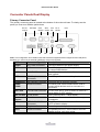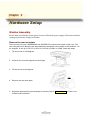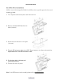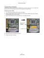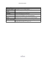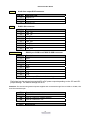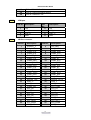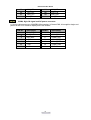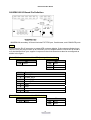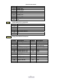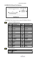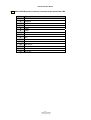
1
User's Manual
Nova 3710 Motherboard, 12.1 & 15 inch LCD’s
NOVA 3710 Main Board
NOVA 3710 Main Board
Federal Communications Commission (FCC)
This equipment has been tested and found to comply with the limits for a Class A digital device,
pursuant to Part 15 of the FCC Rules. These limits are designed to provide reasonable
protection against harmful interference in a residential installation. This equipment generates,
uses, and can radiate radio frequency energy and, if not installed and used in accordance with
the instructions, may cause harmful interference to radio communications. However, there is no
guarantee that interference will not occur in a particular installation. If this equipment does
cause harmful interference to radio or television reception, which can be determined by turning
the equipment off and on, the user is encouraged to try to correct the interference by one or
more of the following measures:
Reorient or relocate the receiving antenna.
Increase the separation between the equipment and the receiver.
Connect the equipment to an outlet on a circuit different from that to which the receiver is
connected.
Consult the dealer or an experienced radio/TV technician for help.
Shielded interconnect cables and shielded AC power cables must be employed with this
equipment to insure compliance with the pertinent RF emission limits governing this device.
Changes or modifications not expressly approved by the system’s manufacturer could void the
user’s authority to operate the equipment.
Declaration of Conformity
This device complies with part 15 of the FCC Rules. Operation is subject to the following two
conditions:
1. This device may not cause harmful interference, and
2. this device must accept any interference received, including interference that may cause
undesired operation.
NOVA 3710 Main Board
NOVA 3710 Main Board
DHHS- the CD-ROM Drive
FDA Regulations require the following statement for all laser-based devices:
“Caution, Use of controls or adjustments or performance of procedures other than those
specified herein may result in hazardous radiation exposure.”
Caution: This appliance contains a laser system and is classified as a “CLASS 1 LASER PRODUCT”.
To use this model properly, read the instruction manual carefully and keep this manual for future
reference. In case of any trouble with this model, please contact your nearest “Authorized Service
Station”. To prevent direct exposure to the laser beam, do not try to open this enclosure.
NOVA 3710 Main Board
Important Safety Information
SAFETY INSTRUCTIONS
1.
2.
3.
4.
5.
6.
7.
8.
9.
10.
11.
12.
13.
14.
15.
Please read these safety instructions carefully.
Keep this User’s Manual for later reference.
Disconnect this equipment from the AC outlet before cleaning. Don’t use liquid or spray
detergent for cleaning. Use only a moistened sheet or cloth.
For pluggable equipment, the socket-outlet should be installed near the equipment and
should be easily accessible.
Keep this equipment from humidity.
Lay this equipment on a stable surface when installing.
Do not leave this equipment in an non-air-conditioned environment, or in a storage
temperature above 60∘C. Such conditions may damage the equipment.
The openings on the enclosure are for air convection and protect the equipment from
overheating. DO NOT COVER THE OPENINGS.
Check the voltage of the power source when connecting the equipment to the power outlet.
Place the power cord so that it will not be stepped on. Do not place anything over the
power cord. The power cord must be rated for the product and for the voltage and current
marked on the product’s electrical ratings label. The voltage and current rating of the cord
should be greater than the voltage and current rating marked on the product.
All cautions and warnings on the equipment should be noted.
If the equipment is not used for a long time, disconnect the equipment from the mains to
avoid damage.
Never allow liquid into ventilation openings. This could cause fire or electrical shock.
Never open the equipment. For safety reasons, qualified service personnel should only
open the equipment.
If one of the following situations arises, get the equipment checked by service personnel:
a. The Power cord or plug is damaged.
b. Liquid has penetrated the equipment.
c. The equipment has been exposed to moisture.
d. The equipment does not work well or you cannot get it work according to the user’s
manual.
e. The Equipment has been dropped and damaged.
f. The equipment has obvious signs of damage.
NOVA 3710 Main Board
Copyright
The information in this guide is subject to change without prior notice.
The manufacturer shall not be liable for technical or editorial errors or omissions contained
herein, nor for incidental or consequential damages resulting from the furnishing, performance,
or use of this material.
This manual contains information protected by copyright. No part of this manual may be
photocopied or reproduced in any form without prior written consent from the manufacturer.
© 2001 All rights reserved.
The software described in this guide is furnished under a license agreement or nondisclosure
agreement. The software may be used or copied only in accordance with the terms of the
agreement.
Product names mentioned herein may be trademarks and/or registered trademarks of their
respective companies.
First Edition November 2001
NOVA 3710 Main Board
Table of Content
Chapter 1
Introduction
1
1
Gladius Characteristics.......................................................................................................... 1
How to Use This Manual ....................................................................................................... 2
A Visual Tour of Gladius ........................................................................................................ 3
What comes with Gladius ............................................................................................... 4
Dimensions 12.1”............................................................................................................ 6
Dimensions 15”............................................................................................................... 7
Connector Panels Single Display .......................................................................................... 8
Primary Connector Panel ............................................................................................... 8
Second Connector Panel................................................................................................ 9
Connector Panels Dual Display ........................................................................................... 10
Primary Connector Panel ............................................................................................. 10
Second Connector Panel.............................................................................................. 11
Chapter 2
Hardware Setup
12
12
Gladius Assembly ................................................................................................................ 12
Remove the rear neck plate ......................................................................................... 12
Hard Disk Drive Installation .......................................................................................... 13
Compact Flash Installation ........................................................................................... 14
Magnetic Card Reader Installation ............................................................................... 15
MCR Parameter Modification ....................................................................................... 17
VFD Customer Display Installation............................................................................... 18
External Floppy Drive Installation ................................................................................. 20
CD-ROM Installation..................................................................................................... 20
Cash Drawer Installation .............................................................................................. 20
Optional Second LCD Panel Display............................................................................ 21
OSD Settings for Second LCD Panel ........................................................................... 22
CMOS Setup ....................................................................................................................... 23
Chapter 3
Software Setup
24
24
VGA Driver Installation ........................................................................................................ 24
SIS300 driver installation Windows 98 ......................................................................... 24
SIS300 driver installation Windows 2000 ..................................................................... 26
Second LCD Panel Driver ................................................................................................... 28
C & T 69000 VGA Driver Installation Windows 98 ....................................................... 28
Enable Second LCD Panel Settings Windows 98 ........................................................ 30
C & T 69000 VGA Driver Installation Windows 2000 ................................................... 31
Enable Second LCD Panel Settings Windows 2000 .................................................... 37
LAN Driver Installation......................................................................................................... 39
NOVA 3710 Main Board
Realtek LAN Driver Installation Windows 98 ................................................................ 39
Realtek LAN Driver Installation Windows 2000 ............................................................ 41
Audio Driver Installation....................................................................................................... 42
Audio Driver Installation Windows 98 ........................................................................... 42
Audio Driver Installation Windows 2000 ....................................................................... 45
ELO Touch Tools Installation .............................................................................................. 47
ELO Touch Tools Installation for Windows 98 and 2000.............................................. 47
ELO Control Panel........................................................................................................ 49
Chapter 4
Specifications
52
52
I/O board Configuration ....................................................................................................... 54
9000PB0090 I/O Board Pin Definition .......................................................................... 54
9000PB0100 I/O Board Pin Definition .......................................................................... 59
9000PB0230 I/O Board Pin Definition .......................................................................... 61
Chapter 5
Troubleshooting
64
64
Power is on, but there is no Panel Display ................................................................... 64
Cannot Detect HDD...................................................................................................... 65
Touch Panel Does not Work......................................................................................... 65
ELO Touch Panel Cannot Calibrate Correctly.............................................................. 65
Second LCD Panel is Not Functioning Properly........................................................... 65
PS/2 Keyboard is not Functioning Normally ................................................................. 66
MCR is not Functioning Properly.................................................................................. 66
VFD Display is not Functioning Properly ...................................................................... 67
External CD-ROM is not Functioning Properly ............................................................. 67
LAN is not Functioning Properly ................................................................................... 67
COM1, COM2 and LPT1 are not Functioning Properly ................................................ 67
Cash Drawer Port is not Functioning Properly ............................................................. 68
USB device is not Functioning Properly ....................................................................... 68
External FDD is not Functioning Properly .................................................................... 68
NOVA 3710 Main Board
Chapter 1
Introduction
Gladius Characteristics
¾
Gladius uses a high speed processor capable of handling a high capacity of data
efficiently.
¾
Gladius’s solid quality Aluminum housing distinguishes it from ordinary plastic housings.
¾
The Gladius touch terminal all-in-one design combines a powerful PC, multiple LCD
and touch screens, which are suitable for any market. The primary LCD panel can be
tilted at multiple angles.
¾
Gladius’s functionality extends far beyond the standard setup. Gladius can be adapted
for a variety of uses with the addition of any of the following options: Magnetic Card
Reader, VFD/LCD customer display and cashdrawer, Modem, LAN, Audio devices,
Compact Flash or USB devices (all available upon request).
¾
Gladius’s security is designed to prevent data theft. The Gladius system is comprised of
an internal 3.5” HDD and removable external CD-Rom and FDD making it hard to copy
data without authority.
¾
The solid aluminum design enhances heat dissipation and passes EMI testing.
1
NOVA 3710 Main Board
How to Use This Manual
This manual contains all the information you need to set up and use Gladius. In addition, you can
also consult the manuals for the operating system and added hardware.
Chapter 1
Provides an introduction to Gladius and this manual.
Chapter 2
Provides all necessary information for all hardware setup.
Chapter 3
Provides the necessary information for installing the Video drivers and the touch
screen tools, Audio and LAN drivers.
Chapter 4
Lists all Gladius specifications and Information for the 9000PB0090, 9000PB0100
and 9000PB0230 I/O board configuration.
Chapter 5
Provides information for troubleshooting Gladius.
2
NOVA 3710 Main Board
A Visual Tour of Gladius
Before you start, take a few moments to become familiar with Gladius.
3
NOVA 3710 Main Board
What comes with Gladius
The following items are standard with Gladius:
¾
Main system with LCD panel
¾
Base
¾
ATX power supply
¾
Gladius user’s guide
¾
Nova 3710 motherboard user’s guide
¾
ELO touch screen driver CD
¾
Motherboard chipset driver CD
¾
AC power cord
Gladius and power adapter
Gladius with MCR
Gladius with VFD
4
NOVA 3710 Main Board
The following items are optional:
¾
Magnetic card reader (MCR) and bracket
¾
External CD-ROM drive with cable
¾
External floppy disk drive with cable
¾
VFD customer display
Optional accessories
5
NOVA 3710 Main Board
Dimensions
12.1”
Gladius Dimensions
Gladius and MCR
Dimensions
Gladius and VFD
customer display
6
NOVA 3710 Main Board
Dimensions
15”
Gladius
Dimensions
Gladius and MCR
Dimensions
Gladius and VFD
customer display
7
NOVA 3710 Main Board
Connector Panels Single Display
Primary Connector Panel
The primary connector panel is located at the bottom of the main unit base. To clearly see the
panel you must turn Gladius upside down.
EXT FDD
Power
Cash
VFD/
Drawer COM4
USB
LAN
Line
Out
KBD
PS/2
Mouse
COM2
LPT1
COM1
I/O Port
Connector Type
Description
Power
DC Power Connector
Connects Gladius to the power supply.
USB
USB
LAN
LAN RJ45 Connector
KBD
The USB (Universal Serial Bus) port can be used
to connect USB devices.
The LAN port is used to hook Gladius to a local
area network.
The KBD port for an external keyboard.
PS/2 Keyboard
Connector
PS/2 Mouse Connector PS2 ports can be used for a mouse.
DSUB Connector
The serial ports COM1/COM2 can be used to
connect serial devices such as a mouse or a
fax/modem.
26 PIN SCSI II
The FDD port is used to attach an external 1.44MB
Connector
floppy disk driver.
RJ11 Connector
Cash Drawer Connector, 12 V Actuation support
for solenoid.
VFD/ COM4 RJ45
The VFD port is used to attach An RJ45 cable for
Connector
a VFD customer display.
Earphone Connector
The audio port is for speakers.
DSUB Connector
The parallel port LPT1 can be used to connect
parallel devices, such as a printer.
PS2/Mouse
COM1
COM2
EXT FDD
Cash
Drawer
VFD
Line Out
LPT1
8
NOVA 3710 Main Board
Second Connector Panel
The Second connector panel is located on left side of the back of the main unit. It comes with a
cover that needs to be removed to install a CD ROM Driver or a VGA monitor.
I/O Port
Connector Type
Description
VGA
VGA Connector
CD-ROM
36 PIN SCSI II Connector
The VGA port is for an external LCD or CRT
monitor that mirrors the primary display.
The CD-ROM port is used to attach an external
CD-ROM.
9
NOVA 3710 Main Board
Connector Panels Dual Display
Primary Connector Panel
The primary connector panel is located at the bottom of the main unit base. To clearly see the
panel you must turn Gladius upside down.
DC 12v
output
EXT VGA
Power
Cash
VFD/ Line
Drawer COM4 Out
USB
LAN
KBD
PS/2
Mouse
COM2
LPT1
COM1
Note: This configuration is for Gladius units that have been supplied with an integral second LCD panel,
therefore you must use an external USB floppy drive unit if required.
I/O Port
Connector Type
Description
Power
DC Power Connector
Connects Gladius to the power supply.
USB
USB
LAN
LAN RJ45 Connector
KBD
The USB (Universal Serial Bus) port can be used
to connect USB devices.
The LAN port is used to hook Gladius to a local
area network.
The KBD port for an external keyboard.
PS/2 Keyboard
Connector
PS/2 Mouse Connector PS2 ports can be used for a mouse.
DSUB Connector
The serial ports COM1/COM2 can be used to
connect serial devices such as a mouse or a
fax/modem.
15 PIN VGA Connector The Ext VGA port is used to attach an external 2nd
Panel display or CRT monitor.
2 PIN Socket
This is used for the 2nd Panel display.
RJ11 Connector
Cash Drawer Connector, 12 V Actuation support
for solenoid.
VFD/ COM4 RJ45
The VFD port is used to attach An RJ45 cable for
Connector
a VFD customer display.
Earphone Connector
The audio port is for speakers.
DSUB Connector
The parallel port LPT1 can be used to connect
parallel devices, such as a printer.
PS2/Mouse
COM1
COM2
EXT VGA
DC 12V Out
Cash
Drawer
VFD
Line Out
LPT1
10
NOVA 3710 Main Board
Second Connector Panel
The Second connector panel is located on left side of the back of the main unit. It comes with a
cover that needs to be removed to install a CD ROM Driver or a VGA monitor.
I/O Port
Connector Type
Description
VGA
VGA Connector
CD-ROM
36 PIN SCSI II Connector
The VGA port is for an external LCD or CRT
monitor that mirrors the primary display.
The CD-ROM port is used to attach an external
CD-ROM.
11
NOVA 3710 Main Board
Chapter 2
Hardware Setup
Gladius Assembly
Please make sure that the system power is turned off and the power supply is disconnected when
making any hardware changes to Gladius.
Remove the rear neck plate
There are two I/O ports, 9000PB0090 and 9000PB0100, located on the back of the neck. The
rear neck plate must therefore be removed before alterations can be made to the hardware. As
an example, to set up for DC+5V or DC+12V at Pin9 of COM1 or COM2, follow the steps:
1. Tilt the screen to 180 degrees.
2. Unscrew the 2 screws adjacent to the hinges.
3. Tilt the screen to 90 degrees.
4. Remove the rear neck plate.
5. Select the appropriate jumper settings as needed; refer to CON4&CON41 of Com1 and
COM2 D-sub connector.
12
NOVA 3710 Main Board
Hard Disk Drive Installation
Gladius comes with an empty hard disk drive (HDD), unless a special request has been made.
Installing a HDD
1. Turn off power and remove power cable from main unit.
2. Remove the Base/HDD Plate from the
base (4 screws).
3. Secure the hard disk drive on the plate
(4 screws).
4. Plug the IDE and power cable to the HDD. The red stripe on the ribbon cable should be
aligned with PIN1 on the IDE connector of HDD.
5. Put the plate back to the base and
secure with 4 screws.
6. Connect the main unit power.
Note: If the HDD does not work normally, please refer to troubleshooting.
13
NOVA 3710 Main Board
Compact Flash Installation
Gladius will configure Compact Flash in IDE mode as secondary master after it is installed. The
next available drive letter will be automatically assigned to Compact Flash.
Installing Compact Flash
1. Turn off power and remove power cable from Gladius.
2. As the compact Flash socket is located on the soldering side of M/B, remove the 4 screws
and disassemble the front panel plate.
3. Insert Compact Flash and lock the black lever in a 90 degree position.
Black lever in a
90 degree
position
Compact Flash
4. Reassemble front panel plate to main unit.
5. Connect the main unit power.
14
NOVA 3710 Main Board
Magnetic Card Reader Installation
An optional Magnetic Card Reader (MCR) can be installed on the right side of Gladius.
Magnetic Card Reader (MCR)
Installing an MCR
1. Turn off system power.
2. Unplug the loopback from the MCR socket. The
MCR socket is found on the right side on the
back of the main Unit.
3. Attach the MCR Assembly to the main unit and
connect the MCR cable to the MCR socket.
4. Secure the MCR to the main unit with 2 screws.
15
NOVA 3710 Main Board
5. Turn on system power.
Note: If the MCR does not work normally, please refer to troubleshooting.
Attention: The loopback or the MCR cable must be inserted in the socket for an external keyboard to
function with Gladius.
16
NOVA 3710 Main Board
MCR Parameter Modification
This option is for users who need to customize the MCR parameters for a particular task.
Some of the useful parameters include:
The selection of country code, other than the default English.
The choice of track combinations.
The preamble/postamble codes.
The MCR parameters can be modified by using the supplied utility program.
The utility can be found on the CD that came with your system in the “Utilities” folder. The
program name is msr_v12_win.zip.
If you are upgrading and earlier system to include our MCR reader, then this utility can located on
our website at http://www.firich.com.tw/tech_drivers.htm in the section labeled as “MSR Utility”.
Unzip this file onto your system hard disk, in a folder of your choice.
It will also create 3 subfolders named Disk1, Disk2, and Disk3.
Change to the folder “Disk1” and run the “Setup.exe” program, and follow the simple onscreen
instructions.
When the installation finishes, you will find that a new folder has been created in your “Program files”
folder, labeled as “Decoder” with a subfolder named “S64 Decoder”.
Now change folder to C:\Program Files\Decoder\S64 Decoder and run the program named
“S64_cfg.exe”.
When the program has loaded please select the Magnic_Reader menu item as in the following
picture. By using the 3 top items listed; Interface, Communication and Miscellaneous, you will
be able to alter many of the parameters associated with the MCR unit.
When you have finished your modifications and are sure that they are set exactly how you want
them to be, just click on the menu item Transmit to download the new parameter to the MCR unit.
Please refer to the Help menu for any further assistance.
17
NOVA 3710 Main Board
VFD Customer Display Installation
An optional VFD customer display can be installed on the back of Gladius.
Rear view with VFD attached.
Installing a VFD
1. Turn off system power.
2. Make sure that JP1 and JP2 on the secondary I/O board 9000PB0100 are set correctly. It's
important to note that the supply voltage for the customer display has been set to +12V, which
is for VFD type. IF an LCD customer display is chosen, please change it to +5V through JP1
on 9000PB0100. Please refer to page 59, Mode1 RJ45 connector used for VFD.
3. Remove the VFD Mounting Cover
from the base.
4. Secure the VFD Holder to the base
with 3 screws and place VFD display
into the holder.
18
NOVA 3710 Main Board
5. Connect the VFD RJ45 cable in the
VFD/COM4 port on the I/O panel
which located under the base.
6. Turn on VFD power switch, then turn
on system power.
Note: If the VFD does not display correctly after an application is loaded, please refer to troubleshooting.
19
NOVA 3710 Main Board
External Floppy Drive Installation
1. Please make sure the Driver A in the CMOS setup is enabled for 1.44MB.
2. Turn off system power.
3. Connect FDD cable to the EXT FDD port of Gladius.
Note: If the EXT FDD does not work normally, please refer to troubleshooting.
CD-ROM Installation
1. Please make sure the IDE 2 in the CMOS setup is enabled.
2. Turn off the power.
3. Plug the CD-ROM cable to the CD-ROM port.
Note: If the CD-ROM cannot be detected by the system, please refer to troubleshooting.
Cash Drawer Installation
1. Before connecting the cash drawer to Gladius, please make sure the driver voltage and cable
pin assignment of the cash drawer matches the definition of the cash drawer port of Gladius.
Please refer to page 68 Cash Drawer .
2. Plug cash drawer cable into cash drawer port.
Note: If the cash drawer cannot be detected by the system, please refer to troubleshooting.
3. Up to two cash drawers may be driven from this port. The driving voltage of solenoid is
DC+12V. I/O port 408h is used for solenoid operation.
To open drawer1, write E0h to this port, wait 200 msec, then write F0h to turn off the drive.
To open drawer2, write D0h to this port, wait 200 msec, then write F0h to turn off the drive.
20
NOVA 3710 Main Board
Optional Second LCD Panel Display
An optional second LCD panel can be easily installed on Gladius. To install a second
LCD panel Gladius must have mainboard NOVA3710DV installed.
There are two standard pole heights that may be ordered, 150mm and 400mm.
The mechanical fitting of the second panel display is a very simple process.
Position the Gladius onto it’s side.
Remove the 3 screws and Mounting Cover from the base unit.
Position the already assembled Second Panel Display, Pole and Holder to the base and
secure firmly with the 3 screws.
Now connect the Second Panel Display cables to the Power and VGA sockets on the
underside of the Gladius unit. If you also ordered the second display Touch panel option
then connect this to the COM4 socket.
Note. CMOS BIOS settings should be altered to make COM4 use IRQ11, and both SIS
and C&T VGA chips should be enabled.
SIS should be set as the primary display and C&T as the secondary display.
Dependant upon which operating system is used, drivers will have to be installed,
therefore please refer to the CD that came with your Gladius, or visit our website at:
http://www.firich.com.tw/tech_drivers.htm
21
NOVA 3710 Main Board
OSD Settings for Second LCD Panel
Gladius secondary LCD panel has built-in OSD (on screen display) controls to adjust various
display parameters. The control buttons are located on the right side of the back cover.
OSD Settings
There are four buttons on the OSD panel: Select, Down, Up, and Enter. The functions of these
four buttons are as follows:
Press to open the OSD window.
Menu
Back one menu level up.
Press to exit the OSD window while in OSD mode.
DownArrow
Press to scroll item selection bar down.
To decrease the parameter value.
To switch the item selection (Ex: YES / NO).
UpArrow
Press to scroll item selection bar up.
To increase the parameter value.
To switch the item selection (Ex: YES / No).
Enter
Enter the selected sub-menu.
Confirm selected function.
OSD Menu Structure
RGB Menu
Brightness
Red
Green
Blue
Color Temp
Sharpness
Main Menu
-127~127
-127~127
-127~127
0~7
0,1
22
NOVA 3710 Main Board
CMOS Setup
Gladius systems have adopted the motherboards NOVA3710SV , using AWARD BIOS.
Please refer to the NOVA3710 M/B User's Manual Chapter 4 for a detailed description of the
BIOS CMOS setup.
23
NOVA 3710 Main Board
Chapter 3
Software Setup
Gladius comes with a variety of drivers for different operating systems. You will find 2 CDs with
Gladius.
The first CD contains the ELO Touch Tools. This CD has the necessary software for the touch
screen function of one or two LCD panels.
The second CD has all the necessary drivers to setup Gladius.
VGA Driver Installation
The VGA chipsets is:
¾
SIS300 3D controller for the LCD panel.
SIS300 driver installation Windows 98
1. Locate the VGA folder on the utilities CD.
2. Open the SIS/SIS630/Win9x folder.
3. Run Setup.exe
4. Select Next to continue.
24
NOVA 3710 Main Board
5. Select the set up you prefer and location for the installation. It is recommended to install in the
default location.
6. Select the Program Folder you want.
7. If you are satisfied with the settings click Next.
Installation could take a few minutes.
8. Restart Gladius to complete the installation procedure.
25
NOVA 3710 Main Board
SIS300 driver installation Windows 2000
1. Open D:\VGA\SIS\SiS630\WIN2000 folder.
2. Run Setup.exe
3. Select Next to continue.
4. Select the set up you prefer and location for the installation. It is recommended to install in the
default location.
26
NOVA 3710 Main Board
5. Select the Program Folder you want.
6. If you are satisfied with the settings click Next.
Installation could take a few minutes.
7. Restart Gladius to complete the installation procedure.
27
NOVA 3710 Main Board
Second LCD Panel Driver
C & T 69000 VGA Driver Installation Windows 98
1. Open the D:\VGA\C&T\65555-69k\Win98 folder.
Run 98600.exe
2. Click Next.
28
NOVA 3710 Main Board
3. Click Yes.
4. Select Yes, I want to restart my computer now.
Click Finish.
29
NOVA 3710 Main Board
Enable Second LCD Panel Settings Windows 98
After you have installed the VGA drivers for both the Primary LCD panel and second LCD panel
you must adjust the settings.
1. Open Device Manger in the System Properties.
Select Chips and Tech 69000 PCI
Click Properties.
2. Click Yes to enable the second LCD monitor.
30
NOVA 3710 Main Board
3. Select the Extend my Windows desktop onto this monitor box
Click OK.
During boot sequence “No Sync” will appear on the second LCD panel. The boot sequence can
take a minute or so when a second LCD panel is installed.
C & T 69000 VGA Driver Installation Windows 2000
1. On the Gladius Desktop right click My Computer.
2. Click the Hardware tab.
31
NOVA 3710 Main Board
3. Click Device Manager.
4. Right click Chips and Technologies (Asiliant) 69000.
5. Select Properties.
32
NOVA 3710 Main Board
6. Click the Driver tab.
7. Click Update Driver.
8. Click Next.
33
NOVA 3710 Main Board
9. Select Display a list of known drivers for this device so that I can choose a specific
driver.
Click Next.
10. Select Chips and Technology (Asiliant) 69000.
Click Have Disk.
11. Click Browse.
34
NOVA 3710 Main Board
12. Find D:\VGA\65555-69K\Win2k on the utilities disk.
Click OK.
13. Select Chips and Technologies (Asiliant) 69000.
Click OK.
14. Click Next.
35
NOVA 3710 Main Board
15. Click Yes.
16. Click Finish.
36
NOVA 3710 Main Board
Enable Second LCD Panel Settings Windows 2000
After you have installed the VGA drivers for both the Primary LCD panel and second LCD panel
you must adjust the settings.
1. Right click your mouse anywhere on the desktop
2. Click the Settings tab.
3. Make sure that for the primary LCD that both Use this device as the primary monitor and
Extend my Windows desktop onto this screen are selected.
37
NOVA 3710 Main Board
4. Select the second LCD panel. This is done either by clicking on the number 2 or selecting
from the dropdown menu.
5. For the second LCD panel make sure that Extend my Windows desktop onto this monitor
is selected.
During boot sequence “No Sync” will appear on the second LCD panel. The boot sequence can
take a minute or so when a second LCD panel is installed.
38
NOVA 3710 Main Board
LAN Driver Installation
Realtek LAN Driver Installation Windows 98
1. Open Device Manger in the System Properties.
Select PCI Ethernet Controller.
Click Properties.
2. Select the Driver tab.
Click Update Driver.
39
NOVA 3710 Main Board
3. Click Next.
4. Select Search for a better driver then the one your device is using now (Recommended).
Click Next.
5. Select Specify a location:
Click Browse.
Open D:\LAN\REALTEK\8139C\WIN98
Click Next.
40
NOVA 3710 Main Board
6. Click Next.
7. Click Finish.
8. Click Yes to restart your computer.
Realtek LAN Driver Installation Windows 2000
After Windows 2000 is installed the Realtek LAN driver will be automatically installed.
41
NOVA 3710 Main Board
Audio Driver Installation
Audio Driver Installation Windows 98
1. Open Device Manger in the System Properties.
Select PCI Audio Device.
Click Properties.
2. Select the Driver tab.
Click Update Driver.
42
NOVA 3710 Main Board
3. Click Next.
4. Select Search for a better driver then the one your device is using now (Recommended).
Click Next.
5. Select Specify a location:
Click Browse.
Open D:\AUDIO\SIS\SiS630\WIN95_98
Click Next.
43
NOVA 3710 Main Board
6. Click Next.
7. Click Finish.
8. After the audio driver is installed you should see two items under the Sound, Video and game
controllers. SiS Audio Legacy Emulator and SiS PCI Audio Accelerator.
44
NOVA 3710 Main Board
Audio Driver Installation Windows 2000
1. Locate the Audio folder on the utilities CD.
Open the Audio/SIS/SIS630 folder.
Run Setup.exe
Click Next.
2. Click Next.
45
NOVA 3710 Main Board
3. Click Yes.
4. Select Yes, I want to restart my computer.
46
NOVA 3710 Main Board
ELO Touch Tools Installation
The ElO Touch Tools installation will auto run after inserting it in the CD-ROM.
ELO Touch Tools Installation for Windows 98 and 2000
The procedure is the same for Windows 98 and Windows 2000.
1. Select “Install MonitorMouse” for the correct operating system you have installed on
Gladius.
2. Select Next.
3. Read the “License Agreement” and click Yes if you accept it.
47
NOVA 3710 Main Board
4. Select If you have one or two monitors and click Next.
5. Select the COM port for the monitor. It is recommended that you select COM3 for primary
touch screen and COM4 for second touch screen. Press Next.
6. Wait until the ELO Touch Tools have been installed.
7. Select View ELO touch screen control panel.
8. Click Finish. Gladius will reboot automatically.
48
NOVA 3710 Main Board
After the system finishes rebooting follow the directions to calibrate ELO Touch Tools.
ELO Control Panel
This section explains the different options in the ELO control Panel.
General tab
The general tab allows you to:
¾
Change the COM port your touch screen is set to.
¾
Calibrate the touch screen with the Align button.
49
NOVA 3710 Main Board
Buttons tab
The Buttons tab allows you to:
¾
Adjust all mouse emulation controls.
¾
Change cursor properties.
¾
Enable or disable right mouse button utility.
Sound tab
The Sound tab allows you to:
¾
To change sound properties for ELO touch tools.
50
NOVA 3710 Main Board
Diagnostics tab
The Diagnostics tab allows you to:
¾
View Controller Information.
About tab
The About tab displays Information about ELO Touchsystems
51
NOVA 3710 Main Board
Chapter 4
Specifications
System Configuration
CPU
Chipset
DRAM
Primary SVGA
Secondary SVGA
LCD Panel
Touch Panel(s)
CompactFlash
HDD
Power
Supports Intel Celeron® up to 1 GHz,
Pentium III ( FC-PGA ) 850 MHz (or Above ) Processor.
Supports 66MHz, 100MHz and 133 MHz FSB.
SIS630S 66/100/133MHz CPU / DRAM Clock.
One 168-pin DIMM socket, supports SDRAM module, up to 512MB
Onchip AGP SIS300 3D (Share memory up to 64MB RAM) for
primary LCD panel.
Onboard PCI C&T69000 (2MB memory) for second LCD panel
(NOVA3710DV only).
12” TFT LCD Panel (800X600) or 15” TFT LCD Panel (1024X768)
ELO 5-wire resistive touch panel(s).
Type II CompactFlash™ (as IDE Disk socket compatible).
Internal 3.5” 20GB hard disk drive (or above).
160 watt external power adapter.
I/O Port
Parallel Port
USB port
Cash drawer port
Mouse Port
Keyboard Port
LAN Port
2 User available Com ports (COM1 & COM2).
2 System assigned Com ports (COM3 & COM4).
¾ COM3 for touch screen.
¾ COM4 for customer character display, or 2nd Touch Panel.
One Bi-directional Parallel Port Support ECP/EPP.
Supports Two USB ports. USB V1.2 compatible.
RJ11 Cashdrawer port ,12V actuation support.
One PS/2 mouse port.
One PS/2 keyboard port.
10/100Mbps Ethernet Controller Realtek 8139C.
VGA Port
Standard VGA Port for 2nd LCD Panel or standard VGA monitor.
CD-ROM Port
Supports 24x Slim type external CD-Rom drive.
Audio Port
Integrated SIS7018, Sound Blaster compatible, AC97 compliant.
Serial Port
52
NOVA 3710 Main Board
Optional Features
Customer display
Integrated VFD/LCD customer display.
Magnetic card
reader
FDD
Integrated Single/Dual/Triple Track MCR.
CD-ROM
External 24X slim type CD-ROM drive.
Second LCD Panel
Integrated 12” TFT LCD Panel. Gladius must have mainboard
Nova-3710 DV installed to use a second LCD panel.
12” ELO 5-wire resistive touch panel. Gladius must have
mainboard Nova-3710 installed to use a second LCD panel.
Second Touch
Panel
External Floppy disk drive via USB.
Power Consumption
40-50W Idle (Standard system and secondary LCD panel while
reading HDD), (50-60W if 2nd Panel is 15”).
53
NOVA 3710 Main Board
I/O board Configuration
The main I/O board 9000PB0090 covers the primary I/O ports to the mainboard. Including: DC
power input, COM1 and COM2, LPT1, PS/2 keyboard, PS/2 mouse, audio, USB and LAN port.
9000PB0090 I/O Board Pin Definition
CON101
System DC power connector
PIN No.
1
2
3
4
5
6
7
8
9
10
11
12
CON10
Description
DC +12V
+5SB
NC
GND
NC
GND
DC +5V
DC +5V
NC
GND
GND
PSON
DC power connector for Mainboard
PIN No.
1
2
3
4
5
6
7
Description
DC +12V
+5SB
NC
GND
NC
GND
DC +5V
54
NOVA 3710 Main Board
8
9
10
11
12
CON3
CN10
parallel port LPT1 D-SUB25 connector
PIN No.
Description
PIN No.
Description
1
3
5
7
9
11
13
15
17
19
21
23
25
PRT_STB#
PRT_D1
PRT_D3
PRT_D5
PRT_D7
PRT_BUSY
PRT_SLCT
PRT_ERR#
PRT_SLIN
GND
GND
GND
GND
2
4
6
8
10
12
14
16
18
20
22
24
PRT_D0
PRT_D2
PRT_D4
PRT_D6
PRT_ACK#
PRT_PE
PRT_AED#
PRT_INIT#
GND
GND
GND
GND
PS/2 keyboard connector
PIN No.
1
2
3
4
5
6
CON8
DC +5V
NC
GND
GND
PSON
Description
KB-DATA
NC
GND
+5V
KB-CLK
NC
PS/2 mouse connector
PIN No.
1
2
3
4
5
6
Description
Mouse_DATA
NC
GND
+5V
Mouse_CLK
NC
55
NOVA 3710 Main Board
CON13
Audio line output EAR connector
PIN No.
1
2
3
CON2
DESCRIPTION
EAROUT-L
GND
EAROUT-R
RJ45 LAN connector
PIN No.
1
2
3
4
5
6
7
8
CON4&CON41
PIN No.
1
2
3
4
5
6
7
8
9
Description
LAN_TX+
LAN_TXLAN_RX+
LAN_L45
LAN_L45
LAN_RXLAN_L78
LAN_L78
RS232 port COM1 and COM2 D-SUB connector
Description
DCD
SIN
SOUT
DTR
GND
DSR
RTS
CTS
RI/DC output (RI is the default setting)
Pin9 signal can be selected as standard RI or DC power output depending on the JP2 and JP3
jumper settings. The default settings are for RI.
Attention: For devices using external power supplies and connected through Pin9 of COM1 or COM2, JP2
and JP3 should be open.
JP3
1-2
3-4
5-6
Description
PIN9 of COM1=DC +12V
PIN9 of COM1=RI (Default setting)
PIN9 of COM1=DC +5V
JP2
Description
56
NOVA 3710 Main Board
PIN9 of COM2=DC +12V
PIN9 of COM1=RI(Default setting)
PIN9 of COM2=DC +5V
1-2
3-4
5-6
CON5
USB port
PIN No. Description
1
3
5
7
CON1
+5V
USB_0USB_0+
GND
PIN
No.
2
4
6
8
Description
+5V
USB_1USB_1+
GND
I/O Bus connector
PIN No.
1
3
5
7
9
11
13
15
17
19
21
23
25
27
29
31
33
35
37
39
41
43
45
47
49
51
Description
EAROUT_L
DIO_OUT01
COM4_DTR
COM4_RTS
EAROUT_R
COM2_CTS
COM2_DSR
COM2_SOUT
COM2_DCD
COM1_CTS
COM1_DSR
COM1_SOUT
COM1_DCD
PC_CLK
MOUSE_CLK
USB_1+
USB_0+
COM4_SIN
PRT_D0
PRT_D2
PRT_D4
PRT_D6
PRT_ACK#
PRT_BUSY
PRT_AED#
PRT_INIT#
PIN No.
2
4
6
8
10
12
14
16
18
20
22
24
26
28
30
32
34
36
38
40
42
44
46
48
50
52
57
Description
DIO_IN00
DIO_OUT00
COM4_DSR
COM4_CTS
COM4_SOUT
COM2_RI
COM2_RTS
COM2_DTR
COM2_SIN
COM1_RI
COM1_RTS
COM1_DTR
COM1_SIN
PC_DATA
MOUSE_DATA
USB_1USB_0PRT_STB#
PRT_D1
PRT_D3
PRT_D5
PRT_D7
PRT_PE
PRT_SLCT
PRT_ERR#
PRT_SLIN
NOVA 3710 Main Board
53
55
57
59
CON12
LAN_L78
LAN_L45
LAN_TX+
LAN_TX-
54
56
58
60
LAN_L78
LAN_L45
LAN_RX+
LAN_TX+
COM4, Digit I/O signal and DC power connector
A 14 wire cable connects to 9000PB0100 secondary I/O board CN8, this supplies single and
power for the VFD customer display and Cash Drawer.
PIN No.
1
3
5
7
9
11
13
Description
DIO_OUT00
DIO_OUT01
DIO_IN00
+5V
+5V
+12V
+12V
PIN NO
2
4
6
8
10
12
14
58
Description
COM4_CTS
COM4_SIN
COM4_OUT
COM4_RTS
COM4_DTR
COM4_DSR
GND
NOVA 3710 Main Board
9000PB0100 I/O Board Pin Definition
9000PB0100 secondary I/O board includes EXT FDD port, Cash drawer, and COM4/VFD ports.
CON6
Com4 uses the RJ-45 connector to accept VFD customer display. If the customer display is not
required, this port may function as an RS-232C port. An adapter cable to convert RJ-45 to DB-9
may be obtained from your supplier. Jumpers on the circuit board must also be reconfigured as
shown in the figure.
Mode1 RJ45 connector used for VFD (factory default setting)
1-2
PIN No.
1
2
3
4
5
6
7
8
JP1
Short
1-2
3-5
4-6
JP2
Short
Short
Short
1-3
2-4
JP2
Short
Short
Description
COM4_SIN
COM4_SOUT
COM4_DSR
COM4_DTR
GND
GND
+12V
+12V
Mode2 RJ45 connector used for RS232 device
2-3
JP1
Short
59
NOVA 3710 Main Board
PIN No.
1
2
3
4
5
6
7
8
CON7
Cash drawer RJ11 connector
PIN No.
1
2
3
4
5
6
CON642
Description
COM4_SIN
COM4_SOUT
COM4_DSR
COM4_DTR
COM4_RTS
GND
COM4_CTS
+5V
DESCRIPTION
FG
L1SW+
DC +12V (L1+/L2+)
L2SW-
Floppy Disk Driver Connector
PIN No.
1
3
5
7
9
11
13
15
17
Description
REDECE_WRITE
NC
NC
INDEX#
MOTOR ENABLE B#
DRIVE SELECT A#
DRIVE SELECT B#
MOTOR ENABLE B#
DIRECTION#
PIN No.
2
4
6
8
10
12
14
16
18
Description
TRACKO#
WRITE PROTECT#
READ DATA#
SIDE SELECT#
DISK CHANGE#
GND
GND
NC
GND
19
21
STEP#
WRITE DATA#
20
22
GND
+5V
23
25
WRITE GATE#
GND
24
26
+5V
+5V
60
NOVA 3710 Main Board
9000PB0230 I/O Board Pin Definition
9000PB0230 Third I/O board includes external CD ROM and VGA port.
CN2
External CD ROM connector
PIN
No
1
3
5
7
9
11
13
15
17
19
21
23
25
27
29
31
33
35
CN5
Description
IDE RESET
DATA7
DATA6
DATA5
DATA4
DATA3
DATA2
DATA1
DATA0
GND
IO WRITE
IO READ
HD READY
IRQ14
GND
VCC
LINE-L
GND
PIN
No
2
4
6
8
10
12
14
16
18
20
22
24
26
28
30
32
34
36
VGA connector
PIN No. Description
RED
1
GREEN
2
61
Description
GND
DATA8
DATA9
DATA10
DATA11
DATA12
DATA13
DATA14
DATA15
GND
ADDR2
ADDR1
ADDR0
HDD SELECT0
HDD SELECT1
VCC
VCC
LINE-R
NOVA 3710 Main Board
3
4
5
6
7
8
9
10
11
12
13
14
15
CN1
BLUE
NC
GND
GND
GND
GND
NC
GND
NC
SM DATA
SM CLK
V-SYNC
H-SYNC
44PIN 2.00mm IDE connector connects to the mainboard secondary IDE
connector CN3
PIN No.
1
3
5
7
9
11
13
15
17
19
21
23
25
27
29
31
33
35
37
39
41
43
Description
RESET#
DATA 7
DATA 6
DATA 5
DATA 4
DATA 3
DATA 2
DATA 1
DATA 0
GND
IDE DRQ
IOW#
IOR#
IDE CHRDY
IDE DACK
INTERRUPT
SA 1
SA 0
HDC CS0#
HDD ACTIVE#
+5V
GND
PIN No.
Description
2
4
6
8
10
12
14
16
18
20
22
24
26
28
30
32
34
36
38
40
42
44
GND
DATA 8
DATA 9
DATA 10
DATA 11
DATA 12
DATA 13
DATA 14
DATA 15
N/C
GND
GND
GND
GND
GND
N/C
N/C
SA 2
HDC CS1#
GND
+5V
+5V
62
NOVA 3710 Main Board
CN4 VGA 2x8 PIN header connector connects to the mainboard CN6
PIN No.
1
2
3
4
5
6
7
8
9
10
11
12
13
14
15
Description
RED
GREEN
BLUE
NC
GND
GND
GND
GND
NC
GND
NC
SM DATA
SM CLK
V-SYNC
H-SYNC
63
Chapter 5
Troubleshooting
Please note that the following troubleshooting guide is designed for people with strong computer
hardware knowledge such as System Administrators and Engineers.
Power is on, but there is no Panel Display
A)
Check that the external power adapter LED is on when the power adapter power switch
is in the on position.
Ensure that the correct AC voltage is selected (the voltage switch is located beside the
power switch).
B)
Check that the Power and CPU fans are running when system power is on.
B-1)
Check whether the ATX power switch cable is properly connected to mainboard
CN21 PIN9 and PIN10 (Please refer to page 9 and page 20 in the NOVA3710
User’s guide).
B-2)
Check that the power cable is connected properly between 9000PB0090
primary I/O board CON101 and mainboard CN25.
C)
Please ensure that the IDE cable is properly connected to the HDD and the red stripe on
the ribbon cable should align with PIN1 on the IDE connector of HDD.
D)
Reset CMOS DATA by shorting mainboard JP11 PIN1 and PIN2 for a few seconds
(Please refer to page11 in the NOVA3710 User’s guide).
E)
Check if the system is beeping.
E-1)
A single long repeated beep indicates that a DRAM error has occurred. Make
sure DRAM is properly installed or replace DRAM.
E-2)
One short beep after power on, means system is ok, but LCD panel or VGA
interface could be defective.
E-2-1) INIT display should be set for AGP in the CMOS setup.
E-2-2) LVDS board connection to mainboard CN14 could be defective.
E-2-3) The connection between the LVDS board and the LCD panel connector
not connected properly.
E-2-4) The LCD cable could be defective.
E-2-5) The Inverter cannot produce backlight.
E-2-6) The LCD panel could be defective.
To check where the problem could be:
Please connect a VGA monitor to the VGA port. If the VGA monitor is display normally, one of
the problems above is occurring, otherwise it could be the mainboard is not functioning
properly.
64
NOVA 3710 Main Board
Cannot Detect HDD
A)
IDE cable is not connected properly to mainboard CN15 or it could be defective.
B)
HDD power cable is not connected properly to the I/O board or it could be defective.
C)
Check CMOS setup, set IDE HDD to Auto detects.
D)
On-board IDE port could be defective.
Touch Panel Does not Work
A)
Check CMOS settings, COM3 needs to be “Enabled”. The correct settings are “3E8h”
and “IRQ10”.
B)
Check that there are no conflicts between COM3 IRQ10 and any other devices.
C)
Check that the ELO driver has been properly installed. Or try to re-install again (Please
refer to the ELO driver installation).
D)
Check that the ELO controller on COM3 has been detected during the ELO driver
installation. If yes, than check that the flat cable from the ELO touch screen has been
properly connected to the ELO controller (Attention: Pin1 mark should be on the same
side as the ELO controller).
E)
Check that the ELO controller Green LED is blinking?
If no, there is no DC+5V support for the ELO controller from the mainboard.
F)
E-1)
Check the mainboard JP4 jumper settings. The correct jumper settings for the
Touch screen are:
E-2)
Check that the COM3 cable is properly connected between mainboard CN23 and
the Touch screen controller.
Touch screen controller could be defective or the touch panel could be defective.
ELO Touch Panel Cannot Calibrate Correctly
A)
Please replace the ELO controller, and re-calibrate. If this works, change back to the
original ELO controller, and re-calibrate.
B) If the ELO touch panel still cannot calibrate correctly after changing to a new ELO
controller, the touch panel may be not installed properly or it could be defective.
Second LCD Panel is Not Functioning Properly
A)
Check that both VGA drivers SIS630 and C&T69000 are installed properly (Please refer
to the VGA driver installation).
B)
Connect a VGA CRT monitor to the VGA2 connector, if there is a display, then the
second LCD panel could be defective or is not installed properly.
B-1)
Please check that both the VGA signal cable and second LCD power cable are
connected properly (Shut the power off before connecting the 2 above mentioned
cables).
B-2)
Check that the VGA cable is connected to A/D board CN2. Or it could be
65
NOVA 3710 Main Board
defective.
B-3)
Check that the LCD signal cable is properly connected to A/D board CN8 and
LCD panel. Or it could be defective.
Please re-connect both ends of the LCD signal cable in the correct location. Or
replace with a new cable.
B-4)
There will be no backlight if the is inverter is defective.
C)
Check that the 16 PIN VGA cable is connected to mainboard CN6 and 9000PB0480
secondary I/O board CN4 properly.
D)
The mainboard C&T69000 chip could be defective.
E)
The 9000PB0480 secondary I/O board could be defective.
F)
If there is no power supply from the 9000PB0480 secondary I/O board, then check if the
power cable is properly connected between position P1 of 9000PB0480 and position P1
of 9000PB0090. If there is still no power then the fuse “F3” on the 9000PB0480 could be
defective.
PS/2 Keyboard is not Functioning Normally
A)
Make sure the keyboard is properly connected to the PS/2 keyboard port before the
system is powered up. If the keyboard is connected after Windows2000 has been booted,
the keyboard will not work.
B)
Check that the LED on the keyboard goes on then off after power on. If yes, the
keyboard is getting power correctly. If not, the F3 fuse on the 9000PB0090 primary I/O
board could be faulty.
C)
If the MCR is not required. Please make sure the loopback is plugged into the MCR
connector board.
D)
Check that the 6 wire cable has been properly connected between the MCR connector
board and mainboard CN20.
The mainboard CN20 cable can be removed. Then short PINs 2-3 and PINs 4-5 If the
keyboard still does not work, then check next step. Otherwise, the cable or MCR
connector board could be defective.
E)
Check that the 60PIN I/O bus cable is properly connected.
F)
The mainboard could be defective.
MCR is not Functioning Properly
A)
Check if the green MCR LED is on.
A-1)
Check if the MCR is properly connected to the MCR connector board on main
system.
A-2)
Make sure the 6 wire cable is properly connected between mainboard CN20 and
the MCR connector board.
A-3)
The MCR connector board could be defective.
A-4)
The MCR module could be defective.
B)
If a keyboard is connected to the PS/2 keyboard port, and functions correctly, then the
MCR module could be defective.
C)
For an MCR to work under Windows2000, the keyboard must be connected prior to
booting the system.
66
NOVA 3710 Main Board
VFD Display is not Functioning Properly
A)
Ensure that COM4 is enabled in the CMOS setup, and data is written to COM4 in the
application.
B)
Check if there is any display when system power is ON, if the screen is blank, please
follow the steps below.
B-1)
Make sure the power switch on the VFD display is on before powering the main
system.
B-2)
Make sure that the 9000PB0100 secondary I/O board JP1 & JP2 jumper settings
are correct.
The proper settings are:
JP1 PINs 1-2 shorted
JP2 PINs 1-2, PINs 3-5 and PINs 4-6 shorted
B-3)
Fuse F1 on the 9000PB0100 secondary I/O board could be faulty.
C)
Check if the 14pin cable is properly connected between 9000PB0100 secondary I/O
board CON12 and 9000PB0090 primary I/O board CON12.
D)
The 9000PB0090 primary I/O board or 9000PB0100 secondary I/O board could be
defective.
E)
The on-board COM4 I/O chips could be defective.
External CD-ROM is not Functioning Properly
A)
Make sure IDE2 is set to “AUTO” in the CMOS setup.
B)
If compact flash memory is installed, remove it and try again.
C)
Make sure the CD-ROM cable is properly connected to the CD-ROM port of I/O panel
and the CD-ROM drive. This must be done with the system power off.
D)
Check that the 44pin cable is properly connected between 9000PB0230 third I/O board
CN1 and mainboard CN3.
E)
The CD-ROM could be defective.
F)
The 9000PB0230 third I/O board could be defective.
G)
The on board IDE2 port could be defective.
LAN is not Functioning Properly
A)
Check if the LAN driver is installed properly. (Please refer to the LAN driver installation).
B)
Check if there are any IRQ conflicts.
C)
Check if the RJ45 twinspare cable is properly connected.
D)
Check if the 60pin I/O bus cable is properly connected.
E)
The 9000PB0090 primary I/O board could be defective.
F)
The on board LAN chip could be defective.
COM1, COM2 and LPT1 are not Functioning Properly
A)
Check if the I/O ports are enabled in the CMOS setup.
B)
Check if there are any IRQ conflicts.
67
NOVA 3710 Main Board
C)
Check if the 60pin I/O bus cable is properly connected.
D)
The 9000PB0090 primary I/O board could be defective.
E)
The mainboard could be defective.
Cash Drawer Port is not Functioning Properly
A)
Make sure the pin assignment matches between the cash drawer and the RJ11 cash
drawer port.
B)
Verify the digit I/O port address and bit are “408h” and “bit4” respectively. Command
send “L” level for 200ms (Refer to NOVA3710 user’s manual page 80).
C)
Check if the 60pin I/O bus cable is properly connected.
D)
Check that the 14PIN cable is properly connected between 9000PB0090 primary I/O
board CON12 and 9000PB0100 secondary I/O board CON2.
E)
The 9000PB0090 primary I/O board or 9000PB0100 secondary I/O board could be
defective.
F)
The mainboard could be defective.
USB device is not Functioning Properly
A)
Ensure that the USB controller is “enabled” in the CMOS setup.
B)
Check if the 60pin I/O bus cable is properly connected.
C)
Fuse F2 on the 9000PB0090 primary I/O board could be faulty. If so no power can
supply the USB port.
D)
The mainboard or 9000PB0090 primary I/O board could be defective.
External FDD is not Functioning Properly
A)
Please make sure the Driver A in the CMOS setup are enabled for 1.44MB.
B)
Make sure the FDD cable is properly connected to the FDD port on primary connector
panel and FDD driver. This must be done with the system power off.
C)
Check that the 34pin cable is properly connected between 9000PB0230 second I/O
board CON641 and mainboard CN8.
D)
The mainboard FDD controller could be defective.
E)
The fuse1 on 9000PB0230 I/O board could be defective.
F)
The 9000PB0230 I/O board could be defective.
68