1
LASER PRINTER ML-347x Series ML-3471ND/XAX Basic Model : ML-3471ND SERVICE LASER PRINTER Manual The keynote of Product Upgrade to Speed_up model(ML-347x) of the ML-3050 serie 1. Speed: Up to 33ppm (Ltr. 35ppm), 1200x1200dpi Effective output 2. Paper Path: MPF Type Cassette 3. Emulation: PCL6, PS3 4. CPU: SPGPv3 5. Memory: 16~64MB Standard 6. Cassette: 250 sheet Cassette 7. MP: 50 sheet MP 8. Lan: 10/100 Base TX (ML-3471ND) 9. I/O: USB 2.0, IEEE1284 10. Toner: 10K Toner (4K initial) 11. Option: 802.11b/g Wireless N/W, 250 sheet Opt. SCF ML-347x Series 12. Duplex: Built in Duplex Contents 1. Precautions 1.1 Safety Warning 1.2 Caution for safety 1.3 ESD Precautions 1-1 1-2 1-4 2. Product spec and feature 2.1 Product Specifications 2.1.1 Product Overview 2.1.2 Specifications 2.1.3 Model Comparison Table 2.1.4 Accessory List 2.2 System Overview 2.2.1 System Construction 2.2.2 Mechanical Parts Specifications 2.2.3 Engine H/W Specifications 2.2.4 S/W Descriptions 2-1 2-1 2-1 2-6 2-6 2-7 2-7 2-12 2-18 2-28 3. Disassembly and Reassembly 3.1 General Precautions on Disassembly 3.2 Screws used in the Printer 3.3 Front Cover 3.4 MP Tray Ass'y 3.5 Rear Cover 3.6 Fuser Ass'y 3.7 Top Cover 3.8 OPE Unit 3.9 Side Cover (Left, Right) 3.10 Shield Controller Ass'y 3-1 3-2 3-4 3-5 3-6 3-7 3-10 3-11 3-12 3-14 Continued 3.11 3.12 3.13 3.14 3.15 3.16 3.17 3.18 3.19 3.20 3.21 3.22 3.23 3.24 3.25 3.26 3.27 Drive Ass'y Duplex Drive Ass'y Shield SMPS Ass'y Connection PCB Fuser Drive Ass'y Fan Pick Up Roller Ass'y Duplex Guide Housing (With Feed Roller) HVPS Housing Cover Mid Front MPF Housing Feed Roller Parts Pick Up Gear Ass'y & Solenoids Exit Roller LSU TERMINAL Transfer Roller Parts 3-15 3-16 3-17 3-18 3-19 3-20 3-21 3-22 3-23 3-24 3-24 3-25 3-27 3-27 3-28 3-28 3-29 4. Alignment & Troubleshooting 4.1 Alignment and Adjustments 4.1.1 Sample Pattern 4.1.2 Control Panel 4.1.3 Consumables and Replacement Parts 4.1.4 LED Status Error Message 4.1.5 Abnormal Image Printing and Defective Roller 4.1.6 How to use DCU 4.1.7 Paper Jam 4.1.8 Download & Reset F/W 4.2 Troubleshooting 4.2.1 Procedure of Checking the Symptoms 4.2.2 The cause and solution of Bad image 4-1 4-1 4-2 4-7 4-7 4-10 4-11 4-16 4-22 4-23 4-23 4-24 Continued 4.2.3 4.2.4 4.2.5 4.2.6 The cause and solution of the bad discharge 4-40 4-49 The cause and solution of the malfunction 4-59 Toner Cartridge Service The cause and solutions of bad environment of the software 4-64 5. Exploded Views & Parts List 5.1 Main 5.2 Cover Ass'y 5.3 Front Cover Ass'y 5.4 Rear Cover Ass'y 5.5 OPE Cover Ass'y 5.6 Frame 5.7 MP Ass'y 5.8 Main Drive Ass'y 5.9 Fuser Drive Ass'y 5.10 Duplex Unit (Optional) 5.11 Fuser Unit 5.12 Cassette Unit 5-2 5-4 5-6 5-8 5-9 5-10 5-14 5-16 5-18 5-19 5-21 5-23 6. System Diagram 6.1 Block Diagram 6.1 Connection Dia ram 6-1 6-2 7. Reference Information 7.1 Troubleshooting Tools 7.2 Acronyms and Abbreviations 7.3 Selecting printer locations 7-1 7-2 7-4 Continued 7.4 LAN (Optional Function) 7.5 Sample Tests Patterns 7.6 Series model solution(ML-3470D and ML-3471ND) 7.6.1 Double Feed Erro 7.6.2 Jam0 7.6.3 Jam1 7.6.4 No Paper/Add Paper" error on the printer and have been unable to clear it, even when they have verified there is paper in the printer 7.6.5 Open Cover Error 7.6.6 Low Toner 7.6.7 Over Heat Error 7.6.8 Low Heat Error 7.6.9 Fuser Door Open 7.6.10 A noise troubleshooting tree 7.6.11 LSU Error 7.6.12 Scan Lock Error 7.6.13 Nothing Displayed on LCD 7.6.14 All black printing 7.6.15 Blank Copy 7.6.16 Images at 1 Copy 7.6.17 Glass Broken 7.6.18 Document Jam 7.7 Parts Life Cycle Maintenance Table 7.7.1 Parts Life Cycle Maintenance Table 7.7.2 Toner Cartridge Criterion 7.8 Model Information 7.8.1 Model List 7.8.2 Understanding for Model Code 7.8.3 Understanding Material Code & Name 7.8.4 F/W Upgrade Method 7-4 7-5 7-6 7-6 7-7 7-8 7-9 7-10 7-11 7-12 7-13 7-14 7-15 7-16 7-17 7-18 7-19 7-20 7-21 7-22 7-23 7-24 7-24 7-24 7-25 7-25 7-25 7-26 7-26 1 Precautions 1. Precautions The cautions below are items needed to keep in mind when maintaining and servicing. Please read carefully and keep the contents in mind to prevent accidents while servicing and to prevent the machine from getting damaged. 1.1 Safety Warning (1) Request service by qualified service person. Service for this machine must be performed by a Qualified service person. It is dangerous if unqualified service personnel or users try to fix the machine. (2) Do not rebuild. Do not attach or change parts discretionary. Do not dissemble, fix of rebuilt it. If so, printer will abnormally work and electric shock or fire may occur. (3) Laser Safety Statement The Printer is certified in the U.S. to conform to the requirements of DHHS 21 CFR, chapter 1 Subchapter J for Class 1(1) laser products, and elsewhere, is certified as a Class I laser product conforming to the requirements of IEC 825. Class I laser products are not considered to be hazardous. The laser system and printer are designed so there is never any human access to laser radiation above a Class I level during normal operation, user maintenance, or prescribed service condition. Warning >> Never operate or service the printer with the protective cover removed from Laser/Scanner assembly. The reflected beam, although invisible, can damage your eyes. When using this product, these basic safety precautions should always be followed to reduce risk of fire, electric shock, and injury to persons. Service Manual Samsung Electronics 1-1 Precautions 1.2 Caution for safety 1.2.1 Noxious Material Precaution The toner in a printer cartridge contains a chemical material, which may harm human body if it is swallowed. Please keep children out of reach of the toner cartridge. 1.2.2 Electric Shock or fire Precaution It is possible to get electric shock or burn by fire if you don't fallow the instructions of the manual. (1) Use exact voltage. Please use an exact voltage and wall socket. If not, a fire or an electric leakage can be caused. (2) Use authorized power cord. Do use the power cord supplied with PRINTER. A fire can happen when over current flows in the power cord. (3) Do not insert many cords in an outlet. A fire can be occurred due to flow over current in an outlet. (4) Do not put water or extraneous matter in the PRINTER. Please do not put water, other liquid, pin, clip, etc. It can cause a fire, electric shock, or malfunction. If this occurs, turn off the power and remove the power plug from outlet immediately. (5) Do not touch the power plug with wet hand. When servicing, remove the power plug from outlet. Do not insert or take off it with wet hand. Electric shock can be occurr. (6) Caution when inserting or taking off the power plug. The power plug has to be inserted completely. If not, a fire can be caused due to poor contact. When taking off the power plug, grip the plug and take it off. If grip the line and pull over, it could be damaged. A fire or electric shock could happen. (7) Management of power cord. Do not bend, twist, or bind it and place other materials on it. Do not fix with staples. If the power cord gets damaged, a fire or electric shock can happen. A damaged power cord must be replaced immediately. Do not repair the damaged part and reuse it. A repaired part with plastic tape can be cause a fire or electric shock. Do not spread chemicals on the power cord. Do not spread insecticide on the power cord. A fire or electric shock can be happen due to thinner(weak) cover of the power cord. (8) Check whether the power outlet and the power plug are damaged, pressed, chopped, or blazing fire or not. When such inferiorities are found, repair it immediately. Do not make it pressed or chopped when moving the machine. (9) Caution when there is thundering or lightning, and being flash of lightening. It causes a fire or electric shock. Take the power plug off there is thunder. Do not touch cable and device when thundering and flash of lightening. (10) Avoid the place where is moisture or has dust. Do not install the printer where lots of dust or around humidifier. A fire can occurred. A plug part need to clean well with dried fabric to remove dust. If water drops are dripped on the place covered with dust, a fire can occurred. (11) Avoid direct sunlight. Do not install the printer near window where direct contacts to the sunlight. If the machine contacts sunlight long time, the machine cannot work properly because inner temperature of the machine is getting hotter. A fire can occur. (12) Turn off the power and take off the plug when smoke, strange smell, or sound from the machine. If you keep using it, a fire can be occurred. (13) Do not insert steel or metal piece inside/outside of the machine. Do not put steel or metal piece into a ventilator. An electric shock could happened. 1-2 Service Manual Samsung Electronics Precautions 1.2.3 Handling Precautions If you ignore this information, you could harm machine and could be damaged. (1) Do not install it on different levels, or slanted floor. Please confirm whether it is balanced or not after installation. If it is unbalanced, an accident can be happened due to the machine falling over. (2) Be careful not to insert a finger or hair in the rotating unit. Be careful not to insert a finger of hair in the rotating unit (motor, fan, paper feeding part, etc) while the machine is operating. Once it happens, you could be harmed. (3) Do not place a pot containing water/chemical or small metals. If they got caught into the inner side of machine, a fire or electric shock can be occurred. (4) Do not install it where lots of moisture or dust exists or where raindrop reaches. A fire or electric shock can be caused. (5) Do not place a candlelight, burning cigarette, and etc. on the machine. Do not install it near to heater. A fire can be occurred. 1.2.4 Assembly/Disassembly precaution When replacing parts, do it very carefully. Memorize the location of each cable before replace parts for reconnecting it afterwards. Do memorize. Please perform the steps below before replace or disassembly the parts. (1) Check the contents stored in the memory. All the information will be erased after replacing main board. The information needed to keep has to be written down. (2) Before servicing or replacing electric parts, take off a plug. (3) Take off printer cables and power cord connected to printer. (4) Do use formal parts and same standardized goods when replacing parts.Must check the product name, part cord, rated voltage, rated current, operating temperature, etc. (5) Do not give an over-force when release or tighten up the plastic parts. (6) Be careful not to drop the small parts such as screws in the printer. (7) Be careful not to change the location of small parts such as screws when assembling and disassembling. (8) Do remove dust or foreign matters completely to prevent fire of tracking, short, or etc. (9) After finished repair, check the assembling state whether it is same as before the repair or not. Service Manual Samsung Electronics 1-3 Precautions 1.3 ESD Precautions Certain semiconductor devices can be easily damaged by static electricity. Such components are commonly called “Electrostatically Sensitive (ES) Devices”, or ESDs. Examples of typical ESDs are: integrated circuits, some field effect transistors, and semiconductor “chip” components. The techniques outlined below should be followed to help reduce the incidence of component damage caused by static electricity. Caution >>Be sure no power is applied to the chassis or circuit, and observe all other safety precautions. 1. Immediately before handling a semiconductor component or semiconductor-equipped assembly, drain off any electrostatic charge on your body by touching a known earth ground. Alternatively, employ a commercially available wrist strap device, which should be removed for your personal safety reasons prior to applying power to the unit under test. 2. After removing an electrical assembly equipped with ESDs, place the assembly on a conductive surface, such as aluminum or copper foil, or conductive foam, to prevent electrostatic charge buildup in the vicinity of the assembly. 3. Use only a grounded tip soldering iron to solder or desolder ESDs. 4. Use only an “anti-static” solder removal device. Some solder removal devices not classified as “anti-static” can generate electrical charges sufficient to damage ESDs. 5. Do not use Freon-propelled chemicals. When sprayed, these can generate electrical charges sufficient to damage ESDs. 6. Do not remove a replacement ESD from its protective packaging until immediately before installing it. Most replacement ESDs are packaged with all leads shorted together by conductive foam, aluminum foil, or a comparable conductive material. 7. Immediately before removing the protective shorting material from the leads of a replacement ESD, touch the protective material to the chassis or circuit assembly into which the device will be installed. 8. Maintain continuous electrical contact between the ESD and the assembly into which it will be installed, until completely plugged or soldered into the circuit. 9. Minimize bodily motions when handling unpackaged replacement ESDs. Normal motions, such as the brushing together of clothing fabric and lifting one’s foot from a carpeted floor, can generate static electricity sufficient to damage an ESD. 1-4 Service Manual Samsung Electronics Product specification and feature 2 2. Product specification and feature 2.1 Product Specifications 2.1.1 Product Overview Up to 33ppm (Ltr. 35ppm) ML-3471ND USB 2.0, IEEE1284 PCL6, PS3, 1200x1200dpi 10K Toner (4K Standard) 400 MHz, 64MB Standard Built in Duplex - 250 sheet Cassette - 50 sheet MP - 250 sheet Opt. SCF - 10/100 Base TX - Opt. 802.11b/g Wireless N/W 2.1.2 Specifications Product Specifications are subject to change without notice. See below for product specifications. 2.1.2.1 General Print Engine ML-347x Series Engine Speed ML-3470D ML-3471ND Simplex Up to 33 ppm in A4 (35 ppm in Letter) Duplex Up to 17 ipm in A4 (17.5 ipm in Letter) Warmup time From Sleep Less than 15 sec, Cold warm-Up time : 15sec FPOT From Ready Less than 8.5 sec From Idle Less than 23.5 sec From Coldboot Less than 30 sec - Up to 1,200 x 1,200 dpi effective output Resolution Service Manual Samsung Electronics 2-1 Product specification and feature 2.1.2.2 Controller & S/W ML-347x Series ML-3470D Processor Samsung 400 MHz Memory ML-3471ND Std. 32 MB 64 MB Max. 288 MB 320 MB Printer Languages - PostScript3, PCL6, SPL, IBM ProPrinter, EPSON Fonts - 45 scalable, 1 bitmap, 136 PostScript3 fonts Driver Default Driver SPL Supporting OS Windows 2000/XP/2003/Vista Various Linux OS including Red Hat, Caldera, Debian, Mandrake, Slackware, SuSE and Turbo Linux Mac OS 8.6~9.2/10.1~10.4 WHQL Windows XP/2000/2003 Compatibility PCL6: Win95/98/NT4.0/2000/Me/XP/2003 PS3: Win9x/NT4.0/2000/Me/XP/2003 PPD, Mac PPD, Linux PPD KS/KSSM: DOS Protocol External : SPX/IPX, TCP/IP, SNMP, HTTP 1.1 Supporting OS Microsoft Windows 98/ME/2000/XP/2003 Microsoft Windows NT 4.xMac OS 8.6 and aboverVarious Linux OS including Red Hat, Caldera, Debian, Mandrake, Slackware, SuSE and Turbo LinuxNovell 4.x,5.x,6.x Protocol External : SPX/IPX, TCP/IP, SNMP, HTTP 1.1 Supporting OS Microsoft Windows 98/ME/2000/XP/2003 Microsoft Windows NT 4.xMac OS 8.6 and aboverVarious Linux OS including Red Hat, Caldera, Debian, Mandrake, Slackware, SuSE and Turbo LinuxNovell 4.x,5.x,6.x RCP N/A Status Monitor N/A Smart Panel YES (RCP,SM) Network Management SAS (Samsung Admin Service), SetIP Parallel - IEEE 1284 USB - USB 2.0 Wired Network - N/A Ethernet 10/100 Base TX (Internal) Wireless Network - N/A Optional (Internal) 802.11b/g Wireless LAN (Internal) LCD - 2 x 16 Character without backlit Key - 8 Key: Stop, Toner Save, Duplex < , OK, >, Menu, Back Wired Network Wireless Network Application Interface User Interface 2-2 Service Manual Samsung Electronics Product specification and feature 2.1.2.3 Paper Handling ML-347x Series ML-3470D ML-3471ND Standard Capacity - 250-sheet Cassette Tray, 50-sheet Multi Purpose Tray @ 75g/ Max. Capacity - 550 sheets @ 75g/ Printing Max. Size 216 x 356 mm (8.5" x 14") Min. Size 76 x 127 mm (3.0" x 5.0") Capacity - 50 sheets @ 75g/ Media sizes - A4, A5, A6, Letter, Legal, Folio, Oficio, Executive,ISO B5, JIS B5, 3"x5",Monarch, No.10, DL, C5, C6 Media type - Plain Paper, Transparency, Envelope, Labels, Post Card, Card stock Media weight - 16~43lb (60 to 163g/ ) Sensing - Paper empty sensor Capacity - 250 sheets @ 75g/ Media sizes - A4, A5, Letter, Legal, Executive, Folio, Oficio, ISO B5, JIS B5 Media types - Plain paper, Thick, Thin, Recycled, Archive Media weight - 16~28lb (60 to 105g/ ) Sensing - Paper empty sensor Capacity - 250 sheets @ 75g/ Media sizes - A4, A5, Letter, Legal, Executive, Folio, Oficio, ISO B5, JIS B5 Media types - Plain paper, Thick, Thin, Recycled, Archive Media weight - 16~28lb (60 to 105g/ ) Sensing - Paper empty sensor Face-Down 150 sheets @ 75g/ Face-Up 1 sheet @ 75g/ - N/A Supporting - Built-in Media sizes - A4, Letter, Legal, Folio, Oficio Media types - Plain Paper Media weight - 20~24lb (75 to 90g/ ) Multi-purpose tray (20lb bond) Standard Cassette Tray Optional Cassette Tray Output Stacking Capacity Output Full sensing Duplex Service Manual Samsung Electronics 2-3 Product specification and feature 2.1.2.4 Consumables ML-347x Series Toner Drum ML-3470D ML-3471ND Black 4,000 pages @ ISO 19752 Coverage(Standard 4,000 pages, High Yield 10,000 pages) Key Electronic key(CRUM) Only Life detect Toner gauge sensor by dot count Yield 12,000 Images 2.1.2.5 Reliability & Service ML-347x Series ML-3470D ML-3471ND Printing Volume (SET AMPV) - 9,200 sheets-per year / 767 sheets-per month / 38 sheets-per day 5.2 Max. Monthly Duty - 35,000 sheets 5.3 MPBF - 100,000 sheets 5.4 MTTR - 30 min. 5.5 SET Life Cycle - 250,000 sheets or 5 years (whichever comes first) 5.6 RDS Comm. Mode Yes Operation Yes 2.1.2.6 Environment ML-347x Series Acoustic Noise Level (Sound Power/Pressure) Printing Less than 52.0 dBA Standby Less than 26.0 dBA Sleep Back Ground Level Ready Less than 130W AVG. Less than 400W Max/Peak Less than 700W Sleep/Power Off Less than 11W / Less than 0.4W Dimension(W x D x H) SET 400 x 433.4 x 285 mm Weight SET 10.5 kg (23.15 Pounds) Gross 14.5kg (31.9 Pounds) Power Consumption 2-4 ML-3470D ML-3471ND Service Manual Samsung Electronics Product specification and feature 2.1.2.7 Options ML-347x Series ML-3470D ML-3471ND *Memory - 16 MB, 32 MB, 64 MB, 128 MB, 256MB Second Cassette - 250-sheet Cassette Tray Wired Network - N/A Ethernet 10/100 Base TX (External) - ML-00ND Wireless Network - N/A 802.11b/g Wireless LAN (Internal) Hard Disk - N/A Duplex Unit - Default * Memory : The ML-3470D or ML-3471ND has 64MB of memory which can be expanded to 320MB. Item Description Model Code (order) Size Memory DIMM Exlends your Printers memory capacity. ML-00MA ML-00MB ML-00MC ML-00MD ML-MEM140 16MB 32MB 64MB 128MB 256MB * Use only the samsung-approved DIMM. 2.1.2.8 Others ML-347x Series Memory Sensor Service ML-3470D Upgradable Mem. Slot 1 EA Upgradable Mem. Type 100 Pin SDRAM DIMM Upgradable Mem. Unit 16MB, 32MB, 64MB, 128MB, 256MB Paper Empty YES Paper Size NO Media Type NO Paper Full NO Service Item & Period 1. Transfer Roller : 70K pages 2. Fuser Unit : 80K pages 3. Pick-up Roller : 150K pages ML-3471ND Service Manual Samsung Electronics 2-5 Product specification and feature 2.1.3 Model Comparison Table SEC ML-2550 SEC ML-3050 SEC ML-3471ND SAMSUNG ML-3560 Engine SEC SEC SEC SEC Speed(ppm) 24ppm 28ppm 33ppm 33ppm Processor 266MHz 400MHz 400MHz 400MHz Resolution 1,200X1,200 dpi 1,200X1,200 dpi 1,200X1,200 dpi 1,200X1,200 dpi FPOT 12 sec 8.5 sec 8.5 sec 10 sec Emulation PS3, PCL6 PCL6 PS3, PCL6 PS3, PCL6 Ram(Std.) 32MB(Max. 160MB) 16MB(Max. 272MB) 64MB(Max. 320MB) 32MB(Max. 288MB) Interface IEEE1284, USB 2.0 IEEE1284, USB 2.0 IEEE1284, USB 2.0 IEEE1284, USB 2.0 Duplex Yes Factory Option Yes Option Paper Input (Capa./Type) 550 Cassette, 100 MP 250 Cassette, 50 MP 250 SCF Opt. 250 Cassette, 50 MP 250 SCF Opt. 500 Cassette, 100 MP 500 SCF Option Os Compatibility Win 95/98/NT/2000/ Me/XP, Mac Win 95/98/NT/2000/ Me/XP, Linux Win 2000/ Me/XP, Linux Win 95/98/NT/2000/ Me/XP, Linux Toner 10K 4K/8K 4K/10K 6K/12 K Image 2.1.4 Accessory List JC99-02059A [INA-ACCESSORY] 3903-000085 [CBF-POWER CORD] 6801-00761C [CARD-WARRANTY] 6902-000809 [BAG PE] JC46-00293A [S/W APPLICATION-CD] JC46-00354A [S/W APPLICATION-CD] JC68-00761B [MANUAL-REGISTRATION_FROM] JC68-01579A [MANUAL-NETWORK GUIDE] JC68-01584A [LABEL(P)-BLANK 90*25] JC68-00690A [MANUAL-(CARD)WARRANTY CARD] JC68-00761D [MANUAL-REGISTRATION] JC68-01344A [MANUAL-WARRANTY CARD] JC68-01563A [MANUAL-800 SEC CARD] 2-6 Service Manual Samsung Electronics Product specification and feature 2.2 System Overview 2.2.1 System Construction 2.2.1.1 SUMMARY ML-347x Series is consisted of the Engine parts and F/W, and said engine parts is consisted of the mechanical parts comprising Frame, Feeding, Developing, Driving, Transferring, Fusing, Cabinet and H/W comprising the main control board, power board, operation panel, PC Interface. In ML-347x Series, the main controller is consisted of Asic(SPGPv3) parts, Memory parts, Engine Interface parts and it functions as Bus Control, I/O Handling, drivers & PC Interface by CPU. Memory Access supports 16bit Operation, and Program Memory 32MB and Working Memory as well. In ML-347x Series, the paper path is consisted of 250 sheets Cassette containing friction Pad, pickup-roller, feed-roller for functioning as registration, Earth-transfer for guiding the transfer inlet, Guide-Tr for guiding sheets between transferring and fixing, Fuser, Exit Assy. In ML-347x Series, the driving device is consisted of f55 BLDC motor, OPC, Pick-up, Feed, Gear-Train connected with Mounting member. - to be changed 2.2.1.2 System Layout Roller-Exit Roller-Heat Duplex Roller-REGI Roller-MP OPC Roller-Transfer Roller-Pressure Roller-Feed Roller-Pickup Service Manual Samsung Electronics 2-7 Product specification and feature 2.2.1.2(a) Feeding Section Feeding Method : Universal Cassette Type Feeding Standard : Center Loading Feeding Capacity : Cassette 250 Sheets (75g/ , 20lb StandardPaper) 2.2.1.2(b) Transfer Ass’y In Warranty( Life time) : Within 70,000 sheets printing 2-8 Service Manual Samsung Electronics Product specification and feature 2.2.1.2(c) Driver Ass’y MAIN Motor ass’y is for Cassette,MPF and Toner Cartridge EXIT Motor ass’y is for fuser,exit roller and the initial duplexing feeding Drive Ass'y Connection PCB Duplex Motor Duplex Drive Ass'y 2.2.1.2(d) Fuser Ass’y Fusing Type : Lamp Type Heat Roller : [ 28.3 with 0.1 Crown ] Pressure Roller Pressure Roller 2 : [electrically conductive] Thermistor - Temperature Detecting Sensor Thermostat - Overheat Protection Device Service Manual Samsung Electronics 2-9 Product specification and feature 2.2.1.2(e) LSU LSU is consist of LD(Laser Diode) and polygon motor control. When the controller generate the printing signal LD will turn on and Polygon motor starts.If the receiving part in LSU detect the beam and then Hsync is generated. When the rotation of poygon motor is steady, it is time of LSU ready status for printing. If either of two condition is not satisfied, LSU error is expected. Trouble Polygon Motor Error Hsync Error Failure Analysis No steady rotation of Polygon Motor In spite of steady rotation of Polygon Motor, There is no generation of the Hsync signal 2.2.1.2(f) Toner Cartridge OPC Cleaning :Mechanical Cleaning by the cleaning blade. The recycled toner : Trash room for the recycled toner No shutter for protecting the OPC Drum 2 Cleaning Roller VDC = -460V VPP = 1520V, f = 2.5KHz, Duty(-) = 32% 4 0.16mW - -1.25KV -650V -50V + 200V 1 8 Cleaning Blade 3 6 5 +4.2kV 7 2-10 Service Manual Samsung Electronics Product specification and feature 2.2.1.2(g) Duplex Unit Duplex printing function as factory option Available Paper : Letter, Legal, Folio, Oficio and A4 2.21.2(h) Optional Tray (SCF) For customer covenience in managing paper Capacity : 250 sheets Service Manual Samsung Electronics 2-11 Product specification and feature 2.2.2 Mechanical Parts Specifications 2.2.2.1 Frame Material : PC + ABS V0 NH-1000T(Cheil Industries) Weight : 1.0kg 2.2.2.2 Feeding Part Feeding Type : Universal Cassette Type Feeding Standard : Center Loading Feeding Qty : Cassette 250 sheets (75g/ , 20Ib paper standard) MPF 50 sheets (75g/ , 20Ib paper standard) Special Media 5 sheets in MPF (OHP, Envelope, Label, Post Card, Index Paper etc.) Separating Type : Cassette-Friction Pad Type MPF-Friction Pad Type Driver Type : Driving by Gearing from Main Motor Pick Up Roller Driver : Solenoid Pick Up Roller Rubber Material : EPDM + IR = 1.6 or more Paper detecting Sensor : Photo Sensor Paper Size Sensor : None Paper Separating Pad Material : NBB 52 = 0.8~1.2 Separating Pad Pressure : 190gf Feeding Pressure (Cassette) : 250 gf 10% (SPRING H mm, based on 1 sheet) 320 gf 10% (SPRING H mm, based on 250 sheet) Paper Exit Type : Face Down Feed Roller Driver : Solenoid 2.2.2.3 Transfer Ass’y It is consisted of PTL(pre-transfer lamp) and Transfer Roller. The PTL sends a light to the OPC drum, makes the current on the drum surface to low, and improve the transfer efficiency. The transfer roller delivers the toner of the OPC drum to the paper. TR Voltage : +1.3KV 5% (based on 200 , in accordance with media area, Transfer table) -1.20KV 10% (In cleaning) Transfer Trigger Current : 6.5 5% Transfer Efficiency : 85% or more (All envirmnment : preferable media) Voltage System : Voltage PWM Control System Transfer Roller - Material : NBR FOAM ROLL - Structure : Mono layer - Resistance : 3E +07 ~ 8E +07 (N/N) - Hardness : 40 3% (ASKER-C) - Validlength : 224.2 +0.5/-0mm - OD : 15.0 0.5mm - SHAFT Material : SUM -24L + Non-electrolysis Ni. Coating Life Span : Print over 70,000 sheets (in 15~30 ) 2-12 Service Manual Samsung Electronics Product specification and feature 2.2.2.4 Driver Ass’y 2.2.2.4(a) Motor Spec : BLDC 62 + PM 55 Motor (2-2 Bipolar) + PM 42 Motor (2-2 Bipolar) Pull-Out Torque: BLDC 62 : 1500 gf.cm(based on actual value) or more (1342.4rpm, 1.8A) PM 55 : 1490gf.cm(based on actual value) or more (711pps, 0.9A) PM 42 : 240gf.cm(based on actual value) or more (1850pps, 0.6A) TORQUE MARGIN (Tp/o Tsys) : BLDC 62 Motor : 1500/1100 gf.cm=1.36 PM 55 Motor : 1490/1053 gf.cm = 1.41 PM 42 Motor: 240/165 gf.cm = 1.45 Driving Frequency: BLDC 62 Motor : 1342.4 rpm(1006.8 Clock) PM 55 Motor : 888.75 rpm(711 pps) PM 42 Motor : 1156 .25rpm(1850 pps) It is a power delivery unit by gearing: BLDC 62 Motor -> Pickup/Feeder/Developer PM 55 Motor -> Fuser/Exit PM 42 Motor -> Duplex 2.2.2.4(b) Process Speed Print Speed : 33/35 PPM (based on A4/LTR ) Process Speed : 211.78 mm/sec Jitter Vertical : 3 0.018 or less in Vision System Horizontal : within 2% of partial magnificence error Orthogonality : SPEC : 1.0 mm or less 2.2.2.4(c) Acoustic Noise Warming Up : 43dB or less Printing : 52dB or less Stand-by : 26dB or less Service Manual Samsung Electronics 2-13 Product specification and feature 2.2.2.5 Fixing Part (Fuser) The fuser is consisted of the E-Coil, Heat Roller, Pressure Roller, Thermistor and Themostat. It adheres the toner to the paper with pressure and a heat to complete the printing job. 2.2.2.5(a) Halogen Lamp Voltage 120V : 115 5% 220V : 230 5% Capacity : 800 Watt 25W Temp. Distribution : 120% 2.2.2.5(b) Temperature-Interception Device (Thermostat) Thermostat Type : Non-Contact type THERMOSTAT Control Temperature : 170 5 THERMOSTAT-ROLLER Gap : 1.6 0.2mm 2.2.2.5(c) Temperature Detecting Sensor(Thermistor) Thermistor Type : HF-R0060 (SEMITEC 364FL Type) Temperature Resistance : 7 (180 ) SYSTEM Temperature SETTING - Stand by : 165 5 - Printing : 189 5 (5 minutes before) 184 5 (5 minutes after) - Overshoot : 200 less - Overheat : 210 less 2.2.2.5(d) Heat Roller Length : 247.5mm Valid length : 224mm OD : 28.3 + 0.05, -0.03 (Tubing incl., Crown 0.09~-0.15) Material : AL(AL5052) + PFA Tubing Thickness : 0.9mm Coating Material : PFA 100% Coating Thickness : 20um (Thickness after abrasion) GND Type : H/R Bearing Grounding type By SECC Fuser lower frame 2-14 Service Manual Samsung Electronics Product specification and feature 2.2.2.5(e) Pressure Roller Shaft - Length : 251.3mm - Material : SUM - Thickness : 6( 14 - RUBBER portion) Rubber 1 - Material : Silicon Rubber (Tubing Type : - Length : 226.4mm - Thickness : 5mm(one-side) Rubber 2 - Material : Silicon Rubber (Tubing Type : - Length : 226.4mm - Thickness : 5mm(one-side) OD : 1) 20 2) 16 20) 16) 0.2(Center part Crown -0.2) 0.2(Center part Crown -0.15) 2.2.2.5(f) Media Separating System PI Coating with PPS Claw System 2.2.2.5(g) Safety Relevant Facts Proteciong device when overheating - 1st protecting device : H/W cuts off when detecting an overheating - 2st protecting device : S/W cuts off when detecting overheating - 3st protecting device : Thermostat cuts off the power Safety device - The power of Fuser is cut-off after front cover is open - The overheating safety device for customer - The surface temperature of the Fuser Cover is under 80 Service Manual Samsung Electronics 2-15 Product specification and feature 2.2.2.6 LSU (Laser Scanner Unit) The LSU unit is controlled by video controller. It scans the video data received from video controller with laser beam by using the rotation principle of the polygon mirror to create the latent image on the OPC drum. It is the core part of LBP. The OPC drum rotates as the same speed as the paper feeding speed. It creates the /HSYNC signal and sends it to the engine when the laser beam of the LSU reaches the end of the polygon mirror, and the engine detects the /HSYNC signal to arrange the vertical line of the image on the paper. After detecting the /HSYNC signal, the image data is sent to the LSU to arrange the its margin on the paper. The one side of the polygon mirror is one line for scanning. 2.2.2.7 Toner Cartridge In the toner cartridge, the OPC unit and the developer unit are in a body. The OPC unit has OPC drum and charging roller, and the developer unit has toner, toner cartridge, supply roller, developing roller, and the blade. 2.2.2.7(a) Summary Developing Method : Non magnetic 1 element contacting method Toner : Non magnetic 1 element shatter type toner Charging capacity : -39.1 Average OD : 8.5 0.5 3 C/g (KAO meas. method) (Toner) Toner Qty : 125 gf/250gf (4k / 10k) The life span of toner: 4k/10k sheets (ISO 19752 Pattern / A4 standard ) Toner Residual Sensor : Dot count with CRUM(CRU Monitor) OPC Cleaning : Collect the toner by using cleaning blade+ FILM OPC Handling of wasted toner : Collect the wasted toner in the cleaning frame by using cleaning blade OPC Drum Protecting Shutter : None Classifying device for toner cartridge: ID is classified by interruption of the frame channel. 2.2.2.7(b) Developing Roller Roller type : conductive elastic roller Rotary Speed : 203.06 mm/sec Roller Bias : -220V ~ -400 20V Control Type : Bias PWM Control type Roller material : Conductive NBR + Surface UV process - Structure : Mono layer - Resistance : 1.0E+03~ 1.5E+06 (N/N Condition) - Hardness : 52 5 - Valid Length : 228 mm - OD : 14.07 mm 0.05 - Shaft material : SUS 303 - Surface roughness (Ra) : Ra 2.0 ~ 2.5 (Circular-direction) - Friction coefficient (u) : 0.1 ~ 0.5 (70gf, 50mm/min, OHP (3M,#CG3300)) - Life : 10,000 sheets or more 2-16 Service Manual Samsung Electronics Product specification and feature 2.2.2.7(c) Supply Roller Rotary Speed : 131.98 mm/sec Roller Bias : -370V ~ -550V Control Type : Bias Roller material : Nylon Fur - Structure : Closed cell - Resistance : 0.6E+05 ~ 3.0E+06 (N/N cond.) - Hardness : 16 ~ 25 (Asker "C") - Valid Length : 218 mm - OD : 11.2 0.1 mm - Shaft material : SUM 24L Non-electrolysis Ni. Coating - Shaft OD : 8.2 mm + 0 / -0.05 - Driver : Gear Driver (in a direction opposed to D/R) - Sponge Density : 0.45 , 0.1 g/ - Life : 10,000 sheets or more 2.2.2.7(d) REGULATING BLADE Type : Regulating toner layer by pressure Material : SUS 301 1/2H CSP t0.08 Valid Length : 228mm Voltage : -420V ~ -600V Regulating edge R value : 0.3 0.02mm Pressure : 42 gf/cm 2.2.2.7(e) CHARGING PORTION Type : Conductive Roller Contact-Charge Rotary Velocity : 179.7 mm/sec Surface potential : -760 70V (based on OPC , N/N cond.) Residual potential : -130 V or less (initial) Control Type : Bias PWM Control Roller material : Conductive elastic roller (Conductive NBR + SBR) - Structure : Mono layer (Surface UV process) - Resistance : 0.75E+06 ~ 5.0E+06 ( N/N cond.) - Hardness : 50 3 (Asker "A") - Length : 230 mm - OD : 12.0 0.05 mm - Shaft Material : SUM-24L + Non-electrolysis Ni Coating - Shaft OD : 6 + 0 / -0.05 mm - Driver : Gear Driver - Pressure : L:300 gf / R:350 gf - Roller surface roughness : Ra 1.8 um or less (shaft direction) - Roller life : 10,000 sheets or more Roller Voltage : -1.25 ~ -1.70 KV Service Manual Samsung Electronics 2-17 Product specification and feature 2.2.3 Engine H/W Specifications 2.2.3.1 ML-347x (PCL) Main Board The Engine Board and the Controller Board are in one united board, and it is consisted of CPU part and print part in functional aspect. The CPU is functioned as the bus control, I/O handling, drivers, and PC interface. The main board sends the Current Image of Video data to the LSU and manages the conduct of Electrophotography for printing. It is consisted of the circuits of the motor (paper feed, pass) driving, clutch driving, pre-transfer lamp driving, current driving, and fan driving. The signals from the paper feed jam sensor and paper empty sensor are directly inputted to the main board. 2.2.3.1(a) Asic(SPGPv3) CPU Core : ARM1020E - 32KB instruction cache and 32KB data cache Operating Frequency - CPU Core : over 300MHz - System Bus : 100MHz SDRAMC - 32Bits Only, 100MHz - 5 Banks (Up to 128MB per Bank) ROMC - 4 Banks (Up to 16MB per Bank) IOC - 6 Banks (Up to 16MB per Bank DMAC - 4 Channels HPVC - Dual/Single Beam - LVDS Pad(VDO, HSYNC) UART - 5 Channels (1 Channels Supports DMA Operation) PCI Controller - 32Bits, 33/66MHz - PCI Local Bus Specification rev2.2 Complaint - Host / Agent Mode (Support 4 Devices in Host Mode) NAND Flash Controller - 8/16Bits, H/W EEC Generation - Auto Boot Mode (Using Internal SRAM, 4KB) MAC - 10M/100Mbps - Full IEEE 802.3 Compatibility Engine Controller - LSU Interface Unit - Step Motor : 2 Channels - PWM : 8 Channels - ADC : 6 Channels I2C Controller - I2C(S-BUS) Slave Device Support(I2C Version 2.1) RTC - RTC Core Voltage : 3V PLL - 3 PLL : MAIN, PCI, PVC 2-18 Service Manual Samsung Electronics Product specification and feature 2.2.3.1(b) Memory Flash Memory : It stores System Program and downloads the System Program through PC Interface, and in case of model for export it compresses the PCL font, then stores it. - Capacity : 32M Byte (NAND Flash) - Random Access Time : 10 us (Max) - Serial Page Access Time : 50ns (Min) DRAM : It is used as Swath Buffer, System Working Memory Area, etc. when printing. It stores Font List, compressed into Flash memory, on DRAM and uses it as PCL font in case of model for export. - Capacity : 64M Byte(Basic), up to 320Mbyte (User Option) - Type : SDRAM 100MHz/133MHz , 16bit 2.2.3.1(c) Others The Option PBA can be mounted for supporting the serial communication. Main board Flash ROM PHY IC USB IC SDRAM SPGPv3 (ASIC) SRAM Service Manual Samsung Electronics 2-19 Product specification and feature 2.2.3.1(d) Flash Memory It stores the system program and downloads system program through the PC Interface. Capacity : 16M Byte (NOR Flash) Access Time : 90ns Page read Time : 25ns 2.2.3.1(e) SDRAM It is used as swath buffer, system working memory area, etc. while Printing. Capacity : The 64M Bytes is for this model (64M : Printing System Working Memory Area) 2.2.3.1(f) Sensor Input Circuit Paper Empty Sensing The Paper empty sensor (Photo Interrupter) on the HVPS informs the state of paper to CPU whether it is empty or not with operation of the actuator. When cassette is empty, it detects the fact by reading the E20 of CPU, and then informs the fact by displaying the RED. MP Sensing By operation of Actuator on the frame, an individual MP Sensor (Photo interrupter) informs the state of paper to CPU whether it is empty or not. It reads the D17 of CPU for recognizing paper in MP, and paper is fed from MP if there is. Paper Feeding/With Toner Cartridge Sensing When paper passes the actuator (feed sensor part), it detects the signal of Photo interrupter, informs the paper feeding state to CPU, and then sprays the image data after certain time. If it doesn t detect the feed sensor within 1sec. after paper is fed, paper Jam0 is occurred (LED will be display RED color). The fact whether the developer is inserted or not is detected by CRUM. After the developer is mounted, the subCRUM can read the information of toner cartridge from contact with CRUM involved in toner cartridge. If the information of toner cartridge is invalid, it will show invalid sign on a LCD or LED. Paper Exit Sensing It detects paper state whether paper gets out from the set with operation of exit sensor on the HVPS and actuator on the frame. Paper detects the on/off time of exit sensor by reading D22 of CPU, and the normal operation or jam information is informed to the CPU. The paper JAM2 is informed. (LED will be display RED color) Cover Open Sensing The Cover open sensor is located on the HVPS. After the front cover is opened, +24VS (DC fan, Solenoid, Main Motor, Polygon motor part of LSU and HVPS), which is supplied to the each unit, is cut off. The cover-open sensing is operated by the D23 of CPU. In case, the red will be ON for informing the facts to user. 2-20 Service Manual Samsung Electronics Product specification and feature DC FAN / SOLENOID Driving It is driven by transistor and controlled by D14(FAN MAIN), E16(FAN DUPLEX), C23(PICK-UP CLUTCH), C18(REGI CLUTCH), D15(MPF CLUTCH) of CPU. When it is high, the fan is driving by turning on the TR, and it is off when the sleep mode is selected. There are three solenoids, and they are driven by paper pick-up, regi and MPF signal. It is turned on or off by C23, C18, D15 of CPU. The diode protects the driving TR from the noise pulse, which is flown when the solenoid id de-energizing. FAN Driving Circuit is driven by Transistor, and controlled by D14, E16 of CPU. Motor Driving The main motor driving circuits is on the BLDC Motor Ass y Unit. Main Controller has the interfacing circuits. There is motor driver IC on the motor control board of Motor Ass y Unit. The exit motor driving circuits is formed when the driver IC is selected. The AN44060A Motor Driver IC is used in this case. The resistance Rs value for sensing and voltage value for the V reference can be changed by motor driving voltage value. The motor driving voltage is calculated with the following formula. IN 0, 2 L H L H IN 1, 3 L L H H Output Current Vref / (10*Rs) = Iout Vref / (15*Rs) = Iout * 2/3 Vref / (30*Rs) = Iout * 1/3 0 The motor driving circuit is formed when the Driver IC is selected. The A3977 Motor Driver IC is used in this case. The resistance Rs value for sensing and voltage value for the V reference can be changed by motor driving voltage value. The motor driving voltage is calculated with the following formula. I = Vref / Rs, wherein Vref is (R1 5V) / (R1+R2). Service Manual Samsung Electronics 2-21 Product specification and feature 2.2.3.2 SMPS & HVPS board The SMPS supplies DC Power to the System. It takes 110V/220V and outputs the +5V, +24V to supply the power to the main board. The HVPS board creates the high voltage of THV/MHV/Supply/Dev and supplies it to the developer part for making best condition to display the image. The HVPS part takes the 24V and outputs the high voltage for THV/MHV/BIAS, and the outputted high voltage is supplied to the toner, OPC cartridge, and transfer roller. 2.2.3.2(a) HVPS (High Voltage Power Supply) Transfer High Voltage (THV+) - Input Voltage : 24 V DC 15% - Output Voltage : MAX +5.0KV 5 %,(Duty Variable, no loading ) ->1.2KV 15% (when cleaning,200 ) - Output Voltage Trigger : 6.5 - Input contrast of the Voltage stability degree :under 5 % (fluctuating input 21.6V 26.4V) Loading contrast : 5 % or less - Output Voltage Rising Time : 100 ms Max - Output Voltage Falling Time : 100 ms Max - Fluctuating transfer voltage with environmental various : +650 V(Duty 10%) ~ 5 KV (Duty 90%) - Environment Recognition Control Method : The THV-PWM ACTIVE is transfer active signal. It detects the resistance by recognizing the voltage value, F/B, while permits the environmental recognition voltage. - Output Voltage Control Method : Transfer Output Voltage is outputted and controlled by changing Duty of THVPWM Signal. 10% Duty : +650V, 90% Duty : +5KV 5% Charge Voltage (MHV) - Input Voltage : 24 V DC 15% - Output Voltage : -1.3KV ~ -1.8KV DC 50V - Output Voltage Rising Time : 50 ms Max - Output Voltage Falling Time : 50 ms Max - Output Loading range : 30 M ~ 1000 M - Output Control Signal(MHV-PWM) : CPU is HV output when PWM is Low Cleaning Voltage (THV-) - The (+) Transfer Voltage is not outputted because the THV PWM is controlled with high. - The (-) Transfer Voltage is outputted because the THV-Enable Signal is controlled with low - The output fluctuation range is big because there is no Feedback control. Developing Voltage (DEV) - Input Voltage : 24 V DC 15% - Output Voltage: -200V ~ -600V DC 20 V - Output Voltage Fluctuation range: PWM Control - Input contrast of the output stability degree : 5 % or less Loading contrast : 5 % or less - Output Voltage Rising Time : 50 ms Max - Output Voltage Falling Time : 50 ms Max - Output Loading range : 10M ~ 1000 M - Output Control Signal (BIAS-PWM) : the CPU output is HV output when PWM is low. Supply - Output Voltage : -400 V ~ -800V DC 50 V(ZENER using, DEV ) - Input contrast of the output stability degree : under 5 % Loading contrast : 5 % or less - Output Voltage Rising Time : 50 ms Max - Output Voltage Falling Time : 50 ms Max - Output Loading range : 10 M ~ 1000 M - Output Control Signal (BIAS-PWM) : the CPU is HV output when PWM is low. 2-22 Service Manual Samsung Electronics Product specification and feature HVPS PBA SUPPLY -630 3% DEV -430 3% THV +1300 3% -1200 3% OPC -130 15.4% MHV -1350¡ 3% 2.2.3.2(b) SMPS (Switching Mode Power Supply) It is the power source of entire system. It is assembled by an independent module, so it is possible to use for common use. It is mounted at the side of the set. It is consisted of the SMPS part, which supplies the DC power for driving the system, and the AC heater control part, which supplies the power to fuser. SMPS has two output channels. Which are +5V and +24V. AC Input - Input Rated Voltage : AC 220V ~ 240V AC 110V ~ 127V - Input Voltage fluctuating range : AC 198V ~ 264V AC 99V ~ 135V - Rated Frequency : 50/60 Hz - Frequency Fluctuating range : 47 ~ 63 Hz - Input Current : Under 4.0Arms / 2.0Arms (But, the status when e-coil is off or rated voltage is inputted/outputted ) Service Manual Samsung Electronics 2-23 Product specification and feature NO ITEM CH1 CH2 Remark 1 CHANNEL NAME +5V +24.0V 2 CONNECTOR PIN CON 35V PIN: 11,13,15 GND PIN: 12,14,16 CON 324V PIN:3,5,7,9 GND PIN:4,6,8,10 3 Rated Output +5V 5%(4.75 5.25V) +24V 10%(21.6 26.4V) 4 Max. Output Current 3A 4.4 A 5 Peak Loading Current 3.6 A 5.3 A 6 RIPPLE NOISEVoltage 100mVp-p Under 500mVp-p 7 Maximum output 15W 105.6W 8 Peak output 18W 127.2W 9 Protection for loading shortage and overflowing current Shut down or Fuse Protection Shut down or Output Voltage Drop NO ITEM System 1 Stand-By Less than 130W 2 PRINTING Less than 400W 3 Sleep-Mode Less than 11W 1ms 1ms Fuse 24V Fuse 5V Fuse 5V 2-24 Service Manual Samsung Electronics Product specification and feature Length of Power Cord : 1830 50mm Power Switch : Use Feature - Insulating Resistance : 100 or more (at DC 500V) - Withstanding Voltage : Must be no problem within 1 min. (at 1000V-LV model / 1500Vac-HV model,10mA) - Leaking Current : under 3.5mA - Running Current : under 40A PEAK (AT 25 , COLD START) under 60A PEAK (In other conditions) - Rising Time : within 2Sec - Falling Time : over 20ms - Surge : Bi-Wave 3kV - Normal, 6KV - Common Environment Condition - Operating temperature range : 0 40 - Maintaining temperature range : -25 85 - Preserving Humidity Condition : 30% 90% RH - Operating atmospheric pressure range : 1atm EMI Requirement : CISPR ,FCC, CE, MIC, C-Tick, Safty Requrement :IEC950 UL1950, CSA950, C-UL,NOM, TUV, Semko, Nemko, iK, CB, CCC(CCIB), GOST, EPA, Power Save 2.2.3.2(c) FUSER AC POWER CONTROL Fuser(e-coil) gets heat from AC power. The AV power controls the switch with the Triac, a semiconductor switch. The ON/OFF control is operated when the gate of the Triac is turned on/off by Phototriac (insulting part). In other words, the AC control part is passive circuit, so it turns the heater on/off with taking signal from engine control part. When the HEATER ON signal is turned on at engine, the LED of PC501 (Photo Triac) takes the voltage and flashes. From the flashing light, the Triac part (light receiving part) takes the voltage, and the voltage is supplied to the gate of Triac and flows into the Triac. As a result, the AC current flows in the e-coil, and heat is occurred. On the other hand, when the signal is off, the PC501 is off, the voltage is cut off at the gate of Triac, the Triac becomes off, and then the e-coil is turned off. Triac (Q501) feature : 24A-LV model / 16A-HV model, 600V SWITCHING Phototriac Coupler (PC501) - Turn On If Current : 15mA 50mA(Design: 16mA) - High Repetive Peak Off State Voltage : Min 600V Service Manual Samsung Electronics 2-25 Product specification and feature 2.2.3.3 Engine F/W 2.2.3.3(a) Control Algorithm Feeding If feeding from a cassette, the drive of the pickup roller is controlled by controlling the solenoid. The on/off of the solenoid is controlled by controlling the general output port or the external output port. While paper moves, occurrence of Jam is judged as below. ITEM Description JAM 0 - After picking up, paper cannot be entered due to paper is not fed. - After picking up, paper entered but it cannot reach to the feed sensor in certain time due to slip, etc. - After picking up, if the feed sensor is not on, re-pick up. After re-picking up, if the feed sensor is not on after certain time, it is JAM 0. *It is a status that the leading edge of the paper doesn t pass the feed sensor. -Even though the paper reaches to the feed sensor, the feed sensor doesn t be ON. *It is a status that the leading edge of the paper already passes the feed sensor. JAM 1 - After the leading edge of the paper passes the feed sensor, the trailing edge of the paper cannot pass the feed sensor after a certain time. (The feed sensor cannot be OFF) - After the leading edge of the paper passes the feed sensor, the paper cannot reach the exit sensor after certain time. (The exit sensor cannot be ON) *The paper exists between the feed sensor and the exit sensor. JAM 2 - After the trailing edge of the paper passes the feed sensor, the paper cannot pass the exit sensor after certain time. Transfer The charging voltage, developing voltage and the transfer voltage are controlled by PWM (Pulse Width Modulation). The each output voltage is changeable due to the PWM duty. The transfer voltage admitted when the paper passes the transfer roller is decided by environment recognition. The resistance value of the transfer roller is changed due to the surrounding environment or the environment of the set, and the voltage value, which changes due to the environments, is changed through AD converter. The voltage value for impressing to the transfer roller is decided by the changed value. Each voltage value is controlled according to 3.3.3.2 Timing Chart. Fusing The temperature change of the heat roller s surface is changed to the resistance value through the thermistor. By converting the voltage value, which impressed to the resistance, to the digital value through the AD converter, the temperature is decided. The AC power is controller by comparing the target temperature to the value from the thermistor. If the value from the thermistor is out of controlling range while controlling the fusing, the error stated in the below table occurs. 2-26 Service Manual Samsung Electronics Product specification and feature Open Heat Error When the engine operates the warm-up process, if the temperature of the fixing unit is not higher than a specified temperature, the engine defines Open Heat Error. When this error is broken out, the engine stops all functions and keeps the error state. Also, the engine informs the error status of the main system. And then the error message is displayed at LCD window or LED informing the error status of the user. Low Heat Error When the engine is at stand-by, printing or warm-up mode, if the temperature of the fixing unit is lower than the specified temperature at each state and the lower temperature state is maintained during the specified time, the engine defines Low Heat Error. When this error is broken out, the engine stops all functions and keeps it at the error state. Also the engine informs the error status of the main system. And then the error message is displayed at LCD window or LED informing the error status of the user. Over Heat Error For overall engine state, if the temperature of the fixing unit is higher than the specified temperature and the temperature state is kept during the specified time, the engine defines Over Heat Error. When this error is broken out, the engine stops all functions and keeps it at the error state. Also, the engine informs the error status of the main system. And then the error message is displayed at LCD window or LED to inform the error status of the user. * To recover the heat error: The heat error recovery is operated automatically when the error is only caused by Low Heat Error, not the Heat Errors in Warm-up state and the Over Heat Error. If an error happens, then the engine memorizes a present temperature. In case of Low Heat Error, the maximum heat is supplied to the fixing unit. When a specified time is elapsed, the engine detects the temperature again. If the present temperature is higher than the memorized temperature, the error is recovered. In case of Over Heat Error, no heat is supplied to the fixing unit. When a specified time is elapsed, the engine detects a present temperature again. If the present temperature is a specified degree lower than the memorized temperature, the error is recovered. LSU LSU receives the image data from PVC or HPVC and make the latent image on OPC surface. It uses the dual beam, LD1 and LD2. But the control method of them is the same. Just in comparison with the single beam, the dual beam has the half of lsu s frequency. ->The frequency of the dual beam = the frequency of the single beam /2. The errors related to LSU are as follows: * By LReady: When the printing is started, the engine drives the polygon motor of LSU. After the specified time is elapsed, if the motor is not in a ready status, the engine detects the error that the polygon motor is not in a ready status. If this error happens, the engine stops all functions and keeps it at the error state. Also, the engine informs the error status of the main system and the error message is displayed at LCD window to inform the error status of the user. * By Hsync: When the polygon motor is ready, the LSU sends out the signal called Hsync and used to synchronize with each image line. So, if the engine does not detect consecutively the signal for a fixed time, it defines the Hsync Error. If this error happens, the engine stops all functions and keeps it at the error state. Also, the engine informs the error status of the main system and then the error message is displayed at LCD window to inform the error status of the user. LSU Error Recovery: If the LReady or Hsync error happens, the paper exits out beforehand. The engine mode is changed to recovery mode and the engine informs the main system of the engine mode. And the engine checks the LSU error. If the error doesn t happen, the printing job will be proceeding. Service Manual Samsung Electronics 2-27 Product specification and feature 2.2.4 S/W Descriptions 2.2.4.1 Overview The software of Cygnus system is constructed with 1) Host Software part that the application software operated in Window and Web Environment, and 2) Firmware parts that is a Embedded software controls printing job. 2.2.4.2 Architecture Host Software is made up of 1. Graphic User Interface that offers the various editing functions to user in Host, 2. Driver that translates the received document to a Printing Command language which printer can understand and transfers data to spooler, 3. Stand-alone Application that offers the various printing application, DMS(Document Management System), RCP(Remote Control Panel), Printer Status Monitor, Network Management in Window system, 4. Web-based-Application that offers the same functions as Stand-alone Application and RDC(Remote Diagnosis Control) in Web environment. Firmware is made up of 1. Application (Emulation) that is a interpreter translate data received from Host to a printing language (PCL, PS, GDI, etc.) to be able to make the user to take same output as originally one what composed in Host. 2. Kernel that control and management the whole procedure include of Control flow and Printing Job before transfer to Engine system. 2-28 Service Manual Samsung Electronics Product specification and feature 2.2.4.3 Data and Control Flow The above Block Diagram is explained that: Host Side is made up of 1. Driver that is Windows application software translate printed data to one of printer language and create spooler file, 2. Web-based Application that offer a various printer additional functions, management of printing job, printer administration, Status monitor to monitoring the printer status by real time in Web, independent environment on OS. 3. Stand-alone Application that is a similar Window software as same as above 2, 4. Port Monitor that manages the network communication between spooler and Network Interface Card, or various additional application and Network Interface Card,(this is, at first, make communication logical port, manage the data, transfer them from spooler to network port, and offer the result of printing). Service Manual Samsung Electronics 2-29 Product specification and feature Firmware Side is made up of 1. Network Interface Card is that relay the communication between Host and kernel using various network protocol, 2. Kernel is that manages the flow control of emulation procedure, receiving data from Host or Network card and printing with engine & rendering job, 3. Emulation is that interprets the various output data from selected emulation, 4. Engine is that prints rendered bit-map data to paper with required size and type by Kernel. And then, for Job Spooling function for Multi-User, Multi-Printing that is occurred in Network printing and various additional printing functions, this Kernel use max. 10 Queuing systems in a memory. In Printing, the two procedures are (1) Case of using Parallel or USB Port After user start to print the wanted document to PCL string or compressed GDI bit-map data, Driver translate the all graphic data of it and send data to host spooler. And then the spooler sends the data stream to the printer via parallel port or USB port. Kernel receives this data from Host, and then select emulation fit to data and start selected one. After emulation job end, Kernel sends the output bit-map data to Engine using Printer Video Controller (by clock type for LSU). Engine print the received data to required paper with the sequential developing process. (2) Case of using Network Interface Card After user start to print the wanted document to PCL string or compressed GDI bit-map data, Driver translate the all graphic data of it and send data to host spooler. If so, Port monitor managing network port receives data from spooler and sends a data stream to the Network Interface Card. Network interface card receives it and send to Kernel part, Kernel receives this data from Host, and then select emulation fit to data and start selected one. After emulation job end, Kernel sends the output bit-map data to Engine using Printer Video Controller (by clock type for LSU). Engine print the received data to required paper with the sequential developing process. The additional printing function are realized in (1) Web environment (2) Window environment. On addition, Kernel informs a status of printing status and printer status to user made printing job with the Status Monitor. 2-30 Service Manual Samsung Electronics 3 Disassembly and Reassembly 3. Disassembly and Reassembly 3.1 General Precautions on Disassembly When you disassemble and reassemble components, you must use extreme caution. The close proximity of cables to moving parts makes proper routing a must. If components are removed, any cables disturbed by the procedure must be restored as close as possible to their original positions. Before removing any component from the machine, note the cable routing that will be affected. Whenever servicing the machine, you must perform as follows: 1. Check to verify that documents are not stored in memory. Releasing Plastic Latches Many of the parts are held in place with plastic latches. The latches break easily; release them carefully. To remove such parts, press the hook end of the latch away from the part to which it is latched. 2. Be sure to remove the toner cartridge before you disassemble parts. 3. Unplug the power cord. 4. Use a flat and clean surface. 5. Replace only with authorized components. 6. Do not force plastic-material components. 7. Make sure all components are in their proper position. Service Manual Samsung Electronics 3-1 Disassembly and Reassembly 3.2 Screws used in the Printer S1(BH Short) S2(PH Long) 6001-000568 S3(WH Long) 6002-000440 S4(WH Long) 3-2 6001-000130 6003-000196 SHIELD+PARRALLEL PORT COVER MIDDLE+FRAME BASE SCREW-MACHINE;BH,+,M3,L6,ZPC(WHT),SWRCH18A,-,- 3 SCREW-MACHINE;BH,+,M3,L6,ZPC(WHT),SWRCH18A,-,- 2 SCREW-MACHINE;PH,+,M3,L8,NI PLT,SWRCH18A,FP,- 2 SCREW-TAPPING;PWH,+,-,2,M3,L8,ZPC(BLK),SWRCH18A,- 4 SCREW-TAPPING;PWH,+,-,2,M3,L8,ZPC(BLK),SWRCH18A,- 1 SCREW-TAPTITE;PWH,+,B,M3,L10,NI PLT,SWRCH18A 6 COVER REAR SCREW-TAPTITE;PWH,+,B,M3,L10,NI PLT,SWRCH18A 4 COVER SIDE L SCREW-TAPTITE;PWH,+,B,M3,L10,NI PLT,SWRCH18A 1 COVER SIDE R SCREW-TAPTITE;PWH,+,B,M3,L10,NI PLT,SWRCH18A 1 COVER TOP SCREW-TAPTITE;PWH,+,B,M3,L10,NI PLT,SWRCH18A 4 DUP DRIVE ASS'Y+FRAME BASE SCREW-TAPTITE;PWH,+,B,M3,L10,NI PLT,SWRCH18A 3 DUP FAN+FRAME BASE SCREW-TAPTITE;PWH,+,B,M3,L10,NI PLT,SWRCH18A 1 MAIN DRIVE ASS'Y+FRAME BASE SCREW-TAPTITE;PWH,+,B,M3,L10,NI PLT,SWRCH18A 6 SHIELD CONTROLLER+FRAME BASE SCREW-TAPTITE;PWH,+,B,M3,L10,NI PLT,SWRCH18A 3 SHIELD SMPS+FRAME BASE SCREW-TAPTITE;PWH,+,B,M3,L10,NI PLT,SWRCH18A 3 Frame Base+Fuser SCREW-TAPTITE;PWH,+,B,M3,L10,NI PLT,SWRCH18A 4 frame assy SCREW-TAPTITE;PWH,+,B,M3,L10,NI PLT,SWRCH18A 33 SCREW-TAPTITE;PWH,+,B,M3,L10,NI PLT,SWRCH18A 1 FRAME MP+BRACKET FEED SCREW-TAPTITE;PWH,+,B,M3,L10,NI PLT,SWRCH18A 2 FRAME MP+HOLDER IDLE FEED SCREW-TAPTITE;PWH,+,B,M3,L10,NI PLT,SWRCH18A 2 FRAME MP+SOLENOID SCREW-TAPTITE;PWH,+,B,M3,L10,NI PLT,SWRCH18A 1 SCREW-TAPTITE;PWH,+,B,M3,L10,NI PLT,SWRCH18A 3 Frame Dup+Bracket Align Dup SCREW-TAPTITE;PWH,+,B,M3,L10,NI PLT,SWRCH18A 2 Frame Dup+Guide Upper Dup SCREW-TAPTITE;PWH,+,B,M3,L10,NI PLT,SWRCH18A 4 COVER FRONT+HOLDER LOCKER SCREW-TAPTITE;PWH,+,B,M3,L10,NI PLT,SWRCH18A 2 COVER MIDDLE+CAP SUB ACTUATOR SCREW-TAPTITE;PWH,+,B,M3,L10,NI PLT,SWRCH18A 1 PBA+COVER KEY MENU_LCD SCREW-TAPTITE;PWH,+,B,M3,L10,NI PLT,SWRCH18A 4 COVER CASSETTE+FRAME CASSETTE SCREW-TAPTITE;PWH,+,B,M3,L10,NI PLT,SWRCH18A 2 S5(WH Long) 6003-000221 BLDC MOTOR+BRKT MOTOR SCREW-TAPTITE;PWH,+,-,S,M4,L8,ZPC(WHT),SWRCH18A,- 4 S6(BH Short) 6003-000261 PLATE KNOCKUP+CAM KNOCKUP SCREW-TAPTITE;BH,+,-,B,M3,L6,ZPC(WHT),SWRCH18A,- 1 Service Manual Samsung Electronics Disassembly and Reassembly S7(WH Short) S8(BH Short) S9(BH Short) 6003-000264 6003-000269 TRAY ASF INPUT UPPER+GEAR PINION SCREW-TAPTITE;PWH,+,-,B,M3,L6,ZPC(WHT),SWRCH18A,- 1 SCREW-TAPTITE;PWH,+,-,B,M3,L6,ZPC(WHT),SWRCH18A,- 2 LCD+COVER KEY MENU_LCD SCREW-TAPTITE;PWH,+,-,B,M3,L6,ZPC(WHT),SWRCH18A,- 2 GEAR PINION+FRAME CASSETTE SCREW-TAPTITE;PWH,+,-,B,M3,L6,ZPC(WHT),SWRCH18A,- 1 BRKT MOTOR+BRKT GEAR SCREW-TAPTITE;BH,+,-,S,M3,L6,ZPC(WHT),SWRCH18A,- 4 SHIELD CONTROLLER+PBA SCREW-TAPTITE;BH,+,-,S,M3,L6,ZPC(WHT),SWRCH18A,- 3 SHIELD SMPS+SMPS SCREW-TAPTITE;BH,+,-,S,M3,L6,ZPC(WHT),SWRCH18A,- 4 HVPS+SHIELD HVPS SCREW-TAPTITE;BH,+,-,S,M3,L6,ZPC(WHT),SWRCH18A,- 3 SCREW-TAPTITE;BH,+,-,S,M3,L6,ZPC(WHT),SWRCH18A,- 2 SCREW-TAPTITE;BH,+,-,S,M3,L6,ZPC(WHT),SWRCH18A,- 4 SCREW-TAPTITE;BH,+,-,B,M3,L8,ZPC(BLK),SWRCH18A,- 8 SCREW-TAPTITE;BH,+,-,B,M3,L8,ZPC(BLK),SWRCH18A,- 5 SCREW-TAPTITE;BH,+,-,B,M3,L8,ZPC(BLK),SWRCH18A,- 10 6003-000282 S10(BH Long) 6003-000301 SHIELD SMPS+EARTH HARNESS SCREW-TAPTITE;BH,+,-,S,M4,L6,ZPC(WHT),SWRCH18A,- 1 S11(BH Short) 6003-001256 LSU+FRAME BASE SCREW-TAPTITE;BH,+,B,M4,L10,NI PLT,SWRCH18A 4 S12(BH Long) 6006-001078 SCREW-TAPTITE;PH,+,WSP,B,M3,L10,ZPC(WHT),SWRCH18A,- 3 Service Manual Samsung Electronics 3-3 Disassembly and Reassembly 3.3 Front Cover 1. Take out the Cassette. 3. If necessary, remove the Toner Cartridge. Toner Cartridge Cassette 2. Open the Cover. 4. To remove the Front Cover, first pull the part below the both side of the Front Cover with a light pressure to the direction of arrow. 1 2 Front Cover 3-4 Service Manual Samsung Electronics Disassembly and Reassembly 3.4 MP Tray Ass'y 1. Open the MP Tray Ass'y 3. Apply light pressure to the both side of the MP Tray Ass'y and pull it in the direction of arrow, as shown below. MP Tray Ass'y MP Tray Ass'y 2. Pull the Tray Links from the both side of the Front Cover with a light pressure to the direction of arrow. Tray Link Service Manual Samsung Electronics 3-5 Disassembly and Reassembly 3.5 Rear Cover 1. Take out the Duplex Unit. 3. To remove the Face Up Cover, first release the Stopper Strap in the direction of arrow. 2 1 Duplex Unit Stopper Strap 2. Remove the four screws securing the Rear Cover and then Release the Rear Cover from the Set. Rear Cover 4. Unlatch the Face Up Cover from the Rear Cover and then release the Face Up Cover, as shown below. Face Up Cover 3-6 Service Manual Samsung Electronics Disassembly and Reassembly 3.6 Fuser Ass'y 1. Before you remove the Fuser Ass'y, you should open the face up cover and open the guide output fuser. - Rear Cover (Refer to 3.5) 2. Remove the four screws securing the Fuser Ass'y and then pull the Fuser Ass'y. 4. To remove the Electrodes, first release REC Harness from the left side of the Electrode and then release the CON Harness from the right side of the Electrode, as shown below. REC Harness Fuser Ass'y 3. Release the CON Harness and REC Harness from the Thermostat and then remove the three screws securing the Thermostat and remove it. Thermostat CON Harness REC Harness Service Manual Samsung Electronics 3-7 Disassembly and Reassembly 6. Remove the two screws securing the IInput Guide and remove it. 8. Remove the three screws securing the Idle Gear Bracket and remove it. Idle Gear Bracket Input Guide 7. Unplug the connector from the Input Guide and remove the one screw securing the Thermistor and remove it. 9. Remove the one screw securing the Fuser Cover and release the Fuser Cover from the Fuser Frame. Thermister Fuser Cover Fuser Frame 3-8 Service Manual Samsung Electronics Disassembly and Reassembly 10. Release the Fuser Gear and HR Bush and then remove the Heat Roller, as shown below. 11. Remove the Jam Link Lever (L,R) and Jam Holder (L,R) and then remove the Pressure Roller, as shown below. Jam Link Lever Heat Roller HR Bush Jam Holder HR Bush Fuser Gear Jam Link Lever Jam Holder Service Manual Samsung Electronics 3-9 Disassembly and Reassembly 3.7 Top Cover 1. Before you remove the Top Cover, you should remove: - Rear Cover (Left, Right) (Refer to 3.5) 2. Remove the four screws securing the Top Cover, as shown below. 3-10 3. To remove the Top Cover, first lift the Top Cover with a light pressure to the direction of arrow. Then unplug the OPE Harness, as shown below. Top Cover Service Manual Samsung Electronics Disassembly and Reassembly 3.8 OPE Unit 1. To remove the OPE Unit, first lift the OPE Unit with a light pressure to the direction of arrow, Then unplug the OPE Harness, as shown below. 3. Release the Lens and Keys from the OPE Cover. OPE Cover OPE Unit Lens Notice : When reassembly the OPE Unit, hole inside of figure insert a harness. 2. Remove the six screws securing the OPE PBA and LCD Panel to the OPE Cover and remove it, as shown below. LCD Panel OPE PBA Service Manual Samsung Electronics 3-11 Disassembly and Reassembly 3.9 Side Cover (Left, Right) 1. Before you remove the Side Cover (Left, Right), you should remove: - Rear Cover (Refer to 3.5) - Top Cover (Refer to 3.7) 4. Remove the one screw securing the Left Side Cover, as shown below. 2. Remove the one screw securing the Right Side Cover, as shown below. 5. Apply light pressure to the bottom of the Left Side Cover and pull it to the left side in the direction of arrows, as shown below. 3. Apply light pressure to the bottom of the Right Side Cover and pull it to the right side in the direction of arrows, as shown below. Left Side Cover Right Side Cover 3-12 Service Manual Samsung Electronics Disassembly and Reassembly 6. If necessary, pull the DIMM Cover in the direction of arrow and remove it, as shown below. DIMM Cover Notice : Be careful not to damage the hooks when remove the Side Cover (Left, Right). Service Manual Samsung Electronics 3-13 Disassembly and Reassembly 3.10 Shield Controller Ass'y 1. Before you remove the Shield Controller Ass'y, you should remove: - Side Cover Left (Refer to 3.9) 4. Remove the five screws securing the Main PBA to the Shield and remove it. 2. Unplug the all connectors from the Main PBA. Main PBA Insulator Sheet Shield 3. Remove the three screws securing the Shield Controller Ass'y and remove it. 5. The connectors are located, as shown below. LCD OPE LED OPE Cartridge Shield Controller Ass'y LSU S/W LSU Thermistor MPF_SEN MPF REGI Pick Up USB Line Duplex BLDC Engine 3-14 Service Manual Samsung Electronics Disassembly and Reassembly 3.11 Drive Ass'y 1. Before you remove the Drive Ass'y, you should remove: - Side Cover Left (Refer to 3.9) 3. If necessary, remove the four screws securing the BLDC Motor Ass'y and remove it. 2. Remove the six screws securing the Drive Ass'y and remove it. Gear Bracket Ass'y Drive Ass'y BLDC Motor Ass'y Harness Notice : The six screws have numbers stamped into the Drive Ass'y base plate. When refitting the Drive Ass'y tighten the screws the order they are numbered. Only screws numbered 1 to 5 are fitted at this stage. Screw 6 is fitted when the Shield Controller Ass'y is refitted. Service Manual Samsung Electronics 3-15 Disassembly and Reassembly 3.12 Duplex Drive Ass'y 1. Before you remove the Duplex Drive Ass'y, you should remove: - Side Cover Right (Refer to 3.9) 3. If necessary, remove the two screws securing the Duplex Motor and remove it. 2. Unplug the connector from the Connection PCB and remove the three screws securing the Duplex Drive Unit and remove it. Harness Connection PCB Bracket Ass'y Duplex Motor Duplex Motor Duplex Drive Ass'y 3-16 Service Manual Samsung Electronics Disassembly and Reassembly 3.13 Shield SMPS Ass'y 1. Before you remove the Shield SMPS Ass'y, you should remove: - Side Cover Right (Refer to 3.9) - Duplex Drive Ass'y (Refer to 3.12) 4. Unplug the connector (AC Inlet) and remove the four screws securing SMPS and remove it. Shield SMPS (With AC Inlet) 2. Unplug the two connectors (HVPS, Fuser). AC Inlet Connector SMPS Insulator Sheet Fuser Connector HVPS Connector 3. Remove the three screws securing the Shield SMPS Ass'y and remove it. Shield SMPS Ass'y Service Manual Samsung Electronics 3-17 Disassembly and Reassembly 3.14 Connection PCB 1. Before you remove the Connection PCB, you should remove: - Side Cover Right (Refer to 3.9) 4. The connectors are located, as shown below. FAN Duplex Exit Motor 2. Unplug the all connectors. Duplex Motor Fan Main Connection PCB HVPS 3. Remove the two screws securing the Connection PCB and remove it. Connection PCB 3-18 Service Manual Samsung Electronics Disassembly and Reassembly 3.15 Fuser Drive Ass'y 1. Before you remove the Fuser Drive Ass'y, you should remove: - Side Cover Right (Refer to 3.9) 4. If necnsary, remove the two screws securing the Step Motor and remove it. Fuser Exit Bracket Ass'y 2. Unplug the connector from the Connection PCB. Step Motor Connection PCB Harness Fuser Drive 3. Remove the three screws securing the Fuser Drive Ass'y and remove it. Fuser Drive Ass'y Service Manual Samsung Electronics 3-19 Disassembly and Reassembly 3.16 Fan 1. Before you remove the Fan, you should remove: - Side Cover Right (Refer to 3.9) 3. Remove the two screws securing the Fans and then pull the Fans (Main, Duplex). 2. Unplug the two connectors from the Connection PCB, as shown below. Duplex Fan Connection PCB Duplex Fan Main Fan Main Fan 3-20 Service Manual Samsung Electronics Disassembly and Reassembly 3.17 Pick Up Roller Ass'y 1. Take out the Cassette. 2. To remove the Pick Up Roller Ass'y, first lift the notch attached to the Pick Up Roller Ass'y from the Shaft, then slide the Pick Up Roller Ass'y from left to right and it will be released completely, as shown below. 3. To remove the Shaft, first release the locker and slide the Shaft from left to right, then lift the notch attached to the Cam so that it's released from the Shaft. Then release the Bush from the Shaft and remove the Shaft from the Duplex Guide Housing, as shown below. 2 3 Shaft 2 Cam Bush 4 1 1 Locker Pick Up Roller Ass'y Service Manual Samsung Electronics 3-21 Disassembly and Reassembly 3.18 Duplex Guide Housing (With Feed Roller) 1. Before you remove the Duplex Guide Housing, you should remove: - Pick Up Roller Ass'y (Refer to 3.17) 4. Pull the Feed Roller from the Bushing. 2. Remove the two screws securing the Duplex Guide Housing. Feed Roller Bushing Duplex Guide Housing 3. Unplug the one connector (Photo Interrupter) and remove the Duplex Guide Housing (with Feed Roller), as shown below. Photo Interrupter Connector 1 Duplex Guide Housing 2 3-22 Service Manual Samsung Electronics Disassembly and Reassembly 3.19 HVPS Housing 1. Before you remove the HVPS Housing, you should remove: - Duplex Drive Ass'y (Refer to 3.12) - Unplug the HVPS Connector (Refer to 3.13) - Pick Up Roller Ass'y (Refer to 3.17) - Duplex Guide Housing (Refer to 3.18) 4. If necessary, remove the three screws securing the HVPS and remove it. 2. Remove the eight screws securing the HVPS Housing, as shown below. HVPS Insulator Sheet Shield HVPS Housing 3. Unplug the connector for connector PBA and SMPS first. Unplug the other Connections. Duplex Motor Connection PBA & SMPS Engine Duplex Guide Housing Service Manual Samsung Electronics 3-23 Disassembly and Reassembly 3.20 Cover Mid Front 1. Before you remove the Cover Mid Front, you should remove: - Top Cover (Refer to 3.7) - Side Cover (Refer to 3.9) 2. Remove the six screws securing the Cover Mid Front and release two hooks in the center. This cover is fragile take care when removing it. Hook Hook Cover Mid Front 3.21 MPF Housing 1. Before you remove the MPF Housing, you should remove: - Cover Mid Front (Refer to 3.20) 2. Remove the four screws securing the MPF Housing and remove it. 3. To remove the MP Pick Up Ass'y, first lift the notch attached to the left side Stopper so that it's slide the right to left from the Shaft, then left side Idle slid the right to left from the Shaft and take out the MP Pick Up Ass'y, as shown below. MPF Housing Stopper 2 1 MPF Housing 3-24 Idle MP Pick Up Ass'y Service Manual Samsung Electronics Disassembly and Reassembly 3.22 Feed Roller Parts 1. Before you remove the Feed Roller Parts, you should remove: - Pick Up Roller Ass'y (Refer to 3.17) - Duplex Guide Housing (Refer to 3.18) - Cover Mid Front (Refer to 3.20) - MPF Housing (Refer to 3.21) 2. Remove the two screws securing the both side of the Guide Paper and then remove the Guides. 4. Release the E-Ring securing the Feed2 Gear and remove it. E-Ring Feed2 Gear Guide Paper 5. Remove the three screws securing the Feed Bracket Unit and then remove the Feed Bracket Unit and Feed2 Shaft. Feed Bracket Unit 3. Pull up the Feed Idle Shaft and the Bushs (with Spring). Feed Idle Shaft Feed2 Shaft Srring Bush Service Manual Samsung Electronics 3-25 Disassembly and Reassembly 6. If necessary, release the three E-Rings securing the Gears (T2 Idle, Retard, Idle) and then remove the Gears from the Feed Bracket, as shown below. 8. Pull up the Feed1 Roller from the Bushing, as shown below. Idle Gear Bracket Feed1 Roller E-Ring Retard Gear T2 Idle Gear Notice : Be aware of the E-Rings to ensure they are not lost. 7. Remove the Clutch Unit, as shown below. Clutch Unit Feed1 Gear Ass'y Feed Shaft 3-26 Service Manual Samsung Electronics Disassembly and Reassembly 3.23 Pick Up Gear Ass'y & Solenoids 1. Before you remove the Pick Up Gear Ass'y & Solenoids, you should remove: - Duplex Guide Housing (Refer to 3.18) - Feed Bracket Unit (Refer to 3.22.5) 3. Remove the two screws securing the Manual Solenoid and Feed Solenoid and then remove the Solenoids, as shown below. 2. Release the Pick Up Gear Ass'y and Pick Up Gear Shaft, as shown below. Feed Solenoid Pick Up Gear Ass'y Manual Solenoid Pick Up Gear Shaft 3.24 Exit Roller 1. Before you remove the Exit Roller, you should remove: - Top Cover (Refer to 3.7) - Side Cover (Refer to 3.9) - Fuser Drive Ass'y (Refer to 3.15) 2. Remove the Exit Gear, and release the Bearing at one end then remove the Roller Exit F/Down and Exit Roller Rack, as shown below. Bearing Exit Roller Rack Roller Exit F/Down 1 1 Exit Gear 2 Service Manual Samsung Electronics 3-27 Disassembly and Reassembly 3.25 LSU 1. Before you remove the LSU, you should remove: - Top Cover (Refer to 3.7) - Side Cover (Refer to 3.9) 2. Remove the four screws securing the LSU and remove it. LSU 3.26 TERMINAL 1. Before you remove the CRUM2 PBA, you should remove: - Top Cover (Refer to 3.7) - Side Cover (Refer to 3.9) - LSU (Refer to 3.25) 2. Remove the one screw securing the CRUM2 PBA and remove it and then release the four Terminals, as shown below. CRUM2 PBA Terminal Notice : Be aware of the Terminals to ensure they are not lost. 3-28 Service Manual Samsung Electronics Disassembly and Reassembly 3.27 Transfer Roller Parts 1. Before you remove the Transfer Roller Parts, you should remove: - Cover Mid Front (Refer to 3.20) - LSU (Refer to 3.25) 4. To remove the Transfer Roller, first pull the TR Holder and then take out the Transfer Roller, as shown below. 2. Remove the three screws securing the Transfer Earth and remove it. Transfer Roller 2 Transfer Earth 1 TR Holder Notice : Do not grab the rubber part of the Transfer Roller, it may cause a malfunction due to a foreigen object. Hole the both side of the Transfer Roller when replacing it. 3. Release the PTL Holder, as shown below. PTL Holder Service Manual Samsung Electronics 3-29 Adjustment and Troubleshooting 4 4. Adjustment and Troubleshooting 4.1 Alignment and Adjustments 4.1.1 Sample Pattern This product has the several sample patterns for maintenance. With the sample patterns, check the existence of the abnormality. The patterns help to regularly maintain the product. 4.1.1.1 Printing a Demo Page Print a demo page or a configuration sheet to make sure that the printer is operating correctly. Press the Menu button to selection (In formation -> Demo Page) Service Manual Samsung Electronics 4-1 Adjustment and Troubleshooting 4.1.2 Control Panel 4.1.2.1 Control Panel ML-3470D and ML-3471ND 4-2 1 Menu: Enters Menu mode and scrolls through the available menus. 2 Scroll buttons: Scroll through the options available in the selected menu, and increase or decrease values. 3 OK: Confirms the selection on the display. 4 Back: Sends you back to the upper menu level. 5 Toner Save: Allows you to save on toner by using less toner in printing. 6 ML-347x _Duplex: Allows you to print documents on both sides of the paper. 7 Stop: Stops an operation at any time. 8 Status: Shows the status of your printer. Service Manual Samsung Electronics Adjustment and Troubleshooting 4.1.2.2 System setup This chapter provides step by step information on setting up your printer. This chapter includes: • Using control panel menus • Menu overview • Printing a demo page • Changing the display language • Using toner save mode Using control panel menus A number of menus are available to make it easy for you to change the printer settings. The diagram on the next column shows the menus and all of the menu items available in each menu. Accessing control panel menus You can control your printer from the printer’s control panel. You can also set the control panel menus while the printer is in use. 1. Press Menu until the menu you want appears on the bottom line of the display and press OK. 2. Press the Scroll buttons until the desired menu item appears and press OK. 3. If the menu item has sub menus, repeat step 2. 4. Press the Scroll buttons to access the desired setting option or the required value. 5. Press OK to save your selection. An asterisk (*) appears next to the selection on the display, indicating that it is now the default. 6. Press Stop to return to Standby mode. After 60 seconds of inactivity (no key being pressed), the printer automatically returns to Standby mode. Service Manual Samsung Electronics 4-3 Adjustment and Troubleshooting 4.1.2.3 Menu overview The control panel menus are used to configure the printer. The control panel provides access to the following menus: Information Layout Menu Map Configuraton Demo Page PCL Font List PS3 Font List EPSON Font Orientation Simplex Margin Duplexsa Duplex Margina Graphic Paper Resolution Darkness Image Enhance Copies Paper Size Paper Type Paper Source Tray Chaining System Setup Emulation Language Power Save Auto Continue Jam Recovery Altitude Adj. Auto CR Job Timeout Maintenance Clear Setting Emulation Type Setup Network a. Available with the ML-347x. b. Available with optional wireless network interface. 4-4 TCP/IP EtherTalk NetWare Ethernet Speed Wirelessb Clear Setting Network Info Service Manual Samsung Electronics Adjustment and Troubleshooting 4.1.2.4 Basic Operation of Panel ML-3470D Status” LED Description Off Green ML-3471ND Power Off / Sleep Mode (When data receive it’ll Wake-up) On Ready status Blink Blink Slowly : Data Comm. status Blink Fast : Printing status Red On Error which needs user action (Toner Empty, Paper Jam, Paper Empty, Cover Open etc..) Blink Recoverable Error (Paper Mismatching, Manual printing in MP Tray) Warning status Warning just like supplies exchange (Toner Low etc.) Service Manual Samsung Electronics 4-5 Adjustment and Troubleshooting Error Type Legacy models Error Platform model Error Recoverable Error Error which can be recoverable Ex) Jam, Paper Empty, etc. Error which doesn’t need any special user actions Ex) Paper Mismatching, Manual printing in MP Tray Error Just like hardware error which can not be fixed even if user does special action Ex) Hsync Error, LSU Error, etc. Including provider service error which need some special user or provider actions Ex) Toner Empty, Paper Jam, Paper Empty, Cover Open, etc. Assert behavior LCD model - It shows the task name and the lines in LCD display LCD model - It shows the task name and the lines in LCD display Operation Map 4-6 Service Manual Samsung Electronics Adjustment and Troubleshooting 4.1.3 Consumables and Replacement Parts To avoid print quality and paper feed problems resulting from worn parts and to maintain your printer in top working condition the following items will need to be replaced at the specified number of pages or when the life span of each item has expired. COMPONENT REPLACEMENT CYCLE Pick-up Roller 150K Pages Transfer Roller 70K Pages Fuser 80K Pages Toner Cartridge 10K Pages(Sales), 4K Pages(Initial) 4.1.4 LED Status Error Message 4.1.4.1 Status LED Status Description Off • The printer is off-line and cannot print. • The printer is in power save mode. When data is received, it switches to on-line automatically. Green On The printer is on-line and can receive data from the computer. Blinking • When the backlight blinks slowly, the printer is receiving data from the computer. • When the backlight blinks quickly, the printer is receiving and printing data. Red On • The toner cartridge is totally exhausted. Remove the old toner cartridge and install a new one. • A paper jam has occurred. To solve the problem. • The front cover is open. Close the front cover. • There is no paper in the tray. Load paper in the tray. • The printer has stopped printing due to a major error. Check the display message. for details on the meaning of the error message. Blinking • A minor error is occurring and the printer is waiting for the error to be cleared. Check the display message. When the problem is cleared, the printer resumes printing. • The toner cartridge is low. Order a new toner cartridge. You can temporarily improve print quality by redistributing the toner. Service Manual Samsung Electronics 4-7 Adjustment and Troubleshooting 4.1.4.1 Error Message 4-8 Message Meaning Suggested solutions Door Open The front cover or rear cover is not securely latched. Close the cover until it locks into place. Duplex Jam 0 Check Inside Paper has jammed during duplex printing. Clear the jam. Duplex Jam 1 Open/Close Door Paper has jammed during duplex printing. Clear the jam. Fuser Door Open The fuser door is not securely latched. Open the rear cover and close the fuser door until it locks into place. For the location of the fuser door. Install Toner A toner cartridge is not installed. Install a toner cartridge. Invalid Toner The toner cartridge you have installed is not for your printer. Install a Samsung-genuine toner cartridge, designed for your printer. Load Manual Press Stop Key The multi-purpose tray is empty in manual feed mode. Load a sheet of print material and press Stop You need to press Stop each page to be printed. Low Heat Error Cycle Power There is a problem in the fuser unit. Replace to Fuser Unit. LSU Hsync Error Cycle Power A problem has occurred in the LSU (Laser Scanning Unit). Replace to LSU Unit. LSU Motor Error Cycle Power A problem has occurred in the LSU (Laser Scanning Unit). Replace to LSU Unit. Main Motor Locked There is a problem in the main motor. Open and then close the front cover. Open Heat Error Cycle Power There is a problem in the fuser unit. Unplug the power cord and plug it back in. If the problem persists, please call for service. Over Heat Error Cycle Power There is a problem in the fuser unit. Unplug the power cord and plug it back in. If the problem persists, please call for service. Paper Jam 0 Open/Close Door Paper has jammed in the feeding area of the tray. Clear the jam. Paper Jam 1 Open/Close Door Paper has jammed in the fuser area. Clear the jam. Paper Jam 2 Check Inside Paper has jammed in the paper exit area. Clear the jam. Printing... The printer is printing jobs using the displayed language. Complete your printing. Ready The printer is on-line and ready to printer. Use your printer. Replace Toner This message appears between the Toner Empty and Toner Low status. Replace the toner cartridge with a new one. Self Diagnostic... The engine in your printer is checking some problems detected. Please wait a few minutes. Service Manual Samsung Electronics Adjustment and Troubleshooting Message Meaning Suggested solutions Sleeping... The printer is on power save mode. When data is received, it switches to on-line automatically. Toner Empty The toner cartridge has run out. The printer stops printing. Replace the toner cartridge with a new one. Toner Low The toner cartridge is almost empty. Take out the toner cartridge and thoroughly shake it. By doing this, you can temporarily reestablish printing operations. Tray 1 Paper Empty There is no paper in the tray 1. Load paper in the tray 1. Tray 2 Paper Empty There is no paper in the optional tray 2. Load paper in the optional tray 2. Service Manual Samsung Electronics 4-9 Adjustment and Troubleshooting 4.1.5 Abnormal Image Printing and Defective Roller If abnormal image prints periodically, check the parts shown below. 6 2 3 4 1 7 5 1 2 3 4 4-10 5 6 7 OPC Drum Charge Roller Supply Roller Transfer Roller Heat Roller Pressure Roller Developing Roller No Roller Abnormal image period Kind of abnormal image 1 OPC Drum 75.5mm White spot, Block spot 2 Charge Roller 37.7mm Black spot 3 Supply Roller 44.9mm Horizontal density band 4 Develop Roller 35.2mm Horizontal density band 5 Transfer Roller 47.1mm Black side contamination/transfer fault 6 Heat Roller 77.8mm Black spot and fuser ghost 7 Pressure Roller 62.8mm / 50.24mm Black side contamination Service Manual Samsung Electronics Adjustment and Troubleshooting 4.1.6 How to use DCU 4.1.6.1 DCU Setup You can examine the malfunction of the printer. To perform DCU, open the front discharge cover and leave the connect the harness wire(10 pin/4 pin) to the CN1(ML-347x) of the Main control board. ML SERIES DIAGNOSTIC CONTROL UNIT 04 DEV 300 DEV 350 DEV 350 05 LSU READY LSU MT & LD LSU MOTOR 07 PAPER EMPTY PAPER WIDTH NEW CRU 08 EXIT SENSOR FEED SENSOR SELF TEST 09 COVER OPEN STATUS 10 COER HEATING PRINTING TEMP READY HEAT DIAGNOSTIC OFF ON DIAGNOSTIC CODE 00 01 02 03 04 05 06 07 08 09 10 11 MAIN MOTOR OPERATING SYSTEM MAIN HIGH-VOLTAGE ON TRNSFER HIGH-VOLTAGE (-)ON THV(+) REFERANCE VOLTAGE DEV/SUPPLY HIGH-VOLTAGE ON/PTL ON LSU OPERATING SYSTEM PICKUP CLUTCH ON PEEMPTY/PWITH/NEW CRU TEST FEED & EXIT SENSOR TEST COVER OPEN SENSOR TEST FUSER TEST HOT BURN TEST 12 CLEAN MODE PRINT 13 THV(+)TRIGGER, ALL HV & FAN ON 14 THV(+) REFERENCE ON STATUS CODE 61 WARM UP 00 01 02 03 04 READY READY READY READY READY 20 30 40 50 PRINT START FEED SENSOR ON FEED SENSOR OFF PAPER OUT 69 SLEEP MODE (REGAL) (LETTER) (A4) (EXECUTIVE) (B5) ERROR STATUS CODE 60 62 68 64 70 71 72 73 95 DIAGNOSTIC MODE DOWN UP OPEN FUSER ERROR LOW TEMPERATURE ERROR OVER HEATING ERROR COVER OPEN ERROR NO PAPERR PAPER JAM 0 PAPER JAM 1 PAPER JAM 2 LSU NOT READY SHIFT STOP ENTER TO ENTER DIAGNOSTIC MODE, PUSH THREE BUTTONS SIMUL ANEOUSL AND TURN THE PRINTER POWER ON. Service Manual Samsung Electronics 4-11 Adjustment and Troubleshooting 4.1.6.2 Code Connect DCU to the printer and turn the power on. It show 7 Segment FND on the panel and each code tells the function of the printer. 1) Normal Code While printing or warming up, it indicate the position of the paper Code State 61 00~05 Warm up Ready(kind of paper) 20, 21, 22 Print Start 30 40 50 69 Feed Sensor On Feed Sensor off Paper Out Sleep Mode Description The printer is on, the cover is open or close. The printer is ready, the paper is detected when the first paper is printed. 00: Legal ,01: Letter ,02: A4 ,03: EXEC ,04: B5 ,05: Folio, 06: A5/A6 The engine controller received the print order from the video controller. 20: 1st, 21: MP, 22: SCF The paper is passing out of the Feed Sensor. The paper has passed out of the Feed Sensor. The paper has passed out of Exit Sensor. The fuser power turned off to minimize the power consumption. 2) Error Code When detecting the malfunction, the printing is stopped to indicate error code. Code State 60, 62, 68 Fuser Error 64 65 70 71 72 Cover Open CRU Error No Paper Paper Jam 0 Paper Jam 1 73 Paper Jam 2 76 95 Out Bin Full LSU Not Ready 4-12 Description The error in the fuser occurred. There is a short circuit in the thermistor and the thermostat while printing, Low Temperature Error occurs. • 60: Open Fuser Error • 62: Low Heat Error • 68: Over Heat Error The Printer Cover is open. The Toner Cartridge not installed, No paper in the paper cassette. The front part of paper is jammed between pickup unit and Feed sensor. The front part of paper is jammed between the Discharge sensor and Feed sensor. The front part of paper is jammed just after passing through the discharge sensor. The Out bin is filled with paper. LSU Scanner Motor not ready or Hsync signal not output. Service Manual Samsung Electronics Adjustment and Troubleshooting 4.1.6.3 Self Diagnostic Mode If Error code occurs due to malfunction of the printer, perform Self Diagnostic Mode to solve the problem. The printer works only in the self-test mode to solve the malfunction problem. To enter the self-test mode, turn the power on pressing the buttons of [Down], [Shift] and [Stop] at the same time. Release the button within 2 or 3 seconds if 78 shows in the DCU. If 00 shows in the DCU, press the button [Up] or [Shift] to select the self+test , and press the button of [Enter] to operate. To stop, press the button of [shift] and [Enter] together. Code Description 00 Main Motor Operating System Only the main motor is in operation. 01 Main High Voltage On(THV-) -1400 voltage output by MHV terminal. Caution : High voltage probe should be used. 02 Transfer High Voltage(-)On(THV-) -1000 voltage output by MHV terminal. Caution : High voltage probe should be used. 03 Transfer High Voltage (+)Reference on (THV +) +1300 voltage output by MHV terminal. Caution : High voltage probe should be used. 04 DEV/supply High Voltage : DEV/Supply High Voltage Test. The left one of the three LEDs in the self-test panel is on when DEV high voltage Supply high voltage output by each HV terminal. Press the [Up] button to switch the voltage. The middle and right one of the three LEDs are on and -350 voltage output by DEV HV terminal. Caution : High voltage probe should be used. 05 LSU Operating System The scanning motor of LSU is in operation, the right LED of the three buttons on. Press the [Up] button to Check LD. LD is functioning and the middle button is on. If the LD is normal, all LEDs are on. 06 Pickup clutch on The Solenoid in the printer is in operation. To stop the operation, Press the button [shift] and [Enter] together. Service Manual Samsung Electronics 4-13 Adjustment and Troubleshooting Code 4-14 Description 07 Paper Empty Sensor Test : If activate the Actuator of the PEMPTY Sensor, the left and right of the three LEDs are on. Paper Empty Sensor ON/OFF 1st LED ON/OFF 08 Feed & Exit Sensor Test Test the Feed sensor and Discharge sensor in the same way as '07'. Feed Sensor ON/OFF 2nd LED ON/OFF Exit Sensor ON/OFF 3rd LED ON/OFF 09 Cover Open Sensor Test Test the Cover Open Sensor in th same way as code '07’ Cover Open Sensor ON/OFF1st LED ON/OFF 10 Fuser Test If the [Enter] button pressed, the right LED is on and temperature of the fuser is up to READY Mode. If the [Up] button pressed, the middle LED is on and temperature of the fuser is up to Printing Mode. If you press the button once more, the left LED is on and temperature of the fuser is up to overheat Mode. 11 Hot Burn Test If the [enter] button pressed, the printer is continuously printing without detection. Turn the power off to stop operation. 12 Cleaning Mode Print Mode Print the paper to clean the OPC Drum in the Cartridge. 13 THV(+) TRIGGER. ALL HV : All high voltage output by each HV terminal and LSU and the fan is in operation. In this mode, electronic resistance of transfer roller and high voltage is detected. 14 PTL Test : (ML-1610 : not design) Indicates the function of the PTL, same method of the code ‘07’. 15 Fan Test : Indicates the function of the Fan, same method of the code ‘07’. 16 Manual Pickup Test : Indicates the function of th Manual Pickup, same method of the code ‘07’. 17 Manual Sensor Test : Indicates the function of the Manual Sensor, same method of the code ‘07’. Service Manual Samsung Electronics Adjustment and Troubleshooting No. Function Enter 00 Motor Motor Run Motor Stop 01 MHV Mhv On Mhv Off - 1300V 02 THV(-) Thv Negative On Thv Negative Off -1000V 03 THV(+) Thv On Thv Off +1300V 04 DEV Dev On Dev Off -350V 05 LSU LSU Run LSU Stop 020mV 06 PickUp Pickup On 07 PEmpty 08 Sensor 09 Cover 10 Fuser Fuser On 11 Hot Burn Hot Burn On 12 Clean Print Clean Printing 13 15 16 Stop Supply DEV 0 : -550V 0 : -350V On Off Ready Remark Pickup Off Paper Empty Exit Feed Cover Open Fuser Off Thv low Reference 14 Up/Down adequate high PTL PTL On PTL Off FAN Fan On Fan Off Manual Pickup On Manual Pickup Off Manual PTL No Pic kUp Manual 17 Sensor Manual Sensor 4.1.6.4 Self Test Button If the Self-Test button pressed, vertical lines are printed. Turn the power on while pressing this button, '89' shows in the DCU and the printer is warming up. After warmingup the printer is in READY Mode, and '88' shows in the DCU. In this mode, without any detection, the printer begins printing(trial printing and data from the PC). It is convenient to use this mode when the engine malfunction is detected in the control board. Service Manual Samsung Electronics 4-15 Adjustment and Troubleshooting 4.1.7 Paper Jam 4.1.7.1 Clearing paper jams Message Location of Jam Paper Jam 0 In the paper feed area Open/Close Door (tray 1, optional tray 2, multi-purpose tray) Paper Jam 1 Around the toner cartridge Open/Close Door Check Inside In the paper exit area Paper Jam 2 Duplex Jam 0 In the duplex area Check Inside a Duplex Jam 1 Between the duplex unit and fuser area Open/Close Doora Roller-Exit Roller-Heat Duplex Roller-REGI Roller-MP OPC Roller-Transfer Roller-Pressure Roller-Feed Roller-Pickup 4-16 Service Manual Samsung Electronics Adjustment and Troubleshooting 4.1.7.2 In the paper feed area In the tray 1 1. Pull the tray 1 open. 3. Pull the tray 1 half. 4. Pull the paper straight up and out. 2. Remove the jammed paper by gently pulling it straight out. Make sure that all of the paper is properly aligned in the tray 1. 5. Insert the trays back into the printer. Printing automatically resumes. In the multi-purpose tray 1. If the paper is not feeding properly, pull the paper out of the printer. If the paper does not move when you pull, or if you do not see the paper in this area, check the fuser area around the toner cartridge. 3. Insert the tray 1 into the printer until it snaps into place. Printing automatically resumes. In the optional tray 2 1. Pull the optional tray 2 open. 2. Remove the jammed paper from the printer. 2. Open and close the front cover to resume printing. If the paper does not move when you pull, or if you do not see the paper in this area, stop and go to step 3. Service Manual Samsung Electronics 4-17 Adjustment and Troubleshooting 4.1.7.3 Around the toner cartridge 1. Open the front cover and pull the toner cartridge out. 2. Remove the jammed paper by gently pulling it straight out. 3. Replace the toner cartridge and close the front cover. Printing automatically resumes. 4.1.7.4 In the paper exit area 1. Open and close the front cover. The jammed paper is automatically ejected from the printer. 2. Gently pull the paper out of the output tray. If you do not see the jammed paper or if there is any resistance when you pull, stop and go to the next step. 3. Open the rear cover. 4-18 4. If you see the jammed paper, push the pressure lever on each side up and remove the paper. Return the pressure lever to its original position and skip the step 10. 1 pressure lever If you still do not see the paper, go to the next step. Service Manual Samsung Electronics Adjustment and Troubleshooting 5. Release the blue strap, the rear cover stopper, and fully open the rear cover, as shown. 1 8. Pull the jammed paper out. If the jammed paper does not move when you pull, push the pressure lever on each side up to loose the paper, and then remove it. 1 2 1 2 rear cover stopper rear cover 1 6. Unfold the duplex guide fully. pressure lever 9. Return the lever, door, stopper, and guide to their original position. 10. Close the rear cover. Printing automatically resumes. 1 1 duplex guide 7. While pushing the fuser lever to the right, open the fuser door. 1 2 1 2 fuser lever fuser door Service Manual Samsung Electronics 4-19 Adjustment and Troubleshooting 4.1.7.5 In the duplex unit area If the duplex unit is not inserted correctly, paper jam may occur. Make sure that the duplex unit is inserted correctly. Duplex jam 0 1. Pull the duplex unit out of the printer. Duplex jam 1 1. Open the rear cover. 2 Unfold the duplex guide fully. 1 1 1 duplex unit 1 duplex guide 2. Remove the jammed paper from the duplex unit. 3. Pull the jammed paper out. If the paper does not come out with the duplex unit, remove the paper from the bottom of the printer. 4-20 Service Manual Samsung Electronics Adjustment and Troubleshooting 4.1.7.6 TiPs for avoiding paper jams By selecting the correct media types, most paper jams can be avoided. • Follow the procedures on page 5.5. Ensure that the adjustable guides are positioned correctly. • Do not overload the tray. Ensure that the paper level is below the paper capacity mark on the inside wall of the tray. • Do not remove paper from the tray while your printer is printing. • Flex, fan, and straighten paper before loading. • Do not use creased, damp, or highly curled paper. • Do not mix paper types in a tray. • Use only recommended print media. • Ensure that the recommended print side of print media is facing down in the tray, or facing up in the multi-purpose tray. • If paper jams occur frequently when you print on A5-sized paper: Load the paper into the tray with the long edge facing the front of the tray. In the printer properties window, set the page orientation to be rotated 90 degrees. Service Manual Samsung Electronics 4-21 Adjustment and Troubleshooting 4.1.8 Download & Reset F/W Firmware download method 1. Normal Download method LCD Panel 2. 3. 4. 1. 2. Boot Download method LCD Panel 3. 4. 5. 6. In Do s Prompt ty pes "Usblist2 [ Rom file name] " and Press Enter In LCD "Flash Upgrade..." message will be show up. In LCD "Update Image Please Wait..." message will be show up. When download complet e, set will be automatically p ower On/O ff and it' ll Warming Up While Pressing Stop k ey, Power O n t he Print er After verify the m essage "Downl oad Mode Press Stop key" Press Stop Key Verify the m essage "Download Mode Plese Send IMG..." In Do s Prompt ty pes "Usblist2 [ Rom file name] " and Press Enter In LCD "Update Image Please Wait..." message will be show up. When download complete, set will be automatically power On/O ff and it' ll Warming Up Reset method 1. LCD Panel 4-22 3. In LCD "Update Image Please Wait..." message will be show up. In LCD message Ready¡ Printing then print out configuration page Check th e OS version and total pa ge value is "0" 4. Please set power On/ Off 2. Service Manual Samsung Electronics Adjustment and Troubleshooting 4.2 Troubleshooting 4.2.1 Procedure of Checking the Symptoms Before attempting to repair the printer first obtain a detailed description of the problem from the customer. Power On OP Panel ON? - No Power - Power Module error - Main PBA error - LCD Panel error Ready or Power save Indicate Error Massage Refer to Error Massage <Chapter 4.1.4> Test Print printing Quality is Nomal? Refer to "Solution of Image Problem" END Service Manual Samsung Electronics 4-23 Adjustment and Troubleshooting 4.2.2 The cause and solution of Bad image 1) Vertical Black Line and Band Description: 1. Straight thin black vertical line occurs in the printing. 2. Dark black vertical band occur in the printing. Digital Printer Digital Printer Digital Printer Digital Printer Digital Printer 1. Damaged develop roller in the Toner cartridge. Deformed Doctor-blade or cleaning-blade. 2. Scratched surface of the charge roller in the toner cartridge. If causes 1 and 2 occur in the toner cartridge, replace the toner cartridge and try to print out. Replace the transfer roller if occurred as No. 3. 3. Partly depression or deformation on the surface of the transfer roller. 4-24 Service Manual Samsung Electronics Adjustment and Troubleshooting 2) Vertical White Line Description: White vertical voids in the image. Digital Printer Digital Printer Digital Printer Digital Printer Digital Printer 1. Foreign matter stuck onto the window of internal lenses of LSU mirror. 2. Foreign matter or toner particles between the toner cartridge roller and blade. (In case the life of the toner cartridge has been expired, white lines or light image occur in front of the image.) Foreign matter stuck onto the window : Clean the LSU window with recommended cleaner(IPA) Clean the window with a clean cotton swab. Replace the toner cartridge. 3. It may occur when Burr and foreign substances are on the window of the toner cartridge frame. No 3. : Remove the foreign matter and burr of the exposure window. (toner cartridge) 4. If the fuser is defective, voids occur periodically at the top of a black image. No. 4. : Open the front cover and check ribs that corresponds to the position of the voids. Remove if found. 5. It may occur when foreign substances are on the OPC Drum. 6. Partly depression or deformation on the surface of the transfer roller If the problems are not solved, replace the toner cartridge. Replace the transfer roller if occured as NO.6 Service Manual Samsung Electronics 4-25 Adjustment and Troubleshooting 3) Horizontal Black Band Description: Dark or blurry horizontal stripes occur in the printing periodically. (They may not occur periodically.) Digital Printer Digital Printer Digital Printer Digital Printer Digital Printer 4-26 1. Bad contacts of the voltage terminals to toner cartridge. Clean each voltage terminal of the Charge, Supply, Develop and Transfer roller. (remove the toner particles and paper particles) 2. The rollers of toner cartridge may be stained. Charge roller = 37.7mm Supply roller = 44.9mm Develop roller = 35.2mm Transfer roller = 47.1mm 1. Clean the right Gear that has relatively small gap of the teeth in the OPC. 2. If the malfunction persists, replace the toner cartridge. Service Manual Samsung Electronics Adjustment and Troubleshooting 4) Black/White Spot Description: 1. Dark or blurry spots occur periodically in the printing 2. White spots occur periodically in the printing Digital Printer Digital Printer Digital Printer Digital Printer Digital Printer 1. If dark or blurry black spots occur periodically, the rollers in the Toner oner cartridge may be contaminated with foreign matte or paper particles. ( Charge roller : 37.7 mm interval OPC drum : 75.5 mm interval) 2. If faded areas or voids occur in a black image at intervals of 95 mm, or black spots occur elsewhere, the OPC drum surface is damaged. 3. If a black image is partially broken, the transfer voltage is abnormal or the transfer roller's life has expired. Run OPC cleaning Mode Print and run the Self-test 2 or 3 times. In case of 95 mm interval unremovable in 1, cleanly remove foreign substances stuck on the OPC location equivalent to black spots and white spots with a dry duster. 1. The transfer roller guarantees 100,000 sheets printing. If the roller's life is expired, replace it. 2. In case of 95 mm interval unremovable in 1, take measures as to replace the toner cartridge and try to print out. 3. Clean the inside of the set against the paper particles and foreign matter in order not to cause the trouble. Service Manual Samsung Electronics 4-27 Adjustment and Troubleshooting 5) Light Image Description: The printed image is light, with no ghost. Digital Printer Digital Printer Digital Printer Digital Printer Digital Printer 1. Develop roller is stained when the toner of toner cartridge is almost consumed. 4-28 Check if the Toner Save mode is off. Check if the density is light. 2. Ambient temperature is below than 10°C. No 1 : Replace the toner cartridge and try to print out. 3. Bad contact caused by the toner stains between the high voltage terminal in the HVPS and the one in the set. No 2 : Wait 30 minutes after printer is powered on before you start printing. 4. Abnormal output from the HVPS. (Run self-test and check 1~4) 1. No3 : Clean up the contaminated area by the toner. 2. Replace the HVPS if the problems are not solved by the above four instructions. Service Manual Samsung Electronics Adjustment and Troubleshooting 6) Dark Image or a Black Page Description: The printed image is dark. Digital Printer Digital Printer Digital Printer Digital Printer Digital Printer 1. No charge voltage in the engine board. Check the state of the connector which connects the engine board and HVPS. 2. Charge voltage is not turned on due to the bad contacts between power supply in the side of the Toner cartridge and charge terminal of HVPS. 1. Clean the high voltage charge terminal. 2. Replace the HVPS if not solved by the above direction 1 and 2. 3. VD0 signal of the Main PBA is Low state. Replace the LSU Unit or Main PBA. Service Manual Samsung Electronics 4-29 Adjustment and Troubleshooting 7) Uneven Density Description: Print Density is uneven between left and right. 1. The pressure force on the left and right springs of the transfer roller is not even, the springs are damaged, the transfer roller is improperly installed, or the transfer roller bushing or holder is damaged. 2. The life of the Toner cartridge has expired. 3. The toner level is not even on the toner cartridge roller due to the bad blade. 4-30 Replace both the left and right Spring Holder. Occur in the toner cartridge gently shake the toner cartridge. Replace the toner cartridge and try to print out. Service Manual Samsung Electronics Adjustment and Troubleshooting 8) Background Description: Light dark background appears in whole area of the printing. Digital Printer Digital Printer Digital Printer Digital Printer Digital Printer 1. Does character exist less than 2% per a page, and hasn’t it been used long time? The toner cartridge is basically designed to print 7K sheets with 5% image. If it prints more than 8K sheets with 2% coverage, a background can occur. 2. Is a recycled toner cartridge be used? The A/S is not guaranteed if using a recyled the toner cartridger. 3. Has the life span of the toner cartridge ended? Replace the toner cartridge when the life span of it has been ended. 4. Is the movement(Up and Down) of the transfer roller smooth? 5. Is the HVPS normal? Clean the bushing part of the transfer roller. 1. If the problem is still not solved, replace the toner cartridge. 2. Gently shake the toner cartridge. Service Manual Samsung Electronics 4-31 Adjustment and Troubleshooting 9) Ghost (1) Description: Ghost occurs at 95 mm intervals of the OPC drum in the whole printing. 95 mm Digital Printer Digital Printer Digital Printer Digital Printer Digital Printer Digital Printer 1. Bad contacts caused by contamination from toner particles between high voltage terminal in the main body and the electrode of the Toner cartridge. Clean the terminals when contaminated by toner particles. 2. Bad contacts caused by contamination from toner particles between high voltage terminal in the main body and the one in the HVPS board. Occur in the toner cartridge, replace the toner cartridge and try to print out. 3. The life of toner cartridge is expired. Replace the engine board if not solved by the above directions 1-2. 4. Transfer roller lifetime(70K sheets) has expired. If not solved by the direction 3, check the transfer roller lifetime and replace it. Continue.. 4-32 Service Manual Samsung Electronics Adjustment and Troubleshooting Continue.. 5. Abnormal low temperature (below 10°C). 6. Damaged cleaning blade in the toner cartridge. Wait about 1 hour after power on before using printer. Occur in the toner cartridge, replace the toner cartridge and try to print out. Service Manual Samsung Electronics 4-33 Adjustment and Troubleshooting 10) Ghost (2) Description: Ghost occurs at 95 mm intervals of the OPC drum in the whole printing. (When printing on card stock or transparencies using manual feeder) 95 mm Digital Printer Digital Printer Digital Printer Digital Printer Digital Printer Digital Printer When printing on card stock thicker than normal paper or transparencies such as OHP, higher transfer voltage is required. 4-34 Select 'Thick Mode' on paper type menu from the software application and after using returning to the original mode is recommended. Service Manual Samsung Electronics Adjustment and Troubleshooting 11) Ghost (3) : Fuser Description: Ghost occurs at 82 or 92 mm intervals. 82 or 92 mm Digital Printer Digital Printer Digital Printer Digital Printer Digital Printer Digital Printer The temperature of the fuser is maintained high. Disassemble the fuser and remove the contaminated toner particles on the roller and clean the foreign matter between Thermistor and Heat roller. (Caution: can be deformed) Service Manual Samsung Electronics 4-35 Adjustment and Troubleshooting 12) Stains on the Face of Page Description: The background on the face of the printed page is stained. Digital Printer Digital Printer Digital Printer Digital Printer Digital Printer 4-36 1. Toner leakage due to improperly sealed toner cartridge. Replace the toner cartridge. 2. If the transfer roller is contaminated, stains on the face of page will occur. If the transfer roller is contaminated, run PC Cleaning Mode Print 2 or 3 times. And perform Self-Test 2 or 3 times to remove contamination. Service Manual Samsung Electronics Adjustment and Troubleshooting 13) Stains on Back of Page Description: The back of the page is stained at 57 or 92 mm intervals. 82 or 92 mm Digital Printer Digital Printer Digital Printer Digital Printer Digital Printer Digital Printer 1. 57mm : Transfer roller is contaminated. 2. 92mm : Pressure roller is contaminated. Perform the OPC Cleaning Mode Print 2 or 3 times. Run Self-Test to remove the contamination of the transfer roller. 1. Replace the transfer roller if contaminated severely. 2. Disassemble the fuser and clean the H/R(Heat Roller) and P/R (Pressure roller). And check the area between H/R and Thermistor. If contaminated, clean the area not to be deformed. Service Manual Samsung Electronics 4-37 Adjustment and Troubleshooting 14) Blank Page Print out (1) Description: Blank page is printed. Digital Printer Digital Printer Digital Printer Digital Printer Digital Printer Bad ground contacts in OPC and/or toner cartridge. 4-38 1. Check if the Ground-OPC is defective(set inside left side). 2. Remove contamination of the terminals of the toner cartridge and the unit. Service Manual Samsung Electronics Adjustment and Troubleshooting 15) Blank Page Print out (2) Description: 1. Blank page is printed. 2. One or several blank pages are printed. 3. When the printer turns on, several blank pages print. 1. Bad ground contacts in OPC and/or toner cartridge. 2. Abnormal solenoid. Remove contamination of the terminals of the toner cartridge. 1. Perform the engine self test using EDC Mode to check if the Solenoid is normal. 2. If not solved by the above directions 1-2, Replace the engine board. 3. Turn the power off, delete the data of PC and try printing again. Service Manual Samsung Electronics 4-39 Adjustment and Troubleshooting 4.2.3 The cause and solution of the bad discharge 1) Wrong Print Position Description: Printing begins at wrong position on the paper. Wrong sense time caused by defective feed sensor actuator. 4-40 Replace the defective actuator Service Manual Samsung Electronics Adjustment and Troubleshooting 2) JAM 0 Description: 1. Paper is not exited from the cassette. 2. Jam-0 occurs when the paper feeds into the printer 1. Check the Solenoid by using EDC Mode. Replace the solenoid. 2. Check if the pad is loose due to bad sealing of the side-pad. Replace the side-pad Assembly L or R, if necessary. 3. Check the surface of the roller-pickup for foreign matter. Clean with soft cloth dampened with IPA(Isopropyl Alcohol) or water. 4. If continuous clusters occur, check whether the assembly slot between shaft-pickup and housing-pickup opens or is broken away. Replace the Main PBA and/or Sensor. 5. If the paper feeds into the printer and Jam 0 occurs, perform EDC Mode to check feed-sensor of the engine board. BIN PATH Service Manual Samsung Electronics 4-41 Adjustment and Troubleshooting 3) JAM 1 Description: 1. Recording paper is jammed in front of or inside the fuser. 2. Recording paper is stuck in the discharge roller and in the fuser just after passing through the Actuator-Feed. 1. If the recording paper is jammed in front of or inside the fuser. Replace the SMPS or Exit-Sensor. 2. If the recording paper is stuck in the discharge roller and the fuser just after passing through the Actuator-Feed, Feed Actuator may be defective. 1. Replace the Main PBA. 2. Reassemble the Actuator-Feed and Spring-Actuator if the movement is bad. BIN PATH 4-42 Service Manual Samsung Electronics Adjustment and Troubleshooting 4) JAM 2 Description: 1. Recording paper is jammed in front of or inside the fuser. 2. Recording paper is stuck in the discharge roller and in the fuser just after passing through the Actuator-Feed. 1. If the paper is completely fed out of the printer, but Jam 2 occurs : Exit sensor is defective. • After the paper is completely discharged, actuator Exit should return to the original position to shut the photo-sensor. Sometimes it takes longer hour than it should and does not return. Check if the exit sensor actuator is defective. • Check if the actuator exit is deformed (Check if the lever part is deformed in shape). • Check whether burrs occur in the assembly part of the actuator exit or not and if the actuator is smoothly operated. • Check if foreign matter and wire get caught in the actuator exit's operation. 2. If the paper is rolled in the Fuser Roller: • This occurs when a Guide claw is broken away or transformed. • It occurs when the Spring of a Guide claw is broken away or transformed. • It occurs when the Heat-Roller or Pressure-Roller is seriously contaminated with the toner. 3. Paper is accordion in the fuser. If the paper is stuck in the fuser : disassemble the fuser and remove the jammed paper, and clean the surface of the pressure roller with dry gauze. Remove the jammed paper after disassembling the fuser : Clean the surface of the pressure roller with dry gauze. • Remove the toner particles stained on the rib. • Check the assemblage and performance of the exit. BIN PATH Service Manual Samsung Electronics 4-43 Adjustment and Troubleshooting 5) JAM Duplex 1 Description: A message 'Jam duplex 1' is displayed in a LCD window. 1. It is a case that a paper cannot pass a duplex sensor. 2. It is a case that a paper cannot reach to a registration sensor after it is passed a duplex sensor. Replace a SMPS or main PBA 1. A case that a paper jam occurs on (A) after it is reversed: replace a 2nd exit roller after checking its operation. 2. A case that a paper jam occurs on (B) after it is reversed: replace a duplex roller after checking its operation BIN PATH 4-44 Service Manual Samsung Electronics Adjustment and Troubleshooting 6) JAM Duplex 2 Description: A message 'Jam duplex 2' is displayed in a LCD window. 1. It is a case that a paper cannot pass a duplex sensor. 2. It is a case that a paper cannot reach to a registration sensor after it is passed a duplex sensor. Replace a SMPS or main PBA. 1. A case that a leading edge of a paper is jammed on (A) check an operation of a guide front. If it is worn or defective, replace it. 2. Check an operation of a feed roller and a registration roller. If they are worn or defective replace them. 2 BIN PATH Service Manual Samsung Electronics 4-45 Adjustment and Troubleshooting 7) Multi-Feeding Description: Multiple sheets of paper are fed at once. Check the Guide side L/R or Guide Rear in the Cassette, if the position is correct. 2. Solenoid malfunction (the solenoid does not work properly): Perform EDC Mode. 4-46 Replace the solenoid if necessary. Replace the Main PBA. 3. Pad-Friction is contaminated with foreign matter.(oil...) Clean the pad friction with soft cloth dampened with IPA (Isopropyl Alcohol). 4. The face of paper is blended. Use the smooth paper. Service Manual Samsung Electronics Adjustment and Troubleshooting 8) Paper rolled in the fuser Description: If contaminated at intervals of 57mm on the back of a paper. 1. Contamination of the pressure roller or heat roller (Background, Hot off set). 2. Check the claw of the fuser whether it is deformed. After disassembling the fuser, clean contamination between the heat roller and the thermostor and remove the contamination of the pressure roller. 1. If there is heavy background, repair it by the background troubleshooting method. 2. Clean the surface of the heat roller with IPA or water 3. Check the warp or separation of the print claw and the holder plate claw, and then manage it. Service Manual Samsung Electronics 4-47 Adjustment and Troubleshooting 9) Paper rolled on the OPC Drum Description: Paper is rolled up in the OPC. 1. Paper is too much thin. 2. The face of paper is curled. 4-48 Recommend to use normal paper. How to remove the rolled paper in the OPC Remove the paper while turning the OPC against the ongoing direction. Clean fingerprints on the OPC softly with soft cloth dampened with tissue. Service Manual Samsung Electronics Adjustment and Troubleshooting 4.2.4 The cause and solution of the malfunction 1) Fuser Error Description: A message "Open fuser/Over heat/Low heat' is displayed in a LCD panel. 1. Check whether a thermostat, AC wire, and heat lamp are open or not. Replace the fuser if a thermostat is open. 2. Check whether a thermistor is open or not. Replace the fuser if a thermistor sensor is located deep inside of a sponge. 3. Heat lamp ON/OFF test Check whether the overheat mode circuit operates normally or not. 4. It could not operate due to a gear of a fuser is melted. Replace the fuser. Service Manual Samsung Electronics 4-49 Adjustment and Troubleshooting 2) LSU Error Description: A message "PMOTOR ERROR/HSYNC ERROR' is displayed in a LCD panel. 1. Check whether the LSU connector is disconnected or not. 2. Check whether the LSU motor is rotating or not. Replace a LSU Replace a main board if the same error occurs again after replacing a LSU. 3. Check the HSYNC signal. 4-50 Service Manual Samsung Electronics Adjustment and Troubleshooting 3) Not function of the gear of the fuser due to melting away Description: The motor breaks away from its place due to gear melting away. 1. Check the Heat Lamp. 1. Replace the Fuser. 2. Replace the Main PBA. 3. Replace the SMPS. Service Manual Samsung Electronics 4-51 Adjustment and Troubleshooting 4) Paper Empty Description: The paper lamp on the operator panel is on even when paper is loaded in the cassette. 1. Bending or deformation of the actuator of the paper sensor. 2. The function of the engine board is defective Replace the defective actuator. Replace the Sensor PBA. 3. Check the Connector. 4-52 Service Manual Samsung Electronics Adjustment and Troubleshooting 5) Paper Empty without indication Description: The paper lamp on the operator panel does not come on when the paper cassette is empty. 1. Bending or deformation of the actuator of the paper sensor. 2. The function of the engine board is defective Replace the defective actuator. Replace the engine board. Service Manual Samsung Electronics 4-53 Adjustment and Troubleshooting 6) Cover Open Description: The ERROR lamp is on even when the print cover is closed. 1. The hook lever in the top cover may be defective. 2. Check the connector and circuit of the cover switch department in the Main Control board. 4-54 Replace the hook lever, if defective. 1. Check the insertion of the Cover Open S/W Connect. 2. Replace the Main Control board or Cover Open S/W. Service Manual Samsung Electronics Adjustment and Troubleshooting 7) No error message when the cover is open Description: The ERROR message does not come on even when the printer cover is open 1. Check the connector and circuit of the cover switch department in the Main Control board. Perform EDC mode 1. Check the insertion of the Cover Open S/W Connect. 2. Replace the Main Control board or Cover Open S/W. Service Manual Samsung Electronics 4-55 Adjustment and Troubleshooting 8) Defective motor operation Description: Main motor is not driving when printing, and paper does not feed into the printer, resulting 'Jam 0'. 1. Contamination of the pressure roller or heat roller (Background, Hot off set). 2. Check the claw of the fuser whether it is deformed. 4-56 After disassembling the fuser, clean contamination between the heat roller and the thermostor and remove the contamination of the pressure roller. 1. If there is heavy background, repair it by the background troubleshooting method. 2. Clean the surface of the heat roller with IPA or water 3. Check the warp or separation of the print claw and the holder plate claw, and then manage it. Service Manual Samsung Electronics Adjustment and Troubleshooting 9) No Power Description: When system power is turned on, all lamps on the operator panel do not come on. 1. Check if the power input and SMPS output are normal. 2. Check the inferiority of LED-Panel or LDC window on the front-cover if the OP panel does not appear after normal warming-up. Replace the power supply cord or SMPS. 1. Replace the control board. 2. Replace the OP panel. Service Manual Samsung Electronics 4-57 Adjustment and Troubleshooting 10) Vertical Line Getting Curved Description: When printing, vertical line gets curved. 1. If the supply of +24v is unstable in the Main Control board linking with LSU, check drive by EDC Mode: LSU Check. 2. Chect the Deve PBA in the Toner Cartridge. 4-58 Replace LSU. 1. Replace theToner Joint PBA. 2. Replace the MainPBA. Service Manual Samsung Electronics Adjustment and Troubleshooting 4.2.5 Toner Cartridge Service It is not guaranteed for the default caused by using other toner cartridge other than the cartridge supplied by the Samsung Electronic or caused by non-licensed refill production. 4.2.5.1 Precautions on Safe-keeping of Toner Cartridge Excessive exposure to direct light more than a few minutes may cause damage to the cartridge. 4.2.5.2 Service for the Life of Toner Cartridge If the printed image is light due to the life of the toner, you can temporarily improve the print quality by redistributing the toner(Shake the toner cartridge), however, you should replace the toner cartridge to solve the problem thoroughly. 4.2.5.3 Distinguish function for choice cartridge • Distinguish function for choice cartridge An EEP ROM is mounted to a cartridge for distinguishing a choice toner cartridge. Items written in below are detected by checking up memory information. If the data of the EEP ROM is broken, it cannot be detected. 1) Detecting existence of a toner cartridge: It detects whether a toner cartridge is mounted or not. 2) Detecting a serial number of a toner cartridge. 3) Detecting a toner cartridge supplying company: If it is not Samsung’s, it is not operated. 4) Detecting an OPC rotating counter: It detects the life span of an OPC drum. • Distinguish a refilled cartridge. (with eyes) 1) Check whether One-way screw is damaged or not 2) Check the cartridge on configuration sheet(Print out the self-test configuration) : Manufacture date and serial number of toner cartridge are different(permissible range : +/- 1). Service Manual Samsung Electronics 4-59 Adjustment and Troubleshooting 4.2.5.4 Error message (LCD window) related in a toner sensor It explains a message related in toner sensor in a LCD. 4.2.5.4(a) Invalid Toner - Contents: It is displayed when a supplier is different between a toner cartridge and a set. If this message is shown up, a printing process cannot operate. - Solution: Attach a suitable toner cartridge (the same supplier's) to a set. (A unique key has been applied.) 4.2.5.4(b) Low Toner - Contents: This message shows up when a message "remaining toner: 10%" is displayed in a cartridge count information. - Solution: It means that a toner in the toner cartridge has been almost ended. Repare the new toner cartridge. 4.2.5.4(c) Replace Cartridge - Contents: It means the life span of a toner cartridge (except a toner part) has been ended. Even though a case that a toner is refilled, the rest of major parts have been ended, so entire toner cartridge might be replaced. - Solution: If an Toner Cartridge Life cycle Probreum, in a worst case, a toner overflows and it may cause a system fail. Therefore, recommend a user to replace a toner cartridge. 4-60 Service Manual Samsung Electronics Adjustment and Troubleshooting 4.2.5.5 Signs and Measures at Poor toner cartridge Fault Light image and partially blank image (The life is ended.) Digital Printer Digital Printer Digital Printer Digital Printer Digital Printer Signs Cause & Check • The printed image is light or unclean and untidy. 1. If the image is light or unclean and untidy printed image Shake the toner cartridge and then recheck. • Some part of the (1)NG: Check the weight of the image is not printed. toner cartridge (2)OK: Lack of toner, so the life • Periodically a noise is nearly closed. as "tick tick" occurs. 2. Some part of image is not printed - Shake the toner cartridge and then recheck. (1)NG: Check the weight of the toner cartridge and clean the LSU window with a cotton swab, then recheck. (2)OK: Lack of toner, so the life is nearly closed. 3. Periodically a noise as "tick tick" occurs - Measure the cycle and the weight of the toner cartridge. 4. White vertical stripes on the whole screen or partly : Check the weight of the toner cartridge. Toner Contamination • Toner is fallen on the papers periodically. • Contaminated with toner on prints partly or over the whole surface. Solution 1. All of 1, 2, 3 aboveIf it become better by shaking, replace with a new toner cartridge after 50-100 sheets in the closing state of the life span. 2. In case of 2If it becomes better after cleaning the LSU window, then the toner cartridge is normal. (Because of foreign substance on the LSU window, the image has not been printed partly.) 3. In case of 3If the cycle of noise is about 2 seconds, the toner inside the toner cartridge has been nearly exhausted.( Purchase and replace with a new toner cartridge after using about 200 sheets at the point of occurrence) 4. In case of 3This is a phenomenon caused by lack of toner, so replace with a new toner cartridge. 1. Toner is fallen on the paper periodically. (1)Check the cycle of the falling of the toner. (2)Check the appearance of both ends of the toner cartridge OPC drum. 1. If both ends of the OPC drum are contaminated with toner: Check the life of the toner cartridge. 2.The center of the printed matter is contaminated with toner. (1)Check whether foreign substances or toner are stuck to the terminal (contact point) of the toner cartridge. (2)Check whether the state of the terminal assembly is normal. 2. Check whether it could be recycled. 3. If it cannot be recycled: Replace the toner cartridge. Service Manual Samsung Electronics 4-61 Adjustment and Troubleshooting Fault White Black spot Digital Printer Digital Printer Digital Printer Digital Printer Digital Printer Signs • Light or dark black dots on the image occur periodically. • White spots occur in the image periodically. Cause & Check Solution 1. If light or dark periodical black dots occur, this is because the toner cartridge rollers are contaminated with foreign substance or paper particles. (1)38mm interval : Charged roller (2)95mm interval : OPC cycle 1. In case of 1 above Run OPC Cleaning Mode Print 4-5 times repeatedly to remove. Especially check foreign substance on the OPC surface, then remove them with a clean gauze moistened with IPA(Isopropyl Alcohol) not to damage OPC if necessary. Never use usual alcohol. 2. If white spots occur in a black image at intervals of 95mm, or black spots occur elsewhere, the OPC drum is damaged or foreign substance is stuck to the surface. Recycled product 3. If a black and white or graphic image is partially broken at irregular intervals, the transfer roller's life has been expired or the transfer voltage is abnormal. • Poor appearance of 1. Poor appearance of the toner the toner cartridge. cartridge. (1)Check the damage to label • Unclean and rough and whether different printouts. materials are used. (2)Check the appearance of • Bad background in parts of the toner cartridge, the image. such as frame, hopper. 2. Unclean and rough printouts. (1)Check whether foreign substance or toner are stuck to the terminal (contact point) of the toner cartridge. (2)Check whether the state of the terminal assembly is normal. 4-62 2. In case of 2 If they are not disappeared by running OPC Cleaning Mode Print 4-5 times. : at intervals of 38mm - Replace the toner cartridge. : at intervals of 95mm - Remove foreign substance. : Broken image - Replace the toner cartridge according to carelessness. 3. In case of 3 - Exchange the transfer roller because the life of the transfer roller in use has been expired. (Check the transfer voltage and readjust if different.) 1. In case of 1 (1)If there is an evidence of disassembling the toner cartridge. (2)If materials other than normal parts of the toner cartridge are added or substituted. 2. In case of 2 - If there are any abnormals in connection with the situation of 1. (1)It occurs when the toner cartridge is recycled over 2 times. (2)If toner nearly being expired are collected to use, it is judged as the recycled toner cartridge. Service Manual Samsung Electronics Adjustment and Troubleshooting Fault Ghost & Image Contamination Signs Cause & Check • The printed image 1. The printed image is too light is too light or dark, or dark, or partially or partially contaminated black. contaminated black. (1)Check whether foreign substance or toner are stuck • Totally to the terminal(point of contaminatedblack. contact) of the toner (Black image cartridge. printed out) (2)Check whether the terminal assembly is normal. • The density of printouts is too dark and ghost occurs. 2. Totally contaminated black. (Black image printed out) (1)Check whether foreign substances are stuck to the terminal(point of contact) of the toner cartridge and the state of assembly. (Especially check the charged roller terminal.) 3. The printed image is dark and ghost occurs. (1)Check foreign substance attached to the terminal (point of contact) of the toner cartridge and the state of assembly. (Especially check the developing roller terminal.) Solution 1. All of 1, 2, 3 above (1)Remove toner and foreign substances adhered to the contact point of the toner cartridge. (2)The contact point of the unit facing that of the toner cartridge also must be cleaned. (3)If the terminal assembly is unsafe: • Fully stick the terminal to or reassemble it after disassembling. • Disassemble the side plate and push the terminal to be stuck, then reassemble it. 2. In case of 2 It is a phenomenon when the OPC drum of the toner cartridge is not electrically charged. Clean the terminals of the charged roller, then recheck it. 3. In case of 3 It is a phenomenon as the developing bias voltage of the toner cartridge. Clean the terminals of the developing roller, then recheck it. Service Manual Samsung Electronics 4-63 Adjustment and Troubleshooting 4.2.6 The cause and solutions of bad environment of the software 1) The printer is not working (1) Description: While Power turned on, the printer is not working in the printing mode. 1. Run Self-Test Mode: Turn the power on while pressing the test printing button for 2 or 3 seconds before printing works. 2. Check if the PC and the printer is properly connected and the toner cartridge installed. 3. Printing is nor working in the Windows. 4. Check if the printer cable is directly connected to peripheral devices 4-64 Check the power of the printer and perform the Self-Test. If the test printing works, that means no problems in the printer itself. If the test printing does not work, that means bad functioning of the printer (not because of software). Replace the printer cable. If the problems not solved even after the cable replaced, check the amount of the remaining tone. (refer to Toner Cartridge Service 4-5) Check if the connection between PC and printer port is proper. If you use windows, check if the printer driver in the controller is set up. If the printer driver is properly set up, check in which program the printing is not working. The best way to find out is to open the memo pad to check the function of printing. If it is not working in a certain program, adjust the setup the program requires. Sometimes, the printout is normal within the Windows basic programs, but it's not working in a particular program. In such case, install the new driver again. If not working in the Windows basic program, Check the setup of the port of CMOS is on ECP. And check the address of IRQ 7 and 378 If the scanner needs to be connected to the printer, first the remove the scanner from the PC to see if the printer is properly working alone. Service Manual Samsung Electronics Adjustment and Troubleshooting 2) The printer is not working (2) Description: After receiving the printing order, no response at all or the low speed of printing occurs due to wrong setup of the environment rather than malfunction of the printer itself. 1. Secure more space of the hard disk. Not working with the message 'insufficient printer memory' means hard disk space problem rather than the RAM problem. In this case, provide more space for the hard disk. Secure more space using the disk utilities program. 2. Printing error occurs even if there is enough space in the hard disk. The connection of the cable and printer port is not proper. Check if the connection is properly done and if the parallel port in CMOS is rightly set up. 3. Check the parallel-port-related items in the CMOS Setup. As a printer port, Select ECP or SPP among SPP(Normal), ECP, and EPP modes(increase printing speed) SPP normal mode support 8-bit data transfer, while ECP Mode transfer the 12-bit data. 4. Reboot the system to print. If the regular font is not printing, the cable or the printer driver may be defective. Turn the PC and printer off, and reboot the system to print again. If not solved, double-click the printer in my computer If the regular fonts are not printed this time again. the cable must be defective so replace the cable with new one. Service Manual Samsung Electronics 4-65 Adjustment and Troubleshooting 3) Abnormal Printing Description: The printing is not working properly even when the cable has no problem. (even after the cable is replaced) If the printer won't work at all or the strange fonts are repeated, the printer driver may be defective or wrong setup in the CMOS Setup. 1. Set up the parallel port in the CMOS SETUP. 2. Printer Driver Error. 3. Error message from insufficient memory. (The printing job sometimes stops or due to insufficient virtual memory, but it actually comes from the insufficient space of the hard disk.) 4-66 Select SPP(Normal) or ECP LPT Port the among ECP, EPP or SPP in the CMOS Setup. Check the printer in My Computer. (to see if the printer driver is compatible to the present driver or delete the old driver, if defective and reinstall the new driver) Delete the unnecessary files to secure enough space of the hard disk and start printing job again. Service Manual Samsung Electronics Adjustment and Troubleshooting 4) SPOOL Error Description: To spool which stands for "simultaneous peripheral operations online" a computer document or task list (or "job") is to read it in and store it, usually on a hard disk or larger storage medium so that it can be printed or otherwise processed at a more convenient time (for example, when a printer is finished printing its current document). 1. Insufficient space of the hard disk in the directory assigned for the basic spool. 2. If the previous printing error not solved. 3. When expected to collide with other program. 4. When an application program or the printer driver is damaged. 5. When some files related to OS are damaged or virus infected. 6. Memory is less than suggested one. Delete the unnecessary files to provide more space to start printing job. If there are some files with the extension name of ****.jnl, Delete them and Reboot the Windows to restart printing job. Shut down all other programs except the current one, if possible. Delete the printer driver completely and reinstall it. After rebooting the computer, check for viruses, restore the damaged files and reinstall the program to do the printing job. Add up enough memory to the PC. How to delete the data in the spool manager. In the spool manager, the installed drivers and the list of the documents waiting to be printed are shown. Select the document to be deleted and check the delete menu. If you intend to delete the current document being printed, the data being transferred to the printer will be put out and then the document is removed. Before choosing the document, the menu is still inactive. Or put the document out of the list and repeat the routine as in the above or finish the spool manager. Service Manual Samsung Electronics 4-67 5 Exploded Views & Parts List 5. Exploded Views and Parts List Contents 5.1 Main 5-2 5.7 MP Ass'y 5-14 5.2 Cover Ass'y 5-4 5.8 Main Drive Ass'y 5-16 5.3 Front Cover Ass'y 5-6 5.9 Fuser Drive Ass'y 5-18 5.4 Rear Cover Ass'y 5-8 5.10 Duplex Unit (Optional) 5-19 5.5 OPE Cover Ass'y 5-9 5.11 Fuser Unit 5-21 5.6 Frame 5-10 5.12 Cassette Unit 5-24 LASER PRINTER The keynote of Product - Speed: Up to 33ppm (Ltr. 35ppm), 1200x1200dpi Effective output - Paper Path: MPF Type Cassette - Emulation: PCL6, PS3 - CPU: SPGPv3 - Memory: 16~64MB Standard - Cassette: 250 sheet Cassette - MP: 50 sheet MP - Lan: 10/100 Base TX (ML-3471ND) - I/O: USB 2.0, IEEE1284 - Toner: 10K Toner (4K initial) - Option: 802.11b/g Wireless N/W, 250 sheet Opt. SCF - Duplex: Built in Duplex Service Manual Samsung Electronics 5-1 Exploded Views & Parts List 30 12 11 0 15 16 10 17 2 33 3 33 33 9 1 25 13 13-1 13-2 14 32 6 8 26 24 27 29 7 (Option) 28 31 5.1 Main 5-2 Service Manual Samsung Electronics Exploded Views & Parts List Main Parts List SA : SERVICE AVAILABLE, SNA : SERVICE not AVAILABLE Drawer# SEC_Code Description Location QT'y Service Remark 5.1-0 - 5.1-1 JC96-04522B ELA HOU-FRAME 220V SET D2103 1 SA 5.1-1 JC96-04522A ELA HOU-FRAME 110V D2103 1 SA 5.1-2 JC96-03761A ELA UNIT-MAIN DRIVE D2101 1 SA 5.1-3 JC96-04706A ELA HOU-MPF D2156 1 SA 5.1-6 JC31-00025A FAN-DC F0002 1 SA 5.1-7 JC31-00025B FAN-DC D2107 1 SA 5.1-8 JC96-04634A ELA UNIT-MAIN DRIVE D2100 1 SA 5.1-9 JC97-02697A MEA-SHIELD CONTROLLER D2102 1 SA 5.1-10 JC63-00962A SHEET-INSULATOR_PBA B2103 1 SNA 5.1-11 JC92-01898A PBA MAIN-CONTROLLER D2104 1 SA 5.1-12 JC39-00532A CBF HARNESS-LCD_OPE D2113 1 SA 5.1-13 JC97-02652A MEA-TRANSFER ROLLER D2128 1 SA 5.1-13-1 JC66-01181A ROLLER-TRANSFER D2146 1 SA 5.1-13-2 JC66-00395A GEAR-TRANSFER G0448 1 SA 5.1-14 JC59-00027A UNIT-LSU D2115 1 SA 5.1-15 JC97-02924A MEA-COVER D2105 1 SNA 5.1-16 JC96-04617A ELA UNIT-INITIAL DEVE(CARTRIDGE-TONER) 1 SNA 5.1-17 JC97-02415A MEA UNIT-CASSETTE D2106 1 SA 5.1-24 JC39-00767A CBF HARNESS-EXIT MTR A2107 1 SA 5.1-25 JC39-00527A CBF HARNESS-MAIN MTR D2111 1 SA 5.1-26 JC97-02393A MEA UNIT-DUPLEX D2105 1 SA 5.1-27 JC63-00913A SHIELD-P-SMPS A2108 1 SNA 5.1-28 JC39-00523A CBF HARNESS-AC INLET D2110 1 SA 5.1-29 6502-000132 CABLE CLAMP C0069 3 SA 5.1-30 JC63-00960A SHEET-INSULATOR_SMPS A2109 1 SNA 5.1-31 JC44-00090A SMPS-PSP_TYPE3_V2C D2114 1 SA 5.1-31 JC44-00097A SMPS-PSP_TYPE3_V1 D2114 1 SA 5.1-32 3903-000042 CBF-POWER CORD(220V) K2903 1 SA 5.1-32 3903-000085 CBF-POWER CORD(110V) K2903 1 SA 5.1-33 6502-000121 CABLE CLAMP C0069 3 SA New Service Manual Samsung Electronics 5-3 Exploded Views & Parts List 2-1 1-1 3 0 1 2 4-1 4-2 1-2 2-2 1-3 7 5 4 2-3 2-3 6 5.2 Cover Ass'y 5-4 Service Manual Samsung Electronics Exploded Views & Parts List Cover Ass’y Parts List SA : SERVICE AVAILABLE, SNA : SERVICE not AVAILABLE Drawer# SEC_Code 5.2-0 JC97-02924B 5.2-0 JC97-02924A Description Location QT'y Service Remark MEA-COVER D2105 1 SNA MEA-COVER D2105 1 SNA 5.2-1 JC97-02399A MEA-COVER MIDDLE D2126 1 SA 5.2-1-1 JC63-00964A COVER-M_MIDDLE A2126 1 SNA 5.2-1-2 JC72-01339A PMO-M-SUB ACTUATOR A0004 1 SNA 5.2-1-3 JC67-00068C CAP-M_SUB ACTUATOR A2127 1 SNA 5.2-2 JC97-02442A MEA-COVER TOP D2127 1 SA 5.2-2-1 JC63-00970A COVER-M_TOP D2142 1 SA 5.2-2-2 JC72-01346D PMO-STACKER RX D2150 1 SA 5.2-2-3 JC72-01343A PMO-SUB STACKER Z4139 2 SA 5.2-3 JC97-02396A MEA-COVER FRONT D2123 1 SA 5.2-4 JC97-02397A MEA-COVER SIDE L D2124 1 SA 5.2-4-1 JC63-00966A COVER-M_SIDE L D2140 1 SA 5.2-4-2 JC63-00967A COVER-M_DIMM D2141 1 SA 5.2-5 JC97-02882A MEA-COVER SIDE R A2128 1 SA 5.2-6 JC97-02732C MEA-COVER REAR D2129 1 SA 5.2-7 JC97-02923A ELA HOU-COVER OPE A2130 1 SA Service Manual Samsung Electronics 5-5 Exploded Views & Parts List 10 8 6 11 7 6 9 5 0 1 3 4 2 5.3 Front Cover Ass'y 5-6 Service Manual Samsung Electronics Exploded Views & Parts List Front Cover Ass'y Parts List SA : SERVICE AVAILABLE, SNA : SERVICE not AVAILABLE Drawer# SEC_Code 5.3-0 JC97-02396A 5.3-1 JC63-00969A 5.3-2 5.3-3 5.3-4 5.3-5 Description Location QT'y Service Remark MEA-COVER FRONT D2123 1 SA COVER-M_FRONT A2123 1 SNA JC61-01588A HOLDER-M_LOCKER D2136 1 SA JG61-70549A SPRING ETC-CIS(C2) C5029 1 SA JC64-00233A KNOB-M_LOCKER D2143 1 SA JC63-00971A TRAY-M-ASF_INPUT T4137 1 SNA 5.3-6 JC63-00444A TRAY-M-LINK_MP T4137 2 SA 5.3-7 JC63-00446E TRAY-M-ASF_INPUT UPPER D2137 1 SA 5.3-8 JG66-40003A GEAR-PINION G0035 1 SA 5.3-9 JC70-00479D ADJUST-M_MP R T4138 1 SNA 5.3-10 JC70-00478D ADJUST-M_MP L T4139 1 SNA 5.3-11 JC63-00447E TRAY-M-ASF_FOLDER D2138 1 SA Service Manual Samsung Electronics 5-7 Exploded Views & Parts List 5.4 Rear Cover Ass'y 2 0 3 6 4 5 1 Rear Cover Parts List SA : SERVICE AVAILABLE, SNA : SERVICE not AVAILABLE 5-8 Drawer# SEC_Code 5.4-0 JC97-02398D 5.4-1 JC63-00978C 5.4-2 5.4-3 5.4-4 Description Location QT'y Service Remark MEA-COVER REAR D2129 1 SA COVER-REAR D2130 1 SA JC63-00968A COVER-M_FACE UP C2131 1 SNA JC63-00937A COVER-M STACKER REAR A2132 1 SNA JC61-01583A GUIDE-OUTPUT FUSER A2133 1 SNA 5.4-5 JC61-01653A STOPPER-M-STRAP A2134 1 SNA 5.4-6 JC61-01944A GUIDE-OUTPUT F UPPER A2135 1 SNA Service Manual Samsung Electronics Exploded Views & Parts List 5.5 OPE Cover Ass'y 0 1 3 7 2 6 8 4 5 9 OPE Cover Ass'y Parts List SA : SERVICE AVAILABLE, SNA : SERVICE not AVAILABLE Drawer# SEC_Code 5.5-0 JC97-02923A 5.5-1 JC63-00972P 5.5-2 5.5-3 Description Location QT'y Service Remark ELA HOU-COVER OPE D2130 1 SA COVER-M_KEY MENU_LCD D2131 1 SNA JC72-00672A PCT-LCD WINDOW B2132 1 SNA JC67-00147A LENS LED-M_STATUS Z4432 1 SNA 5.5-4 JC64-00234A KEY-M_MENU B2133 1 SNA 5.5-5 JC64-00235A KEY-M_BUTTON B2134 1 SNA 5.5-6 JC64-00047A KEY-M-SAVE MODE K0049 1 SA 5.5-7 JC64-00254A KEY-M_DEMO B2135 1 SNA 5.5-8 JC64-00236A KEY-M_STOP Z4435 1 SNA 5.5-9 JC92-01750A PBA SUB-OPE D2153 1 SA Service Manual Samsung Electronics 5-9 5-10 12 13 13 9-4 9-6 9-5 14 9 10 3-11 8-3 10-1 8-4 3-12 10-2 8-5 15 10-3 3-13 9-3 9-2 9-1 3-9 3-10 38 8-2 8 54 53 5 55 11 3-9-3 8-1 23 4 3-9-1 24 3-9-2 3-9-1 3-6 20 19 18 21 57 58 3-7 3-3 17 22 53 5 26 3-2 64 25 56 3-5 3-6 3-1 63 65 66 27 66 3 59 60 67 68 Transfer Roller 17 30 76 31 69 28 32 29 27 76 79 62 47 78 36 35 46 43 36-3 36-4 36-2 43-2 43-1 36-1 45 48 77 33 44 1 32 2 37 41 75 51 61 42 49 50 40 62 39 34 0 76 73 74 70 71 72 Exploded Views & Parts List 5.6 Frame Service Manual Samsung Electronics Exploded Views & Parts List Frame Parts List SA : SERVICE AVAILABLE, SNA : SERVICE not AVAILABLE Drawer# SEC_Code 5.6-0 JC96-04522B 5.6-0 JC96-04522A 5.6-1 5.6-2 Description Location QT'y Service Remark ELA HOU-FRAME 220V D2103 1 SA 220V ELA HOU-FRAME 110V D2103 1 SA 110V JC61-01620A FRAME-M_BASE A2104 1 SNA JC61-01941A FRAME-M_EXIT A2105 1 SNA 5.6-3 JC96-03829B ELA HOU-GUIDE DUP F A2106 1 SNA 5.6-3-1 JC61-01600A GUIDE-M_FRONT DUPLEX B2107 1 SNA 5.6-3-2 JC66-01187A LEVER-ACTUATOR EMPTY D2171 1 SA 5.6-3-3 0604-001095 PHOTO-INTERRUPTER P0013 1 SA 5.6-3-5 JC63-00992A SHEET-GUIDE FRONT DU B2108 1 SNA 5.6-3-6 JC66-00050A CAM-CATCH C0004 2 SA 5.6-3-7 JC72-00382B PMO-BUSHING FEED O1102 2 SA 5.6-3-9 JC97-02441A MEA-ROLLER PICK UP D2175 1 SA 5.6-3-9-1 JC66-01169A ROLLER-IDLE PICK UP D2181 2 SA 5.6-3-9-2 JC61-01601A HOUSING-M_PICK UP D2178 1 SA 5.6-3-9-3 JC66-01168A ROLLER-PICK UP D2180 1 SA 5.6-3-10 JC66-01171A SHAFT-PICK UP B2109 1 SNA 5.6-3-11 JC66-01581A CAM-SHAFT PICK UP A2110 1 SNA 5.6-3-12 JC72-41364A PMO-BUSHING_P/U,MP P0035 1 SA 5.6-3-13 JC66-01173A ROLLER-FEED D2170 1 SA 5.6-4 JC66-00527A SHAFT-FEED IDLE F6209 1 SA 5.6-5 JC61-00585A BUSH-M-FEED IDLE F6043 2 SA 5.6-8 JC97-01788A MEA UNIT-CLUTCH C9040 1 SA 5.6-8-1 JC66-00398A SHAFT-FEED F6210 1 SA 5.6-8-2 JC72-00981A PMO-HUB CLUTCH A2111 1 SNA 5.6-8-3 6107-001171 SPRING-TS Z4161 1 SA 5.6-8-4 JC72-00978A PMO-COLLAR_SPRING Z4125 1 SA 5.6-8-5 JC66-00393A GEAR-FEED 1 F6071 1 SA 5.6-9 JC97-02394A MEA UNIT-BRACKET FEED D2112 1 SA 5.6-9-1 JC61-01582A BRACKET-P-FEED D2113 1 SNA 5.6-9-2 JC66-01166A GEAR-IDLE Z29 HELICAL D2114 1 SNA 5.6-9-3 6044-000231 RING-E R0006 1 SA 5.6-9-4 JC66-01164A GEAR-RETARD 39/19 D2115 1 SNA 5.6-9-5 JC66-00484A GEAR-T2 IDEL_Z27 G0432 1 SA 5.6-9-6 6044-000125 RING-E R0004 2 SA 5.6-10 JC97-02648A MEA UNIT-GEAR PICK UP D2157 1 SA 5.6-10-1 JC66-01183A GEAR-PICK UP_INNER D2116 1 SNA 5.6-10-2 JC66-01184A GEAR-PICK UP_OUTER D2117 1 SNA 5.6-10-3 6107-001167 SPRING-CS Z4318 1 SA 5.6-11 JC66-01160A SHAFT-M_FEED2 D2118 1 SNA 5.6-12 JC66-01165A GEAR-FEED2 Z27 D2119 1 SNA 5.6-13 6044-000125 RING-E R0004 1 SA 5.6-14 JC72-00382B PMO-BUSHING FEED O1102 3 SA 5.6-15 JC66-00526A ROLLER-FEED ROLLER 1 F6201 1 SA Service Manual Samsung Electronics 5-11 Exploded Views & Parts List Frame Parts List SA : SERVICE AVAILABLE, SNA : SERVICE not AVAILABLE 5-12 Drawer# SEC_Code 5.6-17 JC72-00983A 5.6-18 6107-001352 5.6-19 5.6-20 Description Location QT'y Service Remark PMO-LOCKER CST L6030 2 SA SPRING-TS Z4317 1 SA JC66-00377A CAM-M-PICK_UP P2042 1 SA 6044-000001 RING-CS Z4513 1 SNA 5.6-21 JC33-00025A SOLENOID-MANUAL D2120 1 SNA New 5.6-22 JC33-00027A SOLENOID-FEED D2121 1 SA New 5.6-23 JC63-00917A GROUND-P-DRIVE D2122 1 SNA 5.6-24 JC63-00923A GROUND-P-PUSH BUSHING B2123 1 SNA 5.6-25 JC63-00922A GROUND-P-DRIVE2 A2124 1 SNA 5.6-26 6502-001093 CABLE CLAMP C0002 1 SA 5.6-27 JC61-70932A SPRING ETC-GUIDE DEVE Z4159 2 SA 5.6-28 JC72-00984A PMO-PLATE GUIDE DEVE_L G2285 1 SA 5.6-29 JC72-00985A PMO-PLATE GUIDE DEVE_R G2286 1 SA 5.6-30 JC63-00926A GROUND-P-SHIELD A2125 1 SNA 5.6-31 JC65-00019A TERMINAL-P_CRUM D2144 4 SA 5.6-32 JC61-00829A HOLDER-BEARING EXIT F/DOWN H4009 2 SA 5.6-33 JC97-01034A MEA RACK-EXIT ROLLER E4060 1 SA 5.6-34 JC66-01196A ROLLER-EXIT F/DOWN B2126 1 SA 5.6-35 JC92-01829A PBA SUB-TERMINAL Z4319 1 SA 5.6-36 JC97-01034A MEA RACK-EXIT ROLLER E4060 4 SA 5.6-36-1 JC72-41008A PMO-ROLLER FD R P0049 1 SA 5.6-36-2 JC72-41007A PMO-ROLLER FD F P0048 1 SA 5.6-36-3 JC72-41006A PMO-HOLDER EXIT ROLL E4126 1 SA 5.6-36-4 JC61-70911A SPRING ETC-EXIT ROLL FD O1053 1 SA 5.6-39 JC63-00920A GROUND-P-FUSER B2127 1 SNA 5.6-40 JC63-00925A GROUND-P-MOTOR FUSER B2128 1 SNA 5.6-41 JC63-00924A GROUND-P-SHIELD SMPS A2129 1 SNA 5.6-42 JC63-00921A GROUND-P-GUIDE TR B2130 1 SNA 5.6-43 JC75-00049A MEC-TERMINAL K3739 4 SA 5.6-43-1 JC61-00035A SPRING ETC-HV APOLLO A2131 1 SNA 5.6-43-2 JC70-00050A IPR-TERMINAL Z4562 1 SNA 5.6-44 JC65-00014A TERMINAL-P-HV CR C2132 1 SNA 5.6-45 JC70-00312A IPR-P-TERMINAL CON K3385 3 SA 5.6-46 JC61-01584A HOUSING-M_TERMINAL C2133 1 SNA 5.6-47 JC92-01944A PBA-CONNECTOR C2134 1 SA 5.6-48 JC72-00974A PMO-ACTUATOR CVR OPEN O1073 1 SA 5.6-49 JC61-01942A GUIDE-TR RIB C2135 1 SNA 5.6-50 JC61-00604B PLATE-E_SAW P5152 1 SA 5.6-51 JC61-01943A GUIDE-P-TR C2136 1 SNA 5.6-53 JC61-70958A SPRING ETC-TR Z4163 2 SA 5.6-54 JC61-00914A PLATE-P-PUSH BUSHING K3234 2 SNA 5.6-55 JC61-00907A HOLDER-M-PTL R2 H4041 1 SA 5.6-56 JC70-00307A IPR-P-EARTH TRANSFER O1094 1 SA New Service Manual Samsung Electronics Exploded Views & Parts List Frame Parts List SA : SERVICE AVAILABLE, SNA : SERVICE not AVAILABLE Drawer# SEC_Code 5.6-57 JC61-00047A 5.6-58 JC61-00588A Description Location QT'y Service Remark SPRING ETC-TR L HAWK O1030 1 SA BUSH-M-TR L K2886 1 SA 5.6-59 JC72-00102A PMO-BUSHING_TR(L) O1101 1 SA 5.6-60 JC63-00918A GROUND-P-EARTH TR C2137 1 SNA 5.6-61 JC96-04535A ELA UNIT-FUSER(220V) D2122 1 SA 5.6-61 JC96-04534A ELA UNIT-FUSER(110V) D2122 1 SA 5.6-62 JC61-00835A FOOT-BACK F1010 2 SA 5.6-63 6107-001164 SPRING-TS Z4156 3 SA 5.6-64 JC61-01619A HOLDER-M_ACT REGI C2123 1 SNA 5.6-65 JC66-01191A LEVER-M_ACTUATOR REGI B2124 1 SA 5.6-66 JC66-01190A LEVER-M_ACT DUP OUT B2125 1 SA 5.6-67 JC61-01618A HOLDER-M_ACT FEED C2126 1 SNA 5.6-68 6107-001164 SPRING-TS Z4156 3 SA 5.6-69 JC39-00524A CBF HARNESS-LSU S/W D2133 1 SA 5.6-70 JC63-00914A SHIELD-P-HVPS C2127 1 SNA 5.6-71 JC63-00961A SHEET-INSULATOR_HVPS C2128 1 SNA 5.6-72 JC44-00157A HVPS-CYGNUS B2129 1 SA 5.6-73 JC39-00519A CBF HARNESS-SMPS D2164 1 SA 5.6-74 JC39-00518A CBF HARNESS-ENGINE D2163 1 SA 5.6-75 JC39-00528A CBF HARNESS-PAPER EMP D2166 1 SA 5.6-76 JC61-02155A PLATE-LSU SUPPORT C2130 1 SNA New Service Manual Samsung Electronics 5-13 5-14 18 25 20 19 21 22 23 24 17-3 17-2 17-1 24 0 16 26 17 27 15 14 10 9 12 13 5 11 4 8 6 7 2-2 3 2-3 2-1 2-4 2-6 1 2 2-5 Exploded Views & Parts List 5.7 MP Ass'y Service Manual Samsung Electronics Exploded Views & Parts List MP Ass’y Parts List SA : SERVICE AVAILABLE, SNA : SERVICE not AVAILABLE Drawer# SEC_Code 5.7-0 JC96-04706A 5.7-1 JC61-01603A Description Location QT'y Service Remark ELA HOU-MPF D2156 1 SA FRAME-M_MP D2157 1 SNA 5.7-2 JC97-02443A MEA-IDLE FEED D2158 1 SNA 5.7-2-1 JC61-01604A HOLDER-M_IDLE FEED D2159 1 SNA 5.7-2-2 JC61-00484A SPRING ETC-EXIT LOWER IDLE Z4180 2 SA 5.7-2-3 JC61-01605A HOLDER-M_SHAFT IDLE D2160 2 SNA 5.7-2-4 JC66-01186A ROLLER-IDLE FEED D2161 1 SNA 5.7-2-5 JC66-01172A SHAFT-IDLE FEED D2162 1 SNA 5.7-2-6 JC63-00997A COVER-M_IDLE FEED D2163 1 SNA 5.7-3 JC63-01094A SHEET-GUIDE MP D2169 1 SA 5.7-4 JC66-00396A GEAR-IDLE 23 G0256 1 SA 5.7-5 JC33-00028A SOLENOID-MP D2164 1 SA 5.7-6 JC61-00924A HOLDER-M-PAD_MP H4029 1 SA 5.7-7 JC73-00140A RPR-FRICTION PAD P0034 1 SA 5.7-8 JC61-70911A SPRING ETC-EXIT ROLL FD O1053 1 SA 5.7-9 JC61-00927A PLATE-P-KNOCK UP_MP D2165 1 SNA 5.7-10 JC72-00761A PMO-ROLLER CAM.MP K4061 1 SA 5.7-11 JC73-00141A RPR-PAD CASSETTE R0020 1 SA 5.7-12 6107-001237 SPRING-ES D2166 2 SA 5.7-13 JC61-00926A HOLDER-M-SENSOR_MP H4108 1 SA 5.7-14 0604-001095 PHOTO-INTERRUPTER P0013 1 SA 5.7-15 JC72-01338A PMO-M-ACT EMPTY MP K3119 1 SA 5.7-16 JC39-00365A CBF HARNESS-MPF SEN H1168 1 SA 5.7-17 JC97-02034A MEA-PICK UP_MP D2174 1 SA 5.7-17-1 JC73-00194A RUBBER-PICK UP MP P2148 1 SA 5.7-17-2 JC61-00925A HOUSING-M_PICK UP_MP D2177 1 SA 5.7-17-3 JC61-00910A HOUSING-M-PICK UP2_R2 M2078 1 SA 5.7-18 JC66-00710A GEAR-M-PICK UP_MP P2110 1 SA 5.7-19 6107-001167 SPRING-CS Z4318 1 SA 5.7-20 JC66-00709A GEAR-M-HOLDER_MP H4073 1 SA 5.7-21 JC66-01205A CAM-M_PICK UP MP D2172 1 SA 5.7-22 JC66-00399A SHAFT-P-PICK_UP P2160 1 SA 5.7-23 JC61-00915A STOPPER-M-PICK UP_R2 K3752 2 SA 5.7-24 JC72-00982A PMO-IDLE PICK_UP P2131 2 SA 5.7-25 JC66-00720A SHAFT-P-CORE O1068 2 SA 5.7-26 JC61-00587A BUSH-M-PICK_UP R P2067 1 SA 5.7-27 JC61-00932A BRACKET-P-PICKUP_MP P2122 1 SA Service Manual Samsung Electronics 5-15 Exploded Views & Parts List 6 2 7 8 6 7 5 4 0 3 1 5.8 Main Drive Ass'y 5-16 Service Manual Samsung Electronics Exploded Views & Parts List Main Drive Parts List SA : SERVICE AVAILABLE, SNA : SERVICE not AVAILABLE Drawer# SEC_Code Description Location QT'y Service Remark 5.8-0 JC96-03761A ELA UNIT-MAIN DRIVE D2101 1 SA 5.8-1 JC31-00047A MOTOR DC-BLDC MAIN D2108 1 SA 5.8-2 JC61-01593A BRACKET-P-GEAR MAIN D2167 1 SNA 5.8-3 JC61-01597A BRACKET-P-MOTOR MAIN D2168 1 SNA 5.8-4 JC66-01156A GEAR-OPC RDCN 93/61 D2169 1 SNA 5.8-5 JC66-01157A GEAR-OPC DRV 113/33 D2170 1 SNA 5.8-6 JC66-01162A GEAR-FEED RDCN 55/18 D2171 2 SNA 5.8-7 6031-000023 WASHER-PLAIN Z6227 2 SA 5.8-8 6302-001056 GASKET 0.2 SNA Service Manual Samsung Electronics 5-17 Exploded Views & Parts List 5.9 Fuser Drive Ass'y 0 5 5 3 7 8 6 1 2 4 9 Fuser Drive Ass'y Parts List SA : SERVICE AVAILABLE, SNA : SERVICE not AVAILABLE 5-18 Drawer# SEC_Code 5.9-0 JC96-04634A 5.9-1 JC61-01598A 5.9-2 5.9-3 Description Location QT'y Service Remark ELA HOU-FUSER DRIVE D2100 1 SA BRACKET-P-FUSER EXIT B2102 1 SNA JC31-00084A MOTOR STEP-MAIN C2103 1 SA JC66-01158A GEAR-EXIT RDCN 87/24 B2104 1 SNA 5.9-4 6044-000125 RING-E R0004 1 SA 5.9-5 6044-000231 RING-E R0006 2 SA 5.9-6 JC66-01163A GEAR-FUSER RDCN IN 95 D2105 1 SNA 5.9-7 JC66-00417A GEAR-RDCN FUSER OUT F4099 1 SA 5.9-8 JC66-00340A GEAR-HUB CLUTCH C9033 1 SA 5.9-9 JC66-01210A GEAR-FUSER IDLE FR D2173 1 SA Service Manual Samsung Electronics Exploded Views & Parts List 7 2 7 3 4 5 3 6 4 9 8 5 8 10 0 14 1 12 13 14 15 16 11 5.10 Duplex Unit (Optional) Service Manual Samsung Electronics 5-19 Exploded Views & Parts List Duplex Unit (Optional) Parts List SA : SERVICE AVAILABLE, SNA : SERVICE not AVAILABLE 5-20 Drawer# SEC_Code Description Location QT'y Service Remark 5.10-0 JC97-02393A MEA UNIT-DUPLEX D2105 1 SA 5.10-1 JC61-01594A FRAME-M_DUP B2106 1 SNA 5.10-2 JC61-01596A BRACKET-P-ALIGN DUP D2107 1 SNA 5.10-3 JC61-00665A BUSH-M-FEED, DUP F6042 4 SA 5.10-4 JC66-01167A ROLLER-FEED_DUP2 D2108 1 SNA 5.10-4 JC66-00901A ROLLER-FEED_DUP D2145 1 SA 5.10-5 JC66-00899A PULLEY-18_DUP D2118 2 SA 5.10-6 JC66-00038A GEAR-EXIT F/DOWN E4039 1 SA 5.10-7 6003-000196 SCREW-TAPTITE Z4397 2 SA 5.10-8 6044-000107 RING-C Z4396 1 SA 5.10-9 JC66-20901A BELT-TIMMING B2018 1 SA 5.10-10 JC65-00017A TERMINAL-P-GND DUP D2109 2 SNA 5.10-11 JC61-01595A GUIDE-M_UPPER DUP D2110 1 SNA 5.10-12 6107-001156 SPRING-TS Z4317 2 SA 5.10-13 JK72-00058A PCT-SILP WASHER D2111 4 SNA 5.10-14 JC66-00896A ROLLER-M-IDLE_ DUP D2117 2 SA 5.10-15 JC66-00444A SHAFT-IDLE ROLL, DUP S4108 2 SA 5.10-16 6003-000196 SCREW-TAPTITE Z4397 4 SA - JC96-03662B ELA UNIT-ROLLER_DUP2 1 SNA - JC96-03662A ELA UNIT-ROLLER_DUP 1 SNA Service Manual Samsung Electronics 16 19 Samsung Electronics 12 28 15 30 22 29 27 28 2 5 16 45 4 31 3 32 37 Service Manual 45 11 21 14 35 36 43 24 38 42 34 20 23 9 1 17 36 8 24 6 23 33 9 23 24 23 21 35 24 44 37 38 26 26 20 36 39 40 25 14 25 25 26 6 26 34 44 44 0 26 25 18 8 10 25 37 7 Exploded Views & Parts List 5.11 Fuser Unit 5-21 Exploded Views & Parts List Fuser Unit Parts List SA : SERVICE AVAILABLE, SNA : SERVICE not AVAILABLE 5-22 Drawer# SEC_Code 5.11-0 JC96-04534A 5.11-0 JC96-04535A 5.11-1 5.11-2 Description Location QT'y Service Remark ELA UNIT-FUSER D2122 1 SA 110V ELA UNIT-FUSER D2122 1 SA 220V JC63-01347A COVER-FUSER_UPPER D2123 1 SNA JC66-01583A GEAR-EXIT D2124 1 SNA 5.11-3 JC66-01453A ROLLER-PRESSURE Z4588 1 SNA 5.11-4 JC66-01079A ROLLER-PRESSURE Z4588 1 SA 5.11-5 JC66-01593A ROLLER-HEAT D2125 1 SNA 5.11-6 JC61-01958A BUSH-HR_R D2126 2 SNA 5.11-7 JC66-01588A GEAR-FUSER D2127 1 SNA 5.11-8 6601-001479 BEARING-BALL D2128 2 SNA 5.11-9 6107-001159 SPRING-TS Z4394 2 SA 5.11-10 JC61-01949A GUIDE-INPUT C2129 1 SNA 5.11-11 JC67-00253A CAP-LAMP_L D2130 1 SNA 5.11-12 JC61-01948A FRAME-FUSER B2131 1 SNA 5.11-13 JC61-01955A GUIDE-REAR D2132 1 SNA 5.11-14 JC66-01424A LEVER-LINK JAM D2133 2 SNA 5.11-15 6107-001237 SPRING-ES D2134 1 SA 5.11-16 JC61-01977A HOLDER-JAM D2135 2 SNA 5.11-17 JC61-02156A BRACKET-FUSER D2136 1 SNA 5.11-18 JC67-00254A CAP-LAMP_R D2137 1 SNA 5.11-19 JC61-01625A HOLDER-M_REAR_LEVER D2138 1 SA 5.11-20 6107-001267 SPRING-CS Z4482 2 SA 5.11-21 6107-001246 SPRING-CS Z4602 2 SNA 5.11-22 JC61-70903A SPRING ETC-ACTUATOR Z4132 1 SA 5.11-23 JC61-02154A GUIDE-CLAW D2139 4 SNA 5.11-24 JC61-01950A SPRING ETC-CLAW D2140 4 SA 5.11-25 JC72-20902A PEX-ROLLER F/UP(2) O1106 5 SA 5.11-26 JC70-20901A IEX-SHAFT IDLE,F/UP D2149 5 SA 5.11-27 JC66-01584A SHAFT-EXIT_F/UP D2141 1 SNA 5.11-28 JC61-02158A BUSH-TX D2142 3 SNA 5.11-29 JC73-00259A RUBBER-EXIT_F/UP D2143 2 SNA 5.11-30 JC66-01423A ACTUATOR-EXIT D2144 1 SNA 5.11-31 JC75-00095A MEC-BRUSH ANTISTATIC M0022 1 SA 5.11-32 JC70-00538A ELECTRODE-EARTH D2145 1 SNA 5.11-33 JC66-01153A GEAR-IDLE 23 FUSER Z6116 2 SA 5.11-34 JC61-01960A BUSH-PR_1ST D2146 2 SNA 5.11-35 JC61-01961A BUSH-PR_2ND D2147 2 SNA 5.11-36 6003-000269 SCREW-TAPTITE Z4513 4 SA 5.11-37 6003-000282 SCREW-TAPTITE Z4517 5 SA 5.11-38 6003-000196 SCREW-TAPTITE Z4397 3 SA 5.11-39 1404-001364 THERMISTOR-NTC ASSY D2148 1 SA 5.11-40 4712-001031 THERMOSTAT D2129 1 SA 5.11-41 4713-001207 LAMP-HALOGEN D2130 1 SA 110V Service Manual Samsung Electronics Exploded Views & Parts List Fuser Unit Parts List SA : SERVICE AVAILABLE, SNA : SERVICE not AVAILABLE Drawer# SEC_Code Description Location QT'y Service Remark 5.11-41 4713-001208 LAMP-HALOGEN D2130 1 SA 220V 5.11-42 JC39-00520A CBF HARNESS-FUSER CON D2131 1 SA New 5.11-43 JC39-00609A CBF HARNESS-FUSER R_2 D2135 1 SA 220V 5.11-43 JC39-00521A CBF HARNESS-FUSER REC D2149 1 SA 110V 5.11-44 6044-000231 RING-E R0006 2 SA 5.11-45 6044-000125 RING-E R0004 4 SA Service Manual Samsung Electronics 5-23 Exploded Views & Parts List 12 5 4-1 14 4 4-2 13 0 4-3 4-4 8 15 7 7 7 3 6 1 10 11 9 2 5.12 Cassette Unit 5-24 Service Manual Samsung Electronics Exploded Views & Parts List Cassette Unit Parts List SA : SERVICE AVAILABLE, SNA : SERVICE not AVAILABLE Drawer# SEC_Code Description Location QT'y Service Remark 5.12-0 JC97-02415A MEA UNIT-CASSETTE D2106 1 SA 5.12-1 JC70-00300A ADJUST-M-CASSETTE_L K2014 1 SA 5.12-2 JC70-00301A ADJUST-M-CASSETTE_R K2015 1 SA 5.12-3 JG66-40003A GEAR-PINION G0035 1 SA 5.12-4 JC97-01931A MEA UNIT-HOLDER PAD 1 SA 5.12-4-1 JC61-00580A HOLDER-M-PAD 1 SA 5.12-4-2 JC63-00407A SHEET-HOLDER PAD R2 1 SNA 5.12-4-3 JC70-00314A IPR-PLATE PAD P0009 1 SA 5.12-4-4 JC73-00140A RPR-FRICTION PAD P0034 1 SA 5.12-5 JC61-70911A SPRING ETC-EXIT ROLL FD O1053 1 SA 5.12-6 JC61-00603A PLATE-P-KNOCK_UP 1 SNA 5.12-7 6107-001166 SPRING-CS Z4199 2 SA 5.12-7 JC73-00141A RPR-PAD CASSETTE R0020 1 SA 5.12-8 JC66-00719A CAM-M-KNOCK UP 1 SA 5.12-9 JC61-00876A FRAME-M_CASSETTE 1 SNA 5.12-10 JC61-00918B GUIDE-M-EXTENSION L2 E5013 1 SA 5.12-11 JC72-00971A PMO-EXTENSION SMALL E5014 1 SA 5.12-12 JC72-00972A PMO-PLATE_LOCKER L6051 1 SA 5.12-13 JG61-70531A SPRING ETC-LOCKER,PLATE S0025 1 SA 5.12-14 JC63-00974A COVER-M_SUB CST 1 SNA 5.12-15 JC64-00253A INDICATOR-M_CASSETTE 1 SNA Replacement JC69-00914B BOX-MAIN 1 SA Service Manual Samsung Electronics 5-25 System Diagram 6 6. System Diagram 6.1 Block Diagram Service Manual Samsung Electronics 6-1 System Diagram 6.2 Connection Diagram 6-2 Service Manual Samsung Electronics Reference Information 7 7. Reference Information This chapter describes the reference information for applying this training manual, and it is consist-ed of the tool list, the abbreviation table, the outline of model, and so on. 7.1 Troubleshooting Tool The following tools are recommended safe and easy troubleshooting as described in this service manual. • DVM(Digital Volt Meter) Standard : Indicates more than 3 digits. • Driver Standard : "-" type, "+" type (M3 long, M3 short, M2 long, M2 short). • Cleaning Equipments Standard : An IPA(Isopropyl Alcohol)dry wipe tissue or a gentle neutral detergent and lint-free cloth. • Vacuum Cleaner • Spring Hook Standard : For general use • Tweezers Standard : For general home use, small type. • Cotton Swab Standard : For general home use, for medical service. • Software (Driver) installation CD ROM Service Manual Samsung Electronics 7-1 Reference Information 7.2 Acronyms and Abbreviations(1) The table below explains the abbreviations and acronyms used in this service manual. Where abbreviations or acronyms are used in the text please refer to this table. Abbreviations 7-2 Explanation AP Access Point AC Alternating Current APC Auto Power Control ASIC Application Specific Integrated Circuit ASSY assembly BIOS Basic Input Output System BLDC Brush-less Direct Current CMOS Complementary Metal Oxide Semiconductor CN connector CON connector CPU Central Processing Unit dB decibel dbA decibel A dBM decibel milliwatt DC direct current DCU Diagnostic Control Unit DPI Dot Per Inch DRAM Dynamic Random Access Memory DVM Digital Voltmeter ECP Enhanced Capability Port EDC Embedded Diagnostic control EEPROM Electronically Erasable Programmable Read Only Memory EMI Electro Magnetic Interference EP electrophotographic EPP Enhanced Parallel Port FPOT First Printout Time F/W firmware GDI graphics device interface GND ground HBP Host Based Printing HDD Hard Disk Drive H/H High temperature and high marshy place HV high voltage HVPS High Voltage Power Supply I/F interface I/O Input and Output IC integrated circuit IDE Intelligent Drive electronics or Imbedded Drive Electronics Service Manual Samsung Electronics Reference Information Acronyms and Abbreviations(2) Abbreviations Explanation IEEE Institute of Electrical and Electronics Engineers. Inc IPA Isopropy Alcohol IPM Images Per Minute LAN local area network lb pound(s) LBP Laser Beam Printer LCD Liquid Crystal Display LED Light Emitting Diode L/L Low temperature and low marshy place LSU Laser Scanning Unit MB megabyte MHz megahertz MPF Multi Purpose Feeder NIC Network Interface Card N/N Normal temperature and normal marshy place NVRAM nonvolatile random access memory OPC Organic Photo Conductor OPE Operate Panel Equipment PBA Printed Board Assembly PCL Printer Command Language , Printer Control Language PDL Page Discription Language PPM Page Per Minute PPS Pulse Per Second PS Post Script PTL Pre-Transfer Lamp PWM Pulse Width Modulation Q-PID Quick Printer Initiating Device Q ty quantity RAM Random Access Memory ROM Read Only Memory SCF Second Cassette Feeder SMPS Switching Mode Power Supply SPGP Samsung Printer Graphic Processor SPL Samsung Printer Language Spool Simultaneous Peripheral Operation Online SW switch sync synchronous or synchronization USB Universal Serial Bus WECA Wireless Ethernet Compatibility Alliance Service Manual Samsung Electronics 7-3 Reference Information 7.3 Selecting printer locations • Leave enough room to open the printer trays, covers, and allow for proper ventilation. (see diagram below) • Provide the proper environment : - A firm, level surface - Away from the direct airflow of air conditioners, heaters, or ventilators - Free of extreme fluctuations of temperature, sunlight, or humidity - Clean, dry, and free of dust 7.4 LAN (Optional Function) • This product can be used with a wired LAN (Option) • LED Condition and Status [LED STATUS] Antenna connector RJ-45 Jack LED Condition Status Active LED random blink Normal NPC &Normal packet receive Active LED regular blink Normal NPC &No Packet Active LED Off/On maintenance NPC Initial inferiority Link LED On The link LED On OPC,Normally linked (Red:Wireless,Green:Wire,Orange:Wire) Active LED(Green) Link LED Off Link LED off NPC,Link Inferiority Link LED (Red/Green/Orange) 7-4 Service Manual Samsung Electronics Reference Information 7.5 Sample Tests Patterns The sample patterns shown below are the standard test patterns used in the factory. The life of the toner cartridge, developer cartridge and printing speed are measured with the pattern shown below (5%). The A4 ISO 19752 standard pattern samples are reproduced reduced to 70% of the actual A4 size. A4 ISO 19752 Standard Patterns Service Manual Samsung Electronics 7-5 7-6 End OK Re- printing OK/NG? Adjust the holder pad to the regular position NO Is there the regular position to the holder pad in the tray? Occured the double feed NG End OK NG Replace the SET Replace the roller pick up assy. YES Is there any problem in the rollerpick up? Replace the paper tray assy YES Reference Information 7.6 Series model solution(ML-3470D and ML-3471ND) 7.6.1 Double Feed Error Service Manual Samsung Electronics Samsung Electronics En ͼ ΖΡΝΒΔΖ͑ΥΙΖ͑ΡΒΡΖΣ͑ΥΣΒΪ͑ΠΣ͑ΥΙΖ͑ΡΚΔΜΦΡ͑ΣΠΝΝΖΣ ΒΤΤΪ͟ ΊͶ΄ ͵ΠΖΤ͑ΥΙΖ͑ΡΚΔΜΦΡ ΣΠΝΝΖΣ͑ΣΠΥΒΥΖͰ Ϳ ʹΙΖΔΜ͑ΚΗ͑ΥΙΖ͑ΗΖΖΕ͑ΤΖΟΤΠΣ͑ΨΠΣΜ͑ΠΣ͑ΟΠΥ͙͚͛͛͟ ͑͞ΊΠΦ͑ΔΒΟ͑ΞΒΜΖ͑ΤΦΣΖ͑ΠΗ͑ΚΥ͑ΓΪ͑ΒΔΥΦΒΥΚΟΘ͑ΥΙΖ ΗΖΖΕ͑ΒΔΥΦΒΥΠΣ͑͟ͺΗ͑ΚΥ͑ΕΠΖΤ͑ΟΠΥ͑ΨΠΣΜ͑͝ΣΖΡΝΒΔΖ ·΄͑ΞΠΕΦΝΖ͟ Ϳ ʹΙΖΔΜ͑ΚΗ͑ΒΟΪ͑ΠΓΛΖΔΥ͑ΠΣ͑ΠΓΤΥΣΦΔΥΚΠΟ͑ΚΤ͑ΠΟ͑ΥΙΖ ΡΒΥΙ͑ΓΖΗΠΣΖ͑ΥΙΖ͑ΗΖΖΕ͑ΣΠΝΝΖΣ͑͟ͺΗ͑ΒΟΪ͑͝ΣΖΞΠΧΖ͑ΚΥ͑ΠΣ ΥΙΖΞ͟ En ͼ ͛͛͑ʹΙΖΔΜ͑ΥΙΖ͑ΤΥΒΥΦΤ͑ΠΗ͑ΤΠΞΖ͑ΡΒΣΥΤ͑ΥΙΣΠΦΘΙ͑ͶΟΘΚΟΖ͑΅ΖΤΥ͑ΞΠΕΖ ͑͢͟ΦΤΙ͑ΌΞΖΟΦΎ͔ͪͥ͑͢͢͝͝͝͝͝ΔΠΟΤΖΔΦΥΚΧΖΝΪ͑ΥΠ͑ΖΟΥΖΣ͑ΥΙΖ͑ͶΟΘΚΟΖ͑ΥΖΤΥ ΞΠΕΖ ͣ͑͟΄ΖΝΖΔΥ͑Ό͵ΚΒΘΠΟΠΤΥΚΔΎ͑ΞΠΕΖ ͤ͑͟ͺΟ͑ΥΙΚΤ͑ΞΠΕΖ͑͝ΥΖΤΥ͑ΔΒΟ͑ΔΙΠΠΤΖ͑ΤΠΞΖ͑ΡΒΣΥΤ͑ΥΠ͑ΔΙΖΔΜ͑ΚΥΤ͑ΨΠΜΚΟΘ ΤΥΒΥ Τ ʹΙΖΔΜ͑ΥΙΖ͑ΡΚΔΜΦΡ͑ΤΠΝΖΟΠΚΕ͑ΒΟΕ͑ΞΒΚΟ͑ΞΠΥΠΣ ΨΠΣΜ͑ΠΣ͑ΟΠΥ͑͟ͺΗ͑ΟΖΖΕΖΕ͑͝ΣΖΡΝΒΔΖ͑ΥΙΖΚΣ͑ΡΒΣΥΤ͟ ͿΠ͑͝ͻΒΞΞΖΕ͑ΡΒΡΖΣ͑ΓΖΪΠΟΕ͑ΙΠΝΕΖΣ͑ΡΒΕ͑ΠΣ͑ΗΖΖΕ͑ΣΠΝΝΖΣ͟ ΦΝΝ͑ΠΦΥ͑ΥΙΖ͑΅ΣΒΪ͑ΒΟΕ͑ΤΥΒΣΥ͑ΥΙΖ͑ΡΣΚΟΥΚΟΘ͑ΛΠΓ͑ΨΚΥΙ ͶΞΡΥΪ͑ΒΔΥΦΒΥΠΣ͑ΠΟ͑ΓΪ͑ΝΚΗΥ͑ΦΡΤΚΕΖ͟ ʹΙΖΔΜ͑ΚΗ͑ΥΙΖ͑ΡΚΔΜΦΡ͑ΣΠΝΝΖΣ͑ΚΤ͑ΣΠΝΝΚΟΘ͑ΠΣ͑ΟΠΥ͟ ΊͶ΄ ΒΡΖΣ͑ΤΥΚΝΝ͑ΚΟΤΚΕΖ ΅ΣΒΪͰ ʹΙΖΔΜ͑ΨΙΖΣΖ͑ΥΙΖ͑ΛΒΞΞΖΕ͑ΡΒΡΖΣ͑ΚΤ͑ΝΠΔΒΥΖΕ͟ ͼ ͼ En En Reference Information 7.6.2 Jam0 Service Manual 7-7 7-8 End ͼ ʹΙΖΔΜ͑ΚΗ͑ΒΟΪ͑ΠΓΛΖΔΥ͑ΠΣ͑ΠΓΤΥΣΦΔΥΚΠΟ͑ΚΤ͑ΠΟ͑ΥΙΖ͑ΡΒΥΙ͑͟ͺΗ͑ΒΟΪ͝ ΣΖΞΠΧΖ͑ΚΥ͑ΠΣ͑ΥΙΖΞ͑͟ͶΤΡΖΔΚΒΝΝΪ͑ΥΙΖ͑ΡΒΡΖΣ ΊͶ΄ Ϳ Ϳ End ͼ ΖΡΝΒΔΖ͑·΄ Ϳ ʹΙΖΔΜ͑ΥΙΖ͑ΖΩΚΥ͑ΤΖΟΤΠΣ͑ΨΠΣΜΤ͑ΡΣΠΡΠΖΣΝΪ͑ΠΣ͑ΟΠΥ͟ ΊͶ΄ ͛͛͑ʹΙΖΔΜ͑ΥΙΖ͑ΤΥΒΥΦΤ͑ΠΗ͑ΤΠΞΖ͑ΡΒΣΥΤ͑ΥΙΣΠΦΘΙ͑ͶΟΘΚΟΖ͑΅ΖΤΥ͑ΞΠΕΖ ͑͢͟ΦΤΙ͑ΌΞΖΟΦΎ͔ͪͥ͑͢͢͝͝͝͝͝ΔΠΟΤΖΔΦΥΚΧΖΝΪ͑ΥΠ͑ΖΟΥΖΣ͑ΥΙΖ͑ͶΟΘΚΟΖ͑ΥΖΤΥ ΞΠΕΖ ͣ͑͟΄ΖΝΖΔΥ͑Ό͵ΚΒΘΠΟΠΤΥΚΔΎ͑ΞΠΕΖ ͤ͑͟ͺΟ͑ΥΙΚΤ͑ΞΠΕΖ͑͝ΥΖΤΥ͑ΔΒΟ͑ΔΙΠΠΤΖ͑ΤΠΞΖ͑ΡΒΣΥΤ͑ΥΠ͑ΔΙΖΔΜ͑ΚΥΤ͑ΨΠΜΚΟΘ ΤΥΒΥ Τ ͵ΠΖΤ͑ΥΙΖ͑ΗΖΖΕ ΤΖΟΤΠΣ͑ΨΠΣΜ ΡΣΠΡΖΣΝΪͰ ΊΖΤ͑͝ͺΥ͑ΣΖΥΦΣΟΤ͑ΓΒΔΜ͑ΚΞΞΖΕΚΒΥΖΝΪ͟ ʹΙΖΔΜ͑ΚΗ͑ΥΙΖ͑ΒΔΥΦΒΥΠΣ͞ΗΖΖΕ͑ΣΖΥΦΣΟΤ͑ΓΒΔΜ͑ΦΚΔΜΝΪ͑ΠΣ͑ΟΠΥ͑ΨΙΖΟ ΪΠΦ͑ΡΦΤΙ͑ΚΥ͑ΕΠΨΟ͟ ΖΡΝΒΔΖ͑·΄ ͿΠ͑͝ΣΖΤΡΠΟΤΖ͑ΠΗ͑ΥΙΖ ΒΔΥΦΒΥΠΣ͑ΚΤ͑ΥΠΠ͑ΤΝΠΨ͑ΠΣ͑ΚΥ ΨΠΦΝΕ͑ΟΠΥ͑ΣΖΥΦΣΟ͑ΓΒΔΜ͑ΒΟΪ ΞΠΣΖ͟ End ΖΡΝΒΔΖ͑ΥΙΖ ΒΔΥΦΒΥΠΣ͟ End 7.6.3 Jam1 ʹΙΖΔΜ͑ΥΙΖ͑ΤΥΒΥΦΤ͑ΠΗ͑΄ΖΟΤΠΣ͑ΥΙΣΠΦΘΙ͑ͶΟΘΚΟΖ͑΅ΖΤΥ͑ΞΠΕΖ ͑͢͟ΦΤΙ͑ΌΞΖΟΦΎ͔ͪͥ͑͢͢͝͝͝͝͝ΔΠΟΤΖΔΦΥΚΧΖΝΪ͑ΥΠ͑ΖΟΥΖΣ͑ΥΙΖ͑ͶΟΘΚΟΖ͑ΥΖΤΥ ΞΠΕΖ ͣ͟΄ΖΝΖΔΥ͑Ό͵ΚΒΘΠΟΠΤΥΚΔΎ͑ΞΠΕΖ ͤ͟ͶΟΥΖΣ͑Ό΄ͶͿ΄͑΅Ͷ΄΅Ύ͑ΓΪ͑ΡΦΤΙΚΟΘ͑ΌΞΖΟΦΎ͑ΓΦΥΥΠΟ͑ΤΖΧΖΣΒΝ͑ΥΚΞΖΤ ͥ͟ͶΟΥΖΣ͑ͶΩΚΥ͑΄ΖΟΤΠΣ͑΅Ͷ΄΅͑ΓΪ͑ΡΦΤΙΚΟΘ͑ΟΦΞΖΣΚΔ͑ΌͣΎ͑ΤΖΧΖΣΒΝ͑ΥΚΞΖΤ ͦ͟ʹΙΖΔΜ͑ΥΙΖ͑ΤΥΒΥΦΤ͑ΠΗ͑ͶΩΚΥ͑ΤΖΟΤΠΣ͑ΓΪ͑ΡΦΤΙΚΟΘ͑ΡΦΝΝ͑ΚΥ͑ΠΦΥ͑ΤΚΕΖ͑ΠΗ͑ΖΩΚΥ ΣΠΝΝΖΣ Service Manual ͽΖΒΕ͑ΖΕΘΖ͑ΠΗ͑ΡΒΡΖΣ͑ΚΤ͑ΝΠΔΒΥΖΕ ΓΖΥΨΖΖΟ͑ΥΙΖ͑ΗΖΖΕ͑ΒΔΥΦΒΥΠΣ͑ΒΟΕ ΖΩΚΥ͑ΒΔΥΦΒΥΠΣͰ ʹΙΖΔΜ͑ΨΙΖΣΖ͑ΥΙΖ͑ΛΒΞΞΖΕ͑ΡΒΡΖΣ͑ΚΤ͑ΝΠΔΒΥΖΕ͟ Reference Information Samsung Electronics Samsung Electronics ΅ΙΖ͑ΡΣΠΓΝΖΞ͑ΚΤ͑ΗΚΩΖΕ ΅ΙΖ͑ͶΣΣΠΣ͑ΞΖΤΤΒΘΖ͑ΕΚΤΒΡΡΖΒΣ ΅ΣΒΪ͑͢ΚΤ͑ΤΖΝΖΔΥΖΕ ΅ΙΖ͑ͶΣΣΠΣ͑ΞΖΤΤΒΘΖ͑ΕΠΖΤ͑ΟΠΥ͑ΕΚΤΒΡΡΖΒΣ ʹΙΖΔΜ͑ΚΗ͑ΥΙΖ͑ΖΣΣΠΣ ΞΖΤΤΒΘΖ͑ΚΤ͑ΤΥΚΝΝ͑ΠΟ ΥΙΖ͑ΡΒΟΟΖΝ ʹΙΒΟΘΖ͑ΥΠ͑Ό΅ΣΒΪ͢Ύ ΅ΣΒΪ͑͢ΚΤ͑ΟΠΥ͑ΤΖΝΖΔΥΖΕ͑ ͺΤ͑Ό΅ΥΣΒΪ͢Ύ͑ΤΖΝΖΔΥΖΕͰ ʹΙΖΔΜ͑ΥΙΖ͑ΕΖΗΒΦΝΥ͑ΠΗ͑΅ΣΒΪ͑ΠΟ͑ΥΙΖ͑ΒΟΟΖΝ ͑͢͟Π͑ΥΠ͑ΔΠΡΪ͑ΗΦΟΔΥΚΠΟ͑ΓΪ͑͑ΡΦΤΙΚΟΘ͑͑ΌΔΠΡΪΎ͑ΓΦΥΥΠΟ͑ΠΟ͑ΥΙΖ͑ΡΒΟΟΖΝ ͑ͣ͟Π͑ΥΠ͑Ό΄ΪΤΥΖΞ͑ΤΖΥΦΡΎ͑͑ΓΪ͑͑ΡΦΤΙΚΟΘ͑͑ΌΞΖΟΦΎ͑ΓΦΥΥΠΟ͑ΠΟ͑ΥΙΖ͑ΡΒΟΟΖΝ ͑ͣ͟Π͑ΚΟΥΠ͑ΌΡΒΡΖΣ͑ΤΖΥΦΡΎ͑ΨΚΥΙ͑ΤΔΣΠΝΝ͑ΜΖΪ͑ΠΗ͑ΒΣΣΠΨ͑ΤΙΒΡΖΕ͑ΒΟΕ͑ΦΤΙ͑ΌͼΎ͑ͳΦΥΥΠΟ ͑ͤ͟ʹΙΖΔΜ͑ΥΙΖ͑ΥΣΒΪ͑ΕΖΗΒΦΝΥ͑͝Ό΅ΣΒΪ͢Ύ͝Ό;͑΅ΣΒΪΎ͑ΠΣ͑Ό΅ΣΒΪͣΎ͑ΚΟ͑ΔΒΤΖ͑ΠΗ͑ΠΡΥΚΠΟΒΝ͑΅ΣΒΪ ΊΖΤ͑͝ͺΥ͑ΙΒΡΡΖΟΤ͑ΨΚΥΙ͑͑͢ΠΣ͑ͣ͑ΡΒΘΖΤ ͿΠ͑͝ΚΥ͑ΙΒΡΡΖΟΤ͑ΣΖΘΒΣΕΝΖΤΤ͑ΠΗ͑ΧΠΝΦΞΖ͑ΚΟ͑ΥΣΒΪ ΒΟΕ͑ΚΗ͑ΥΙΖΣΖ͑ΚΤ͑ΤΠΞΖ͑ΕΖΗΖΔΥ͑͑͝ΣΖΡΝΒΔΖ͑ΦΚΕΖ͑͵ΦΡΝΖΩ͑ͲΤΤΪ ʹΙΖΔΜ͑ΥΙΖ͑ΕΒΞΒΘΖ͑ΠΣ͑ΚΟΔΠΞΡΝΖΥΖΕ͑ΤΙΒΡΚΟΘ͑ΠΗ͑ͲΔΥΦΒΥΠΣ͑ͶΞΡΥΪ͑ΚΟ ͳΒΤΖ͑ͷΣΒΞΖ͑ΒΤΤΖΞΓΝΪ ʹΙΖΔΜ͑ΚΗ͑ΚΥ͑ΙΒΡΡΖΟ ΨΚΥΙ͑ΛΦΤΥ͑͢ΠΣ͑ͣ ΡΒΡΖΣΤ͑ΚΟ͑ΥΣΒΪ ΅ΙΖ͑ΤΖΟΤΚΟΘ͑ΚΤ͑ΨΠΣΜΚΟΘ͑ΨΖΝΝ ΖΡΝΒΔΖ͑͑ͣͦ͑͡ΤΙΖΖΥ͑΅ΣΒΪΌʹͦͣ͢͡Ύ ΖΡΝΒΔΖ͑͑͢͢͡·͑ͶΟΘΚΟΖ͑ΠΨΖΣ ΓΠΒΣΕ͑ͲΤΤΪΌͿͦͧͪͧΎ ΅ΙΖ͑ΤΖΟΤΚΟΘ͑ΚΤ͑Ϳ΅͑ΨΠΣΜΚΟΘ͑ΨΖΝΝ ʹΙΖΔΜ͑ΚΗ͑ΤΖΟΤΚΟΘ͑ΥΙΖ ΡΒΡΖΣ͑ΚΤ͑ΨΠΣΜΚΟΘ͑ΨΖΝΝ ʹΙΖΔΜ͑ΥΙΖ͑ΤΥΒΥΦΤ͑ΠΗ͑΄ΖΟΤΠΣ͑ΥΙΣΠΦΘΙ͑ͶΟΘΚΟΖ͑΅ΖΤΥ͑ΞΠΕΖ ͑͢͟ΦΤΙ͑ΌΞΖΟΦΎ͔ͪͤ͑͢͢͝͝͝͝͝ΔΠΟΤΖΔΦΥΚΧΖΝΪ͑ΥΠ͑ΖΟΥΖΣ͑ΥΙΖ͑ͶΟΘΚΟΖ͑ΥΖΤΥ ΞΠΕΖ ͣ͟΄ΖΝΖΔΥ͑Ό͵ΚΒΘΠΟΠΤΥΚΔΎ͑ΞΠΕΖ ͤ͟ͶΟΥΖΣ͑Ό΄ͶͿ΄͑΅Ͷ΄΅Ύ͑ΓΪ͑ΡΦΤΙΚΟΘ͑ΌΞΖΟΦΎ͑ΓΦΥΥΠΟ͑ΤΖΧΖΣΒΝ͑ΥΚΞΖΤ ͥ͟ͶΟΥΖΣ͑ͶΞΡΥΪ͑΄ΖΟΤΠΣ͑΅Ͷ΄΅͑ΓΪ͑ΡΦΤΙΚΟΘ͑ΟΦΞΖΣΚΔ͑ΌͣΎ͑ΤΖΧΖΣΒΝ͑ΥΚΞΖΤ ͦ͟ʹΙΖΔΜ͑ΥΙΖ͑ΤΥΒΥΦΤ͑ΠΗ͑ΖΞΡΥΪ͑ΤΖΟΤΠΣ͑ΓΪ͑ΡΦΤΙΚΟΘ͑ΟΦΞΖΣΚΔ͑Ό͢Ύ͑ΨΚΥΙ ΒΔΥΦΒΥΠΣ͑ΡΦΤΙΖΕ͑ΒΟΕ͑ΣΖΝΖΒΤΖΕ͑ΒΝΥΖΣΟΒΥΚΧΖΝΪ Reference Information 7.6.4 No Paper/Add Paper" error on the printer and have been unable to clear it, even when they have verified there is paper in the printer Service Manual 7-9 7-10 ΖΡΝΒΔΖ͑ΥΙΖ͑ͳΒΤΖ͑ͷΣΒΞΖ͑ͲΤΤΖΞΓΝΪ͑ΌͻͦͪͨͥΎ ΄ΥΚΝΝ͑ΡΣΠΓΝΖΞ͑͑ΗΚΩΖΕ͑Ͱ ͢͟ΖΡΝΒΔΖ͑͑͢͢͡·͑ͶΟΘΚΟΖ͑ΠΨΖΣ͑ΓΠΒΣΕ͑ͲΤΤΪΌͿͦͧͪͧΎ Reference Information 7.6.5 Open Cover Error Service Manual Samsung Electronics Samsung Electronics Toner should be shortage, Replace New Toner No Is the page printed clearly? Try to do print job for checking Pull out Toner Cartridge from the SET and Shake the Toner 2 or 3 times, Reinstall Toner to the SET : The solid Orange Error LED is on, which means toner low status. solid ORANGE Led Reference Information 7.6.6 Low Toner Service Manual 7-11 7-12 Turn off the Printer. Replace Fuser YES Is the same LED message shown again? Turn on the printer. Turn off the printer and stay for 5minute. OVER HEAT ERROR Check how the LED is diplayed NO Try to do print job Turn off the Printer. Replace Fuser YES YESLED Is the same message shown NO OK Reference Information 7.6.7 Over Heat Error Service Manual Samsung Electronics Samsung Electronics Turn off the Printer. Replace Fuser YES Is the same LED message shown again? No Try to do print job Turn off the Printer. Replace Fuser YES Is the same LED message shown NO OK 7.6.8 Low Heat Error Try to reboot LOW HEAT ERROR Check how the LED is diplayed Reference Information Service Manual 7-13 7-14 Turn off the Printer. Replace Fuser YES Is the same LED message shown again? No Try to do print job Turn off the Printer. Replace Fuser YES Is the same LED message shown again? NO OK 7.6.9 Fuser Door Open Open the rear cover and fuser door. Close the fuser door and rear cover. Fuser Door Open Check how the LED is diplayed Reference Information Service Manual Samsung Electronics Samsung Electronics En ΖΡΝΒΔΖ͑ͽ΄Ά͑ΠΣ͑ΗΒΟ͙Τ͚ Β͑ΜΚΟΕ͑ΠΗ͑ΙΚΘΙ͑ΤΡΖΖΕ ΟΠΚΤΖ ΈΙΒΥ͑ΜΚΟΕΤ͑ΠΗ ΟΠΚΤΖ͑͑ΔΒΟ͑ΪΠΦ ΙΖΒΣͰ ΊͶ΄ ͿΠ͑͝ΚΥ͘Τ͑ΗΣΠΞ͑ΤΔΒΟΟΖΣ͟ En ʹΙΖΔΜ͑ΒΝΝ͑ΜΚΟΕΤ͑ΠΗ͑ΕΣΚΧΚΟΘ͑ΘΖΒΣΤ͝ ΡΚΟΚΠΟΤ͑ΒΟΕ͑ΤΠΝΖΟΠΚΕΤ͑͝ΚΗ͑ΟΖΔΖΤΤΒΣΪ ΣΖΡΝΒΔΖ͑ΚΥ͙ΥΙΖΞ͚͑ΠΣ͑ΓΒΤΖ͞ΗΣΒΞΖ͟ Β͑ΜΚΟΕ͑ΠΗ͑ΧΚΓΣΒΣΚΠΟ͑ΟΠΚΤΖ͑ΒΟΕ͑ΟΠ ΗΖΖΕΚΟΘ͑ΡΒΡΖΣ͑ΗΣΠΞ͑΅ΣΒΪ͢ ͺΤ͑ΡΣΚΟΥΖΣ͑ΞΒΜΚΟΘ͑ΟΠΚΤΖ ΗΣΠΞ͑ΝΠΨΖΣ͑ΖΟΘΚΟΖͰ ͷΚΟΕ͑Β͑ΤΠΦΣΔΖ͑ΠΗ͑ΟΠΚΤΖ En ΔΙΖΔΜ͑ΕΦΡΝΖΩ͑ΒΤΤΪ͑ΚΤ͑ΗΚΥΥΖΕ͑ΔΠΣΣΖΔΥΝΪ ΠΣ͑ΔΙΖΔΜ͑ΚΗ͑ΕΦΡΝΖΩ͑ΕΣΚΧΚΟΘ͑ΞΠΥΠΣ͑ΚΤ ΞΒΜΚΟΘ͑ΟΠΚΤΖ͑ΓΪ͑ΚΥΤΖΝΗ͑͟ͺΗ͑ΟΖΔΖΤΤΒΣΪ͝ ΣΖΡΝΒΔΖ͑ΥΙΖ͑ΞΠΥΠΣ͟ Β͑ΜΚΟΕ͑ΠΗ͑ΧΚΓΣΒΣΚΠΟ͑ΟΠΚΤΖ͑ΒΟΕ͑ΟΠ ΗΖΖΕΚΟΘ͑ΡΒΡΖΣ͑ΗΣΠΞ͑ΕΦΡΝΖΩ ΞΠΕΦΖ ͵Π͑ΪΠΦ͑ΙΖΒΣ͑Β͑ΜΚΟΕ͑ΠΗ ΙΚΘΙ͑ΗΣΖΦΖΟΥ͑ΗΣΚΔΥΚΠΟΒΝ ΟΠΚΤΖ͑ΨΙΖΟ͑ΕΠΔΦΞΖΟΥ ΗΖΖΕΚΟΘͰ Ϳ ͵Π͑ΪΠΦ͑ΙΖΒΣ͑Β͑ΜΚΟΕ͑ΠΗ ΧΚΓΣΒΥΚΠΟ͑ΟΠΚΤΖ͑Γ͠Ψ ΘΖΒΣΤ͑ΠΣ͑ΞΠΥΠΣͰ ΖΡΝΒΔΖ͑Ͳ͵ͷ͑ΠΝΕΖΣ ΒΕ͟ ΖΡΝΒΔΖ͑Ͳ͵ͷ͑ΞΠΕΦΝΖ͟ En ΖΡΝΒΔΖ͑;ͷ Β͑ΜΚΟΕ͑ΠΗ͑ΧΚΓΣΒΣΚΠΟ͑ΟΠΚΤΖ͑ΒΟΕ͑ΟΠ ΗΖΖΕΚΟΘ͑ΡΒΡΖΣ͑ΗΣΠΞ͑;ͷ ΊͶ΄ ΊͶ΄ ͼ ͼ En En Reference Information 7.6.10 A noise troubleshooting tree Service Manual 7-15 Reference Information 7.6.11 LSU Error : The ERROR and Online LED are blinking together Check how the LED is diplayed No LSU Error on the pannel? Try to do print job Is the same error message on the pannel ? YES Try to reboot the printer Is the same error message on the pannel? No Turn off the Printer. Replace LSU YES Turn off the Printer. Replace LSU 7-16 Service Manual Samsung Electronics Samsung Electronics Yes Check t to push the cancel button No No Replace Scanning Unit Assy Yes, Still there is unlock error message on the pannel YES Are you sure that swich is pulled out completedly? Check if the switch is pulled out completedly to the unlock mark inside platen glass Yes Still is there unlock error message on the pannel? Push [cancel] button Pull out the switch with Ice green color No Fix the problem Reference Information 7.6.12 Scan Lock Error Service Manual 7-17 7-18 OK En d After connected well, Try to reboot the printer Copying No Check if the OPE's connection cable was connected well with MainBoardl Yes Check if the LCD wasn't displayed NG OK En d Try to reboot the printer Replace OPE Unit Assy Yes NG En d Try to reboot the printer Replace Main-Board Reference Information 7.6.13 Nothing Displayed on LCD Service Manual Samsung Electronics Samsung Electronics Replace the HVPS Yes Is there still remaing the problem? Replace the Frame ass'y YES Check if OPC Drum have all black toners on the whole surface after warming up? All black printing while printing No No End Replace Toner Cartridge Reference Information 7.6.14 All black printing Service Manual 7-19 7-20 En d OK After put the document, Copying. No Check whether there is document to copy NG Yes OK En d After put other document, Copying. Yes Check if the document was white paper NG No En d OK Copying. No Check if the CCD's flat cable was connected well ` NG En d Copying. Replace CCD Check if the CCD's Lamp operated well Yes En d Copying. Replace Scanning Unit Assy Reference Information 7.6.15 Blank Copy Service Manual Samsung Electronics Samsung Electronics Copying. En d En d Replace Scanning Unit Assy Yes Copying. No Check the CCD's flat cable was connected well Reference Information 7.6.16 Images at 1 Copy Service Manual 7-21 Reference Information 7-22 Re- Copying Replace Scanning Unit Assy Check if the Scan Glass was broken 7.6.17 Glass Broken Service Manual Samsung Electronics Samsung Electronics Check if rolling sound can be heard When start the Yes Because It is accaused by the defects of ADF motor or ADF board, Replace ADF Engine Assy No Yes No Check if ADF is pulling Document Replace ADF Rubber Pad Error Messasge is disappeared? Yes No Because It is accaused by the defects of ADF Sensor , Replace ADF Engine Assy Yes, still there is Error Message No, just for copying job with ADF Check if there is [Document Jam] message regardless of removing the document from ADF t Fix the problem Replace Main PCBA Controller Board Reference Information 7.6.18 Document Jam Service Manual 7-23 Reference Information 7.7 Parts Life Cycle Maintenance Table 7.7.1 Parts Life Cycle Maintenance Table Supplies Life Cycle Condition Toner Cartridge 4K : For Product Toner Low Warning Ready Low Toner - 10% Remains 10K : For Sale Warning Ready Toner - Initialized at toner change Toner Empty Engine Codition LCD Indication Custmoer Panel Responding Manage Toner uninstalled Fuser 80K(page) : Simplex Exhauseted No Indication No Indication Replaced at Exhauseted Transer Roller 70K(page) : Simplex Exhauseted No Indication No Indication Replaced at Exhauseted PickUP Roller 150K(page) : Simplex Exhauseted No Indication No Indication Replaced at Exhauseted 7.7.2 Toner Cartridge Criterion 1) Supplies Criterion (Toner Cartridge) 1. Cartridge Main Defects - White Point, Black Point : White or Black point on printing image - Image contamination : Dirty printing image - Image Fainted : Entire Image is fainted and vertical white line emerge - Black Line : Vertical black line emerge on printing image 2) Defect Symptoms 7-24 Symptoms Criterion Remarks White, Black Point Clean Up OPC (10 times), if disappeared, no failure. - If continuous, failure System Setup -> Maintenance-> Clean Drum Image contamination (Toner leakage) Drity printing image or conteminated reverse side - Clean up OPC (10 times) and inside of machine with cloth, if disappeared, no failure. Image Fainted After shake cartridge right and left 5~6 times, if printing image is not fainted, no failure. (Toner Exhausted) Vertical Black Line Vertical thin line emerge, if cartridge is scratched. - (Customer fault) Service Manual Samsung Electronics Reference Information 7.8 Model Information 7.8.1 Model List Model Name classification Information ML-3471NDK Basic Model (PCL+Duplex+Network) 33PPM Mono Laser Printer, PCL6, PS3 ML-3470DK Network Eliminated Model(PCL+Duplex) ML-3471NDKG Network model for business selling (PCL+Duplex+Network) ML-3470DKG Netwrork eliminated model for business selling(PCL+Duplex) ML-3470A 4K Toner Cartridge Initially installed ML-3470B 10K Toner Cartridge Installed for sales 7.8.2 Understanding for Model Code Model code is inscribed and managed by product standard operation. If understand the standard operation. It will help to comprehend basic and derived model. Classification Model abbriviation DIGIT 1 2 Example M L Definition Product Classification Color Product Code Description Printer Class of Product Description :M Default = Omissoin. Only color printer “C” initial .Engine = E Laser Beginning letter of printer Description: L 3 Feature/Properties 4 5 6 7 8 9 10 - 3 4 7 1 N D Division between code 1. Speed of Engine - If same speed models are released simultaneously higher model is added +1 at speed code. - If over 10 models with same speed are brought into, tenth model is added +1. 2. Domestic Entry Model Distribution - C&C : Engine speed - Information : The first number deleted Description Alphabet - Main feature Space description (Basic:Omitt - N : N/W 2.Series ed) model divi- - P : PS sion - S : N/W+PS - Below 4th - B : Bluetooth 2.Valuablet grade - T : 2nd CST model division project - M : Mac in market .PC Bundle Compatible despite of not .Domestic - X : Scanner over 3rd grade distribution . Beside - VE model, etc. (Entry model abovefeature (Valuable model excepted) description, is decided product byproduct conception planning group to product with sales planning prospect) group responsed 1.New model, series model division - Over 3rd grade project Digit 1. Basic : 0 Alphabet Service Manual Samsung Electronics 7-25 Reference Information 7.8.3 Understanding Material Code & Name Material code and name is maintained by standard criteria. If understand the criteria, it will help to order materials. 1. Two different description ways for material code. ( : Digit, : Letter(Alphabet)) ex) 2007-007961 R-CHIP - Type 1 - Type 2 ex)JB96-01268A ELA UNIT-COVER TOP Type 1 : Parts managed by entire divisions : Materials used by all samsung products. Most electrical parts are under the type 1. Type 2 : Parts managed by a division : Material used by a certain product Most mechanical parts are under type 2. 2. A/S Only material : Only for A/S, not related to product manufacturing. 3. Ass'y material : More than two materials are assembled. If the material order is out of service, the order can be processed by Ass'y material order. Picture and numbers are also described on Service manual. Ass'y Material and A/S Only material Code are recognizable by product name. Those are under type 2 and known by material properties and beginning letters of product name. Classification Material Code Material Name A/S Only Material **81-******(JB81-00039A) AS-*****(AS-FUSE) A/S Only Material **75-******(JB75-00068A) MEC-*****(MEC-CHUTE) A/S Only Material **92-******(JB92-01131A) PBA-*****(PBA MAIN-CONTROLLER) A/S Only Material **96-******(JB96-01268A) ELA-*****(ELA UNIT-COVER TOP) A/S Only Material **97-******(JB97-01089A) MEA-*****(MEA UNIT-PULLEY IDLE) 7.8.4 F/W Upgrade Method If F/W needs Upgrade, F/W file and usbprn file are requested. Check "Ready" condition with power ON. 1. Paralle cable case • Start Download Rom file with "copy/b b255_706.fls lpt1:" commend on Dos Mode. • Once Download are finished, "Reset Printer" is indicated on LCD window. • Download finished Power ON/OFF. 2. USB cable case (Save attached file at certain directory) • Start Download Rom file "usbprbs b255_706.fls" on Dos Mode and push the enter key. • Once Download are finished, "Reset Printer" is indicated on LCD window. • Download finished Power ON/OFF. 7-26 Service Manual Samsung Electronics


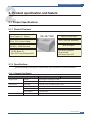
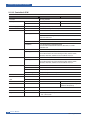

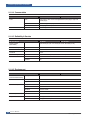
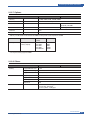
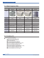
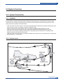

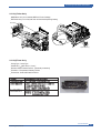
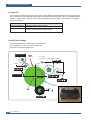
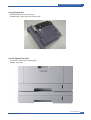


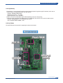

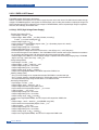
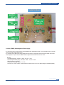


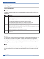

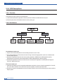
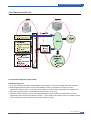
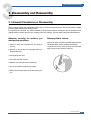
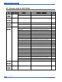
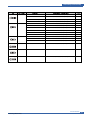

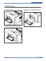
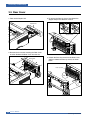
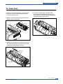


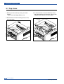
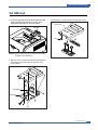
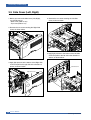
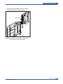

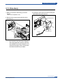


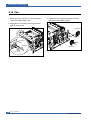

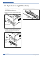
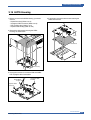
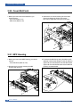


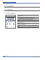

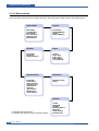
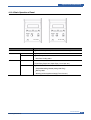


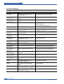


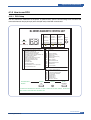
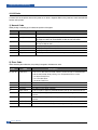
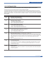
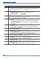
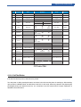
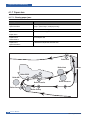

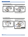
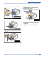

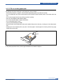
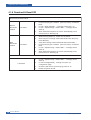

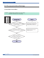

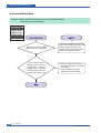
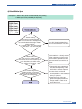

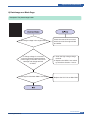
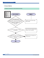

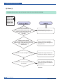
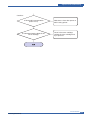
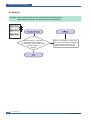
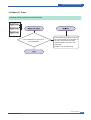

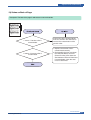
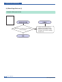
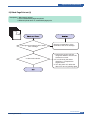

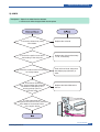
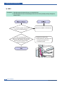
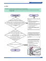
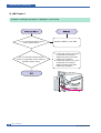
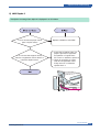
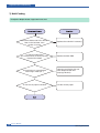

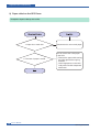


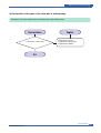
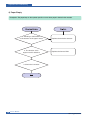
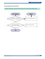
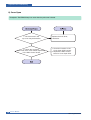

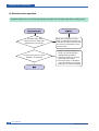


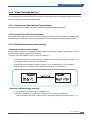
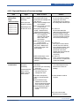


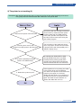
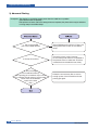
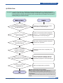
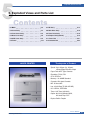
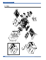
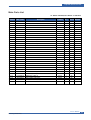
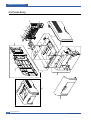

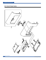


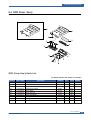
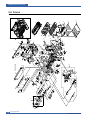


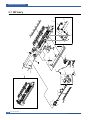
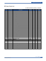

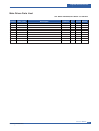
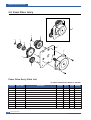

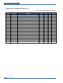
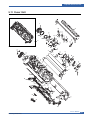
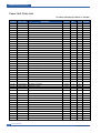


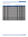

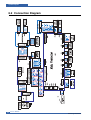

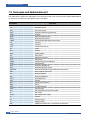
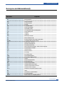

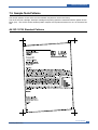
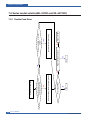
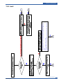
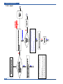
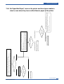
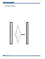


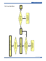
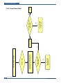


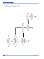

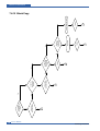
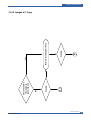

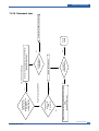
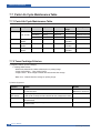

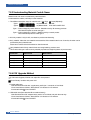


![HomeSullivan 401393BK-24[2PC] Instructions / Assembly](http://vs1.manualzilla.com/store/data/006934915_1-531c68b4e233a29a0ba12108c987ec76-150x150.png)
