1
SPECIFICATIONS
Siting the unit
The Main solar cylinder must be installed vertically.
Although location is not critical, the following points
should be considered:
• The Main solar cylinder should be sited to ensure
minimum dead leg distances, particularly to the point of
most frequent use.
• Avoid siting where extreme cold temperatures will be
experienced. All exposed pipework should be insulated.
• The discharge pipework from the safety valves must
have minimum fall of 1:200 from the unit and terminate in
a safe and visible position.
• Access to associated controls and immersion heaters
must be available to provide for the servicing and
maintenance of the system. Where these controls are
installed against a wall a minimum distance of 250mm
must be left.
• Ensure that the floor area for the Main solar cylinder is
level and capable of permanently supporting the weight
when full of water.
• Wherever possible the mains supply pipe should be
22mm. We suggest the minimum supply requirements
should be 1.5 bar pressure and 20 litres per minute
flow rate.
• The Main solar cylinder has an operating pressure of 3.5
bar which is controlled by the cold water combination
valve assembly. The cold water combination valve
assembly can be connected to a maximum mains
pressure of 16 bar.
Outlet/terminal fittings (taps, etc.)
• The Main solar cylinder can be used with most types of
terminal fittings.
• All fittings, pipework and connections must have a rated
pressure of at least 6 bar at 80°C.
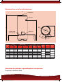
Operational summary
Maximum mains pressure 16 bar
Operating pressure 3.5 bar
Expansion vessel charge pressure 3.5 bar
Expansion relief valve setting 6 bar
T&P relief valve setting 90°C/10 bar
Maximum primary circuit pressure
(auxiliary coil, indirect only) 3 bar
Maximum primary circuit pressure 6 bar (Solar coil)
Important note:
THE MAIN SOLAR CYLINDER MUST BE INCORPORATED
INTO A FULLY PUMPED SOLAR PRIMARY CIRCUIT.
CONTROL OF THE SOLAR PRIMARY IS ACHIEVED BY
THE USE OF EXTERNAL CONTROLS NOT SUPPLIED
WITH THE UNIT. CONTROL MUST BE VIA A PURPOSE
DESIGNED SOLAR HYDRAULIC STATION AND SOLAR
DIFFERENTIAL TEMPERATURE CONTROLLER.
Pipe fittings
All pipe fittings are made via 22mm compression fittings
directly to the unit. The fittings are threaded 3/4” BSP male
parallel should threaded pipe connections be required.
Cold feed
A 22mm cold water supply is recommended, however if a
15mm (1/2”) supply exists which provides sufficient flow
this may be used (although more flow noise may
be experienced).
A stopcock or servicing valve should be incorporated into
the cold water supply to enable the Main solar cylinder and
its associated controls to be isolated and serviced.
Drain tap
A suitable draining tap should be installed in the cold
water supply to the Main solar cylinder unit between
the expansion valve and the heater at as low a level as
possible. It is recommended that the outlet point of the
drain pipework be at least 1 metre below the level of
the heater.
Expansion vessel
The expansion vessel is pre-charged at 3.5 bar and must
be connected between the expansion valve and the Main
solar cylinder.
Secondary circulation
The secondary return pipe should be in 15mm pipe and
incorporate a check valve to prevent backflow. A suitable
WRAS approved bronze circulation pump will be required.
Outlet
Hot water distribution pipework should be 22mm pipe with
short runs of 15mm pipe to terminal fittings such as sinks
and basins.
Installation
Connection to solar primary circuit
The lower (solar) coil of the Main solar cylinder must
be connected to a fully pumped solar primary circuit.
The connections are suitable for 22mm copper pipe direct
to the compression fittings provided. The connections
are also threaded 3/4” BSP male parallel should BSP
be required.
Plumbing connections
Direct units require the following pipework connections.
• Cold water supply to and from inlet controls.
• Outlet to hot water draw off points.
• Discharge pipework from valve outlets to tundish.
• Connection to the auxiliary primary circuit
(Auxiliary/Indirect unit only).
Primary connections are 22mm compression.
However, 3/4” BSP parallel threaded fittings can be
fitted to the primary coil connections if required.
Electrical supply
Main solar units are fitted with 13kW immersion heater
on indirect units and 23kW immersions on direct units as
standard. The Main solar cylinder MUST be earthed.
The circuit must be protected by a suitable fuse and
double pole isolating switch with a contact separation of
at least 3mm in both poles.
18
91529 A4 Main Range Brochure.indd 18
16/05/2014 14:30