1
Chapter 6
Dynamic Range
Definition
Dynamic range is generally thought of as the ability of an analyzer to measure
harmonically related signals and the interaction of two or more signals; for
example, to measure second- or third-harmonic distortion or third-order
intermodulation. In dealing with such measurements, remember that the
input mixer of a spectrum analyzer is a non-linear device, so it always
generates distortion of its own. The mixer is non-linear for a reason. It must
be nonlinear to translate an input signal to the desired IF. But the unwanted
distortion products generated in the mixer fall at the same frequencies as
the distortion products we wish to measure on the input signal.
So we might define dynamic range in this way: it is the ratio, expressed in dB,
of the largest to the smallest signals simultaneously present at the input of
the spectrum analyzer that allows measurement of the smaller signal to a
given degree of uncertainty.
Notice that accuracy of the measurement is part of the definition. We shall
see how both internally generated noise and distortion affect accuracy in the
following examples.
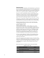
Dynamic range versus internal distortion
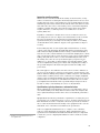
To determine dynamic range versus distortion, we must first determine just
how our input mixer behaves. Most analyzers, particularly those utilizing
harmonic mixing to extend their tuning range1, use diode mixers. (Other
types of mixers would behave similarly.) The current through an ideal diode
can be expressed as:
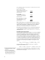
i = Is(eqv/kT–1)
where
IS = the diode’s saturation current
q = electron charge (1.60 x 10⁻¹⁹ C)
v = instantaneous voltage
k = Boltzmann’s constant (1.38 x 10⁻²³ joule/°K)
T= temperature in degrees Kelvin
We can expand this expression into a power series:
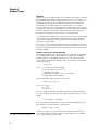
i = Is(k1v + k2v2 + k3v3 +...)
where
k1 = q/kT
k2 = k12/2!
k3 = k13/3!, etc.
Let’s now apply two signals to the mixer. One will be the input signal that
we wish to analyze; the other, the local oscillator signal necessary to create
the IF:
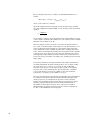
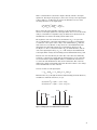
v = VLO sin(ωLOt) + V1 sin(ω1t)
If we go through the mathematics, we arrive at the desired mixing product
that, with the correct LO frequency, equals the IF:
k2VLOV1 cos[(ωLO – ω1)t]
1. See Chapter 7, “Extending the Frequency Range.”
70
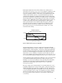
A k2VLOV1 cos[(ωLO + ω1)t] term is also generated, but in our discussion
of the tuning equation, we found that we want the LO to be above the IF, so
(ωLO + ω1) is also always above the IF.