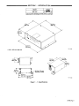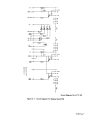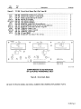
1
Y8y7?~i
IMPORTANT: Read and understand the entire
contents of both this manual and the power source
manual used with this unit, with special eutiphasis
on the safety material throughout both manuals,
before installing, operating, or maintaining this
equipment. This unit and these instructions are for
use only by persons trained and experienced in the
safe operation of welding equipment. Do not allow
untrained persons to install, operate, or maintain
this unit. Contact your distributor if you do not fully
understand these instructions.
OWN ER’S
MANUAL
Effe~ti. E With SanE I Fic.
ADDITIONAL COPY PRICE 95 CENTS
NWSA CODE NO. 4579
PRINTED IN U S A
H1:33:~’ I
MODEL
MR-5/ARC PAKTM 350
COMPUTER INTERFACE
GAS/CURRENT SENSING
CONTROL
+5
millER
MILLER ELECTRIC MFG. Co.
718 S BOUNDS ST, P 0 Box 1079
APPLETON, WI 54912 USA
..
LIMITED WARRANTY
EFFECTIVE: OCTOBER 1, 1986
4;
4;
4;
4!
4;
4;
~Ji
4~<
~
This warranty supersedes all previous MILLER warranties and is exclusive with no other guarantees or warranties expressed or implied
LIMITED WARRANTY Subject to the terms and conditions hereof, Miller Electric Mfg. Co., Appleton, Wisconsin
warrants to its Distributor/Dealer that all new and unused
Equipment furnished by Miller is free from defect in workmanship and material as of the time and place of delivery by Miller.
No warranty is made by Miller with respect to engines, trade
accessories or other items manufactured by others. Such
engines, trade accessories and other items are sold subject to
the warranties of their respective manufacturers, if any . All
engines are warranted by their manufacturer for one year from
date of original purchase, except Tecumseh engines which
have a two year warranty.
Except as specified below, Miller’s warranty does not apply
to components having normal useful life of less than one Ill
year, such as spot welder tips, relay and contactor points,
MILLERMATIC parts that come in contact with the welding
wire including nozzles and nozzle insulators where failure does
not result from defect in workmanship or material.
Miller shall be required to honor warranty claims on warranted Equipment in the event of failure resulting from a defect
within the following periods from the date of delivery of Equipment to the original user:
1. Arc welders, power sources, robots, and components . 1 year
2. Load banks
1 year
3. Original main power rectifiers
3 years
Ilabor - 1 year onlyl
4. All welding guns, feeder/guns and plasma torches... 90 days
All other Millermatic Feeders
1 year
Replacement or repair parts, exclusive of labor .. 60 days
7. Batteries
6 months
provided that Miller is notified in writing within thirty 1301 days
of the date of such failure.
As a matter of general policy only, Miller may honor claims
submitted by the original user within the foregoing periods.
In the case of Miller’s breach of warranty or any other duty
with respect to the quality of any goods, the exclusive remedies
therefore shall be, at Miller’s option (11 repair or 121 replacement
or, where authorized in writing by Miller in appropriate cases, (3)
the reasonable cost of repair or replacement at an authorized
Miller service station or 14) payment of or credit for the purchase
price (less reasonable depreciation based upon actual usel upon
return of the goods at Customer’s risk and expense. MILLER’s
option of repair or replacement will be FOB., Factory, at
Appleton, Wisconsin, or FOB., at a MILLER authorized service
facility, therefore, no compensation for transportation costs of
any kind will be allowed. Upon receipt of notice of apparent
defect or failure, Miller shall instruct the claimant on the warranty
claim procedures to be followed.
ANY EXPRESS WARRANTY NOT PROVIDED HEREIN AND
ANY IMPLIED WARRANTY, GUARANTY OR REPRESENTA•flON AS TO PERFORMANCE, AND ANY REMEDY FOR
BREACH OF CONTRACT WHICH, BUT FOR THIS PROVISION,
MIGHT ARISE BY IMPLICATION, OPERATION OF LAW,
CUSTOM OF TRADE OR COURSE OF DEALING, INCLUDING
ANY IMPLIED WARRANTY OF MERCHANTABILITY OR OF
FITNESS FOR PARTICULAR PURPOSE, WITH RESPECT TO
ANY AND ALL EQUIPMENT FURNISHED BY MILLER IS EXCLUDED AND DISCLAIMED BY MILLER.
EXCEPT AS EXPRESSLY PROVIDED BY MILLER IN
WRITING, MILLER PRODUCTS ARE INTENDED FOR
ULTIMATE PURCHASE BY COMMERCIAL/INDUSTRIAL
USERS AND FOR OPERATION BY PERSONS TRAINED AND
EXPERIENCED IN THE USE AND MAINTENANCE OF
WELDING EQUIPMENT AND NOT FOR CONSUMERS OR
CONSUMER USE. MILLER’S WARRANTIES DO NOT EXTEND
TO, AND NO RESELLER IS AUTHORIZED TO EXTEND
MILLER’S WARRANTIES TO, ANY CONSUMER.
May 31,1990
~OM.882j
ERRATA SHEET
After this manual was printed, refinements In equipment design occurred. This sheet lists exceptions
to data appearing later in this manual.
AMENDMENT TO SECTION 2— INSTALLATION
IMPORTANT: A 25 ft. (8m) interconnecting cord with a five-pin Amphenoiplug is supplied with this unit but is not used
in this installation. Retain cord for future use.
Add the foliowing IMPORTANT block to the end of Section 2-3A. COMPUTER INTERFACE WELDING POWER
SOURCE CONNECTIONS: Wire Stick Sensing Connections
-
IMPORTANT: If dc electrode negative welding is desired, reverse connections so the lead with ring terminal is
connected to the negative weld output terminal and the lead with a clamp is connected to the positive weld output
terminal.
Amend Section 2-3C. COMPUTER INTERFACE
AC/Contactor Control Connection
-
WELDING POWER SOURCE CONNECTiONS: 115 Volts
IMPORTANT: Cords are supplied that may not be used in this installation. Match cord to welding power source and
computer interface available.
1.
Align keyways, insert 4-socket Amp plug into matching receptacle on computer interface, and rotate threaded
collar fully clockwise.
2. Align keyway, insert 14-pin Amphenol plug into matching receptacle on welding power source, and rotate
threaded collar fully clockwise.
3. Place appropriate remote control switch(es) on the welding power source in the proper position for use of a
remote control device.
Amend Section 2-5. COMPUTER INTERFACE TERMINAL STRIP CONNECTIONS
A
WARNING: ELECTRIC SHOCK can kill.
Do not touch live electrical parts.
0
Shut down unit, welding powersource, and robot, and disconnect inputpoweremploying lockout/tagging procedures before making interconnections.
Lockout/tagging procedures consist of padlocking line disconnect switch in open position, removing fuses
from fuse box, or shutting off and red-tagging circuit breaker or other disconnecting device.
There are several terminal strips inside the computer interface for control connections. Remove unit top cover, loosen
screws on strain relief on unit rear panel if necessary, and locate appropriate terminal strip for connections. Tighten
screws on strain relief if necessary, and reinstall top cover when procedure is finished.
0
A. CVICC Connections
A
1.
2.
WARNING: Read and follow safety information at beginning of Section 2-5 before proceeding.
Locate terminal Strip 2T.
For CC operation, remove jumper link between terminal E and F on 2T.
IMPORTANT: The Inductance control is disabled when operating in the CC (constant current) mode.
B. ARC FAILURE Light Connections (Figure 2-4)
A
WARNING: Read and follow safety Information at beginning of Section 2-5 before proceeding.
The ARC FAILURE lightorlthe computerinterface front panel is turnedon and off by a signalfromthe robot control unit.
Locate supplied length of 18 gauge/2-conductor cord for this connection, and proceed as follows:
1. For robot control units with no other connections at jig terminal strip 2:
a. Open robot control unit door, and locate jig terminal strip 2.
b. Route cord under cross member below door.
c. Make cord connections to terminal strip common and the Weld Alarm terminal.
d. Close robot control unit door, and route cord through strain relief on rear panel of computer interface.
e. Connect cord to 2TF and 2TG.
2. For robot control Units when 115 or 24 vac, or 24 vdc is used at jig terminal strip 2T:
a. Obtain a 115 or 24 vac, or 24 Vdc isolation relay, and install into jig interface.
b. Open robot control unit door, and locate jig terminal strip 2.
c. Route customer supplied 18 gauge/2-conductor cord under cross member below door.
d. Make cord connections to terminal strip common and the Weld Alarm terminal.
e. Close robot control unit door, and route cord to jig interface.
f. Connect cord to isolation relay coil and voltage source.
g. Cut off terminals from one end of supplied 18 gauge/2-conductor cord, and install terminals to connect to
contacts on isolation relay.
h. Connect one end of cord to a set of normally-open contacts on isolation relay.
i. Route cord through strain relief on rear panel of computer interface.
j. Connect cord to 2TF and 2TG.
OM-882 Page 2
Add Figure 2-4. Arc Failure Light Connections
Jig Terminal
Strip 2
Computer Interface
2TF
+24VDC
Common
Robot
control
2TG
Unit
weld Alarm
Arc Failure
2TL
Indicator
Light
To Voltage Source
(115VAC, 24VAC, 24VDC)
-rj 2TF
~—
Robot
Control
Unit
Arc Failure
Indicalor
Weld
Alarm
Jig Interface
Light
TA-il5 648
Figure 2-4. Arc Failure Light Connections
AMENDMENT TO SECTION 5- MAINTENANCE & TROUBLESHOOTING
Add the following Step to Section 5-1 INSPECTION AND UPKEEP
3. Inspect motor control relay, CR2, and clean or replace as required.
-
Amend Figure 5-3. Circuit Diagram For Computer Interface (see Page 4 on this Errata)
Amend Figure 5-4. Circuit Diagram For Voltage Control Board PCi (see Page 5 on this Errata)
Amend Figure 5-6. Circuit Diagram For Interface Board PC3 (see Page 6 on this Errata)
Add Figure 5-9. Wiring Diagram (see Pages 7 and 8 on this Errata)
OM-882 Page 3
AMENDMENT TO SECTION 5
-
MAINTENANCE & TROUBLESHOOTING
Amend Figure 5-3. Circuit Diagram For Computer Interface
000
U
K
0~
000000
U
N
k~,
~000
-
K
~
-,
-~
C0CWL.~CI~N
00 0 0 0 0 0
=0CL,Lt,~tj7~~liU
C
d
z
~
E
Cu
0
(3
cc
to
0
C~J
6
z
w
U
0)
0)
U
0)
0)
‘N
S~~CNN
0.
E
0
C.)
I0
U-
E
I-
0)
N.FS
0
SN-CCN(
srNso~
I..
(3
JOG ~EV
~
~
0)
1~
ci
9E’EC’
Ua’AGE
OM-882 Page 4
-
a
I
C.’J
to
C~4
1~
6
6
z
ECu
Cu
o
—
o
(3-,
•~‘
to
to
.~
U,
6
z
1~
0)
C/)
0)
0
0)
w
50.
•0
ICu
0
3
0
C.)
0)
C)
Cu
3
I-
0
IL
ECu
I-
C)
Cu
4
U
I-
(3
0)
C)
OM-882 Page 5
5V
,24V
06
AR
4ELD START
AL
CR
JOG
F~C
2
C ON-S
REF EEC
ACTOR
CR5
WELD
AL
CURRENT
RELA’ AJ
JOG (RE.
~
A
6050’
CJRRE’.’
CEC XCT
RE.. RE.A’
4
CR4
CON’N-C’CR
AC
Circuit Diagram No. B-128 016-A
FIgure 5-6. CIrcuit Diagram For interface Board PC3 Effective With Serial No. JK588314 Thru KA819026
‘LO
A
‘24
CC
AC
.24 C.
6
06
~ELC S’ART
UDO
(L(~fl(
AR
AE
—
CR
6
045
RELO
CURRENT
RELAY
406
(RE6I
AL
A.
A
T
C07R40N,
REV.
RELAX
C SE L FEC
AC’CR
C66
OR?
6080’
CL PRE N
CECEO C
CR4
0C7,’4C’CR
ALA
1<
AC
Circuit Diagram No. B-i 37 905
Figure 5-6.Circuit Diagram For interface Board PC3 Effective With Serial No. KABi 9027
OM-882 Page 6
Add Figure 5-9. Wiring Diagram
cc
r-.
I”1~
‘N
0
6
E
Cu
z
C)
0
C)
cc
U,
to
to
1..
I-
cc
to
0
c,,J
6
z
h..
0)
U)
0)
C.)
0)
w
E
Cu
I..
C)
Cu
0
C)
C
U,
0)
C)
ir
OM-882 Page 7
c~J
1~
6
E
Cu
z
I-
C)
0
C
to
U,
to
to
6
2
I-
0)
U)
0)
0)
w
ECu
C)
0
C
0)
L..
OM-e82 Page 8
AMENDMENT TO PARTS LIST
Amend Parts List as follows:
Part
Replaced
2-1
111 992
117 724
2-1
2-4
117724
129 952
CONTROL PANEL, (Elf w/JH290689 thru
JK636568)
CONTROL PANEL, (Effw/JK636569)
070 634
123 154
LABEL, warning general precautionary
049 989
604 109
028 291
090 890
iii 564
011 622
Added
118 676
604 109
028 291
135 304
117836
011 609
110 438
8-
044 635
083 147
035 914
034 841
110375
111 065
111 408
113 221
128014
073 730
073 739
048 284
079 534
079 531
604 571
iii 122
109 770
030 028
083 147
035 704
109 006
110375
121 313
131 247
128 014
128014
073 730
073 739
8-
000 885
000 88S
Added
049 015
072 130
072 130
072 130
005023
073 739
Deleted
Deleted
073739
028 3S1
109 936
079682
010 610
028351
117 617
136 59S
115 104
110386
117725
117 726
CABLE, volt sensing (Eff w/HJ304076)
WIRE, (qty chg)
CAPACITOR, (qty chg)
CABLE, port No. 18 8/c (order by ft)
CIRCUITOARD, meter
SWITCH, tgl SPDT iSA 125V
CABLE, interconnecting 25ft (Eff w/JK678982)
(consisting of)
HOUSING PLUG & SOCKETS, (consisting of)
TERMINAL, female iskt 14-18w
CLAMP, cable strain relief sz 11
CABLE, port No. 184/c (order by ft)
HOUSING PLUG & PINS, (consisting of)
TERMINAL, female 1 pin sz 45 16-22w
RESISTOR, C .5W 1.5K ohm
GROMMET, (qty chg)
RECTIFIER, (qty chg) integ 30A 600V
RELAY, end 24VAC DPDT (Effw/JK636569)
STANDOFF, (qtychg)
PANEL, rntg-components (Elf w/JJ377225)
CIRCUIT CARD, Voltage control (Effw/JK655454)
CIRCUIT CARD, interface (Effw/JK588314)
CIRCUITCARD,interface, (Effw/KA819027)
TERMINAL, hdr 22 pin
CAPACITOR, (qty chg added C25-30)
(EU w/JK655454)
RESISTOR, (qty chg added R46,47)
(Elf w/JK655454)
RESISTOR, CF .25W 10 meg ohm
(Eff w/JK655454)
CAPACITOR, (qty chg deleted C6, 9, 10)
(Elf w/JK588314 thru KA819026)
Elf w/KA819027
Elf w/KA819027
CAPACITOR (qty chg deleted Cli
(Elf w/ JK5883 14)
DIODE, (qty chg added D16) (Elf w/JK588314)
CONTROL BOX, gas/current sensor
RELAY,current
CONNECTOR CLAMP, cable 1/2 in
RELAY,encI24VACDPDT
TRANSFORMER,control
CAPACITOR/RESISTOR, (consisting of)
Dia.
Mkgs
2-17
2-20
22-39
2-48
C2,3,6-10
3-56
3-
51
PC4
46-2
Ri-S
6-5
6-12
6-15
6-16
SR1,2
CR1
6-25
6-26
6-26
6-28
8-
PCi
PC3
PC3
RC5
R48,49
11—
11—
11-
C3
C4
11-
11—
13-
13-3
13-6
REED
CR5
Ti
No.
Description
With
.
.
Quantity
1
1
1
1
2 6ft
7
61 t
1
1
1
1
4
1
25ft
1
14
1
2
2
1
7
1
1
1
1
1
25
ii
2
OM-582 Page 9
Parts Lists Continued
C4,S
R4
1313-
Added
Added
000 859
601 394
136584
007501
• CAPACITOR, eIctlt 220uf 35VDC
•RESISTOR,C2WlOKohm
BRACKET, mtg reed relay
WASHER, flat nyl .265 ID x .437 OD
~First digit represents page no digits following dash represent item no.
BE SURE TO PROVIDE MODEL AND SERIAL NUMBER WHEN ORDERING REPLACEMENT PARTS.
-
OM-882 Page 10
2
1
2
TABLE OF CONTENTS
Section No.
SECTION 1
1
1
I
-
-
Page No.
INTRODUCTION
1. General Information And Safety
2. Receiving-Handling
3. Description
SECTION 2
-
2-1.
2 2.
2 3.
2 4.
2 5.
-
-
-
-
-
SECTION 3
3-1.
3 2.
3 3.
3 4.
3-5.
3 6.
3 7.
-
-
-
SECTION 4
-
-
5
5
5
5
5
-
1.
2.
3.
4.
5.
-
6
6
6
6
6
6
6
SEQUENCE OF OPERATION
4 1. input Signal From Welding Power Source
4 2. Output Signals From Computer Interface
4-3. Wire Stick Check
SECTION 5
2
3
3
4
5
FUNCTION OF CONTROLS
PowerSwitch
Inductance Control
Overload Protection
Voltmeter
WireSpeedMeter
Ammeter
Indicator Lights
-
2
2
INSTALLATION
Location
Gas/Current Sensing Control Connections
Computer Interface Welding Power Source Connections
Computer Interface Welding Power Source Interface Connections.
Computer Interface Terminal Strip Connections
-
2
6
7
7
MAINTENANCE 8 TROUBLESHOOTING
Inspection And Upkeep
Overload Protection
Display Board Meter Check
Board Replacement Procedures
Troubleshooting Chart
7
7
8
8
10
SECTION 1
-
INTRODUCTION
Model
II
+ 16.5
Weight
31 lbs. (14 kg)
MR-5AP
Gas/Current Sensing Control 5 lbs. (2.3 kg)
TB-i 14346
in. (419 minI case only
2-7/8 in.
(73.0 minI
In.
mm)
16 in. (7.9 mm)
Diameter 2 Holes
TB-i 10320
Figure 1
-
1. Specifications
OM-882 Page 1
1
1. GENERAL INFORMATION AND SAFETY
-
carefully followed could result in minor personal injury
or damage to this equipment.
A. General
A third signal word,
•s•s,
highlights instructions which need special emphasis to obtain the most
Information presented in this manual and on various
labels, tags, and plates on the unit pertains to equipment design, installation, operation, maintenance, and
troubleshooting which should be read, understood, and
followed for the safe and effective use of this equipment.
efficient operation of this equipment.
1 2. RECEIVING-HANDLING Before installing
this equipment, clean all packing material from around
the unit and carefully inspect for any damage that may
have occurred during shipment. Any claim for loss or
damage that may have occurred in transit must be filed
by the purchaser with the carrier. A copy of the bill
of lading will be furnished by the manufacturer on request if occasion to file claim arises.
-
B. Safety
The installation, operation, maintenance, and
troubleshooting of arc welding equipment requires
practices and procedures which ensure personal safety
and the safety of others. Therefore, this equipment is to
be installed, operated, and maintained only by qualified
persons in accordance with this manual and all applicable codes such as, but not limited to, those listed at
the end of Section 1 Safety Rules For Operation Of
Arc Welding Power Source in the welding power source
Owner’s Manual.
-
When requesting information concerning this equipment, it is essential that Model Description and Serial
Number of the equipment be supplied.
1 3. DESCRIPTION The computer interface control contains wire feed speed, weld voltage, and weld
amperage control circuitry, digital ammeter, voltmeter,
and wire feed speed meter, and circuitry to interface
with the robot control. The control is shipped for operation in the constant voltage mode but has constant current capabilities.
-
-
Safety instructions specifically pertaining to this unit appear throughout this manual highlighted by the signal
words WARNING and CAUTION which identify
different levels of hazard.
-
The gas/current sensing control contains the gas valve
and current sensing reed relay.
WARNING statements include installation, operation,
and maintenance procedures or practices which if not
These components function with the robot system
when using the Gas Metal Arc Welding (GMAW) process.
carefully followed could result in serious personal injury
or loss of life.
CAUTION statements include installation, operation,
and maintenance procedures or practices which if not
SECTION 2
2
-
-
INSTALLATION
1. LOCATION (Figure 1-1)
The location should allow room to open and remove
covers and wrappers for installation, maintenance, and
repair. Lead lengths must be considered when locating
components.
Mounting holes are provided in each component for
mounting purposes. Figure 1-1 gives unit dimensions.
Wire Stick Sensing
Strain
Receptacle RC12 Inductance Relief
control
Welding Power Source
Interface Receptacle
Voltage control
RC17
Receptacle RC13
Normally the computer interface is mounted on top of
the robot control unit. The gas/current sensing control
should be mounted in line between the welding power
source and wire drive assembly. See installation section
of robot manual for specific information.
The service life and efficiency of the system are reduced
when it is subjected to high levels of dust, dirt,
moisture, corrosive vapors, and extreme heat.
Gas/current Sensing
control Receptacle RC9
115 Volts Ac/contactor
control Receptacle Rd 1
re-114 347
Figure 2
OM-882 Page 2
-
1. Rear Panel View
2 2. GAS/CURRENT SENSING CONTROL CONNECTIONS (Figures 2-1 And 2-2)
D. Gas Connections
-
ELECTRIC SHOCK can kill.
• Do not touch live electrical parts.
• Shut down unit, welding power source, and
robot, and disconnect input power employing
“lockout/tagging procedures” before making interconnections.
Lockout/tagging procedures consist of padlocking line
N-.
Connect hose from gas regulator/flowmeter (customer
supplied) at gas source to IN fining on gas/current sensing control. Connect gas hose from wire drive
assembly to fitting on gas/current sensing control. The
gas flow must be accurately controlled by a
regulator/flowmeter at the source.
E. Touch Sensor Connections
disconnect switch in open position, removing fuses
from fuse box, or shutting off and red-tagging circuit
Connect cord with two friction connectors coming from
gas/current sensing control to touch sensor leads coming from outlet cable. Polarity is not important for this
breaker or other disconnecting device.
A. Computer Interface Gas/Current Sensing
Control Connections
connection.
1. Align keyways, insert 14-pin Amp plug into mat-
2 3. COMPUTER INTERFACE
WELDING
POWER SOURCE CONNECTIONS (Figures 2-1 And
2-2)
-
-
ching receptacle on computer interface, and
rotate threaded collar fully clockwise.
2. Align keyways, insert 16-pin Amp plug into matching receptacle on gas/current sensing control,
and rotate threaded collar fully clockwise.
B. Gas/Current Sensing Control
nections
-
Motor Con-
•
•
-
ELECTRIC SHOCK can kill.
Do not touch live electrical parts.
Shut down unit, welding power source, and
robot, and disconnect input power employing
“lockout/tagging procedures” before making interconnections.
Lockout/tagging procedures consist of padlocking line
Align keyways, insert 14-pin plug from motor into matching receptacle on gas/current sensing control, and
rotate threaded collar fully clockwise.
disconnect switch in open position, removing fuses
from fuse box, or shutting off and red-tagging circuit
breaker or other disconnecting device.
There are several cords used for interconnections bet-
C. Weld Cable Connections
Route cable from welding power source positive weld
output terminal, through the gas/current sensing control, to the wire drive assembly and connect cable to
weld cable terminal (see Motor/Drive Assembly
Owner’s Manual for location).
ween the computer interface and welding power
source. Examine and select the proper cord for the
following connections.
115 Volts AC/Contactor
Computer
control Cord
Arc Pak Welding
Interface
Power Source
RC17 Rd
Sensor
GaslCurrent
Sensing Control
Arc Failure
Connection In
Robot Control UnIt
Motor ControlCord
TB-i 14 357
Figure 2
-
2. Interconnection Diagram
OM-882 Page 3
2. Connect the twistlock receptacles to the matching plugs, and rotate plugs clockwise.
A. Wire Stick Sensing Connections
1. Align keyway, insert four-socket Amphenol plug
into matching receptacle on computer interface,
and rotate threaded collar fully clockwise.
2. Connect lead with ring terminal to welding
power source positive output terminal.
3. Connect lead with clamp to welding power
source negative output terminal.
B. Voltage Control Connections
1. Align keyway, insert 17-socket plug into matching receptacle on computer interface, and
rotate threaded collar fully clockwise.
2. Align keyway, insert 17-pin plug into matching
receptacle on welding power source, and rotate
threaded collar fully clockwise.
C. 115 Volts AC/Contactor Control Connections
Two cords are necessary for this connection. One cord,
supplied with the welding power source, has a 14-pin
Amphenol plug and two twistlock receptacles. The second, supplied with the robot, has two twistlock plugs
and a four-pin Amp plug.
1. Align keyways, insert four-pin Amp plug into
matching receptacle on computer interface, and
rotate threaded collar fully clockwise.
3. Align keyway, insert 14-pin Amphenol plug into
matching receptacle on welding power source,
and rotate threaded collar fully clockwise.
2 4. COMPUTER INTERFACE
WELDING
POWER SOURCE INTERFACE CONNECTIONS
(Figures 2-1, 2-2, And 2-3)
-
-
WARNING: ELECTRIC SHOCK can kill.
• Do not touch live electrical parts.
• Shut down unit, welding power source, and
robot, and disconnect input power employing
‘lockout/tagging procedures” before making interconnections.
Lockout/tagging procedures consist of padlocking line
disconnect switch in open position, removing fuses
from fuse box, or shutting off and red-tagging circuit
breaker or other disconnecting device.
1. Align keyway, insert 24-socket plug into matching receptacle on computer interface, and
rotate threaded collar fully clockwise.
2. Align keyways, insert four-, six-, and ten-pin
plugs from interconnecting cord into matching
receptacles on bottom of welding power source
interface, and rotate threaded collars fully
clockwise.
Power Source
Welding
Current
(WCR) Detect
Figure 2
OM-882 Page 4
-
3. Welding Power Source Interface Connections
3. Remove welding power source interface side
panel.
4. Route remaining cord from computer interface
through strain relief in bottom of welding power
source interface, to 14-position terminal strip.
A. ARC FAILURE Light Connections
5. Connect leads as follows:
a.
The ARC FAILURE light on the computer interface front
panel is turned on and off by a signal from the robot
control unit. The robot control unit must supply 24 volts
dc to the computer interface arc failure circuit when arc
failure occurs. Locate supplied length of 18 gauge/2
conductor cord for this connection, and proceed as
follows:
Red lead to terminal 52.
b. Blue lead to terminal 50.
c.
There are several terminal strips inside the computer interface for control connections. Remove unit top cover,
loosen screws on strain relief on unit rear panel if
necessary, and locate appropriate terminal strip for connection. Tighten screws on strain relief if necessary,
and reinstall top cover when procedure is finished.
White lead to terminal 35.
d. Green lead to terminal 36.
e. Long green lead with ring terminal connects
to chassis ground.
6. Reinstall and secure side panel.
1. Open robot control unit door, and locate jig terminal strip 2.
2. Route cord under cross member below door.
2 -5. COMPUTER INTERFACE TERMINAL STRIP
CONNECTIONS
3. Make cord connections to terminal strip common and the Weld Alarm terminal.
IMPORTANT: A 25 ft. (8m) interconnecting cable
with a five-pin Amphenol plug is supplied with this unit
but is not used in this installation. Retain cable for
future use.
4. Close robot control unit door, and route cord
through strain relief on rear panel of computer interface.
5. Connect cord common to 2TL and positive to
WARNING: ELECTRIC SHOCK can kill.
• Do not touch live electrical parts.
• Shut down unit, welding powersource, and robot
and disconnect input power employing
“lockout/tagging procedures” before making interconnections.
Lockout/tagging procedures consist of padlocking line
disconnect switch in open position, removing fuses
from fuse box, or shutting off and red-tagging circuit
breaker or other disconnecting device.
SECTION 3
-
2TG.
B. CV/CC Connections
1. Locate terminal strip 2T.
2.
For CC operation, remove jumper link between
terminals E and F on 2T.
IMPORTANT: The Inductance control is disabled
when operating in the CC (constant current) mode.
FUNCTION OF CONTROLS
Arc Failure
indicator
Light
Figure 3
-
Ta-i 14 436
1. Front Panel View
OM-882 Page 5
3
3 4. VOLTMETER (Figure 3-1)
The voltmeter displays weld voltage to the nearest tenth
1. POWER SWITCH (Figure 3-1)
-
-
Placing the POWER switch in the ON position applies
input power to the interface. The interface must be on
for the robot to weld. Placing the POWER switch in the
OFF position shuts down the interface.
3 -2. INDUCTANCE CONTROL (Figure 2-1)
The INDUCTANCE control is a digital pushbutton control which can be set for inductance levels 1 through 7.
As the level of inductance increases, the rate of change
of the weld output or speed of response slows down.
The slower response time produces a softer arc, more
fluid welding puddle, and flatter, smoother bead.
The 0 (zero) setting gives minimum inductance, i.e., a
stiff, fast-responding arc, and a small, fast-freezing
puddle. The 7 setting gives maximum inductance
characteristics, i.e., a soft, slow-responding, low spatter arc, and high weld puddle fluidity.
-
3. OVERLOAD PROTECTION (Figure 3-1)
A. Fuse Protection
The interface is protected from damage due to an internal short or excessive overload by fuse Fl. If fuse Fl
opens, the interface shuts down. See Section 5-2 for
replacement procedures.
B. Wire Drive Motor Circuit Breaker
The wire drive motor is protected from damage due to
overload by circuit breaker CB1. If CB1 opens, the interface shuts down. Manually depress the reset button to
reset the circuit breaker.
SECTION 4
-
3 -5. WIRE SPEED METER (Figure 3-1)
The wire speed meter displays preset wire feed speed to
the nearest inch per minute while welding and idling.
Actual and preset wire feed speed are the same due to
the wire feed speed feedback circuit.
3
-
6. AMMETER (Figure 3-1)
The ammeter displays weld amperage to the nearest
amp while welding and preset amperage while idling.
3
-
7. INDICATOR LIGHTS (Figure 3-1)
There are five indicator lights on the interface. These
are visual indications of various process functions.
The GAS light turns on when the gas valve is energized
to indicate shielding gas flow.
Select a setting best suited for the application.
3
of a volt while welding and preset voltage while idling.
The CONTACTOR light turns on when the welding
power source contactor is energized to indicate that
weld output is available.
The WIRE FEED light turns on when the wire drive
motor is energized to indicate that wire is feeding.
The CURRENT light turns on when the current detect
relay is energized to indicate that an arc is established.
The ARC FAILURE light turns on when there is an arc
outage while welding.
SEQUENCE OF OPERATION
Arc Initiation
4 -1. INPUT SIGNAL FROM WELDING POWER
SOURCE (Figure 4-1) The welding power source
and wire drive motor send signals to the computer interface. These signals are used to determine weld
parameters. During welding these signals are compared
to preset welding values and compensations are made
to keep weld parameters at preset levels.
Welding Current
-
No-Load
WeldingT~
Voltage
0 to 50V
H-
Crater
—F
WeldAbnormal
D~LY
—
Open when abnormality occurs.
Time
Start
TA-i 14 379
Figure 4
OM-882 Page6
-
1. Input Signal Timing Chart
4 2. OUTPUT SIGNALS FROM COMPUTER INTERFACE (Figure 4-2) The interface interprets the
input signals from the welding power source, wire drive
motor, robot, and wire stick check circuit. The output
of the computer interface regulates the welding power
source and wire feed functions while welding.
-
-
I
Close
~~chlng~
5VDC
I
I
I
TA~1 14 379
I
Figure 4
Output To Motor
-
3. Wire Stick Check
If the feedback indicates the wire is stuck, the welding
power source is sent a 1 .25 VDC command signal to
provide minimum welding power source output. The
contactor is pulsed on. If the wire was stuck, the pulsed
voltage should be enough to free the wire. Feedback is
used to determine if the wire is now free of the weld. If
the feedback indicates the wire is free, the robot can cycle to its next sequence.
Start
TA-i 14 378
Figure 4
-
2. Output Signal Timing Chart
4 3. WIRE STICK CHECK (Figure 4-3) After the
weld is completed, the wire stick check is performed to
determine if the welding wire has burned back out of
the weld puddle.
-
-
Feedback is used to determine if the wire is free of the
weld. If the feedback indicates the wire is free of the
weld, the robot can cycle to its next sequence.
SECTION 5
-
If the feedback indicates the wire is still stuck, a higher
voltage command is given, and the contactor pulsed to
free the welding wire. The check is performed and two
more voltage increases are used to try and free the
welding wire (see Figure 4-3).
If the wire remains stuck, the robot will shut down, a
Weld Abnormal error will be displayed on the robot program module, and the wire must be physically removed
from the weld.
MAINTENANCE & TROUBLESHOOTING
•~j~j~~j5 Every six months inspect the labels on
this unit for legibility. All precautionary labels must be
maintained in a clearly readable state and replaced
when necessary. See the Parts List for part number of
precautionary labels.
-
I
Voltage 1 .25VDC
Command
Open
I
5
I
I
2.5VDC
Arc Initiation
Close
Open
Wire Start Relay
1OVDC
1. INSPECTION AND UPKEEP
WARNING: ELECTRIC SHOCK can kill.
• Do not touch live electrical parts.
• Shut down unit, welding powersource, and robot
and disconnect input power employing
‘lockout/tagging procedures” before internally
inspecting or servicing.
Lockout/tagging procedures consist of padlocking line
disconnect switch in open position, removing fuses
from fuse box, or shutting off and red-tagging circuit
breaker or other disconnecting device.
Usage and shop conditions will determine the frequency
and type of maintenance. Inspect equipment as follows:
1. Repair or replace, as required, all hoses, cords,
and cables; give particular attention to frayed
and cracked insulation and areas where it enters
equipment.
2. Remove grease and grime from components;
moisture from electrical parts and cables.
5 2. OVERLOAD PROTECTION (Figure 3-1)
-
WARNING: ELECTRIC SHOCK can kill.
• Do not touch live electrical parts.
• Shut down unit, welding power source, and robot
and disconnect input power employing
“lockout/tagging procedures” before internally
inspecting or servicing.
Lockout/tagging procedures consist of padlocking line
disconnect switch in open position, removing fuses
from fuse box, or shutting off and red-tagging circuit
breaker or other disconnecting device.
OM-882 Page 7
Figure 5
-
1. Display Board Meter Checks
CAUTION: IMPROPER FUSES can damage this
unit.
If replacement becomes necessary, use only fuses
of the proper size, type, and rating (see Parts
List).
3. Check voltage according to Figure 5-1.
4. If a meter power supply and command voltage is
correct and the meter is not working, replace the
meter (see Section 5-4).
5. If the power supply or command voltage is incorrect, replace display board PC4 (see Section
5-4).
To replace the fuse, proceed as follows:
1. Depress and rotate fuse
counterclockwise.
holder cover
2. Pull out fuse with cover when fuse holder cover
is free.
3. Insert new fuse into fuse holder cover.
4. Install fuse with fuse holder cover back into unit.
5. Depress and rotate fuse holder cover clockwise
until cover is secure.
5 3. DISPLAY BOARD METER CHECK (Figure
5-1) Check points are provided on the display board
for checking power supply and input command for the
meters.
-
-
~
•
•
ELECTRIC SHOCK can kill.
Do not touch live electrical parts.
Be sure that personnel performing testing procedures are familiar with and follow standard safety practices.
• Shut down unit before making or changing meter
or test equipment lead connections.
ELECTROSTATIC DISCHARGE (ESD) can damage
electronic components.
• Put on a properly grounded wrist strap BEFORE
handling circuit boards.
• Transport all static-sensitive components in proper static-shielding carriers and packages.
• Perform work only at a static-safe work area.
1. Remove computer interface top cover.
2. Locate display board PC4.
OM-882 PageS
5 4. BOARD REPLACEMENT PROCEDURES
(Figure 5-2)
-
WARNING: ELECTRIC SHOCK can kill.
• Do not touch live electrical parts.
• Shut down unit, welding power source, and
robot, and disconnect input power employing
“lockout/tagging procedures” before inspecting
or servicing.
Lockout/tagging procedures consist of padlocking line
disconnect switch in the open position, removing fuses
from fuse box, or shutting off and red-tagging circuit
breaker or other disconnecting device.
ELECTROSTATIC DISCHARGE (ESD) can damage
circuit board components.
• Put on properly grounded wrist strap BEFORE
handling circuit boards.
• Transport all static-sensitive components in proper static-shielding carriers or packages.
• Perform work only at a static-safe work area.
INCORRECTLY INSTALLED PLUGS can damage
circuit boards.
• Be sure that plugs are properly aligned and installed onto connectors before resuming operation.
IMPORTANT: All directions, such as left or right, are
with respect to the operator facing the unit frontpanel.
Retain all hardware removed during this procedure for
reinstallation.
A. Display Board PC4 And Meter Replacement
1. Remove unit top cover.
2. Removescrews securing board to stand-offs. Do
not remove stand-offs.
3. Disconnect plugs PLG2O and PLG24 from matching receptacles on PC4.
4. Gently pull board straight away from front panel.
Do not pull up or down; otherwise, the meters
and LED’s may be damaged.
5. To replace meter(s) proceed as follows:
a. Remove nuts and lock washers from meter
support.
b. Gently pull meter straight out of socket. Retain spacers.
Digital Motor
Circuit
Receptacles RC2O And RC24
Speed
Receptacle RCS
Interface
RF Filter Circuit
Board PCS
Receptacles R021 And RC22
Receptacle RC1 9
Receptacle R(
Voltage
Circuit Board PCi
Ret
Figure 5
-
TO-i 14 344
2. Circuit Board Replacement
OM-882 Page 9
c. Slide spacers onto new meter support.
4. Slide new board into retaining rail and latch standoffs.
d. Push meter into socket with meter supports
protruding through to rear of PC4.
e.
5. Connect plug(s) to matching receptacle(s) on
new board.
Reinstall lock washers and nuts to secure
meter to board. Do not overtighten nuts or
meter may be damaged.
6. Reinstall unit top cover.
5 -5. TROUBLESHOOTING CHART
6. To install replacement display board, carefully
line board up with front panel openings for
meters and LED’s.
7. Reinstall securing screws.
8. Reconnect PLG2O and PLG24 to matching
receptacles on new PC4.
9. Reinstall unit top cover.
B. Motor Board PC2 Replacement
1. Remove unit top cover.
2. Remove securing screw and unlatch standoff.
WARNING: ELECTRIC SHOCK can kill.
• Do not touch live electrical parts.
•
Shut down unit, welding powersource, and robot
and disconnect ,nput power employing
‘lockout/tagging procedures” before internally
inspecting or servicing.
Lockout/tagging procedures consist of padlocking line
disconnect switch in open position, removing fuses
from fuse box, or shutting off and red-tagging circuit
breaker or other disconnecting device.
MOVING PARTS can cause serious injury.
• Keep clear of moving parts.
HOT SURFACES can cause severe burns.
• Allow cooling period before servicing.
Troubleshooting to be performed only by qualified persons.
3. Gently pull board from receptacle RC5.
It is assumed that the computer interface was properly
installed according to Section 2 of this manual, the
operator is familiar with the function of controls, the
unit was working properly, and that the trouble is not
related to the welding process. The following chart is
designed to diagnose and provide remedies for some of
the troubles that may develop in this unit.
4. Insert new board into RC5.
5. Reinstall securing screw and latch standoff.
6. Reinstall unit top cover.
C.
Replacement Procedure For Remaining
Boards
1. Remove unit top cover and locate board.
2. Disconnect plug(s) from board.
3. Unlatch standoffs and slide board out of retaining rail.
TROUBLE
Unit does not operate.
No meter display.
OM-882 Page 10
Use this chart in conjunction with the circuit diagrams
while performing troubleshooting procedures. If the
trouble is not remedied after performing these procedures, the nearest Factory Authorized Service Station should be contacted. In all cases of equipment
malfunction, the manufacturer’s recommendations
should be strictly followed.
PROBABLE CAUSE
REMEDY
Fuse Fl open.
Check Fl, and replace if necessary (see Section
5-2). Correct overload problem before continuing
operation.
Circuit breaker CB1 tripped.
Check CBl, and reset if necessary. Correct
overload problem before continuing operation.
Meter not working.
Use check points on display board PC4 to deter
mine if power is available to meter (see Section
5-3). If check points are okay, replace meter (see
Section 5-4).
Display board
working.
Use check points to determine if power is available
(see Section 5-3). If check points do not test
okay, replace PC4 (see Section 5-4).
PC4 not
TROUBLE
No wire feed.
PROBABLE CAUSE
REMEDY
Robot signal.
Check input signal from robot to motor board
PC2. Signal should be 0-10 vdc between pins K
and B (common) on RC5. -
Relay CR1 not working.
Replace CR1.
Motor board PC2 not working.
Replace PC2 (see Section 5-4).
Wire feeds at maximum.
Tach board PC5 at wire
drive motor not working.
Replace PC5.
No arc voltage control.
Voltage control connections.
Check and secure connections (see Section 2-3).
Wire stick sensing connections.
Check and secure connections (see Section 2-3).
Voltage board PCi
working.
Replace PCi (see Section 5-4).
not
Incorrect robot command
voltage.
Check robot command voltage at voltage board
PCi. Command voltage should be 0-10 vdc bet
ween pins BB and CC (common) at RC25.
Robot shuts down due to
Touch Sensor error.
Touch Sensor connections.
Check continuity of leads between gun/torch and
gas/current sensing control. Repair or replace.
Secure all connections.
Robot moves when welding
wire is stuck.
Wire stick connection.
Be sure that red lead is connected to terminal 52
and blue lead is connected to terminal 50 on
welding power source interface 14 position ter
minal strip.
Wire stick sensing connections.
Check and secure connections (see Section 2-3).
Incorrect robot command
voltage.
Check robot command voltage at motor board
PC2. Signal should be 0-10 vdc between pins K
and B (common) at RC5.
Motor board PC2 not working.
Replace PC2 (see Section 5-4).
Control relay CR2 not working.
Replace CR2.
Interface board PC3 not
working.
Replace PC3 (see Section 5-4).
Incorrect robot command
voltage.
Check robot command voltage at motor board
PC2. Signal should be 0-10 vdc between pins K
and B (common) at RC5.
Loose weld output connections.
Clean and tighten connections.
Interconnecting cords.
Check all interconnecting cords for breaks; repair
or replace. Check and secure all connections.
Interface board PC3 not
working.
Replace PC3 (see Section 5-4).
Wire speed (1PM) meter
goes to zero.
No wire retract.
Robot shuts down.
OM-882 Page 11
5
-
6. USE OF INDICATOR LIGHTS FOR TROUBLESHOOTING
Ga~ Indicator Light
On
I
Gas does not flow:
Check gas valve operation.
Gas flows:
Off
IF
IF
Gas flows:
Gas dodes not flow:
Check gas valve operation
System normal (on).
System normal (off).
and gas line for leaks.
Check interface board PC3.
-Contactor Indicator Light
On
I,
Off
IF
IF
Contactor closed:
Contactor open:
Contactor closed:
System normal (on).
Check interconnecting
Check display board PC4.
cords.
Check interface board PC3.
Contactor Open:
System normal (off).
Wire Feed Indicator L.~,1
On
,~.1
IF
Wire feeds:
Wire does not feed:
System normal (on).
Check circuit breaker CB1.
On I
Wire feeds:
Wire does not feed:
Check input signal from
System normal (off).
robot to motor board PC2.
Check relay CR1.
Signal should be 0-10 vdc
between pins K and B
Check interface board PC3. (common) at RC5.
Check wire feed board PC2.
—
•Off
Current Indicator Light
V
Arc started:
No arc:
Arc started:
No arc:
System normal (on).
Replace reed relay.
Replace reed relay.
System normal (off).
Arc Failure Indicator Ligl~II
On
-Off
No arc:
Arc started:
No arc:
Arc started:
Check weld parameters.
Check signal from robot.
Signal should be 24vdc
between terminals 2TL and
2TG.
Normal during idling.
Normal while welding.
Check display board PC4.
OM-882 Page 12
0000
0t00~N-
00000
A0UOUJL.0ZN-040
~ t. ~
~
;
I-
0 00 0 0 0 0 0 0 0
8
0000
-00
OcP~ 000000
III-
6
6
2
E0
L.
U
0
4..
0
C.)
0
U
U
0
4-
‘4.-
C
0
4-
0.
E
0
C.)
0
U-
E
0I...
~i
0
0
4-
U
(3
cy~
10
0
I-
RGTA~
OM-882 Page 13
I
&
1
N
LI)
II-
6
S
2
EC
I-
aC
4-
3
U
(3
0.
C
0
.3
4-
C
0
C.,
0
C
4-
.5
‘I
0
U-
E
C
I-
0,
C
a
4-
3
U
(3
LI)
C
3
0,
041
OM-882 Page 14
U
C
0
0
0)
cv)
0
C
Ca
z0
E
U
C
0
4”
U
I-
G
N
C-)
0.
-V
h.
C
0
0
0
S
S
0.
Co
I-
0
40
S
4-
0
U-
S
C
IC
4-
U
a
In
I’)
S
3-
it
OM-882 Page 15
•15 V.
•24 V.
07
0
•24 V.
F
G
A
WELD
START AS
AS
,.~
(FAD) J
.fl3 (REV)
c~
REV. RELAY
~CGAS
~F~-*
B
~
N
~2
R~UOT
~T
~4
cGJTACT~
AX
K
Circuit Diagram No. B-113 431
Figure 5
OM-882 Page 16
-
6. Circuit Diagram For Interface Board PC3
N-B V. AA
co.~ 4
AS
VR2 I:
.1
-~
V.
IN LOW
1dj
1ST
INHI
WS I~F~JT K
N-24
V. C
I
cOWTACTOW
DETECT
GAS F
.~
A
IFWO)
.~G (REV) B
L
COW
RFL
ROW
D3
N-12 V
H
V.
IN LOW
coeu~ 4
191
AD
IN HI
V~TS C
i~eu•r
04
c’J c~J
U ~
V.
IN LOW
0.
LL.
(ST
IN HI
M5
~
I~UUT
ROW
RFH
RFL
DOW
Circuit Diagram No. B-ill 341
Figure 5
-
7. Circuit Diagram For Display Board PC4
OM-882 Page 17
AP
AE
As
A.A
AG
AF
N-,
N-
C32
-~
AD
A
—~
AJ
,.
C25
C30
H-’
AC
F—
—-~
AN
AL
AM
AN
AN
AR
A
~
,~.
,,
N-~N-
A
C24
H-
C22
—9 H-
-~
PL Z~I IL
—~
C33
H-
—~
C31
H-
—~
C29
RC2I
~‘
N
P
0
H
L
P4
C20
H-
H-
-~
IL ~
—9 H-
HC23
~‘
V
N
D
C
,J
~—9 H-
—i H-
IL
C25
AS
—9
CAR
C21
‘
K
F
E
S
•
A
Circuit Diagram No. B-ill 117
Figure 5
OM-882 Page 18
-
8. Circuit Diagram For RF Filter Board PC6
Yay
-
Effe~tiv With Serial Nc. ~H1 3 ?.~i1
K
PARTS
LIST
Fig C
1
TC-1 14
Figure A
OM-882 Page 1
-
Control Box
345
Item
No.
Dia.
Mkgs.
Part
No.
Description
Control Box
Figure A
1
2
3
4
5
6
7
8
9
10
11
12
13
PLG9
14
15
16
PLG16
17
18
19
20
21
22
23
24
25
26
27
28
29
30
31
32
33
34
3S
36
37
38
39
40
41
42
43
44
4S
46
47
Quantity
R2
PLG12
111 992
010 855
010 853
070 634
+ 109 026
079 683
030 941
010 193
010 199
030 949
056 170
109 041
047 636
079 535
079 739
096 813
048 598
079 534
049 989
073 686
039 328
604 109
600 848
600 750
601 226
601 228
111 951
RC11
PLG17
ICN4
ICN2
ICN3
RC1 3
C2,3
RC17
RC12
48
PC4
49
50 PLG21,25
097 868
039 734
090 263
097 866
010 916
070 731
057 360
047 838
039 273
039 685
049 455
048 283
079 535
111 199
109330
091 100
604 910
604 571
090 890
109 159
109 157
604 825
109 158
113 736
097
028
094
076
057
111
073
081
867
291
591
624
084
564
756
380
CONTROL PANEL (Fig C Pg 6)
RETAINER, screw No. 2
FASTENER, screw-hd No. 2
LABEL, warning electric shock can kill etc
COVER, top
HEAT SINK
RESISTOR, WW fixed 100 wattS ohm
TUBING,3/BODxl8gawallxl/4
TUBING, .275 ID x .048 wall x 1
HEAT SINK
SHIELD, resistor
CABLE, interconnecting-motor/gas (consisting of)
HOUSING PLUG & PINS (consisting of)
TERMINAL, male
• CLAMP, cable
CABLE, l8ga 15/c (order byft)
HOUSING PLUG & SOCKETS (consisting of)
TERMINAL, female
CABLE, volt-sensing (consisting of)
PLUG,4socketMS-3106A-145-25
• CLAMP, cable AN-3057-6
• WIRE, stranded 16 ga (order by ft)
• WIRE, stranded 12 ga (order by ft)
TERMINAL, ring tongue 1/2 stud
• INSULATOR
CLAMP, universal 25 amp
CABLE, control-interconnecting (consisting of)
PLUG, l7socketMS-3106A-20-295
CLAMP, cableAN-3057-12
CABLE, No. 18/c (order by ft)
PLUG, 17 pin MS-3106A-20-29P
CONNECTOR, clamp-cable 3/4 inch
BLANK, snap-in 1-3/32 x 1-1/8 mtg hole
BLANK, snap-in 1-3/8 mtg hole
BLANK, snap-in 1 inch mtg hole
PLUG, Spin MS-3106A-165-8P
CLAMP, cable AN-3057-8
CABLE, No. 182/c (order byft)
RECEPTACLE W/PINS (consisting of)
TERMINAL, male
CABLE, interconnecting (consisting of)
PLUG, 24 socket MS-3106A-24-285
CLAMP, cable AN-3057-16
CABLE, 20 ga 5/c (order by ft)
CABLE, l8ga 4/c (order byft)
CABLE, No. 20 8/c (order byft)
CONNECTOR
CONNECTOR
CABLE, 183/c (orderbyft)
CONNECTOR
CABINET, control
RECEPTACLE, 17 pin MS-3102A-20-29P
CAPACITOR, ceramic 0.1 uf 500 volts dc
RECEPTACLE, 24 pin MS-3102A-14S-2P
RECEPTACLE, 4 pin MS-3102A-145-2P
BUSHING, snap 1/4 ID x 3/8 mtg hole
CIRCUIT CARD, meter (Fig B Pg 4)
STAND-OFF, No. 6-32 x S/8 x 1/4 hex
HOUSING, terminal header 14 pin
1
4
4
1
1
1
1
4
2
1
1
1
1
14
2
1 8ft
1
16
1
1
1
1 9ft
35ft
1
1
1
1
1
2
20ft
1
1
1
1
2
1
1
25ft
1
4
1
1
1
6ft
6ft
6ft
1
1
6ft
1
1
1
2
1
1
1
1
7
2
OM-882 Page 2
Item
No.
Dia.
Mkgs.
Figure A
Part
No.
Description
Quantity
Control Box (Cont’d)
1
112 254 LABEL, Miller robot computer interface
5
089 032 LENS, led 4341
1
046 432 HOLDER, fuse
1
Fl
*012 655 FUSE, miniature glass 10 amp 250 volts
4
073 487 NUT, speed No. 2
1
51
011 622 SWITCH, toggle 3PDT 15 amp 125 volts
1
CB1
011 991 CIRCUIT BREAKER, 1 pole 1 .5 amp 250 volts
1
S2
112392 SWITCH, code
1
RC9
047 637 HOUSING RECEPTACLE & SOCKETS (consisting of)
14
079 534 TERMINAL, female
1
Dl
026 202 DIODE, 1 amp 400 volts SP
1
PLG18
079 760 HOUSING, terminal header 12 pin
1
PLG19
079 798 HOUSING, terminal header 13 pin
2
PLG20,26
081 379 HOUSING, terminal header 12 pin
1
PLG22
092 159 HOUSING, terminal header 16 pin
1
PLG24
084 198 HOUSING, terminal header 6 pin
1
PLG27
111 500 CONNECTOR, plug 5 position
4.Recommended Spare Parts
+ When ordering a component originally displaying a precautionary label, the label should also be ordered.
BE SURE TO PROVIDE MODEL AND SERIAL NUMBER WHEN ORDERING REPLACEMENT PARTS.
51
52
53
54
55
56
57
58
59
OM-882 Page 3
Dia.
Part
No.
Mkgs.
Description
Figure B
111 564 Circuit Card, Meter (FIg A Pg 2 Item 48)
Cl ,2
C3-5
Dl ,2
LCDl-3
LEDl,2,4,5
LED3
Ri-S
R6,8,l 1
R7,9,l0
RC2O
RC21 -23
RC24
VR1,2
000 348
073 739
028 351
108 453
089 028
097 763
044 635
030 140
003 272
081 382
109 161
084 194
071 248
070 026
ASSE~ABLY
1Y564
cc
Quantity
CAPACITOR, tantalum 0.47 uf 35 volts
CAPACITOR, ceramic 0.1 uf 50 volts dc
DIODE, signal 0.020 amp 75 volts SP
METER, DCO-200MV
LED,5330A1040MCD
LED, 5330A19200MCD
RESISTOR, carbon film 0.25 watt 680 ohm
POTENTIOMETER, cermet 15 turn 0.75 watt 220K ohm
RESISTOR, carbon film 0.25 watt 1 meg ohm
TERMINAL, header 12 pin
TERMINAL, header 13 socket
TERMINAL, header6 pin
IC, linear 78M05
STAND-OFF, No.6-32 x7/16 xl /4 hex
~
2
3
3
3
3
3
3
3
3
1
2
2
C02
±
LCD3
210
2C2 I
2C22
2223
J~
122
WI
23
LED 2
~ED3
LED 4
21
LED
~~UT)~4~
~
02
2020
~1i
LID Ii [IDIliD Ii LI
COMPONENTS TO BE REPLACED
~U
OLd~.
~N-C<<.(<
2024
LID Ii I Dli
Ret: D-1 11 566
BY QUALIFIED PERSONNEL ONLY
Figure B
-
Circuit Card, Meter
BE SURE TO PROVIDE MODEL AND SERIAL NUMBER WHEN ORDERING REPLACEMENT PARTS.
OM-882 Page 4
11
19
Figure C
OM-882 PageS
-
Control Panel
Item Dia.
No. Mkgs.
Figure C
1 PC2
2
3 CR2
4 5T
5 SRi
6
T2
7
8 R3
9
Ri
10
11
Cl
12 CR1
13 iT
14 2T,3T
15
16
17 PC6
18
19
20 CR3,4
21
22 D3,4
23
24
25 PCi
26 PC3
27
28
Part
No.
111 992
071
083
052
038
035
109
605
079
030
006
031
034
038
038
601
110
111
110
110
079
095
027
026
048
048
111
113
009
073
642
147
964
839
914
017
741
497
651
426
692
841
832
783
219
375
065
565
391
844
521
811
202
588
029
408
221
335
730
Description
Quantity
Control Panel (Fig A Pg 2 Item 1)
CIRCUITCARD,digitalmotorspeed(FigC2PglO)
GROMMET, screw8-10 push in
RELAY, enclosed 24 volts dc DPDT
BLOCK,terminal20amp5 pole
RECTIFIER, integrated 30 amp 400 volts
TRANSFORMER, control
CLIP, mtg-resistor
RESISTOR, WWfixed25 watt2K ohm
RESISTOR,WWfixed25wattl0ohm
CLAMP, capacitor 2 inch
CAPACITOR, electrolyte 750 uf 200 volts dc
RELAY, 24 volts ac DPDT
BLOCK, terminal 20 amp 9 pole
BLOCK, terminal 20 amp 12 pole
LINK,jumper
STAND-OFF,support
PANEL, mtg-components
CIRCUIT CARD, filter (Fig C4 Pg 12)
GUIDE, mtg-circuit card
SPRING, holddown-relay
RELAY, enclosed 24 volts dc 4PDT
CONNECTOR, 14 pin
DIODE, 1 amp 400 volts SP
BRACKET, mtg-relay
CLIP, retaining-socket relay
CIRCUITCARD,voltagecontrol(FigCl Pg8)
CIRCUITCARD,interface(FigC3Pg11)
STAND-OFF, No. 4-40 x 5/8 x 1/4
TERMINAL, header 22 pin
1
1
1
1
1
1
4
1
1
1
1
1
1
2
8
8
1
1
3
2
2
2
2
1
2
1
1
2
1
BE SURE TO PROVIDE MODEL AND SERIAL NUMBER WHEN ORDERING REPLACEMENT PARTS.
OM-882 PageS
COMPONENT TO BE REPLACED
Ret: Dlii 410
BY QUALIFIED PERSONNEL ONLY
Figure Cl
OM-882 Page 7
-
Circuit Card, Voltage
Dia.
Mkgs.
Part
No.
Description
Quantity
Figure Cl
111 408 Circuit Card, Voltage (Fig C Pg 6 Item 25)
A1-3
Cl ,2
C3 ,4
CS-i 5,17-24
Cl 6
D1-4,6
L1-4
Ql
Rl
R2,34,35,41
R3
R4,20,26,27,30,
38,40
R5,9,10,18,25,28,
096 275
039 482
000 348
073 739
097 488
028 351
095 258
037 200
035 824
009 173
039 333
039 332 RESISTOR, carbon film 0.25 watt 15K ohm
7
29,37,39
000 885
044 789
052 136
000 038
039 331
053 572
052 138
052 139
039 325
052 137
035 826
091 799
035 823
092 648
089 347
089 346
112 058
095 268
008 970
095 269
046 932
9
7
R6,7,12-1 5,36
R8
R11,16
R17
R19,21 .43
R22,42
R23
R24
R3 1
R32
R33
R45
RC25
R C26
Ul
U2,4
U3
VR 1
VR2
IC, linear 324
CAPACITOR, electrolyte 100 uf 35 volts dc
CAPACITOR, tantalum 0.47 uf 35 volts
CAPACITOR, ceramic 0.1 uf 50 voltsdc
CAPACITOR, ceramic 0.15 uf 50 volts
DIODE, signal 0.020 amp 75 volts SP
CHOKE, 1000 UH28MA
TRANSISTOR, NPN200MA4OvoIts
RESISTOR, carbon film 0.25 watt 270 ohm
POTENTIOMETER, cermet 20 turn 0.5 watt 5K ohm
RESISTOR, carbon film 0.25 watt 18K ohm
RESISTOR, carbon film 0.25 watt 10K ohm
RESISTOR, carbon film 0.25 watt lOOK ohm
RESISTOR, carbon film 0.25 watt 150K ohm
POTENTIOMETER, cermet 25 turn 0.5 watt 2K ohm
RESISTOR, carbon film 0.25 watt 4.7K ohm
RESISTOR, carbon film 0.25 watt 12K ohm
RESISTOR, carbon film 0.25 watt 20K ohm
RESISTOR, carbon film 0.25 watt 39K ohm
RESISTOR, carbon film 0.25 watt 82K ohm
RESISTOR, carbon film 0.25 watt5.lKohm
RESISTOR, carbon film 0.25 watt6.8K ohm
RESISTOR, carbon film 0.25 watt 8.2K ohm
RESISTOR, carbon film 0.25 watt 100 ohm
RESISTOR, carbon film 0.25 watt zero ohm
TERMINAL, header 14 pin
TERMINAL, header 12 pin
IC, interface2i2
IC, intetface2ll
IC,digital40ll
IC, linear3l7T
IC, linear 7915
3
2
2
19
1
5
4
4
1
1
2
1
3
2
1
1
1
1
1
26
1
1
1
2
1
1
1
BE SURE TO PROVIDE MODEL AND SERIAL NUMBER WHEN ORDERING REPLACEMENT PARTS.
OM-882 Page 8
0z~
o,~
~
~“-‘-0
A50
G
D
ft~
LOLC)
~
~
!rr~
w—
GATE
ANODE
CATHODE
(LARGE TERM)
O5~
C5O~
000
+
0
rn~
t
N~
C%J
c~4
—
0
—
~ft
R90
TUVWXYZ
Ret: 0-093
COMPONENTS TO BE REPLACED
BY QUALIFIED PERSONNEL ONLY
Figure C2
OM-882 Page 9
-
Circuit Card, Digital Motor Speed
449-G
Dia.
Mkgs.
Figure C2
ASO-53
C50
CS 1
C52 ,6 1
C53,62
C54
C55,66-75,77
C56
C57
C60
C63,64
C65
CR50
D50-54,56-60
D55
1C50
QSO ,53
Q5 1
Q52
R50
R51 ,54,55,57,67,
68,74,75,82,89
R52,56,61
R53
R58,62,65,66,71
72,76,90
R59
R60,87,88
R63,79
R64
R70
R73,83
R77
R78
R80
R81,84
R85
R86
T50
VR5O
VR51
Part
No.
Description
Quantity
071 642 Circuit Card, Digital Motor Speed (Fig C Pg 6 Item 1)
IC, linear 3S8
CAPACITOR, electrolyte 100 uf35voltsdc
CAPACITOR, mylar 0.0022 uf 200 volts dc
CAPACITOR, ceramic 0.1 uf50voltsdc
CAPACITOR, mylar 0.033 uf 100 voltsdc
CAPACITOR, tantalum 2.2 uf 20 volts
CAPACITOR, ceramic 0.01 uf 500 volts dc
CAPACITOR, mylar 0.015 uf 200 volts
CAPACITOR, tantalum 5.6 uf 3S volts dc
CAPACITOR, mylar 4 uf 200 volts
CAPACITOR, poly-film 0.47 uf 400 volts dc
CAPACITOR, mylar 0.22 uf 200 volts dc
RELAY, enclosed 24 volts ac 4PDT
SOCKET, relay
SPRING, holddown-relay
DIODE, 1 amp 400 volts SP
DIODE, zener 15 volts 5 watt
IC, interface 2907
TRANSISTOR, NPN 200MA 40 volts
THYRISTOR, SCR 7.4 amp 200 volts SP
TRANSISTOR, UJT 1 SMA 40 volts
RESISTOR, WW fixed 5 watt 220 ohm
4
1
1
2
2
1
12
1
1
1
2
1
1
1
1
10
1
1
2
1
1
1
035 827 RESISTOR, carbon film 0.25 watt 10K ohm
052 138 RESISTOR, carbon film 0.25 watt 20K ohm
039 332 RESISTOR, carbonfilm0.25wattl5Kohm
10
3
1
035 884
030 007
039 335
039 106
039 331
049 015
039 328
052 142
039 108
035 886
035 825
030 937
030 090
092 648
085 399
081 799
047 272
037 261
8
1
3
2
1
1
2
1
1
1
2
1
1
15
1
1
1
1
009 159
039 482
031 699
073 739
035 833
005 023
031 643
073 549
031 677
035 561
044 602
031 721
095 033
091 861
079 844
026 202
080 910
081 800
037 200
037 824
039 335
030 839
RESISTOR, carbon film 0.25 watt 100K ohm
POTENTIOMETER, cermet 15 turn 0.75 watt 50K ohm
RESISTOR, carbon film 0.25 watt 47K ohm
RESISTOR, carbon film 0.25 watt 1 K ohm
RESISTOR, carbon film 0.25 watt 4.7K ohm
RESISTOR, carbon film 0.25 watt 10 meg ohm
RESISTOR, carbon film 0.25 watt 1 .5K ohm
RESISTOR, carbon film 0.25 watt 120K ohm
RESISTOR, carbon film 0.25 watt 82K ohm
RESISTOR, carbon film 0.25 watt 22K ohm
RESISTOR, carbon film 0.25 watt 1K ohm
RESISTOR, carbon 0.5 watt 10 ohm
RESISTOR, carbon 0.S watt 47 ohm
RESISTOR, carbon film 0.2S watt zero ohm
TRANSFORMER, pulse
IC, linear78LO8
IC, linear78Ll2
HEAT SINK
BE SURE TO PROVIDE MODEL AND SERIAL NUMBER WHEN ORDERING REPLACEMENT PARTS.
OM-882 Page 10
Dia.
Mkgs.
Part
No.
Figure C3
Al
Cl
C2
C3,6,9,10
C4
C5,11
CR4-6
CR2
Quantity
113 221 Circuit Card, Interface (Fig C Pg 6 Item 26)
009
039
000
072
005
073
099
095
091
079
D3-8
026
D9,10,15
028
Qi -3
037
R1,2,8,11
035
R3,6,7,12,13 039
R4
072
R5,10
039
R9
052
RC18
079
RC19
079
VR1
081
E
Description
159
482
348
130
023
739
018
521
861
844
202
351
200
826
331
561
106
145
759
795
832
IC,linear358
CAPACITOR, electrolyte 100 uf 35 volts dc
CAPACITOR, tantalum 0.47 uf 35 volts
CAPACITOR,tantaluml uf35voltsdc
CAPACITOR,tantalum2.2uf20volts
CAPACITOR,ceramic0.1 uf50voltsdc
RELAY,enclosed24voltsdcSPDT
RELAY, enclosed 24 volts dc 4PDT
SOCKET, relay
SPRING, holddown-relay
DIODE, 1 amp 400 volts SP
DIODE,signalo.O2Oamp7SvoltsSP
TRANSISTOR, NPN 200MA 40 volts
RESISTOR, carbonfilm0.2Swatt6.BKohm
RESISTOR,carbonfilm0.25watt4.7Kohm
RESISTOR,carbonfilm0.2Swatt27OKohm
RESISTOR, carbon film 0.25 watt 470 ohm
RESISTOR, carbon film 0.25 watt47OK ohm
TERMINAL, header 12 pin
TERMINAL, header 13 pin
IC,linear78MlS
1
1
1
1
1
1
1
1
1
1
6
3
3
4
1
1
1
1
1
1
1
c-’J
C2(N m~j
P6 E~I fl L)
VRI ‘~‘ I~3K
DZN~
Cl+ 6 ~j R7
08
07
03
El
(N-i
o -
L....U
~
CR2
III
04
RCl8<cncowuoi~~J~ a~o
~—
RCl9.~0
.~
.~
.~
.~
.4-4-4-4-4-
e
e
COMPONENTS TO BE REPLACED
BY QUALIFIED PERSONNEL ONLY
Figure C3
-
Circuit Card, Interface
BE SURE TO PROVIDE MODEL AND SERIAL NUMBER WHEN ORDERING REPLACEMENT PARTS.
OM-882 Page 11
Ret:
C-lOS 275-A
Part
No.
Dia.
Mkgs.
Description
Quantity
Figure C4
110 565 Circuit Card, Filter (Fig C Pg 6 Item 17)
C1-6,9-14,46,47
C20-25,28-33,48,49
L1-3,5-7,9
RC21
RC22
028 292
028 291
110190
089 347
092 160
CAPACITOR, ceramic0.OOSuflOOOvoltsdc
CAPACITOR, ceramic 0.1 uf500voltsdc
CHOKE,1000UH
TERMINAL, header 14 pin
TERMINAL,headerl6pin
•
•
•
a.~
G
ASSEMBLY I 10565
QI~IDQI~ID
•
14
14
7
1
1
•
Cu
-J
Cl
7~IIDQ~D~
•
•
•
-i
•
•
•
C46
C47
C4
LU
-J
C3
C29
I’
0
Ir
I,
m
m
m
)
rl
0
C32C13
11 m
m
m
m
ii
ii
‘I
0
Ret:
C-i10 567
COMPONENTS TO BE REPLACED BY
QUALIFIED PERSONNEL ONLY
Figure C4
-
Circuit Card, Filter
BE SURE TO PROVIDE MODEL AND SERIAL NUMBER WHEN ORDERING REPLACEMENT PARTS.
OM-882 Page 12
Item Dia.
No. Mkgs.
Part
No.
Figure D
109 936
Control Box, Gas/Current Sensor
047 497
+079 682
079 687
109 021
049 455
010 610
010 494
057 358
010 604
602 934
079 573
079 574
047 637
079 534
109 938
038 081
109 561
090 246
079 535
LABEL, general precautionary
WRAPPER
RELAY, current
CASE SECTION, bottom/front/sides
CORD, No. 182/c (order by ft)
CONNECTOR, clamp-cable 1/2 inch
BUSHING, snap 1-3/8 ID x 1-3/4 mtg hole
BUSHING, snap ID x 1 .37 mtg hole
FITTING, hose-brassbushing 1/4 NPTx5/8-18
FITTING, pipe-coupling 1/4 NPT
FITTING, pipe-nipple L 1/4 NPT x 6
BRACKET, mtg-component
HOUSING RECEPTACLE & SOCKETS (consisting of)
• TERMINAL, female
DIODE, 1 amp 400 volts SP
BLOCK, terminal 20 amp 4 pole
VALVE, 24 volts dc 2 way 1/4 IPS port 1/8 orifice
RECEPTACLE W/PINS (consisting of)
• TERMINAL, male
1
2
3 REED
4
5
6
7
8
9
10
11
12
13 RC7
14
D2
15 4T
16 GS1
17 RC16
Description
67
Quantity
1
1
1
1
2ft
1
2
2
2
1
1
2
1
14
1
9
8
2
1
TC-109
Figure D
-
Control Box, Gas/Current Sensor
+ When ordering a component originally displaying a precautionary label, the label should also be ordered.
BE SURE TO PROVIDE MODEL AND SERIAL NUMBER WHEN ORDERING REPLACEMENT PARTS.
OM-882 Page 13
Lao
ERRATA SHEET
After this manual was prInted, refinements In equipment design occurred. This sheet lists exceptIons
to data appearing later in this manual.
AMENDMENT TO SECTION 2 INSTALLATION
IMPORTANT: A 25 ft. (8m) interconnectingcord with a five-pin Amphenoiplug issuppliedwith this unit but isnot used
-
in this installation. Retain cord for future use.
Amend Section 2-5. COMPUTER INTERFACE TERMINAL STRIP CONNECTIONS
A
WARNING: ELECTRIC SHOCK can kill.
• Do not touch live electrical parts.
• Shut down unit, welding powersource, and robot, anddisconnect inputpoweremploying lockout/tag-
ging procedures before making interconnections.
Lockout/tagging procedures consist of padlocking line disconnect switch in open position, removingfuses
from fuse box, or shutting off and red-tagging circuit breaker or other disconnecting device.
There are several terminal strips inside the computer interface for control connections. Remove unit top cover, loosen
screws on strain relief on unit rear panel if necessary, and locate appropriate terminal strip for connections. Tighten
screws on strain relief if necessary, and reinstall top cover when procedure is finished.
A. CV/CC Connections
A
1.
2.
WARNING: Read and follow safety information at beginning of Section 2-5 before proceeding.
Locate terminal strip 2T.
For CC operation, remove jumper link between terminal E and F on 2T.
IMPORTANT: The Inductance control is disabled when operating in the CC (constant current) mode.
B. ARC FAILURE Light Connections (Figure 2-4)
A
WARNING: Read and follow safety information at beginning of Section 2-5 before proceeding.
The ARC FAILURE light on the computer interface front panel is turned on and off by a signal from the robot control
unit. Locate supplied length of 18 gauge/2-conductor cord for this connection, and proceed as follows:
1.
For robot control units with no other connections at jig terminal strip 2:
a.
b.
c.
d.
e.
2.
Open robot control unit door, and locate jig terminal strip 2.
Route cord under cross member below door.
Make cord connections to terminal strip common and the Weld Alarm terminal.
Close robot control unit door, and route cord through strain relief on rear panel of computer interface.
Connect cord to 2TF and 2TG.
For robot control units when 115 or 24 vac, or 24 vdc is used at jig terminal strip 2T:
a. Obtain a 115 or 24 vac, or 24 vdc isolation relay, and install into jig interface.
b. Open robot control unit door, and locate jig terminal strip 2.
-v
c.
Route customer supplied 18 gauge/2-conductor cord under cross member below door.
d. Make cord connections to terminal strip common and the Weld Alarm terminal.
e. Close robot control unit door, and route cord to jig interface.
f. Connect cord to isolation relay coil and voltage source.
g. Cut off terminals from one end of supplied 18 gauge/2-conductor cord, and install terminals to connect to
contacts on isolation relay.
h.
i.
Connect one end of cord to a set of normally-open contacts on isolation relay.
Route cord through strain relief on rear panel of computer interface.
Connect cord to 2TF and 2TG.
Add Figure 2-4. Arc Failure Light Connections
j.
JIg TermInal
StrIp 2
Common
Computer Interface
2W
Robot
Control
unit
2TG
Weld Alarm
Arc FaIlure
Indicator
Ught
To Voltage Source
(115VAC, 24VAC, 24VDC)
0
I
Robot
Control
Unit
Alarm
2TF
~—
Arc Failure
IndIcator
JIg Interface
Light
computer
Interface
Figure 2-4. Arc Failure LIght Connections
OM-882 Page 2
TA-i 15 648
AMENDMENT TO SECTION 5- MAINTENANCE & TROUBLESHOOTING
I
Amend Figure 5-3. Circuit Diagram For Computer interface
a
000
K
8
~ 0j-~
;
0~
C..’
CSOO
aOOOO
000000
~
<000W
-V.-
—000.000.00.0
6
0000000000
z
E
I
.0,
r-.
(U
(U
0
-N- ~
0
NL&N-O
I_
U
j
L.
—~
C.)
_9Z~L.~j
0,
(0
0
0,
c’J
I!:
N-s
e~7
=
A~AA
<
~
- A
N-N-
S
0
z
N-N-NN-N-N-
i~N--
~
N-N-
~<o.
~
N-N-
I
N
-
~<‘N-
a)
Cl)
4-
~
a)
R3
Xx
!
~N-~N-
N
N-N4-0>
N-.N-j
w
4>
.1
a)
C.)
‘U
~
~
a)
a.->
C
a>
a-
a)
N-->
N
N
WIRE
~g
0.
E
0
C.)
a-
0
U- ~
RN-
~4~L—
‘—~
N-N-v
IN-
E
N-N->
~FS
a>
0)
CU
‘<a
N-N-
I
~
EN-N-
N-N-
•~»•~•0•~~•« N--
a »....~
o a
—,
0—))~—-*
I
CZI44AM~
U
~
~
——
~
0
~
I
~
N
a-
(3
OJT
I
<lop,
—
N
N
a
N
-N-
N-N-N-
I
I~v
V
v~.-’ V
N-
K
N-N-j
IN-’,.,’
‘N-N-I
DALE
~
N-,
a
OOWA.SN-N-
—
jVN-
N
N> Ii~
a>
I
—
~
N
N-,
21
>—~.
N-
cR~
~
~I
a
~
:j2N~
L~)
~
I
.-~
REV
.iDE
EN-S.
a)
a-
~ »...AL~
0)
~
N-N-
»..dL...)~
-
WELO
START
~
».....AL~.
-,
OJRRENT
DETECT
.-~~~~1
GAS
N-N-N-LTAIN-E
A,
C04W~
OM-882 Page 3
Amend Figure 5-6. Circuit Diagram For Interface Board PC3
‘ISV
N-24
WELD START
As
AS
JOG (FN-dD)
,~
*24 V
~.C2
7
Cit
L.. 44.. . . . . . . . .).R
CR
6
R
C
GAS
CR5
WIREFEED
MOTOR
CR6
GAS
WELD
AL
CURRENT
RELAY
JOG
(REV)
A.J
P4
WOBOT
COl.*40N
REV.
RELAY
AM
L.............>
CR2
CURRENT
AN
CR4
CONTACTOR
~
L~AC
CIrcuit Diagram No. 5-128 016
FIgure 5-6. CIrcuit Diagram For Interface Board PC3 Effective With Serial No. JK588314
OM-882Page4
Add Figure 5-9. Wiring Diagram
C.,’
1—
r-.
1~
6
z
E(U
a0)
0
0)
0)
0)
C..’
=
6
z
a-
a)
U)
•6~
a)
4-
C.)
a)
E
(U
a-
0)
(U
0
0)
a)
a0)
U..
uu
OM-882 Page 5
AMENDMENT TO PARTS LIST
Amend Parts List as follows:
Dia.
Mk~s
2-1
2-4
2-17
2-20
22-48
3-56
4-
Replaced
With
111 992
070 634
117 724
123 154
118 676
604 109
028 291
117836
011 609
030 028
083 147
035 914
110 375
121 313
128 014
073 730
072 130
073 739
028 351
117 617
115 104
110 386
117 725
117 726
000 859
601 394
049 989
C2,3,6-1 0
PC4
51
Ri -5
6-2
6-5
6-15
6-16
6-26
6-28
11—
11—
11—
1313-6
Part
No.
SRl,2
PC3
RCS
C3
CS
D9, 10,15,16
604 109
028 291
111 564
011 622
044 635
083 147
035 914
110 375
111 065
113 221
073 730
072 130
073 739
028 351
109 936
010 610
CR5
Ti
C4,5
R4
Description
Quantity
CONTROL PANEL
LABEL, warning general precautionary
CABLE, volt sensing (Eff w/HJ304076)
WIRE, (qty chg)
CAPACITOR, (qty chg)
CIRCUIT CARD, meter
SWITCH, toggle SPDT 15 amp 125 volts
RESISTOR, carbon 0.5 watt 1.5K ohm
GROMMET, (qty chg)
RECTIFIER, (qty chg)
STAND OFF, (qty chg)
PANEL, mtg-components (Eff w/JJ377225)
CIRCUIT CARD, interface (Effw/JK588314)
TERMINAL, header 22 pin
CAPACITOR, (qty chg) (Eff w/JK588314)
CAPACITOR, (qty chg) (Eff w/JK588314)
DIODE, (qty chg) (Eff w/JK588314)
CONTROL BOX, gas/current sensor
CONNECTOR CLAMP, cable 1/2 inch
RELAY, enclosed 24 volts ac DPDT
TRANSFORMER, control
CAPACITOR/RESISTOR, (consisting of)
CAPACITOR, electrolytic 220 uf 35 volts dc
RESISTOR, carbon 2 watt 10K ohm
**First digit represents page no digits following dash represent item no.
-
BE SURE TO PROVIDE MODEL AND SERIAL NUMBER WHEN ORDERING REPLACEMENT PARTS.
OM-882 Page 6
1
1
1
26ft
7
1
1
1
2
2
7
1
1
1
1
1
4
1
1
1
1
1
2
1