1
619E018,024,
40QNB,QNH018,024
High Wall Fan Coil Units
Cancels: II 619E-18-2
II 619E-18-3
9/1/02
Installation, Start-Up
and Service Instructions
CONTENTS
Page
SAFETY CONSIDERATIONS ......................
1
GENERAL .......................................
1,2
INSTALLATION ................................
2-13
Step 1 -- Complete Pre-lnstallation
Checks .........................................
2
• UNPACK UNIT
• INSPECT SHIPMENT
Step 2 -- Select Location .........................
2
Step 3 -- Attach Mounting Bracket to Wall .......
5
Step 4 -- Connect Refrigerant Piping ............
5
Step 5 -- Connect Condensate Drain Line .......
11
Step 6 -- Make Electrical Connections ..........
11
Step 7 -- Make Connections to
Outdoor Unit ..................................
13
• COOLING-ONLY SYSTEMS
• HEAT PUMP SYSTEMS
Step 8 -- Install Fan Coil Unit Onto Mounting
Bracket .......................................
13
START-UP ....................................
13-16
Control System .................................
14
After Extended Shutdowns ......................
14
Seasonal Changeovers ..........................
14
To Turn The Unit On and Off .....................
14
Adjusting Airflow ................................
14
Operating Mode Memory ........................
15
Automatic Operation (Auto) Mode ...............
15
Operating Fault Diagnosis .......................
15
Microprocessor Control Operation ..............
15
CLEANING AND MAINTENANCE ..............
17,18
Lubrication ......................................
17
To Install or Replace Remote Controller
Batteries ......................................
17
To Set the Current Time .........................
17
To Remove and Clean or Replace Air Filters ..... 17
• TO REMOVE AIR FILTERS
• TO CLEAN OR REPLACE FILTERS
To Clean Indoor Unit Front Panel ................
18
To Clean Indoor Coil ............................
18
To Clean Outdoor Coil (Outdoor Unit) ...........
18
Cleaning Condensate Drains ....................
18
SERVICE ........................................
19
Diagnostic Codes ...............................
19
System Tests ....................................
19
• THERMISTOR TESTS
• THERMISTORS
• COMPRESSOR FAILURE
• REVERSING VALVE FAILURE (Heat Pump Only)
Page
System Safeties and Interlock ...................
19
• INDOOR FAN FAILURE
• COMPRESSOR SHORT-CYCLING PROTECTION
• INDOOR COIL FREEZE PROTECTION
(Cooling or Dehumidification Mode Only)
• INDOOR COIL HIGH-TEMPERATURE
PROTECTION (Heat Pump Systems Only)
TROUBLESHOOTING .........................
19-25
STA RT-UP CHECKLIST ...................
CL- 1,CL-2
SAFETY
CONSIDERATIONS
Installing and servicing air-conditioning equipment can be
hazardous due to system pressure and electrical components.
Only trained and qualified service personnel should install or
service air-conditioning equipment.
Untrained personnel can perform basic maintenance, such
as clemling and replacing tilters. All other operations should be
performed by trained selwice personnel. When working on airconditioning equipment, observe precautions in literature and
on tags and labels attached to unit.
Follow all safety codes. Wear safety glasses mid work
gloves. Use quenching cloth for brazing operations. Have fire
extin_isher available. Read these instructions thoroz(,_hl3<
Consult local building codes and National Electrical Code
(NEC) for special installation requirements.
Before installing or servicing system, always turn offmain
power to system. There may be more than one disconnect
switch. Turn offindoor tan coil power if applicable. Electrical shock can cause personal injury.
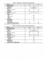
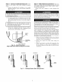
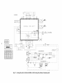
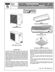
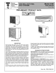
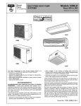
GENERAL
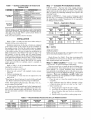
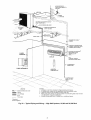
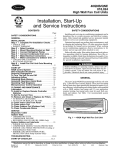
The heat pump hi_l walt tan coil units (Fig. 1) come with
supplemental electric heat. If your application requires heating,
heat pump units must be used, both outdoors and indoors. See
Table 1 for recommended system combinations.
)
Fig. 1 -- Typical High Wall Fan Coil Unit
Manufacturer reserves the right to discontinue,
PC 111
or change at any time, specifications
Catalog No. 534-043
Printed in U.S.A.
or designs without notice and without incurring obligations.
Form 40QN-6SI
Pg 1
9-02
Replaces:
40QN-4SI
Table 1 -- System Combinations for Indoor and
Outdoor Units
SYSTEM
Cooling Only
Systems
Heat Pump
Systems
INDOOR
UNIT
OUTDOOR
40QNB018
38HDC, HDL018
40QNB024
38HDL018,
40QNB018 (2)
619ENX0180E0
38HDS024*
538ANX, JNX018
619ENX0240E0
538JNX018,
(2) 619ENX0180E0
40QNH018
538SNX024
38BK018
40QNH024
619ENX0180H0
38BK024
538DNX018
619ENX0240H0
538DNX024
*Multi-split systems can accommodate fan coil
with one condensing unit. The combinations
those which use only high-wall units (not in
other type of fan coil unit). Refer to system
Price Pages for more details.
UNIT
38HDC,HDL024
538ANX,JNX024
Step 1 -- Complete
COOLING
MODE
Maximum
units of various types
listed in this table are
combination with any
presale literature or
Minimum
Indoor
Unit
Outdoor
Unit
Indoor
Unit
Outdoor
Unit
95 F DB
71 FWB
115FDB
67 F DB
57FWB
55 F DB*
0°FDB1-
HEATING MODE
Maximum
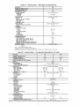
INSTALLATION
Refer to Table 1 to make sure the correct indoor unit(s) is
installed with the correct outdoor unit.
Installation instructions for the tan coil units are contained
in this manual. Reth to this manual for proper installation of
the complete system. Note that the outdoor units are shipped
with installation and service instructions for basic installation
of the outdoor section. Be sure to make the modifications in
Make Connections to the Outdoor Unit section on page 13 of
this literature, so that the outdoor unit will operate properly
with the control system. Be sure the unit will be operated within the application guidelines shown in Table 2. When installing
the outdoor unit, note that for cooling operation below 55 F, it
is necessary to equip the outdoor unit with the low ambient
control accessory. The low ambient control is standard on
ruuhi-split units.
Refer to Table 3 for all recolrnnended accessories when
installing low ambient control.
To install this system, you will need:
• Indoor t;an coil sections* with standard wireless remote
controller
• Outdoor condensing unit
• A low-ambient or winter start kit (if required t\_r your
application)
*More than one tan coil unit may be used with the muhi-split
unit. Refer to ruuhi-sptit system Price Pages for full details.
NOTE: Field-supplied refrigerant pipe, drain pipe, wire, etc.,
are also required to install unit.
Be sure you have the required parts betbre beginning installation. The indoor section uses a microprocessor control system to deliver optimum comfort and efficiency. Be sure to follow these instructions carefully to obtain proper functioning of
the unit.
Table 3 -- Recommended
LOW AMBIENT
CONTROL
Checks
Table 2 -- Application Ranges
NOTE: Only match systems as shown in this table.
UNIT
Pre-lnstallation
UNPACK UNIT
Store the unit in the original packa_ng
until it is moved to the final site for installation. When removing the unit tiom the carton, lift by its 4 comers. Also, note that
there is a plastic bag containing mounting scaews taped to the
ruounting bracket.
INSPECT SHIPMENT
tYpon receipt of shipment check
the unit (Fig. 1) for dmnage. Forward claim papers directly to
the transportation company. Manuthcturer is not responsible
for damage incurred in transit.
Minimum
Indoor
Unit
Outdoor
Unit
Indoor
Unit
Outdoor
Unit
80 F DB
71 F WB
75 F DB
65 F WB
55 F DB
0° F DB
LEGEND
DB -WB --
Dry Bulb
Wet Bulb
*Single zone systems.
1-Multi-zone systems.
NOTE: Unit may be equipped with a low-ambient
start kit that will allow operation down to -20 F.
control or winter
Check all items. See Table 4. If any item is missing notii_
your distributor. To prevent loss or damage, leave all parts in
their original packages until installation.
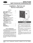
Step 2 -- Select Location -- Consult local building
codes and NEC for special installation requirements.
There are several ways to install the unit for different types
of wall construction. These instructions do not cover all installation methods. As a typical installation, these instructions
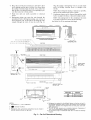
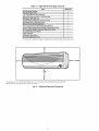
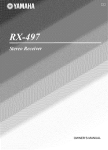
focus primarily on mounting the unit to wall studs in new construction. See Fig. 2 for unit dimensions and Fig. 3 for required
clearances. Plan your installation carefully before you
begin. Listed below are some guidelines to follow when deterruining a location for the unit.
1. Place the unit so it faces the nonnat location of room
occupants.
2. Allow sufficient space for airflow clearance, wiring,
reliigerant piping, and unit servicing. See Fig. 2 and 3.
3. Select walls that are:
a. Strong enough to support the unit's weight.
b. Accessible to convenient condensate drainage.
c. Free of obstacles that may block air circulation to
the fan coils.
d. Outside walls (if possible) to make piping easier.
Accessories for Low Ambient Control
CRANKCASE
HEATER
WINTER
START KIT
ISOLATION
RELAY
WIND BAFFLE
38BK, 538BNX
53DS-900---60
--
KAAWS0101AAA
KHAIR0101AAA
53DS-900---070
38HDC, 538ANX
53DS-900---60
KAACH 1201AAA*
KAAWS0101AAA
--
53DS-900---070
38HDL, 538JNX
53DS-900---60
--
KAAWS0101AAA
--
53DS-900---070
*Not required for 38HDC018.
4. Place the top of the fan coil unit up to 10 ft above floor
level, making sure the unit is at least 10 in. down from
the ceiling to permit proper air intake. Also, make sure
that the unit is not placed directly over anything to prevent filter removal or block airflow.
Once the piping is through the wall, it can run inside
walls, in ceilings, between floors, or straight to the
outside.
NOTE: Run refrigerant piping as directly as possible,
and avoid any unnecessary turns or bends.
7. Condensate piping can be directed through the inside
wall to an approved drain, or directed straight outside.
NOTE: The piping hole for the condensate line must
be sloped downward to ensure proper drainage.
See Tables 5A-5F for maximum line length.
5. Make sure units are easily accessible to electrical
power.
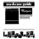
6. Refrigerant piping can enter the unit through the
prepunched holes. Refrigerant piping cml run up or
do,a_ along the wall, to the right or left along the watt,
straight through the wall, or into the wall (Fig. 4).
FOR
REFR]GERANT,
POWER,
AND
DRAIN,
SIGNAL
tINES
FRIGHT SIDE
VIEW]
14.17
[360]
•
J
_NOCKOUT FOR RIGHT
x_
_
A_'
I
...............
1
/
[105]
--
UNIT
2.
I_
in (
POWER•
LINES
I
[220]
POWER,
OUTLI_
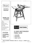
UNIT SIZE
WEIGHT
018
39 Ib (17.5 kg)
024
43 Ib (19.5 kg)
[4701
[4SOl
NOTES:
1. Dimensions
DRAIN,
LINEB
REFRIGERANT*
SIGNAL
l
L INFRAREO REMOTE OVERRIDE SWITCH
(BEHIND ACCESS COVER}
REFRIGERANT,
AND
EIGNAL
AND
J
/
DE
ORAIN,
_2
+35 DIA
[B01
) are in millimeters.
Direction of airflow.
3. Refrigerant, drain, and power connections
unit rear, bottom, left side, or right side.
may be made in
(NOTE Z12B3
3 )
4. Refrigerant is metered by AccuRater® device in the fan coil unit. A
thermostatic expansion valve is used in the outdoor unit on multi-split
applications. Insulate both refrigerant lines on heat pump and multisplit applications.
5. The 4-in. left side clearance is an absolute minimum. Clearances of
10qn. are recommended for proper unit operation.
6. Do not insert a trap in condensate drain line. The drain is internally
trapped.
Fig. 2 -- Fan Coil Dimensional Drawing
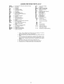
Table4 --
High Wall Unit Package Contents
ITEM
QUANTITY
Unit Mounting Template
1
Unit Mounting Bracket
1
1-in. Lag Screws For Unit Mounting
8
Hollow Wall Anchor Bolts For Unit Mounting
5
Wall Sleeve With Wall Cap
1
Infrared Wireless Remote Control Assembly
1
AAA Batteries (For Remote Control)
2
Remote Control Mounting Bracket
1
3/8-in. Lag Screws For Remote Mounting Bracket
2
35 ft Long High Voltage Power Wiring (2-wire with ground)
1
35 ft Long Low Voltage Thermistor
1
Wiring (1613 wire)
AccuRater@ Body and Piston*
Owner's Manual
1
1
Installation
1
Instructions
Warranty Registration
Card
*For heat pumps: additional
1
heating AccuRater body and piston shipped with outdoor unit.
t
10"*
I
m12"
/
+
36 _
!
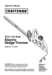
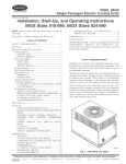
*A clearance of 4 in. is the absolute minimum. A 10-in. clearance is recommended
NOTE: Remove unit front cover for control box access.
for proper operation.
Fig. 3 -- Minimum Required Clearances
,,,,,,,,,,,,,,,,,,,-D
POSSIBLE
4. Temporarily hang the unit on the bracket to check
location and level.
PIPING DIRECTIONS
SIDE
KNOCKOUT
RIGHT
__
_"__
A
..............
BOttOM
KNOCKOUT
LEFT
SiDE
_
II
It
_
KNOCKOUT
U
PREPUNCHED
HOLES
\
FOR LEFT
SIDE PIPING
FOR RIGHT
SIDE PiPiNG
FOR
BOTTOM/REAR
PIPING
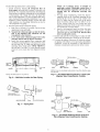
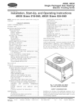
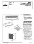
Fig. 4-
Refrigerant Piping
Step 3 -- Attach Mounting Bracket to Wall
1. Decide how the refrigerant wilt be piped. It'necessary,
knock out the appropriate pre-punched holes (Fig. 4)
on the unit for piping and electrical connections.
2. Remove the bracket from the fan coil unit.
3. Using a carpenter's level, fasten the mounting brackets
into the studs in the wall at least 10 in. away from the
ceiling with the 8 screws provided. Always be sure to
insert screws into the top 2 holes indicated in Fig. 5.
Make sure the attached bracket will support a 200 lb
vertical load. For a masonry wall, anchor shields can
be used to attach the bracket to the wall.
If mounting bracket is not mourned level, the indoor section
will be mounted unevenly, and condensate drainage water
may drip onto the floor. Also, a gap between the bracket and
the wall may result in vibration mid noise from the iMoor
section.
Mark and cut condensate and piping holes.
a. For piping through the wall, mark the wall below
the condensate connection and cut a 2t/2-in. hole
into the wall at either point "A" or point "B" in
Fig. 6.
NOTE: The 21/2-in. hole must be made at a do,amward
slope to ensure proper condensate drainage. See Fig. 7.
Slope the condensate line at a minimum pitch of 1/4-in.
per foot of line. The condensate line cannot be mn up
for upper piping connections
only refrigerant lines
may be mn up.
b. Push the wall sleeve (factory supplied with the
unit) through the 21/2-in. wall opening.
Step 4 -- Connect Refrigerant Piping -- Fan coil
units may be connected to the outdoor units using field-supplied
refrigerant grade piping. Refer to Tables 5A-5F for the correct
size piping. The length of reffigermlt pipe depends on the unit
placement and building structure; mn pipes as directly as possible. For piping requirelnents over 50 ft of total ran, or more
than 25 ft of lift, consult the long line application guidelines, or
contact your local representative. For multi-split systems, the
maximum pipe length is 50 ft.
DO NOT BURY MORE THAN 36 IN. OF REFRIGERANT PIPE IN THE GROUND. If any section of pipe is
buried, there must be a 6-in. vertical rise to the valve connections on the outdoor unit. If more than the recolrnnended
length is buried, refiigerant may mi_ate to the cooler, buried section during extended periods of unit shutdown, causing reffigermlt slugging and possible colnpressor dmnage at
start-up.
/
TOP HOLES
q
I
t
FAN COIL
UNiT BOTTOM
TOP VIEW
BACK VIEW
Fig. 5 -- Bracket Mounting
Use the following instructions to connect piping.
1. Install insulation. Insulate all refrigerant
lines on
heat pumps and multi-split systems to prevent condensation. It is extremely important that all refrigerant
lines and the AccuRater,¢<)metering device be insulated
on heat pumps. On cooling only units, the liquid line
may be left uninsulated. Use any acceptable heat resistant, closed-celt foam insulation (minimum 3/s-in. wall
thickaless). When insulating piping, cap the ends and
slide insulation over the piping. Insulation can also be
cut and placed over piping.
2. Run the liquid and gas refrigerant piping.
a. Run pipes as directly as possible, and avoid any
unnecessary turns and bends.
b. Suspend the refrigerant pipes so that the insulation is not damaged
and vibrations
are not
transmitted to the structure.
c. Leave slack in the refrigerant pipe between the
structure and the unit to absorb vibrations.
d. Install the factory-supplied flare connection and
AccuRater metering device in the liquid line at the
fan coil unit (Fig. 8). Make sure the arrow on the
metering device body points AWAY FROM the
fan coil unit. Use Table 7 to verily that the correct
piston for your system has been shipped with the
unit.
FAN COIL
_
UNIT
-..........._l_'_",,._____.J
_r..-..._.L...--_
_
) _/'_
NOTE: No AccuRater
device is installed on
multi-split systems. Multi-split systems have a
TXV (thermostatic expansion valve) in the condensing unit for refrigerant
metering
and
control.
e. On heat pump installations, install the factorysupplied piston in the AccuRater metering device
located in the service valve on the outdoor unit
(Fig. 9). Make sure the Teflon seal on the piston
faces toward the outdoor unit. Use Table 7 to verify the correct piston for your system has been
shipped with the unit. Refer to the outdoor installation instructions for more details.
f. Install a field-supplied liquid line filter drier near
the outdoor unit. On heat pump systems, a bi-flow
filter drier must be used. DO NOT install a filter
drier in multi-split systems.
3. Insulate and caulk the wall openings to reduce air infiltration and refrigerant pipe vibrations on the structure.
4. Evacuate the piping, if necessary. If either the refrigerant piping or the indoor coil is exposed to atmospheric
conditions, it must be evacuated to 1000 microns to
eliminate contamination and moisture in the system.
ON
_]
BODY
(WITH ORIFICE)
NOTE: Arrow on AccuRater
from the coil.
NOTE: Use either point "A" or point "B."
Fig. 6 -- Wall Hole Location
•
°
°
_
for Rear Piping
,"
SEAL_
SCREEN
CAP
body points in free flow direction
away
Fig. 8 -- AccuRater Metering Device in Liquid Line
(Bypass Type Components); Cooling
,
_ _I-LOWER
WALLSLEEVE
--
/
(FACTORY SUPPLIED)
_//SvAERv_
(INDOOR SIDE) [
"
WALL
.
I (OUfDOOR
VECE
TEFLON
SEAL
SIDE)
Fig. 7 -- Piping Hole
L====J
(W _'T'H_
'_)RI
FICE)
SCREEN
CAP
Fig.9 -- AccuRater Metering Device at Service
Valve (Bypass Type Components); Heating
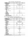
Table 5A -- Physical Data -- 38HDC, 538A Condensing
Units
UNIT SIZE
NOMINAL
OPERATING
CAPACITY
11/2
018
150
(Tons)
WEIGHT
(Ib)
REFRIGERANT
TYPE
Control (Cooling)
Charge (Ib)
OUTDOOR
FAN
Rpm
Diameter (in,),,.No.
of Blades
Pitch (Degrees)
Motor Hp
Nominal Air Cfm
OUTDOOR
COIL
Face Area (sq ft).,.No,
Finstin.
AccuRater_
18_.3
25
1/8
850
1720
of 40 va is provided
Direct
Drive
18...3
27
1/8
850
1720
I
Copper
CONTROLS
High-Pressure
(psig)
Cut-in
Cutout
Low-Pressure
(psig)
Cut-in
Cutout
Fusible Plug
Control Voltage*
REFRIGERANT
LINES
Connection
Type
Liquid Line OD (in.)
Vapor Line OD (in.)
Maximum Length (ft)
Maximum Lift Fan Coil (Above
Maximum Lift Fan Coil (Below
*24 v and a minimum
R-22
Piston at Fan Coil Unit
See Table 6
Propeller,
of Rows
2
024
154
I
6.1 ,_1.5
15
Tube, Aluminum
I
I
Fin
6.1 ...2
15
320 +_20
426 _+ 7
22 _+5
7_+3
210 F
24
Sweat
Outdoor)
Outdoor)
(ft)
(ft)
s/8
200
65
3/8
150
5/8
200
65
3/8
150
I
in the fan coil unit.
Table 5B -- Physical Data -- 38HDL, 538JNX Condensing
Units
UNIT SIZE
NOMINAL
CAPACITY
UNIT OPERATING
(Btuh)
WEIGHT
(Ib)
REFRIGERANT
TYPE
Control
Charge (Ib)
OUTDOOR
FAN
Rpm
Diameter (in,),,,No.
of Blades
Fan Pitch (Deg)
Motor Hp
Nominal Airflow (cfm)
OUTDOOR
COIL
Face Area (sq ft)..,No, of Rows
Fins per inch
CONTROL
PRESSURESTAT
Low Pressure
Cut-out (psig)
Cut-in. (psig)
Fusible Plug
REFRIGERANT
LINES
Connection
Type
Maximum Length (ft)
Maximum Lift (ft) -- Fan Coil (Above Outdoor)
Maximum Lift (ft) -- Fan Coil (Below Outdoor)
18,000
018
130
AccuRater_
Propeller
18_.3
25
1/8
850
1720
Copper
6.1 ...1
20
24,000
024
136
I
R-22
Piston at Fan Coil Unit
See Table 6
Type, Direct
Drive, Horizontal
I
Tube, Aluminum
I
I
Settings
7_+3
22 _+5
210 F
Sweat
100
65
75
18...3
27
1/8
850
1720
Plate Fin
6.1 ,..1.5
20
Table 5C -- Physical Data -- Multi-Split Condensing Units
UNIT
SIZE
NOMINAL
O24
CAPACITY
OPERATING
2
(Tons)
WEIGHT
159
(Ib)
REFRIGERANT
TYPE
Control (Cooling)
Charge (Ib)*
Circuit A
Circuit B
OUTDOOR
FAN
Rpm
Diameter (in,),..No.
Pitch (Degrees)
Motor Hp
Nominal Air Cfm
R-22
TXV in Condensing
See Table 6
Propeller,
of Blades
Direct
850
18...3
27
Drive
l&
1720
OUTDOOR
COIL
Face Area (sq ft),..No,
Fins/in.
Copper
of Rows
CONTROLS
High-Pressure
(psig)
Cut-in
Cutout
Low-Pressure
(psig)
Cut-in
Cutout
Fusible
Plug
Control
Voltage
REFRIGERANT
LINES
Connection
Type
Vapor Supply Line Quantity...OD
(in,)
Vapor Return Line Quantity,,.OD
(in.)
Maximum
Length (ft)
Maximum
Lift Fan Coil (Above Outdoor)
Maximum
Lift Fan Coil (Below Outdoor)
EXTERNAL
Unit
Tube, Aluminum
6.1 ...2
15
Fin
320 _+20
426 _+ 7
22_+5
7+_3
210 F
24
Sweat
2...3/8
2...5/8
5O
301301-
(ft)
(ft)
FINISH
Alpine
Mist (Beige)
LEGEND
TXVThermostatic
Expansion Valve
*Charge is based on 25 ft of interconnecting
line.
1-Maximum system lift is 30 ft between lowest system
component
and highest
system
component.
Table 5D -- Physical Data -- Cooling Only High Wall Fan Coil Units
UNIT SIZE
018
NOMINAL
CAPACITY
NOMINAL
SIZE (Btuh)
OPERATING
MOISTURE
WEIGHT
REMOVAL
024
11/2
(Tons)
(ib)
2
18,000
24,000
38.5
42.9
5.6
RATE (Pints/Hr)
6.3
FINISH
White
REFRIGERANT
Control (Cooling)
System Charge Required
INDOOR FAN
Bpm,..Cfm
High
Rpm,.,Cfm
Medium
Bpm,,.Cfm
Low
Motor Watts
Blowers -- No..,,Size
R-22
Metering Device
4.6
I
5.3
Direct Drive Centrifugal
1120.,,550
1470,.,570
1050, ..500
1370, ..466
950...450
1270...417
44
49
2...3.94 x 17.8
2...3.94 x 17.8
AccuRater®
(Ib)*
(in.)
INDOOR COIL
Face Area (sq ft)
No. of Rows
Finstin,
Circuits
FILTERS
(Quantity)
AIRSWEEP
Horizontal
Vertical
Copper
Fin
2.56
3
18.1
3
Cleanable
(3) 111/2 x 173/4
Size (in,)
Manual
Automatic
CONTROLS
Remote Controller
Freeze Protection
Auto. Restart
Diagnostics
Timer Mode
Test Mode
Dehumidification
Mode
Fan Mode
Control Voltage
Integrated Microprocessor
Wireless
Yes
Yes
Yes
24-Hour Startup/Shutdown Type
Yes
Yes
High/Medium/Low/Auto.
24 v
REFRIGERANT
LINES
Connection
Type
Liquid Line OD (in.)
Vapor Line OD (in.)
CONDENSATE
Tube, Aluminum
2.56
2
15.9
2
DRAIN
Male Flare
s/8
5/8
CONNECTION
(in.)
I
3/8
s/8
5/80D, 7/16ID
*Full factory charge shipped in outdoor unit. Charge shown is for smallest system combination and is determined based on 25 ft of line.
Table 5E -- Physical Data -- Outdoor Heat Pump Units
UNIT
SIZE
NOMINAL
018
CAPACITY
OPERATING
WEIGHT
REFRIGERANT
TYPE
Control (Cooling)
Control (Heating)
Charge (Ib)*
(Tons)
(Ib)
024
11/2
2
154
167
R-22
Piston at Fan Coil Unit
Piston at Outdoor Unit
See Table 6
AccuRater®
AccuRater
CRANKCASE
HEATER (Watts)
OUTDOOR
FAN
Rpm
Diameter (in,),..No.
of Blades
Pitch (Degrees)
Motor Hp
Nominal Air Cfm
OUTDOOR
COIL
Face Area (sq ft),..No,
Fins/in.
19
I
Direct
Propeller,
19
Drive
850
18_.3
25
l&
1720
850
18_.3
27
1/s
1720
Copper
of Coils
Tube, Aluminum
I
I
6.1 ...1.5
15
CONTROLS
High-Pressure
(psig)
Cutout
Cut-in
Liquid Line Low-Pressure
(psig)
Cutout
Cut-in
Fusible Plug
Defrost Method
Accumulator
Control VoltagelREFRIGERANT
LINES
Connection
Type
Liquid Line OD (in,)
Vapor Line OD (in.)
Maximum
Length (ft)
Maximum
Lift (Fan Coil Above) (ft)
Maximum
Lift (Fan Coil Below) (ft)
Fin
6.1 ...2
15
320 _+20
426 _+ 7
7_+3
22_+5
210 F
Time and Temperature
Yes
24 v
Sweat--Suction;
Defrost
Flare--Liquid
3/8
s/8
200
65
150
s/s
5/s
200
65
150
*These units are shipped with a holding charge only,
1-A 24-v transformer
is provided in the fan coil unit; size 018 and 024 units have their own transformers.
Table 5F -- Physical Data -- Heat Pump High Wall Fan Coil Units
UNIT
SIZE
018
NOMINAL
CAPACITY
NOMINAL
SIZE (Btuh)
OPERATING
WEIGHT
MOISTURE
FINISH
6.3
White
R-22
AccuRater®
Piston in Fan Coil
AccuRater
Piston in Outdoor Unit
See Table 6
Direct
1250/530
1150/490
1050/430
42.3
2...3.94 x 17.8
(in.)
Copper
Drive Centrifugal
1470/570
1400/466
1300/447
49
2...3.94 x 17.8
Tube, Aluminum
Fin
2.56
2
15.9
2
2.56
3
18.1
3
Cleanable
2,.,111/2 x 173/4
(in,)
Manual
Automatic
CONTROLS
Remote Controller
Options
Diagnostics
Defrost Method
Timer Mode
Warm Start Feature
Test Mode
Freeze Protection
Dehumidification
Auto. Changeover
Fan Mode
Auto Restart
Control Voltage
REFRIGERANT
LINES
Connection
Type
Liquid Line OD (in,)
Vapor Line OD (in.)
CONDENSATE
24,000
42.9
5.6
RATE (Pints/Hr)
REFRIGERANT
Control (Cooling)
Control (Heating)
Charge Required (Ib)
INDOOR FAN
Rpm/Cfm
High
Rpm/Cfm
Medium
Rpm/Cfm
Low
Motor Watts
Blowers Quantity..,Size
INDOOR COIL
Face Area (sq ft)
No. of Rows
Fins/in.
Circuits
FILTERS
Quantity,..Size
AIBSWEEP
Horizontal
Vertical
2
18,000
38.5
(Ib)
REMOVAL
024
11/2
(Tons)
DRAIN
CONNECTION
Integrated Microprocessor
Wireless
Yes
Demand Defrost
Yes
Yes
Yes
Yes
Yes
Yes
High/Medium/Low/Auto.
Yes
24 v (provided)
(in,)
Flare
3/8
s/8
5/80D, 7/16ID
*Outdoor unit is shipped with a holding charge. The amount of the charge is determined based on 25 ft of line.
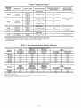
Table 6 -- Refrigerant Charge
SYSTEM
HIGH
WALL
(Btuh)
I
INDOOR UNIT
OUTDOOR
UNIT
ADDED CHARGE*
FACTORY CHARGE
Coolin_
18,000
(over 50 ft tubing)
3.6
Operating
38HDL018
538JNX
40QNB024
619ENX024
(Ib)* I
Only
38HDC018
538ANX
40QNB018
619ENX018
Charge
3.8
38HDLO18
538JNX
24,000
(25-50 ftCHARGE
tubing)
I OPERATING
Operating
38HDC024
538ANX
5.3
38HDLO24
538JNX
Operating
.58 Oz. For each foot
over 50'
3.8
Charge
6.014.4
Charge
Heat Pumps
18,000
40QNH018
619ENX018
38BK018-3
538DNX
2.0 Holding Charge
4.951-
24,000
40QNH024
619ENX024
38BK024-3
538DNX
2.0 Holding Charge
5.10t
.58 Oz. For each foot
over 50'
Multi-Split
*Charge amount determined based on 25 ft of line. Check charge for longer lines using superheat method. See outdoor unit installation, start-up, and service instructions for system charging procedures. No additional charge is needed from 25 to 50 ft of line length.
1-Total system charge.
Table 7 -- Piston Requirements for Elevation Differences
INDOOR COIL BELOW OUTDOOR
Elevation
Difference
38HDC*
538ANX
Indoor Piston
Size 018/024
38HDL018*
538JNX018
Indoor Piston
Size 018/024
Standard
26- 50'
49/57
45/53
49/53
45/49
51- 75'
43/52
76-100'
101-125'
42/49
40/47
126-150'
39/47
N/A
INDOOR
UNIT
38HDL024*
538JNX024
Indoor Piston
Size 024
38BK
538DNX
Indoor Piston
Size 018/024
Outdoor Piston
Size 018/024
57
53
51/59
47/55
47/52
47/52
43/47
52
45/53
51/57
N/A
N/A
N/A
N/A
43/52
42/49
53/59
55/61
41/49
57/62
N/A
COIL ABOVE OUTDOOR
Elevation
Difference
38HDC*
538ANX
Indoor Piston
Size 018/024
38HDL018*
538JNX018
Indoor Piston
Size 018/024
Standard
49/57
49/53
26-50'
53/61
53/57
UNIT
38HDL024*
538JNX024
Indoor Piston
Size 024
Indoor Piston
Size 018/024
Outdoor Piston
Size 018/024
57
51/59
47/52
61
55/63
47/52
*No piston in outdoor unit.
NOTE: The multi-split systems do not use the AccuRater'_" device. They have a TXV in the
condensing unit for refrigerant metering and control.
10
38BK
538DNX
Step 5 -- Connect Condensate Drain Line -- Observe all local sanitary codes when installing condensate
drains.
Step 6 -- Make Electrical Connections -- Be sure
field wiring complies with local building codes and NEC, and
unit voltage is within limits shown in Table 8. Refer to Table 9
for units with electric heat.
1. Connect the drain line by inserting a 5/8-in. (inside
diameter) rigid PVC pipe over the drain connection.
Refer to Fig. 10.
Contact local power company to correct hnproper line
vohage.
The drain tube extension must be securely Ihstened to the
condensate drain. Failure to do so can result in condensate
water dripping onto the floor.
To avoid personal injury or damage to unit, do not make
electrical connections until all power sources are shut
do,a_, locked out, and tagged off Failure to do so could
resuh in personal injury or unit damage.
2. To ensure re mllar flow of condensate water, the drain
pipe should be pitched toward an open drain or sump
at a downward slope of at least l/4-in, per foot. Refer to
Fig. 11.
I
Operation of unit on hnproper line voltage constitutes abuse
and could affect warranty. Refer to Table 8 for permissible
operating limits. Do not install unit in system where voltage
may fluctuate above or below permissible limits.
which might form a trap. Do not insert a trap in the drain
IMPORTANT:
sure the
drain piping has no slack
line;
the drain is Be
internally
trapped.
3. Insulate the condensate drain lines that are located in
or above an occupied area with a condensate proof
material such as polyurethane or neoprene.
NOTE: Use type NM power cable only (per NEC; provided for
fro1coil units only) between disconnect switch mid unit.
NOTE: Install the branch circuit disconnect (field supplied) per
NEC of adequate size to handle the unit's starting cunent.
Locate the disconnect within sight liom and readily accessible
fioln the unit, per Section 440-14 of NEC. Some codes allow
the indoor unit to share a disconnect with the outdoor unit if the
disconnect can be bcked; check local code before installing in
this manner. To make electrical connections:
INDOOR
UNIT
PIPING
1. Remove the screws holding the front cover of the ihn
coil unit, and remove the front cover. Save the screws
and screw covers l\_r reinstatlation.
2. Remove the control box strain relief clamp (see
Fig. 12).
3. Remove any factory test leads still connected to the
power tenninat box. These leads (if applicable) are
for factory testing only and cannot be used for power
connections.
DRAIN CONNECTION
Fig. 10 -- Drain Connection
(Right Side Shown When Facing Fan Coil Unit)
INCORRECT
INCORRECT
INCORRECT
CORRECT
_WALL
6
6
UNIT
'_-----
m
"/777
Fig. 11 -- Drainage System (Rear Piping Shown)
11
DRAIN
PIPING
Do not short circuit the indoor unit's transformer
it is
l'used. The transformer can be short circuited by connecting
the wrong wires or by touching a live wire to the side of a
grounded control box.
TBI
-
SCREW
208/230 VOLT
FSINGLE-PHASE CONN.J
INDOOR
oTOooNNECT
L
RELIEF
SFRAIN
CLAMP
_
LABEL CAUTION
t
NOTE: This shows item locations only. Front cover of fan coil unit
must be removed to access terminal boards.
Fig. 12 -- Fan Coil Unit Wiring Preparation
EQUIP
FAN COIL
GND
UNITS
LEGEND
4. Route the factory-supplied ground and power wires
from terminal block 1 (TB1) to the field-supplied
disconnect switch.
CONN
-EQUIP GND -TB
--
Connection
Equipment Ground
Terminal Block
Fig. 13 -- Line Power Connections
According to NEC and most local codes, the unit must have
an uninterrupted, unbroken mou_d to minimize personal
injury if an electrical thult should occur. The _ound may
consist of electrical wire or metal conduit when installed in
accordance with existing electrical codes. Failure to follow
this warning could result in an electric shock, tire, or death.
TERMINAL
BLOCK
fiB+)
Route the factory-supplied line power leads (see
Fig. 14) from the field-supplied, indoor unit disconnect
to the tan coil unit TB1 (see Fig. 13 and 14). Run the
wire through the strain relief on the control box (see
Fig. 12). When routing wire in the fan coil unit, keep
the wire away tiom refrigerant and condensate piping
and any sharp edges on the unit.
CONNECTION
CORD
Fig. 14-
High Voltage Connections
Table 8 -- Electrical Data
INDOOR
UNIT
OPERATING
V (Single-Ph,
60 Hz)
Cooling
Only
018
024
Heat
Pump
018
024
2081230
VOLTAGE*
FAN
Max
Min
LRA
FLA
253
187
3.2
0.53
LEGEND
FLA
HACR
LRA
MCA
NEC
------
WATTS
MCA
MAX FUSE
OR HACR TYPE
CKT BKR AMPS
94
10.9
15
*Permissible limits of the voltage
satisfactorily.
Full Load Amps
Heating, Air Conditioning, and Refrigeration
Locked Rotor Amps
Minimum Circuit Amps per NEC Section 430-24
National Electrical Code
range at which
unit will operate
Table 9 -- Electric Heater Data
INDOOR UNIT
VOLTS-Ph
(60 Hz)
INPUT
AMPS
MIN
WIRE
SIZE
230-1
7.8
1.8
14
024
230-1
7.8
1.8
14
LEGEND
AWG --
kW AT 230 V
018
American Wire Gage
12
(AWG)
START-UP
Step 7 i
Make Connections
to the Outdoor
Unit
COOLING ONLY SYSTEMS
To connect the outdoor unit
to the tan coil unit so the system will operate correctly:
Route 2 field-supplied wires of 18-gage AWG (American
Wire Gage) therlnostat cable between the low voltage terlninal
block of the tan coil TB-2 and the outdoor unit's low voltage
terlninat block. Connect the wires between terlninals C and xA
Complete the following checks and the Start-Up Checklist
on page CL-1 before system start-up. Refer to the outdoor unit
installation, start-up and service instructions for system start-up
procedures and retiigerant charNng methods.
1. Check the condensate drainage system.
Add water to check the drainage flow. If the water
does not flow regularly, check the pipe slope or see if
there are any pipe restrictions.
2. Make sure that all wiring connections are correct and
tight.
3. Make sure that all barriers, covers, and panels are in
place.
4. Ensure that the filters have been installed and that the
discharge louvers are correctly positioned.
HEAT PUMP SYSTEMS
To connect the heat pump unit
to the tZancoil unit so the system will operate correctly:
Route 5 field-supplied wires of 18-gage AWG (American
Wire Gage) therlnostat cable between the low voltage terminal
block of the tan coil TB-2 and the outdoor unit's low voltage
terlninal block. Connect the wires between terlninals R, C, Y,
G, andO.
Route the factory-supplied thermistor cord fiom the low
voltage terminal board in the control box of the fan coil unit
TB-3 to the outdoor unit's low voltage terminal block. Route
the wire carefully so that it will not be damaged.
Never operate unit without a filter. Damage to the unit or
personal injury may result.
I
IMPORTANT: DO NOT RUN THE THERMISTOR
CABLE 1N THE SAME CONDUIT AS THE POWER
WIRING.
Step 8 i
Bracket
Install Fan Coil Unit Onto
5. If the unit is equipped with a crankcase heater, energize it a minilnum of 24 hours before starting the unit.
To energize the crankcase heater only set the unit in off
mode and close the outdoor unit disconnect.
6. Fully backseat (open) the liquid and vapor tube sewice
valve s.
Mounting
7. The unit is shipped with valve stems frontseated and
caps factory installed. Replace the stem caps after system is opened to refrigerant flow (backseated).
Replace the caps finger tight.
8. With the remote controller, turn on the unit and operate
it in each mode (as applicable) for 15 minutes to test
for proper operation. Do not operate in cooling mode if
the outdoor temperature is below 55 F or 0 ° F (multisplit) unless the unit is equipped with a low ambient
control or winter start kit (multi-split). Do not operate
in heating mode (heat pump systems only) if the outdoor temperature is above 75 F.
9. Test for proper refrigerant charge using the superheat
method or subcooling method t\_r multi-split.
10. Explain basic system operation to the o,amer.
1. Hook the fan coil unit onto the top of the mounting
bracket. See Fig. 15.
2. Snap the fan coil unit onto the mounting bracket as
shown in Fig. 15.
I
heard as the hook on the unit is secured into the hole on
IMPORTANT:
An audible
snapping
soundmounted.
will be
the mounting bracket.
Be sure unit
is correctly
TOP
• ,A-
"R
o_
,j'_
•
fl
Ii
• ._,|
r--Z
"
1
HOOK
LOCATIONS
LlO
--101/4"
MOUNTING
BRACKET
HOOK
HOLE
e*.
_11
Fig. 15 -- Mounting Unit to Bracket
13
1/4".---._
ControlSystem --The
indoor unit is equipped with a
microprocessor control which operates the system. This control
is located in the control box of the fan coil unit, with thermistors located in the thn coil inlet and on the indoor coil. The
heat pump fan coil units also have thermistors on the outdoor
coil and in the outdoor air inlet. These thermistors monitor system operation and control the operating mode. To change settings or operation modes, use the fiactory-supplied inliared
wireless remote controller. This controller allows the fan coil
unit to operate fiom within the same room without any wire
connections to the unit.
WIRELESS REMOTE CONTROLLERS
A wireless remote controller is supplied for system operation of all hi_l wall
units. Each battery-operated wireless (inliared) remote controller may be used to control more than one unit. The wireless
relnote controller has a maximum range of 20 feet. The fan coil
unit is equipped with an emeNency switch which allows operation if the remote contxoller malfunctions or is misplaced.
Because the controller uses inliared communication, all of the
following must be true for the controller to work properly:
20'
BRACKET
Fig. 16 -- Mounting
1. The power to the tan coil unit must be on.
2. The batteries in the controller must be good.
3. The controller must be within range of and pointed
directly at the thn coil unit.
4. The tan coil unit's 3-position switch must be set in the
remote position.
The remote controller includes a wall-mounted bracket. To
install the bracket, attach it to the wall as shown in Fig. 16
using double-sided tape included in the remote controller
assembly. Install the thctory-supplied batteries into the remote
controller per To hlstatl or Replace Remote Controller Batteries section on page 17, and place the controller into the bracket
so that it is ready to use.
Remote Controller
Bracket
FLAP_
2:00
Ae®
ON/OFF
®@
SET BACK
After Extended Shutdowns -- If the system has been
turned off tbr more than 12 hours, turn on the indoor and
outdoor unit disconnect switches to supply power to the system
for 12 hours BEFORE starting the system.
Seasonal Changeovers--When
changing the heat
pump system ftom cooling to heating or heating to cooling, or
before starting cooling only system after it has been out of use
for the winter season, perform the following steps BEFORE
starting the system:
1. Inspect and clean the outdoor unit, particularly the
coil.
Fig. 17 -- Remote Controller
2. Clean or replace the air filters in the indoor unit.
3. Clean the indoor unit drain pan and drain pipe, and
remove any obstructions.
4. Turn on the indoor and outdoor unit disconnect
switches to supply power to the system 12 hours
before starting the system.
CLOSE
._'
START
CLOSe/
COOL*
/
START
COOLING - DIRECT
LOUVERS SO AIR
HEAT*
HEATING
- DIRECT
LOUVERS SO AIR
BLOWS DOWN
VERTICAL
_ISCNARGE)
OUT
HORIZONTAL
DISCHARGE)
ToTurn the Unit On and Off-- To turn the unit on,
press the ON/OFF button (see Fig. 17). The unit will start. To
stop unit operation, press the ON/OFF button again. The unit
wilt stop. Refer to the Owner's Manual enclosed with the tan
coil unit tbr full remote control operating details.
BLOWS
STRAIGHT
_
SWINGtsT_yRANGE
SWING
6e_
lp
RANGE
START
COOL
Adjusting AirflowThe airflow direction may be adjusted up and down using the remote controller tlap button, and
ftom side to side by manually moving the vents. For cooling
only units and heat pump units when in the cooling mode, set
the louvers to dischaige straight out (parallel to the floor) (see
Fig. 18). For the heat pump units operating in heating 1node, it
is recommended that the air discharge louvers be set to discharge vertically (see Fig. 18).
'
HEAT
*Potential range.
1-Desirable range.
NOTE: The unit is equipped with manual air vents that direct the air
from side to side. Up and down louver motion can be selected using
the remote controller. For maximum comfort, set louvers within the
swing range. See the Adjusting Airflow section on this page for more
information.
Fig. 18 -- Louver Adjustments
14
The swing range shown in Fig. 18 is the range that provides
maxilnum occupant comfort in each mode. It is recolmnended
that the louvers be positioned within this range (using the
relnote controller).
NOTE: The full swing range for the mode selected will automatically be used if auto. tan mode is selected.
• Heat Pump Heating Mode (Heat Pump Systems Only)
When the Heat Pump mode is selected, the indoor tan
will operate at the selected speed if the speed is high,
medium, or low, unless overridden by the coil temperature (to prevent cold drafts). If the indoor fan is in Auto.
mode, the tan will change operating speeds depending on
the difference between the room temperature, the set
point, and the coil telnperature. The reversing valve will
be deenergized. The compressor cannot run for 3 minutes
fiom the time the system starts up or for 3 minutes fiom
the time it last operated. When the telnperature of the
room is 8 F below the selected telnperature, the unit wilt
operate in Heat Pmnp mode until the telnperature is 6 F
above the selected telnperature, or the compressor runs
for 40 minutes (whichever comes first). If the temperature of the room is less than 7 F below or equal to the
selected telnperature, the unit operates in Heat Pmnp
mode until the selected set point telnperature plus 2 F is
reached.
• Electric Heat in Heat Pump Heating Mode
Supplemental electric heat is enabled when the outside air thermistor located in the outdoor unit is below 40 F and the
room telnperature therlnistor is equal to or less than 6 F
below set point. Electric heat will remain on until 2 F
above set point, then will turn off. Fan operation will be
the same as described previously in the heat pmnp heating mode.
NOTE: Electric heat control cannot be overridden.
Operating Mode Memory -- After the system is turned
offor after a power failure, the system relnains in the last operating mode selected. When the system is turned back on, or
when power is automatically restored, operation continues in
the same operating 1node as when the power shut down.
Automatic Operation (Auto) Mode-If auto mode
is selected, the system automatically switches the operating
mode from heating (heat pump system only) to cooling, or
fiom cooling to heating (heat pmnp system only) depending on
the selected telnperature.
NOTE: Between the cooling cycle and the heating cycle there
is a neutral zone of approximately 2 F above and 2 F below the
selected temperature, when only the tan is operating.
Operating Fault Diagnosis -- The system includes an
automatic diagnosis feature that activates uMer difficuh or
unacceptable operating conditions. It"such conditions occur,
the system stops automatically, the operating fauh signal
appears (geen "UNIT ON" light on the fiont of the tan coil
unit flashes), and an analysis of the system operating coMitions is initiated. If the system does not start again, the _een
"UNIT ON" light will flash an error code.
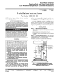
• Demand Defrost Mode (Heat Pump Systems Only)
This unit uses a demand defrost system to remove fiost
froln the outdoor coil during heating operation. The
indoor and outdoor fans are shut off during Defrost
mode. See Fig. 19. For high wall heat pump units, the
electric heat is OFF during Defrost mode.
• Set Back
The Set Back mode timer turns the unit off
when the timer reaches zero minutes. The durations that
can be selected are 1, 2, 3 or 7 hours. After the initial
30 minutes, the user set point shifts approximately 1° F
warmer. This sequence repeats itself every 40 minutes up
to a total of 150 minutes. When Set Back mode is
enabled, the display on the remote controller is dimmed.
• On/Off Timer Mode
The on!off timer will turn the
unit on or offat a user selectable on and offtime (this is
one time event only). The unit will start in the same
mode and at the same selected temperature as when the
system
shut off. If the rooln temperature is not within
approximately 5 F of the set point 40 minutes before
start-up, the unit runs before the user selected on time is
reached to achieve the set point temperature at start-up.
• Automatic Operation Mode for Cooling Only Systems
The unit samples the air in the room. Based on the
room temperature, the unit selects one of the t\_ltowing
modes:
1. Cooling Mode
If the room telnperature is more than
82 F with a preset telnperature of 79 F.
2. Dry Mode
If the room temperature is more than
75 F and less than 82 F with a preset temperature of
77 F.
Microprocessor
Control Operation-This system
is controlled by a microprocessor designed to give optilnum
levels of comfort and operating ei_ciency. The control is located in the indoor unit. To operate the unit, the thctory-supplied
relnote controller is required.
There are 9 (cooling only) or 12 (heat pump) operating
modes (including the offmode) for the unit. Each ll_lodeoperates as follows:
• Off Mode
When the unit is in the Offlnode, all functions (compressor, outdoor tan, indoor fan, and air
sweep) are oft; except the reversing valve (heat pump
only), which will stay energized if the unit was last operated in the Cooling mode.
• Air Circulation Mode (Fan Operation Only)
When
Air Circulation mode is selected, the indoor fan wilt
operate continuously at the selected speed (high,
medium, low, or Auto.). If the Auto. mode is selected,
the indoor tan will operate at low speed. The compressor
and outdoor fan are off. The reversing valve (heat pump
only) will remain in the last operating mode.
• Cooling Mode
When the Cooling mode is selected,
the indoor tan will operate continuously at the selected
speed if the speed is high, medium, or low. If the indoor
fan is in Auto. mode, the tim will change operating
speeds depending on the difference between the room
temperature and the set point. The reversing valve (heat
pmnp only) will be energized. The compressor cannot
run for 3 minutes from the time the system starts up or
for 3 minutes from the time the compressor last operated.
When the temperature of the room is equal to or _eater
than the selected telnperature, the colnpressor and outdoor fan will operate until the room temperature is 2 F
below the set point, and then shut ofl, When the room
temperature is less than the selected telnperature, the
compressor and outdoor tan remain oft'. Indoor Pan runs
according to selected mode.
• Dehumidification
Mode
When the Dehumidification
mode is selected the indoor tan will operate at a speed
and setting selected by the microprocessor. There is no
user interface with this mode.
3. Fan Only Mode
75 F.
If the room temperature is less than
• Automatic Operation Mode for Heat Pump Systems
The operation mode will be determined after 20 seconds of room monitoring (to determine the room temperature and the outdoor air temperature).
• Test Mode
The test mode can be selected by setting
the slide switch on the tan coil unit to TEST position.
The slide switch is located on the front of the unit as
shown in Fig. 20. The fan coil unit will start immediately
(there is no compressor time delay when using Test
mode) in Cooling mode with an infinitely low set point.
15
TheindoortZan
speed
will beatthehighsetting,
andthe
swinglouvers
will beon(moving
upanddo,am).
NOTE:Theunitcmmot
becontrolled
bytheremote
controller
untiltheslideswitch
isreturned
totheREMOTE
position.
or Heating mode according to room telnperature. Emergency operation settings are as follows:
1. Operation mode: AUTO.
2. Fan Speed: AUTO.
3. Cooling set point: 77 F
4. Timer Mode: Continuous
• Emergency Mode
This mode is only to be used if the
remote controller is lost, damaged, or the batteries are
dischaNed. To initiate Emergency mode, manually move
the slide switch on the fan coil unit to the EMER position
(Fig. 20). The unit is automatically operated in Cooling
NOTE: The unit cannot be controlled by the remote controller
until the slide switch is returned to the REMOTE position.
4O
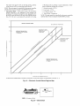
DEFROST REGION THREE
(NO DEFROST
3O
OPERATION)
ADJUSTS IF LONG
DEFROST CYCLE
(MORE THAN
6 MINUTES)
DEFROST REGION TWO
(MINIMUM UNIT RUNTIME
= 6 HOURS*)
ADJUSTS
(LESS THAN
3 MINUTES)
2O
W
_z
CE
ul
O,_
z
ud
o
©
O2
IF SHORT
10
o
o
C2_
k-
o
DEFROST REGION ONE
(MINIMUM UNIT RUN TIME
= 50 MIN.*)
-10
-10
0
10
20
30
OUTDOOR AIR TEMPERATURE (F)
*A defrost will be initiated after 30 minutes of compressor
run time if the outdoor coil temperature
is less than -4 ° E
Fig. 19 -- Electronic Control Defrost Regions Map
TE ST-J
EMER -- Emergency Mode
Fig. 20 -- Slide
16
Switch
_ LR E MOT E
EMER.
40
CLEANING
AND MAINTENANCE
Replace the remote controller batteries when the remote
controller function becomes irregular, or the system no longer
responds to commmlds given close to the unit.
When shutting down the system for an extended period of
time, it is advisable to remove the batteries from the remote
controller.
To avoid the possibility of electric shock, before performing
aaly cleaning and maintenance operations, always turn off
power to the system by pressing the ON/OFF button on the
remote controller. Turn off the outdoor disconnect switch
located near the outdoor unit. It'the indoor unit is on a separate switch, be sure it is also disconnected.
Consult your distributor if any other equipment is turned on
or shows signs of disrupted operation if you use the wireless remote controller, or if the system is mined on or shows signs of
disrupted operation when the remote controller of aaly other
equipment is used.
To Set the Current
For proper system operation, perform the cleaning and
maintenance operations listed in Table 10.
1. Press the [_ button (located on the front of the
remote controller; see Fig. 22) with an instrument
screwdriver or similar small, pointed tool, and the current time indication symbol flashes.
Note that the controller comes preset from the factory
set for 6:00 a.m.
Lubrication -- The indoor-tan automatic air sweep motor,
and the outdoor-tan motor are thctory lubricated and require no
oiling.
To Install or Replace
Batteries
Remote
Time
Controller
2. Set the current time with the hour and minute buttons
on the front of the remote controller (see Fig. 21) while
the current time indication is flashing. Note that a.m.
and p.m. are also indicated as the times are scrolled
through.
Do not drop the remote controller
daanage to the device
may result. Avoid getting the controller wet.
3. When you reach the current time, press [-_ again.
The flashing will stop and the current time will be
reset to the new setting.
NOTE: Betbre replacing the batteries, note that the remote controller signal can be affected if electronic fluorescent lights are
installed nearby. The batteries may not need to be replaced. If
you suspect this is the problem, consult your distributoi:
Batteries should be replaced once a year. Use 2 batteries
(1.5 v, de-type, AAA alkaline batteries). Never use old or
rechaNed batteries together with new ones.
To replace batteries:
1. Slide the battery cover off from the back of the remote
controller. See Fig. 21.
2. Insert the 2 batteries in accordance with the markings
on the remote controller, so that the poles are correct
(+ and 3.
3. Replace the cover securely.
To Remove
and Clean or Replace
Air Filters
Operating your system with dirty air filters may damage the
indoor unit and can also cause reduced cooling perfurmance, intermittent system operation, frost build-up on the
indoor coil, and blown fuses. Inspect and clean or replace
the air filters momhl3'.
TO REMOVE AIR FILTERS
1. Open the tan coil unit front panel (lift). See Fig. 23.
2. Pull the tilters down to remove.
4. Press the _
button on the fiont of the remote usin_
an instrnmen_screwdriver
or similar small, pointed
tool.
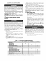
Table 10 -- Cleaning and Maintenance Schedule
TASK
INDOOR
]
MONTHLYI
OUABTEBLY
I YEARLY
UNIT
Clean Air Filters
Clean Drain Pipe
Clean Condensate
X
X
Drain Pan
X
X
Replace Batteries in the Remote Controller
Clean Indoor Unit Front Panel
OUTDOOR
X
UNIT
Clean the Fins From Outside
X
Open the Unit and Clean Fins Inside
Remove Dust From Electrical Parts
X
Check Electrical Connections
Clean Outdoor Fan
X
Check that Outdoor Fan Assembly
Clean Drain Pan
NOTE: Maintenance
X
are Tight
X
X
is Tight
X
procedures for the outdoor unit are in the outdoor unit installation instructions.
17
TO CLEAN OR REPLACE FILTERS
Filters should be
vacuumed and ,a_ashedwith warm water (see Fig. 23). Shake
the tilter to remove any excess ,a_atei; dry it thoroughly, and
replace it by sliding the tilter behind fiont gille until the tilter
snaps in place.
If the filter has bemm to break down or is tom, it needs to
be replaced. Replacement tilters are available through your
distributor.
To Clean Indoor Coil -- To clean the coil, remove the
indoor unit front panel, and vacuum the coil fins. Use care not
to bend or dmnage fins.
To Clean Outdoor
Unit)
Some metal parts and sharp fins of unit coil can cause personal injury during cleaning. Clean coil carefully.
To Clean Indoor Unit Front PanelIf the fiont panel of the unit becomes dirty or smudged, wipe the outside of the
tlront panel with a soft dry cloth. If necessary, use a mild liquid
deteIgent and wipe off carefully with a dry cloth.
To clean the outdoor coil:
1. Remove any dirt or obstruction from the discharge
opening.
2. Use a garden hose to spray water on the coil. Debris
that collects between coil fins inhibits heat transfer
direct the water spray between coil fins to flush out
debris.
When cleaning the fiont panel, NEVER use water hotter
than 105 F, and DO NOT pour water onto the tan coil unit.
Do not use abrasive or petroleum-based cleaners
damage to unit appearance will result.
!
Coil (Outdoor
Cleaning Condensate DrainsClean all drains and
drain pans at the start of each cooling season. Check the flow
by pouring water into the drain.
_T
e_e
TA
_o o
PRESS RST /
REMOVECOVER
INSERT NEW BATTERIES
PRESS
FRONT VIEW
NOTE: Be sure to insert new batteries correctly (as shown),
Fig. 21 -- Installing or Replacing Batteries
HOUR
BUTTON_
---....MINUTE
BUTTON
PRESS TA
FRONT VIEW
Fig. 22 -- Setting The Current Time
REMOVE FILTER
VACUUM CLEAN
NOTE: DO NOT lift grille past its stop point.
Fig. 23 -- Air Filter Maintenance
18
RINSE WITH WATER
SERVICE
System TestsThe system tests listed below are performed continuously by the microprocessor. If a fault is indicated, then the system allows only lhnited operation until the
probleln is resolved. If the problem resolves itsel£ then the
code is cleared and operation resumes.
When servicing unit, turn off all electric power to unit to
avoid shock hazard or injury tiom rotating parts.
THERMISTOR TESTS
Each thermistor is tested tbr high
limit out of range (shorted coMition) and low limit out of range
(open condition). If the thermistor is out of range, the fault stares indicator comes on mid the green LED flashes the appropriate fault code.
Do not vent refrigerant to atmosphere when servicing unit.
Recover reliigerant during system repair or unit relnoval.
THERMISTORS
Proper thermistor location and correct
temperature sensing are ca-iticatto unit operation. Good thennat
contact is also required. Thermistor cable asselnblies are provided with fro1coil units to run between indoor mid outdoor
units. High-voltage mid thermistor cable assemblies should not
touch each other, and cable runs may be extended up to
200 feet. With the unit running, the thermistor integrity may be
checked by measuring the d.c. voltage across the two thermistor connections. Approximate telnperamre is iMicated in
Table 12.
Diagnostic Codes -- This unit is equipped with a microprocessor control that continuously monitors the unit's operation. If an operational fault is detected, a fault is indicated by
the flashing green "UNIT ON" light on the tiont of the t'mlcoil
unit. The control wilt continue to monitor the unit and, if the
coMitions that cause the thult are cleared, the unit wilt return to
normal operation. If the thult code is present for 5 cycles of the
unit, the unit will be locked out and the alarm indicated by the
flashing green "UNIT ON" light on the front of the tan coil
unit.
System
To access the red LED iMicator light, remove the tiont cover of the unit by relnoving the 3 screws holding it in place.
If the red LED indicator light continuously flashes on tbr
one secoM, then off for one secoM, the control is lhnctioning
properly. Table 11 lists the number of quick flashes and the
associated thult. If the system does not operate, and the LED
indicator does not flash, either the power to the control board is
oil; or the control board has tailed.
Table 11 -- System Fault Codes
NO. OF QUICK
LED FLASHES
SYSTEM
FAULT
2
Room Air Thermistor
3
Indoor Coil Thermistor
4
Outdoor Coil Thermistor*
7
Outdoor Air Thermistor*
8
LED -- Light-Emitting
Safeties
and Interlocks
INDOOR FAN FAILURE
If the indoor t'ml rpm shows
greater than 800 rpm for 30 seconds with the tan in the off
mode, then this test indicates ml indoor tan thiture. Also, if the
iMoor tan rpm is greater than 1700 rpm for 30 seconds, then
this test indicates ml indoor tan failure.
COMPRESSOR SHORT-CYCLING PROTECTION
There
is a 3-minute time delay between compressor turning off and
taming back on.
INDOOR COIL FREEZE PROTECTION (Cooling or Dehumidification Mode Only)
If the indoor coil temperature is
less than or equal to 32 F for 10 minutes after the compressor
has started, then the compressor and outdoor tan are mined oil"
The indoor tan continues to run at the user-selected speed until
the indoor coil reaches 44 F. At that time, the colnpressor and
outdoor fan will restart.
INDOOR COIL HIGH-TEMPERATURE
PROTECTION
(Heat Pump Systems Only)
If the indoor coil temperature
is greater than or equal to 135 F, the outdoor fan shuts down.
The outdoor tan will restart automatically when the indoor
coil temperature drops to 120 F.
Indoor Fan Failure
Diode
*Heat pump systems only.
NOTE: If the LED light continuously flashes on for one second, then
off for one second, the control is functioning properly and no fault is
present.
TROUBLESHOOTING
See Table 13 and Fig. 24-27 to assist in troubleshooting the
fan coil units.
19
Table 12 -- Thermistor Properties*
TEMP
(F)
MINIMUM
OHMS
NOMINAL
OHMS
MAXIMUM
OHMS
MINIMUM
THERMISTOR
VOLTS -- DC
NOMINAL
THERMISTOR
VOLTS -- DC
MAXIMUM
THERMISTOR
VOLTS -- DC
-40
303.300
342,700
386,200
4.80
4.82
4.84
-30
211,500
237,276
265,444
4.72
4.75
4.77
-20
149.721
166,689
185,146
4.61
4.65
4.68
-10
107.379
118,776
130,973
4.48
4.52
4.55
0
77,281
85,677
93,867
4.30
4.35
4.40
f0
56,567
62,617
68,205
4.09
4.16
4.21
20
42,661
46,302
50,129
3.86
3.92
3.98
30
32,043
34,580
37,220
3.59
3.66
3.72
32
30,300
32,550
35,120
3.53
3.60
3.66
40
24,061
26,118
27,960
3.28
3.36
3.43
50
18,650
19,900
21,180
2.99
3.05
3.11
60
14,402
15,312
16,219
2.67
2.73
2.79
70
11,247
11,883
12,518
2.36
2.42
2.47
80
8,820
9,299
9,779
2.06
2.11
2.16
g0
6,846
7,339
7,754
1.76
1.83
1.88
100
110
5,487
4,367
5,829
4,667
6,187
4,976
1.52
1.29
1.57
1.34
1.63
1.40
120
3,502
3,760
4,026
1.09
1.14
1.19
130
2,830
3,051
3,281
0.92
0.97
1.02
140
2,300
2,489
2,687
0.77
0.82
0.87
150
1,880
2,045
2,216
0.65
0.69
0.74
160
1,547
1,688
1,836
0.55
0.59
0.63
170
1,280
1,402
1,531
0.46
0.50
0.53
180
1,065
1,170
1,282
0.39
0.42
0.45
190
200
890
748
982
828
1,078
913
0.33
0.28
0.36
0.31
0.39
0.33
210
631
701
766
0.24
0.26
0.28
212
611
678
751
0.23
0.25
0.28
*Circuit volts = 5 vdc.
Table 13 -- Troubleshooting
PROBLEM
Unit Does Not Operate
Insufficient
Cooling
POTENTIAL
SOURCE
Circuit breaker has tripped or fuse is blown
Reset the circuit breaker or replace the fuse.
Power failure
Restart fan coil unit operation when power is
restored.
Voltage is too low
Air filter is blocked with dust
Confirm the available voltage.
Clean the air filter.
Temperature
Check and reset if necessary.
is not set properly
Window(s) and/or door(s) are open
Outdoor unit is obstructed
Close window(s) and door(s).
Remove the obstruction.
Fan speed is too low
Change the fan speed
Operation
mode is set to fan or auto. mode
Air filter is blocked with dust
Temperature
Insufficient
Heating*
Unit Stops During Operation
ACTION
is not set properly
Change to cooling operation or reset temperature
(using remote controller),
Clean the air filter.
Check and reset if necessary.
Close window(s) and door(s).
Window(s) and/or door(s) are open
Outdoor unit is obstructed
Remove the obstruction.
Off timer is operating
Turn off the off timer function.
Room temperature
set point
Normal unit operation.
has reached the programmed
*Heat pump systems only.
2O
_
EATHERPROOF
FUSED DISCONNECTt
PERNEC
_
ii
_
"_- 2 WIRES
_
AIRFLOW
(+) GROUND
_ATER
HEAT PUMP ONLY)
DEV_I_ECE*-"-__
(BIFLOW)t
":'
'
OUTDOOR
UNIT
'; ;'
" .:
INDICATOR
SIGHT GLASSt
_ ..,
THERMISTOR
CABLE*
(COOLING ONL_
5 WIRES (HEAT PUMP)t
ACCURATER_
METERING DEVICE
(INSTALLED AT
UNIT)
2 WIRES
(4
AIRFLOW
CONTROL POWER
PROVIDED INSIDE UNIT
,I--
FUSED DISCONNECTf
S*GNT
j/ -
TOOPEN
_
LEGEND
NEC -"---------.m....._
--
WIRELESS
CONTROLLER*
//
.........
CONDENSATE
DRAIN LINEt
National Electrical Code
Piping
Line Voltage
24 V
Thermistor
_>_"
._"
_
DRAIN (DO NOT
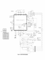
NOTES:
1. All piping must follow standard refrigerant piping techniques.
2. All wiring must comply with the applicable local and national codes.
3. Liquid line need not be insulated. Cooling units only.
4. Wiring and piping shown are general points-of-connection
guides only and are
not intended for a specific installation.
5. Insulate condensate drain if installed in a conditioned space.
*Standard.
1-Field supplied.
Fig. 24 -- Typical Piping and Wiring -- High Wall Systems,
2!
18,000 and 24,000 Btuh
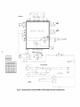
LEGEND
AGING
AS, ASS'Y
C
CAP
CH
CLO
CN
COMP
CT
EMI
FL
FMC
GND
HA
HPS
HS
HTR
IDC Th
IFM
JEM-A
K
LLPS
LPS
LS
ODA Th
ODC Th
OFM
---
--
---
---
AND NOTES FOR FIG. 25-27
For the Burn-In Test (short these terminals)
Assembly
Contactor
Capacitor
Crankcase Heater
Compressor Lockout
Connector
Compressor
Current Transformer
Electromagnetic Interference
Fuse Link
Fan Motor Capacitor
Ground
Home Automation
High-Pressure Switch
Hall (Rpm) Sensor
Heater
Indoor-Coil
Thermistor
Indoor-Fan Temperature
Motor
Japan Electric Manufacturing
Industry Association
Relay
Liquid Low Pressure Switch
Low-Pressure Switch
Limit Switch
Outdoor-Air Thermistor
Outdoor-Coil Thermistor
Outdoor-Fan Motor
OFR
OL
PCB
RA Th
RC
RCV
RVS
SC
SR
ST
STM
TB
TG
TP
TRAN
----------------
Outdoor-Fan Relay
Overload
Printed Circuit Board
Return Air Thermistor
Resistor Capacitor
Receiver
Reversing Valve Solenoid
Start Capacitor
Start Relay
Start Thermistor
Step Motor
Terminal Block
Time Guard
Thermal Protector
Transformer
<_)
Terminal (Marked)
(_)
Terminal (Unmarked)
Q
Splice
[]
Terminal Block
Factory Wiring
Field Control Wiring
Field Power Wiring
Accessory or Optional Wiring
1. If any of the original wire furnished must be replaced, it must be
replaced with type 90 C wire or its equivalent.
2. Wire in accordance with National Electrical Code (NEC) and local
codes.
3. The CLO locks out the compressor to prevent short cycling on compressor overloads and safety devices. Before replacing CLO, check
these devices. A minimum one amp turn is required to hold contacts
closed.
4. Thermistor wiring cable 35 feet long provided with unit.
5. IFM, OFM and compressor have internal thermal protectors.
6. Transformer has a 2 amp thermal fuse on the primary side.
22
018, 024 FANCOIL
CN9
I_
Th_
RA Th
CN7
CNl3
RELAY
Ix3
%0
CHART
COMPRESSOR
REV.
VALVE
OUTDOOR
FAN
THERMISTOR
TEMPERATURE
STEP
MOTOR eL)
K13
Kll
K12
EQUIVALENCE
RESISTANCE
°F
°C
o
95
35
5,500
72
22
11,400
32
0
32,500
STEP
MOTOR (R)
ALL THERMISTORS ARE IDENTICAL
Fig. 25 -- Heat Pump Wiring Diagram
_R_F_
DISPLAY
CNll
PCB AS
CNlO
018 024 FANCOIL
HA
JEM
A
F_
AGING SHORT
rTT_l
r77_
BRN
IDC
CN9
P1
P2
CNll
CN12
CNIO
3N13
CNI8
Th
RA Th
.o#o'#%
_
BLK
3N14
CONTROL PCB ASS'Y
YEL c
.o#&%,
25ov 3,
3N1
BARE
COPPER
BLU
BRN
GRN/YEL
CN3,
I 2 3 4
#
REDBLK
GRN/YEL
3210N4123
J3b
4_wHCTN31
CN3O_
WHT
___RAED
RED
BLUoR G
TB2
COMMON(24VAC)
COMP
_y
FRO
1FR
L R :A PDOAS
THERMISTOR
TEMPERATURE
EQUIVALENCE
RESISTANCE
°F
°O
95
35
5,500
72
22
11,400
32
0
32,500
018, 024 OUTDOOR SECTION
a
TO
OUTDOOR
UNIT
DISCONNECT
20B/230V
1PH 8OHZ
ALL THERMISTORS ARE IDENTICAL
EQUIP
GND
BRN_
Fig. 26 -- Cooling
Only Fan Coil Unit with 38HDC or 538A Cooling
Only Outdoor
Condensing
Unit
DISPLAY
ON11
GRN/YEL_
018.024FAN COIL
POD AS
ON10
HA
JEM A
FT_
AGING SHORT
FY3]
[]q3]
CNE
IOC
Th
Pl
P2
CNll
CNlO
ON12
CN13
ON18
BRN
RA Th
CN14
ON7
PCB ASS" Y
CN1
BLK
034
BARE RED
OOPPER
®
EMI
FILTER
GRN/YEL
ON3
1 2 3 4
CUSE
CABLEDISCONNECT
PROVIDED)
TO UNIT
L f
®
GRN/YEL
•
CND[
ORD
TB2
COMNON(24VAC)
CN31
TIME GUARO TIMING SEQUENCE
3 SEC_
T] T2[__
RUN TIME _
BLACK DENOTES
CLOSED
_5
M[N.
ON30
]
COMP
FMC
BLK
WHT__
_
CONTACTS
R_L3Ay POD AS
THERMISTOR
TEMPERATURE
TO
EQUIVALENCE
_F
_C
Q
95
35
5,500
72
22
11,400
32
0
32,500
C_
YEL_
BLK
BLK_H
YEL
BLU
/
018.
YEL
BLU
THERMISTOR5
ARE IDENTICAL
BLK
OUTDOOR
_SC
_
SECTION
_CLO
BLU_
OFM
O_N_.Y_
_
024
.ST
_BRN__
ALL
OUTDOOR
CONTROL
RESISTANCE
_BLK_
CT
_
EQUIP
GND _
....
_HP5
BRN
Fig. 27--
Cooling
Only Fan Coil Unit with 38HDL or 538J Cooling
TO
I]
OUTDOOR
L]
_BLK_/
v- !
....
I
I[I2
BLK{
C
Only Outdoor Condensing
Unit
I
I
UNIT
WIRING?
I_
J
OI5CONNECT
UNIT
Copyright 2002 Carrier Corporation
Manufacturer reserves the right to discontinue, or change at any time, specifications
PC 111
Catalog No. 534-043
Printed in U.S,A,
or designs without notice and without incurring obligations,
Form 40QN-6SI
Pg 26
9-02
Replaces:
40QN-4SI