1
DC-788
Counting Scale
Version 1.09
Counting Scale
Operation Manual
91685
Contents
1.0
Introduction.................................................................................................................................. 1
1.1 Capacities and Resolutions . . . . . . . . . . . . . . . . . . . . . . . . . . . . . . . . . . . . . . . . . . . . . . . . . . . . . . . 1
1.2 Modes of Operation . . . . . . . . . . . . . . . . . . . . . . . . . . . . . . . . . . . . . . . . . . . . . . . . . . . . . . . . . . . . . 2
1.2.1
Description of Modes of Operation . . . . . . . . . . . . . . . . . . . . . . . . . . . . . . . . . . . . . . . . . . . . . . . . . . . . 2
1.3 Keyboard and Display . . . . . . . . . . . . . . . . . . . . . . . . . . . . . . . . . . . . . . . . . . . . . . . . . . . . . . . . . . . 2
1.3.1
1.3.2
1.3.3
2.0
Installation ................................................................................................................................... 6
2.1
2.2
2.3
2.4
2.5
2.6
2.7
2.8
3.0
Display Specifications . . . . . . . . . . . . . . . . . . . . . . . . . . . . . . . . . . . . . . . . . . . . . . . . . . . . . . . . . . . . . . 2
Indicator Lamps . . . . . . . . . . . . . . . . . . . . . . . . . . . . . . . . . . . . . . . . . . . . . . . . . . . . . . . . . . . . . . . . . . 2
Key Functions . . . . . . . . . . . . . . . . . . . . . . . . . . . . . . . . . . . . . . . . . . . . . . . . . . . . . . . . . . . . . . . . . . . . 3
Unpacking. . . . . . . . . . . . . . . . . . . . . . . . . . . . . . . . . . . . . . . . . . . . . . . . . . . . . . . . . . . . . . . . . . . . .
Repacking. . . . . . . . . . . . . . . . . . . . . . . . . . . . . . . . . . . . . . . . . . . . . . . . . . . . . . . . . . . . . . . . . . . . .
Setting Up. . . . . . . . . . . . . . . . . . . . . . . . . . . . . . . . . . . . . . . . . . . . . . . . . . . . . . . . . . . . . . . . . . . . .
Powering Up the DC-788 . . . . . . . . . . . . . . . . . . . . . . . . . . . . . . . . . . . . . . . . . . . . . . . . . . . . . . . . .
6
7
7
7
2.4.1
2.4.2
2.4.3
2.4.4
7
8
9
9
AC Power Source . . . . . . . . . . . . . . . . . . . . . . . . . . . . . . . . . . . . . . . . . . . . . . . . . . . . . . . . . . . . . . . . .
DC Battery Pack Replacement/Installation. . . . . . . . . . . . . . . . . . . . . . . . . . . . . . . . . . . . . . . . . . . . . . .
Battery Charging . . . . . . . . . . . . . . . . . . . . . . . . . . . . . . . . . . . . . . . . . . . . . . . . . . . . . . . . . . . . . . . . . .
Start-Up Screens . . . . . . . . . . . . . . . . . . . . . . . . . . . . . . . . . . . . . . . . . . . . . . . . . . . . . . . . . . . . . . . . .
Setting the Date . . . . . . . . . . . . . . . . . . . . . . . . . . . . . . . . . . . . . . . . . . . . . . . . . . . . . . . . . . . . . . .
Replacement Parts. . . . . . . . . . . . . . . . . . . . . . . . . . . . . . . . . . . . . . . . . . . . . . . . . . . . . . . . . . . . .
Block Diagram of Electrical Connections . . . . . . . . . . . . . . . . . . . . . . . . . . . . . . . . . . . . . . . . . . .
Physical Layout of Electrical Connections . . . . . . . . . . . . . . . . . . . . . . . . . . . . . . . . . . . . . . . . . .
10
10
11
11
Configuration Settings ............................................................................................................... 12
3.1 Configuring Specification 141 and 142 Settings from the Scale Keyboard . . . . . . . . . . . . . . . . 12
3.1.1
3.1.2
4.0
5.0
Customer Specification (141 Settings) . . . . . . . . . . . . . . . . . . . . . . . . . . . . . . . . . . . . . . . . . . . . . . . . . 12
Weight and Measurement Specifications (142 Settings). . . . . . . . . . . . . . . . . . . . . . . . . . . . . . . . . . . . 15
Calibration ................................................................................................................................. 19
Scale Operations........................................................................................................................ 21
5.1
5.2
5.3
5.4
Counting Scale Accuracy and the TEP (Teraoka Error Prediction) Mode . . . . . . . . . . . . . . . . . .
Weight Unit Switching . . . . . . . . . . . . . . . . . . . . . . . . . . . . . . . . . . . . . . . . . . . . . . . . . . . . . . . . . .
Toggling Between Scales . . . . . . . . . . . . . . . . . . . . . . . . . . . . . . . . . . . . . . . . . . . . . . . . . . . . . . .
Setting Tare Weights in Weighing Mode. . . . . . . . . . . . . . . . . . . . . . . . . . . . . . . . . . . . . . . . . . . .
21
22
22
22
5.4.1
5.4.2
5.4.3
5.4.4
22
22
22
23
One Touch Tare (When the Tare Weight is Unknown) . . . . . . . . . . . . . . . . . . . . . . . . . . . . . . . . . . . . .
Digital Tare (When Tare Weight is Known in Advance) . . . . . . . . . . . . . . . . . . . . . . . . . . . . . . . . . . . . .
Tare Addition or Subtraction . . . . . . . . . . . . . . . . . . . . . . . . . . . . . . . . . . . . . . . . . . . . . . . . . . . . . . . .
Tare Override . . . . . . . . . . . . . . . . . . . . . . . . . . . . . . . . . . . . . . . . . . . . . . . . . . . . . . . . . . . . . . . . . . .
5.5 Entering Unit Weights . . . . . . . . . . . . . . . . . . . . . . . . . . . . . . . . . . . . . . . . . . . . . . . . . . . . . . . . . . 23
5.5.1
5.5.2
Unit Weight Operation by Sampling . . . . . . . . . . . . . . . . . . . . . . . . . . . . . . . . . . . . . . . . . . . . . . . . . . . 23
Unit Weight Operation by Key Entry. . . . . . . . . . . . . . . . . . . . . . . . . . . . . . . . . . . . . . . . . . . . . . . . . . . 24
5.6 Setting a Lot Number . . . . . . . . . . . . . . . . . . . . . . . . . . . . . . . . . . . . . . . . . . . . . . . . . . . . . . . . . . . 24
5.7 Setting a Sequence Number . . . . . . . . . . . . . . . . . . . . . . . . . . . . . . . . . . . . . . . . . . . . . . . . . . . . . 24
5.8 Operations Without Recalling an Item Code . . . . . . . . . . . . . . . . . . . . . . . . . . . . . . . . . . . . . . . . 25
5.8.1
5.8.2
5.8.3
A Single Counting Operation - Without Recalling an Item Code . . . . . . . . . . . . . . . . . . . . . . . . . . . . . . 25
Part Accumulation or Subtraction and Negative Counting - Without Recalling an Item Code . . . . . . . . 25
Setting a Temporary Lot Number, Part Number or Part Name - Without Recalling an Item Code. . . . . 27
5.9 Using Item Codes in Weighing Mode . . . . . . . . . . . . . . . . . . . . . . . . . . . . . . . . . . . . . . . . . . . . . . 28
5.9.1
5.9.2
5.9.3
5.9.4
5.9.5
Recalling Item Codes using Item Code Number . . . . . . . . . . . . . . . . . . . . . . . . . . . . . . . . . . . . . . . . .
View Item Information . . . . . . . . . . . . . . . . . . . . . . . . . . . . . . . . . . . . . . . . . . . . . . . . . . . . . . . . . . . . .
Adding Parts To and Subtracting Parts From Inventory . . . . . . . . . . . . . . . . . . . . . . . . . . . . . . . . . . .
Tare Override . . . . . . . . . . . . . . . . . . . . . . . . . . . . . . . . . . . . . . . . . . . . . . . . . . . . . . . . . . . . . . . . . . .
Delete Item Memory . . . . . . . . . . . . . . . . . . . . . . . . . . . . . . . . . . . . . . . . . . . . . . . . . . . . . . . . . . . . . .
28
28
28
30
30
6.0
Scale Programming ................................................................................................................... 31
6.1 Checking Memory Status . . . . . . . . . . . . . . . . . . . . . . . . . . . . . . . . . . . . . . . . . . . . . . . . . . . . . . . 31
6.2 Review the Item Code Numbers Programmed in Memory . . . . . . . . . . . . . . . . . . . . . . . . . . . . . 32
6.3 Program Item Code, Tare Weight, Unit Weight, Inventory, Part Number, Part Name, Lot Number,
Setpoint 1 and Setpoint 2 32
6.4 View Item Code Programming in Memory . . . . . . . . . . . . . . . . . . . . . . . . . . . . . . . . . . . . . . . . . . 34
6.5 Program a General Setpoint . . . . . . . . . . . . . . . . . . . . . . . . . . . . . . . . . . . . . . . . . . . . . . . . . . . . . 34
6.6 Resetting the Sequence Number to Zero. . . . . . . . . . . . . . . . . . . . . . . . . . . . . . . . . . . . . . . . . . . 35
6.7 Programming a Temporary Lot Number, Part Number or Part Name . . . . . . . . . . . . . . . . . . . . 35
6.7.1
6.7.2
6.7.3
Change the Lot Number Temporarily . . . . . . . . . . . . . . . . . . . . . . . . . . . . . . . . . . . . . . . . . . . . . . . . . 36
Change the Part Number Temporarily . . . . . . . . . . . . . . . . . . . . . . . . . . . . . . . . . . . . . . . . . . . . . . . . . 36
Change the Part Name Temporarily . . . . . . . . . . . . . . . . . . . . . . . . . . . . . . . . . . . . . . . . . . . . . . . . . . 36
6.8 Delete Item Memory . . . . . . . . . . . . . . . . . . . . . . . . . . . . . . . . . . . . . . . . . . . . . . . . . . . . . . . . . . . 36
6.8.1
6.8.2
6.8.3
6.8.4
6.8.5
6.8.6
6.8.7
6.8.8
7.0
Delete All Item Codes in Memory . . . . . . . . . . . . . . . . . . . . . . . . . . . . . . . . . . . . . . . . . . . . . . . . . . . .
Delete a Specific Item Code . . . . . . . . . . . . . . . . . . . . . . . . . . . . . . . . . . . . . . . . . . . . . . . . . . . . . . . .
Delete All Inventory Values from Memory. . . . . . . . . . . . . . . . . . . . . . . . . . . . . . . . . . . . . . . . . . . . . . .
Delete All Unit Weight Values from Memory. . . . . . . . . . . . . . . . . . . . . . . . . . . . . . . . . . . . . . . . . . . . .
Delete All Tare Weight Values From Memory . . . . . . . . . . . . . . . . . . . . . . . . . . . . . . . . . . . . . . . . . . . .
Delete all Part Numbers From Memory . . . . . . . . . . . . . . . . . . . . . . . . . . . . . . . . . . . . . . . . . . . . . . . .
Delete All Setpoint Data in Memory . . . . . . . . . . . . . . . . . . . . . . . . . . . . . . . . . . . . . . . . . . . . . . . . . . .
Delete All Part Names in Memory . . . . . . . . . . . . . . . . . . . . . . . . . . . . . . . . . . . . . . . . . . . . . . . . . . . .
36
36
37
37
38
38
39
39
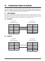
External Devices: Printers, PCs and Scales.............................................................................. 41
7.1 Printer Connection . . . . . . . . . . . . . . . . . . . . . . . . . . . . . . . . . . . . . . . . . . . . . . . . . . . . . . . . . . . . 41
7.1.1
7.1.2
7.1.3
Zebra LP2844. . . . . . . . . . . . . . . . . . . . . . . . . . . . . . . . . . . . . . . . . . . . . . . . . . . . . . . . . . . . . . . . . . . 41
DIGI GP460R . . . . . . . . . . . . . . . . . . . . . . . . . . . . . . . . . . . . . . . . . . . . . . . . . . . . . . . . . . . . . . . . . . . 41
Epson TM-U210 and TM-U290, Star SP2320 and SP298 . . . . . . . . . . . . . . . . . . . . . . . . . . . . . . . . . 42
7.2 Printer Label Formats . . . . . . . . . . . . . . . . . . . . . . . . . . . . . . . . . . . . . . . . . . . . . . . . . . . . . . . . . . 42
7.2.1
7.2.2
7.2.3
7.2.4
7.2.5
7.2.6
No Printer . . . . . . . . . . . . . . . . . . . . . . . . . . . . . . . . . . . . . . . . . . . . . . . . . . . . . . . . . . . . . . . . . . . . . .
DIGI GP460R Label Printer . . . . . . . . . . . . . . . . . . . . . . . . . . . . . . . . . . . . . . . . . . . . . . . . . . . . . . . . .
ZEBRA LP2844 Barcode Printer . . . . . . . . . . . . . . . . . . . . . . . . . . . . . . . . . . . . . . . . . . . . . . . . . . . . .
Epson TMU200 or Star SP2320 Tape Printer . . . . . . . . . . . . . . . . . . . . . . . . . . . . . . . . . . . . . . . . . . .
Epson TM-U295 or Star SP298 Ticket Printers . . . . . . . . . . . . . . . . . . . . . . . . . . . . . . . . . . . . . . . . . .
DIGI TVP1000 Barcode Printer . . . . . . . . . . . . . . . . . . . . . . . . . . . . . . . . . . . . . . . . . . . . . . . . . . . . . .
42
42
42
44
44
44
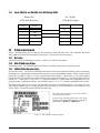
7.3 Connecting to a PC . . . . . . . . . . . . . . . . . . . . . . . . . . . . . . . . . . . . . . . . . . . . . . . . . . . . . . . . . . . . 45
7.3.1
7.3.2
7.3.3
7.3.4
7.3.5
Setting the Scale Specifications for Communication to a PC . . . . . . . . . . . . . . . . . . . . . . . . . . . . . . . .
Communication Method . . . . . . . . . . . . . . . . . . . . . . . . . . . . . . . . . . . . . . . . . . . . . . . . . . . . . . . . . . .
Pin Assignments . . . . . . . . . . . . . . . . . . . . . . . . . . . . . . . . . . . . . . . . . . . . . . . . . . . . . . . . . . . . . . . . .
Characters That Can Be Transmitted by RS-232C . . . . . . . . . . . . . . . . . . . . . . . . . . . . . . . . . . . . . . .
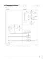
RS-232C Data Transmission Formats . . . . . . . . . . . . . . . . . . . . . . . . . . . . . . . . . . . . . . . . . . . . . . . . .
45
45
48
48
49
7.4 Remote Scale Channel . . . . . . . . . . . . . . . . . . . . . . . . . . . . . . . . . . . . . . . . . . . . . . . . . . . . . . . . . 51
7.4.1
7.4.2
8.0
Setting the Specifications for Scale 2 . . . . . . . . . . . . . . . . . . . . . . . . . . . . . . . . . . . . . . . . . . . . . . . . . 52
Remote Platforms Available . . . . . . . . . . . . . . . . . . . . . . . . . . . . . . . . . . . . . . . . . . . . . . . . . . . . . . . . 53
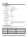
Appendix .................................................................................................................................... 54
8.1 DC-788 Specifications. . . . . . . . . . . . . . . . . . . . . . . . . . . . . . . . . . . . . . . . . . . . . . . . . . . . . . . . . . 54
8.2 DC-788 Error Message List. . . . . . . . . . . . . . . . . . . . . . . . . . . . . . . . . . . . . . . . . . . . . . . . . . . . . . 54
8.3 ASCII Code Table . . . . . . . . . . . . . . . . . . . . . . . . . . . . . . . . . . . . . . . . . . . . . . . . . . . . . . . . . . . . . 55
9.0
DC-788 Limited Warranty........................................................................................................... 57
5FDIOJDBMUSBJOJOHTFNJOBSTBSFBWBJMBCMFUISPVHI3JDF-BLF8FJHIJOH4ZTUFNT
$PVSTFEFTDSJQUJPOTBOEEBUFTDBOCFWJFXFEBUXXXSJDFMBLFDPNPSPCUBJOFE
CZDBMMJOHBOEBTLJOHGPSUIFUSBJOJOHEFQBSUNFOU
© 2007 Rice Lake Weighing Systems. All rights reserved. Printed in the United States of America.
Specifications subject to change without notice.
Version 1.09, July 2007
About This Manual
This manual contains operating procedures for the DC-788 counting scale and provides the user with all the
information necessary for setup and operation. It is organized based on the procedures you will likely follow
when setting up and using your counting scale. This manual applies to Version 1.09 of the DC-788 counting scale
series.
#AUTION
Some procedures described in this manual require work inside the scale base. These procedures are to
be performed by qualified service personnel only.
Authorized distributors and their employees can view or download this manual from the
DIGI distributor site at www.DigiScales.com.
1.0
Introduction
The DC-788 is a low cost counting scale that offers practical solutions for a full range of counting applications.
Its counting resolution of 1/1,000,000 gives you maximum counting precision and accuracy. Its high-visibility
red LCD display enables operators to easily see weights and quantities. With the ability to store an item code,
part number, part name, lot number, tare weight, unit weight, inventory quantity and setpoint value for 100 of
your pieces, parts, or items, the DC-788 is a self-contained inventory system. The RS-232 output allows you to
connect to a printer or PC, while the remote scale channel lets you add another weighing platform. When
portability is required, choose the battery operation option of the DC-788 for over 24 hours of continuous use in
mobile workstations, outdoor applications, and rental fleets. It’s waterproof keyboard and splash-proof housing
make the DC-788 rugged enough to operate reliably in many environments and withstand transport from one
area of the plant to another or from one business to the next.
1.1
Capacities and Resolutions
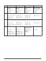
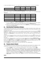
Table 1-1 lists the scale capacities, minimum graduations, and tare ranges for all models of the DC-788 counting
scales. The display resolution is 1/10,000 with an internal or counting resolution of 1/1,000,000. Units are
selectable from lb to kg from the keyboard.
DC-788 Single Scale
DC-788 Capacity
Minimum Graduation
Tare Range
500 g
0.1 g (1e = 200IR)
0-249.9 g
1 kg
0.2 g (1e = 200IR)
0 - 0.4998 kg
2.5 kg
0.5 g (1e = 200IR)
0 - 0.9995 kg
5 kg
1 g (1e = 200IR)
0 - 2.499 kg
10 kg
2 g (1e = 200IR
0 - 9.998 kg
25 kg
5 g (1e = 200IR
0 - 9.995 kg
1 lb
0.0001 lb (1e = 100IR)
0 - 0.9998 lb
2 lb
0.0002 lb (1e = 100IR)
0 - 0.0095 lb
5 lb
0.0005 lb (1e = 100IR)
0 - 9.995 lb
10 lb
0.001 lb (1e = 100IR)
0 - 9.999 lb
20 lb
0.002 lb (1e = 100IR)
0 - 9.998 lb
50 lb
0.005 lb (1e = 100IR)
0 - 9.995 lb
Table 1-1. DC-788 Capacities, Minimum Graduations and Tare Ranges
Introduction
1
1.2
Modes of Operation
1.2.1
Description of Modes of Operation
The DC-788 has three modes of operation:
• Weighing Mode –
where all weighing, counting and printing operations take place.
• Programming Mode – where item and inventory data can be programmed into the memory of the scale.
The display will show ProG to indicate that you are the Programming Mode.
• Maintenance Mode where your DIGI dealer can set specifications, perform scale calibration and
other maintenance functions.
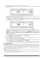
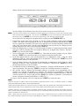
1.3
Keyboard and Display
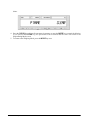
Figure 1-1 shows the DC-788 console with its indicator lamps, the function keyboard and the numeric keypad.
Annunciators are described in Section 1.3.2. Section 1.3.3 describes the DC-788 keyboard and keypad.
Figure 1-1. DC-788 Display
1.3.1
Display Specifications
Tare weight display
5 digits
Weight display
5 digits
Unit weight display
5 digits
Quantity display
7 digits
Table 1-2. DC-788 Display Specifications
1.3.2
Indicator Lamps
Table 1-3 shows a list of the indicator lamps that the DC-788 uses to provide additional information about the
value being displayed. The indicator lamps are illuminated when the specific function is being performed.
Indicator Lamp
0
Function or Meaning
On when the gross weight is zero and is stable
NET
On when the display shows net weight (when a tare weight is entered or recalled)
KG
On when the item is being weighed in kg units with [kg/lb] key pressed
LB
On when the item is being weighed in lb units with [kg/lb] key pressed
RECOMP
On when unit weight recomputing is possible
INSUFF
On when the net weight is below the specified percentage of scale capacity
Table 1-3. DC-788 Indicator Lamps and Function
2
DC-788 Operation Manual
Indicator Lamp
Function or Meaning
scale 1
On when scale 1 is in use (the built-in platform)
scale 2
On when scale 2 is in use (an external platform)
prog
On when the scale is in Programming Mode
wt/1000
On when the unit weight is being displayed per 1000 pcs.
apw
On when the unit weight is displayed per one piece (average piece weight).
∑
Quantity is accumulating
out
Item out of item inventory (subtracting from inventory)
in
Item in to item inventory (adding to inventory)
batt
Battery warning when weak and needs charging (only for rechargeable battery type)
charge
Battery charging (only for rechargeable battery type)
Table 1-3. DC-788 Indicator Lamps and Function
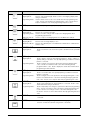
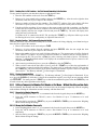
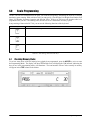
1.3.3
Key Functions
The DC-788 features many functions for managing inventory information and scale operation. Figure 1-2 shows
the two key-sheet layouts and Table 1-4 lists the keys and key functions of the DC-788 keyboard and keypad.
Figure 1-2. Key Sheet Layout
Some keys have different functions depending on what mode or function you are in.
Key
to
Description
ON/OFF -
Turns the scale display on or off
Numeric keys -
Used to enter numeric values. When using the scale, first enter a numeric
value, then press the appropriate function key.
DECIMAL key -
Used to set the decimal point.
Table 1-4. DC-788 Key Functions
Introduction
3
Key
Description
CLEAR key.
Weighing Mode -
Used to clear the Unit Weight. Used to return to the weighing display when
doing accumulation.
Programming Mode - Used to delete an Item Code or associated value when programming item
codes. Used to Cancel input in programming SPC codes. Used to Reset
Sequence Number to zero when programming Sequence Codes.
PCS key -
Used for computing unit weight by sampling.
TARE key.
Weighing Mode Used to set or clear the tare value.
Programming Mode - Used to store SPC changes and escape to the Weighing Mode when
programming specifications.
Maintenance Mode - Used to escape to the Weighing Mode from the Maintenance Mode.
REZERO key.
Weighing Mode Maintenance Mode -
Used to reset the weight display to zero.
Used to enter different parts of the Maintenance Mode when combined with
numeric codes.
CODE/IN-OUT key.
Weighing Mode -
Used to recall Item Codes from memory and to determine inventory IN/OUT
status.
- (Minus) key.
Weighing Mode -
Programming Mode -
Used to delete a character entered during operations. Used to subtract a
quantity during accumulation. Also prompts printing of a label if an external
printer is connected.
Used to navigate to the previous specification when programming SPC
codes. Used to move between item codes when reviewing already
programmed item codes. Used to display the current date and time when
programming the date and time.
+ (Plus) key.
Weighing Mode Programming Mode -
* PRINT key Weighing Mode Programming Mode -
Used to accumulate data. Also prompts printing of a label if an external
printer is connected.
Used to navigate to the next specification when programming SPC codes.
Used to move between item codes when reviewing already programmed
item codes. Used to store set point data when programming item codes.
Print/Data setting key.
Used to print a label when an external printer is connected. Used to clear
TOTAL data when doing accumulation.
Used to temporarily store changes to specification data when programming
SPCs. Used to store data to Item Code memory when programming Item
Codes. Used to store changes to item codes when editing Item Code
information. Used to store the date and time when programming Date and
Time.
SCALE key.
Used to select between Scale 1 and Scale 2 if an external scale is
connected.
MODE key -
Used to enter the programming mode from the weighing mode. Used to
enter the command mode when using numeric commands.
Table 1-4. DC-788 Key Functions
4
DC-788 Operation Manual
Key
Description
KG/LB/INVENT key- Used to convert the weighing units between kg and lb. Also used to toggle
on and off whether inventory stored in memory is being affected by the
current transaction.
UNIT WEIGHT key - Used to set the unit weight and display all digits of the unit weight.
Table 1-4. DC-788 Key Functions
Introduction
5
2.0
Installation
This section describes the procedure for the installation and setup of the DC-788 counting scale.
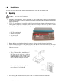
2.1
Unpacking
#AUTION
Do not turn scale upside down. Always work with scale on its side! Damage to the load cell can occur if
the scale is turned upside down.
1. Immediately after unpacking, visually inspect the DC-788 counting scale to ensure all components are
included and undamaged. If any were damaged in shipment, notify Rice Lake Weighing Systems and the
shipper immediately.
2. The DC-788 counting scale is carefully packed for protection during shipping. After opening the box,
remove all the components. Check the insides of the box carefully to make sure you have all of the
pieces. The package should include the following:
•
•
•
•
DC-788 counting scale
Stainless steel platter
AC power cord
Operation Manual
3. Remove the bag protecting the scale and the protective film covering the front panel and platter.
4. Seat the stainless steel platter on the platter supports, with the four corner pins inserted into the corner
rubber stops. For DC-788 scales with a 2 lb. capacity, the scale must first be unlocked using the
following procedure.
•
Take off the two Nuts A and Screw C.
Then remove Screws D, Plate C and Nut
B. Then turn the scale on its side to
complete removal of the locking screw.
REMINDER: Do not turn the scale upside
down as this can damage the load cells.
•
Remove Nut F and then Screw E. Then
take off Screw G and Washer H.
5. After ensuring that all parts are present, store the DC-788 scale box for possible future use.
6
DC-788 Operation Manual
2.2
Repacking
If the DC-788 counting scale must be returned for modification, calibration or repair, it must be properly packed
with sufficient cushioning materials. Whenever possible, use the original carton when shipping the DC-788.
Damage caused by improper packaging is not covered by the warranty.
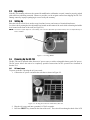
2.3
Setting Up
Place the scale on a solid, level surface away from fans, breezes, and sources of electrical interference.
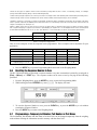
Level the scale by turning the four adjustable legs located on the bottom of the scale while referencing the bubble
level located on the front of the scale (see Figure 2-1).
NOTE: To ensure a higher degree of scale stability, turn in all four adjustable legs before leveling. Turn out adjustable legs to
level as needed.
Figure 2-1. Leveling Bubble
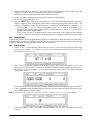
2.4
Powering Up the DC-788
The DC-788 can be operated either from an AC power source or with a rechargeable battery pack (DC power).
The DC power allows the unit to be completely portable. Instructions for DC operation are contained in
Section 2.4.2.
2.4.1
AC Power Source
To power up the DC-788 using the AC power cord:
1. Connect the AC power cord under the scale base as shown in Figure 2-2.
Figure 2-2. AC Plug-in Location on Underside of DC-788
2. Plug the AC power cord into a grounded 115 VAC receptacle.
3. Press the ON/OFF key located on the front of the scale. The scale will run through a check of the LCD
Installation
7
display’s segments. How thorough the segment check is depends on the setting of SPC 20, Bit 2. The
default is 1: Normal (For further instructions on how to set the scale’s specifications, see Section 3.1.2):
• If SPC 20, Bit 2 is set to 0: Fast, the scale display’s 888’s for 1.5 seconds, then blanks for 1.5
seconds. It then displays 888’s again followed by a blank display for another 1.5 seconds before
going into the normal weighing mode.
• If SPC 20, Bit 2 is set to 1: Normal, the scale’s display will test the LCD segments for each numeral
from 0 to 9, asterisks, decimal points and annunciators before going into the normal weighing mode.
4. Once the scale is on, the time interval before the scale will automatically power itself off, if there no key
is pressed and no weight is placed on the platter, is determined by SPC 00- Auto Power-Off Function.
The default is 0000: Disabled. (For further instructions on how to set the scale’s specifications, see
Section 3.1.1)
2.4.2
DC Battery Pack Replacement/Installation
An optional DC battery pack (PN 88933) for the DC-788 is available and can be purchased from RLWS to ship
with the scale or retrofit in the field. The rechargeable 6V 5.0 AH battery pack allows for up to 24 hours of scale
use without an AC power supply. It is located in the bottom of the scale base. Use the following procedure to
install or replace the battery pack.
1. Unplug the scale from power source.
2. Place scale its left side.
#AUTION
Do not turn the scale upside down. Always work with the scale on its side. Damage to the load cell can
occur if the scale is turned upside down.
3. Unscrew the two thumb screws holding the battery compartment door closed.
Figure 2-3. Thumb Screws for Battery Compartment
4. Unscrew the two screws holding on the battery holding bracket and remove the bracket.
Figure 2-4. Removing Battery Bracket.
5. Remove the battery from its compartment, then disconnect the black (-) and red (+) electrical leads from
the battery.
8
DC-788 Operation Manual
6. Attach the red lead to the positive (+) terminal of the new DC battery pack, and the black lead to the
negative (-) terminal. Place new DC battery pack in battery compartment.
7. Replace the battery holding bracket and fasten it with its two screws.
8. Replace the battery compartment door and fasten it with its two thumb screws.
9. Put the scale back upright on its feet.
10. Press the ON/OFF key located on the front of the scale. The scale will run through a check of the LCD
display’s segments. How thorough the segment check is depends on the setting of SPC 20, Bit 2. The
default is 1: Normal (For further instructions on how to set the scale’s specifications, see Section 3.1.2):
• If SPC 20, Bit 2 is set to 0: Fast, the scale display’s 888’s for 1.5 seconds, then blanks for 1.5
seconds. It then displays 888’s again followed by a blank display for another 1.5 seconds before
going into the normal weighing mode.
• If SPC 20, Bit 2 is set to 1: Normal, the scale’s display will test the LCD segments for each numeral
from 0 to 9, asterisks, decimal points and annunciators before going into the normal weighing mode.
2.4.3
Battery Charging
A fully charged battery allows for approximately 24 hours of continuous use. When the battery is low the battery
indicator light will light up. It will take approximately 8-10 hours to fully recharge a battery that has been
completely dissipated. To charge the battery, plug in the AC power cord.
2.4.4
Start-Up Screens
1. If SPC 20, Bit 3 - Version Display When Power On is set to 0: Allow, the scale will display the current
version of the firmware it is using as it powers up (For further instructions on how to set the
specifications, see Section 3.1.2).
2. After a test of the different elements of the display, the scale takes you to the stand-by screen in the
Weighing Mode. SPC 20, Bit 2 - Selection of Segment-Check Style controls whether the startup test of
the segments is Fast or Standard. At the stand-by screen the TARE, WEIGHT, UNIT WEIGHT and PCS
displays show zeroes.
From this stand-by screen all of the basic weighing, counting and inventory operations can be performed
3. If there is anything on the platform(s) and it exceeds the scale start range, the display will show the error
message OF indicating “weight overflow”.
Note: The Initial Start Range settings are controlled by SPC 20, Bit 1. The default setting is 0: ± 10% OF FULL SCALE.
If this error appears, remove the weight from the platform and the scale will continue its startup
sequence.
Installation
9
2.5
Setting the Date
Without a power supply, the DC-788 will reset the time and date. For units that do have battery power, the time
and date can be supported for up to 20 days in the OFF status without any AC power supply. After 20 days the
unit will reset itself.
The procedure below can also be used to adjust the time when moving from Standard to Daylight Savings Time
or when the scale is moved to a new facility in a different time zone.
NOTE: SPC 04, Bits 3 and 2 - ORDER OF MONTH, DATE AND YEAR allows you to set the format for the date that you prefer
the scale to display. The default is 00: Month/Date/Year. To change these specifications, see Section 3.1.2).
1.
2.
3.
4.
5.
6.
7.
8.
2.6
Press the MODE key twice until the display shows ProG.
Press the – (Minus) key to display the current time and date.
Press the – (Minus) key again.
Using the keyboard, enter the desired date i.e.: [0] [6] [0] [9] [0] [5] for June 9th, 2005.
Press the * PRINT key to store the date setting.
Using the keyboard, enter the time, i.e.: [1] [5] [0] [5]
Press the * PRINT key to store the time setting
Press the MODE key to exit the weighing mode.
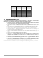
Replacement Parts
The following list contains the part numbers and descriptions of replacement parts available for the DC-788
counting scale.
RLWS Part Number
Description
88933
Battery Pack, 6 V, 5.0AH lead acid
89994
Keysheet, 16 keys, DC-788
89997
Keysheet, 8 keys, DC-788
89999
Keyboard
90152
Mainboard for DC-788
90153
Loadcell, 2 lb
90154
Loadcell, 10 lbs
90155
Loadcell, 20 lbs
90156
Loadcell, 50 lbs
90157
Loadcell, 100 lbs
90188
Top cover
90160
Support platter
90171
Platter cover, 10 lb to 100 lb
65956
Platter cover, 2 lb
Table 2-1. DC-788 Replacement Parts
10
DC-788 Operation Manual
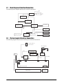
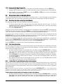
2.7
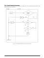
Block Diagram of Electrical Connections
The following block diagram illustrates the electrical connections.
7"%
1PXFS4FMFDUPS
7
3FHVMBUPS
5SBOTGPSNFS
$IBSHF$POUSPMMFS
3FDIBSHBCMF
#BUUFSZ7PIN
.JDSPDPOUSPMMFS
)4FSJFT
-$%.PEVMF
34$
*OUFSGBDF
-PBEDFMM
&FQSPN$
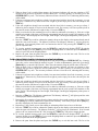
2.8
,FZQBE
"%$POWFSUPS
-PBEDFMM
Physical Layout of Electrical Connections
The following diagram illustrates the actual layout of electrical connections.
1JO'FNBMF"NQIFOPM
GPS&YUFSOBM-PBEDFMM
"$3FDFQUBDMF
-PBEDFMM
3FDIBSHBCMF#BUUFSZ
70IN
34
*OUFSGBDF
5SBOTGPSNFS
"%#PBSE
45#
185
'VTF
"7
4$8%
$/
1
$/
1
$/
1
$/
1
$/
1
%$.BJO#PBSE45#
0QFSBUPS-$%
1
$/
,FZCPBSE
45#
Installation
11
3.0
Configuration Settings
This section presents the setup and configuration of the DC-788 counting scale to be used specifically by
distributors and service technicians. Configuring these specifications allow you to tailor the DC-788 to your
specific applications.
Setting the specifications allows you to modify the functionality of the DC-788. Use the tables in this section to
view the options you can modify.
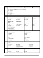
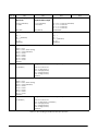
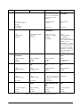
3.1
Configuring Specification 141 and 142 Settings from the Scale Keyboard
The following tables list the DC-788 specifications, their corresponding default values, and the other possible
values to which they can be programmed. The default values are set at the factory when the scale is shipped.
SPC 0 through SPC 19 (Table 3-1) are customer specifications and use the 141 access code, while SPC 20
through SPC 35 (Table 3-2) are weight and measurement specifications, and use the 142 access code
In programming specifications, the + (Plus) and – (Minus) keys allow you to move to the next or previous
specification. The CLEAR key cancels any input you have made. The * PRINT key temporarily stores to
memory any changes you have made. The TARE key saves to memory the changes you have made and returns
you to the weighing mode. Note also that when programming specifications, only the 0 and 1 keys on the
numeric keypad are enabled, since those are the only valid entries.
3.1.1
Customer Specification (141 Settings)
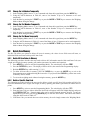
1. To configure customer specifications, press and hold the REZERO key and enter 141 using the numeric
keypad. The first SPC code is displayed.
The Weight display shows what specification you are in (in this case, SPC00). The Unit Weight display
shows how this specification is currently programmed (Bit 3 = 0; Bit 2 = 0; Bit 1 = 0, and Bit 0 = 1 in this
example, while the PCS display will show any changes you enter.
If this is the SPC that you want to modify, enter the new setting from the numeric keypad and press the *
PRINT key to enter the change into temporary memory and move to the next SPC code.
2. Use the + (plus) and – (minus) keys to scroll through the specifications until you find the one you want.
Then make your changes per the instructions in Step 1.
3. To change another SPC code before exiting, repeat Steps 1 and 2.
4. To save all the changed SPC settings currently in temporary memory and exit to the Weighing Mode,
press the TARE key.
12
DC-788 Operation Manual
SPEC No.
00
Bit 3
Bit 2
Bit 1
Bit 0
Auto Power-off Function (for no key operation and weighing operation)
0000: Auto power-off disable when scale is not in use (DEFAULT)
0001: 3 minutes
0010: 10 minutes
0011: 30 minutes
1011: 1 hour
0101: 3 hours
0110 ~ 1111 - not used
(SP1_OFFT)
01
0: Not used
02
Buzzer
Error Alarm
Set Point Alarm
Not Used
0: On (DEFAULT)
1: Off
(SP1_BUZZ)
0: On (DEFAULT)
1: Off
(SP1_ALARM)
0: On (DEFAULT)
1: Off
(SP1_PALARM)
0: (DEFAULT)
Unit weight base per
1000PCS or 1 PCS
display
Sampling time for unit
weight calculation
Negative Counting
Re-zero Function
0: 1000PCS (DEFAULT)
1: 1PCS
(SP1_UWID)
Note: When SPEC 27 Gross Mode is set to 0:
Allow, the scale remains in
UW/1000, regardless of
how this SPEC 3 is set.
See note under SPEC 27.
0: 10 times
1: 5 times (DEFAULT)
(SP1_STFUWC)
0: Allow (DEFAULT)
1: Inhibit
(SP1_NCOUNT)
0: Allow (DEFAULT)
1: Inhibit
(SP_RZF)
03
04
05
06
07
Order of month, date and year
Set Point Type
00: MM/DD/YY (DEFAULT)
01: DD/MM/YY
10: YY/MM/DD
11: Not used
(SP1_DATEO)
00: % quantity (DEFAULT)
01: % weight
10: Quantity
11: Weight
(SP1_SPT)
Function of RS-232 Interface
Extrent of insufficient samples
00: PC
01: Printer (DEFAULT)
10: Not used
11: Not used
(SP1_RS232IF)
00: 0.1% (DEFAULT)
01: 0.2%
10: 0.0%
11: Not used
(SP1_INSUFFRG)
RTS/CTS Handshaking of
RS-232C
Baud Rate of RS-232C
0: On
1: Off (DEFAULT)
(SP1_RTS)
000: 1200 bps
001: 2400 bps
010: 4800 bps
011: 9600 bps (DEFAULT)
(SP1_BAUD)
Stop bit of RS-232C
Data length of RS-232C
Parity of RS-232C
0: 1 bit (DEFAULT)
1: 2 bit
(SP1_STOP)
0: 7 bit
1: 8 bit (DEFAULT)
(SP1_DLEN)
00: None (DEFAULT)
01: Odd
(SP1_PAR)
100: 19200 bps
101: Not used
110: Not used
111: Not used
10: Even
11: Not used
Table 3-1. DC-788 (141) Settings
Configuration Settings
13
SPEC No.
08
Bit 3
Bit 2
Bit 1
Bit 0
RS-232C PC Protocol
0000: Inhibit data transfer (DEFAULT)
0001: Standard stream type (continuous output
0010: Standard manual type
0011: Stand command type
0100~ 1111: Not used
(SP1MODE)
09
External Printer Type
0000: No Printer (DEFAULT)
0001: DIGI GP460R Label Printer
0010: Zebra LP2844 Bar Code Printer
0011: Epson TMU200 or Star SP2320 Tape Printers
0100: Epson TM295 or Star SP298 Ticket Printers
0101: TVP1000 Bar Code Printer
(SP1PRINTER)
10
11
12
13
Interval of Time Out Error of RS-232
Transmission Condition
of RS-232
00: 1 Second
01: 3 Seconds (DEFAULT)
10: 5 Seconds
11: 10 Seconds
(SP1TIME)
0: Weight Stable (DEFAULT) 0: No (DEFAULT)
1: Unconditional
1: Yes
(SP1_COND)
(SP1_APAR)
Tare Weight in Text of
RS-232
Unit Weight in Text of
RS-232
Gross Weight in Text of
RS-232
Quantity in Text of
RS-232
0: No
1: Yes (DEFAULT)
(SP1_TW)
0: No
1: Yes (DEFAULT)
(SP1_UW)
0: No
1: Yes (DEFAULT)
(SP1_GW)
0: No
1: Yes (DEFAULT)
(SP1_TP)
Date & Time in Text of
RS-232
Parts Information in Text
of RS-232:
Header Code in Text of
RS-232
Weight Range of Data
Output
0: No
1: Yes (DEFAULT)
(SP1_DTIME)
0: Include Parts Information 0: No
1: Include Only ID Code
1: Yes (DEFAULT)
(Output like DC-180.
(SP1_HEAD)
Requires a setpoint value to
be entered to work)
Print When Pressing the +
or - Key
External Printer Print Format
0: No (DEFAULT)
1: Yes
000: Default Format (DEFAULT)
001: Customer Format 1
010: Customer Format 2
~
111: Customer Format 7
(SP1PRINTER)
(SP1_PRTK) (*V1.09)
Table 3-1. DC-788 (141) Settings
14
Additional Parity Code in
Text of RS-232
DC-788 Operation Manual
0: Always (DEFAULT)
1: Over 20e
(SP1_MINWTL)
SPEC No.
14
15
Bit 3
Bit 2
Bit 1
Bit 0
Clear Unit Weight When
Swap Scale
Rezero When Swap Scale Auto Scale Switching
Zero Display
0: No (DEFAULT)
1: Yes
0: No (DEFAULT)
1: Yes
0: No (DEFAULT)
1: Yes
(SP1_UC) (*V1.06)
(SP1_RZ) (*V.106)
(SP1_ASS) (*V1.07)
0: Display 0 With ‘/’
1: Display 0 Without ‘/’
(DEFAULT)
(SP1_DIS0) (*V1.10)
Display “MEM EXIST”
message reminding you
that there is an
accumulation in memory
Clear TARE Weight When
Swapping Scales
Scale Number in Text of
RS-232
0: No
1: Yes (DEFAULT)
0: No (DEFAULT)
1: Yes
0: No
1: Yes (DEFAULT)
Number of Setpoints
0: 2 Setpoints (Default)
1: 3 Setpoints
(SP1_SPN) (v1.10)
(SP1_MEXIST) (V1.10)
16 - 19
Not Used
Table 3-1. DC-788 (141) Settings
3.1.2
Weight and Measurement Specifications (142 Settings)
To make changes to the Weight and Measurement Specifications, the span switch must be on. (For instructions
on how to turn the span switch on, see Section 4.0.)
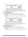
1. To configure customer specifications, press and hold the REZERO key and enter 142 using the numeric
keypad. The first SPC code is displayed.
The Weight display shows what specification you are in (in this case, SPC20). The Unit Weight display
shows how this specification is currently programmed (Bit 3 = 1; Bit 2 = 0; Bit 1 = 0, and Bit 0 = 0),
while the PCS display will show any changes you enter.
If this is the SPC that you want to modify, enter the new setting from the numeric keypad and press the *
PRINT key to enter the change into temporary memory and move to the next SPC code.
2. Use the + (Plus) and – (Minus) keys to scroll through the specifications until you find the one you want.
Then make your changes per the instructions in Step 1.
3. To change another SPC code before exiting, repeat Steps 1 and 2.
4. To save all the changed SPC settings currently in temporary memory and exit to the Weighing Mode,
press the TARE key.
Configuration Settings
15
SPEC No.
20
21
22
Bit 3
Bit 2
Bit 1
Version Display When
Power On
Selection of
Segment-Check Style
Start Range
0: Allow (DEFAULT)
1: Inhibit
0: Fast (DEFAULT)
1: Standard
(SP_VER)
(SP_SEGCK)
00: ±10% of Full Scale (DEFAULT)
01: ± 5% of Full Scale
10: ± 3% of Full Scale
11: ± 2% of Full Scale
(SPSRANGE)
Minimum Display (Scale 1)
Minimum Display (Scale 2)
00: 1
01: 2 (DEFAULT)
10: 5
11: 10
(SPMINID)
00: 1
01: 2
10: 5 (DEFAULT)
11: 10
SPMINID1)
Selection of Resolution (Scale 1)
0000: 1/2500
0001: 1/5000 (NTEP Setting)
0010: 1/10000 (DEFAULT)
0011: 1/15000
0100: 1/20000
0101: 1/25000
0110: 1/30000
0111: 1/12500
(SPRES)
23
24
Not Used
Weight Decimal Point Position (Scale 1)
0: (DEFAULT)
000: No Decimal Point
001: 1st Digit (0000.0)
010: 2nd Digit (000.00)
011: 3rd Digit (00.000)
100: 4th Digit (0.0000)
(SPWPT)
Selection of Resolution (Scale 2)
0000: 1/2500
0001: 1/5000 (NTEP Setting)
0010: 1/10000 (DEFAULT)
0011: 1/15000
0100: 1/20000
0101: 1/25000
0110: 1/30000
0111: 1/12500
(SPRES1)
25
Not Used
Weight Decimal Point Position (Scale 2)
0: (DEFAULT)
000: No Decimal Point
001: 1st Digit (0000.0) (DEFAULT)
010: 2nd Digit (000.00)
011: 3rd Digit (00.000)
100: 4th Digit (0.0000)
(SPWPT1)
Table 3-2. DC-788 Weight and Measurement Specifications
16
DC-788 Operation Manual
Bit 0
SPEC No.
26
27
28
29
30
31
Bit 3
Bit 2
Bit 1
Bit 0
Weight Stability Conditions
2nd Scale
Please note that the scale
switch is not activated until
the 2nd scale has been
calibrated.
IR Mode Protected by
Span Switch
00: Loose
01: Normal (DEFAULT)
10: Tight
11: Stringent
(SPWTATABC)
0: Inhibit (DEFAULT)
1: Enable
0: No (DEFAULT)
1: Yes
(SP_SCALET)
(SP_SPSW)
Weight Unit Base
Type of Decimal Point
Negative Weight
Display Mask
Gross Mode
0: kg
1: lb (DEFAULT)
(SPBASE)
0: .(Standard) (DEFAULT)
1: ,(Europe)
(SP_DPF)
0: Minus Gross > 9e
1: Minus Gross Weight
(DEFAULT)
(SP_NMASK)
0: Allow
1: Inhibit (DEFAULT)
(SP_GROSSM)
Note: When the Gross
Mode is enabled, it disables
the ability to switch
between lb/kg or to switch
to APW because the lb/kg
key is used for the gross
mode. When Gross Mode
is enabled, the scale stays
in UW/1000 regardless of
how SPEC 3 is set.
Manual Tare
Cancellation
Tare Subtraction
Tare Accumulation
Auto Tare Clear When
Rezero
0: Allow (DEFAULT)
1: Inhibit
(SP_MTC)
0: Allow (DEFAULT)
1: Inhibit
(SP_TS)
0: Allow (DEFAULT)
1: Inhbit
(SP_TA)
0: Allow
1: Inhibit (DEFAULT)
(SP_AUTOT)
Digital Tare
Accumulation When
Tare
Zero Tracking When
Tare
Weight Reset When
Tare
0: Allow
1: Inhibit (DEFAULT)
(SP_DT)
0: Allow
1: Inhibit (DEFAULT)
(SP_ACCT)
0: Allow (DEFAULT)
1: Inhibit
(SP_ZTT)
0: Allow (DEFAULT)
1: Inhibit
(SP_WR)
Tare Auto Clear
Unit Weight Auto Clear
Auto Clear Condition
Not Used
0: Allow
1: Inhibit (DEFAULT)
0: Allow
1: Inhibit (DEFAULT)
(SP_TAUTO)
(SP_UAUTO)
0: >=Gross 21e & >=Net 5e 0: (DEFAULT)
1: >=Net 1e & Quantity Not
0 (DEFAULT)
(SP_AUTOCC)
Accumulation
Accumulation Number
Display
WT Data
Synchronization (+ key
only)
Accumulation Display
Style
0: 0: Allow (DEFAULT)
1: Inhibit
(SP_ACC)
0: Allow (DEFAULT)
1: Inhibit
(SP_ANO)
0: Allow (DEFAULT)
1: Inhibit
(SP_WDS)
0: “Total” (DEFAULT)
1: “Add”
(SP_ADS)
Table 3-2. DC-788 Weight and Measurement Specifications
Configuration Settings
17
SPEC No.
Bit 3
Bit 2
Bit 1
Bit 0
32
Exit From Accumulation
Mode After 15 Second
Time Out
Exit From Acculumation
Mode When Weight
Change
Quantity Accumulation
Without Removing
Weight
Quantity Accumulation
Without Changing
Weight (for >= ±10e)
0: Allow (DEFAULT)
1: Inhibit
(SP_EA15)
0: Allow (DEFAULT)
1: Inhibit
(SP_EAWC)
0: Allow (DEFAULT)
1: Inhibit
(SP_QARW)
0: Allow (DEFAULT)
1: Inhibit
(SP_QACW)
1000: 0.40 ~ 0.46
1001: 0.46 ~ 0.53
1010: 0.53 ~ 0.61
1011: 0.61 ~ 0.71
1100: 0.71 ~ 0.82
1101: 0.82 ~ 0.95
33
Loadcell Sensitivity Selection mV/V (1st Scale)
0000: 0.95 ~ 1.09 (Default)
0001: 1.09 ~ 1.27
0010: 1.27 ~ 1.46
0011: 1.46 ~ 1.69
(SPSST)
34
35
0100: 1,69 ~ 1.95
0101: 1.95 ~ 2.25
0110: 2.25 ~ 2.59
0111: 2.59 ~ 3.00
Loadcell Sensitivity Selection mV/V (2nd Scale)
RLWS recommends a setting of 0000 for bench scales and 0011 for floor scales connected as a second scale.
0000: 0.95 ~ 1.09
0001: 1.09 ~ 1.27
0010: 1.27 ~ 1.46
0011: 1.46 ~ 1.69 (Default)
(SPSST1)
0100: 1,69 ~ 1.95
0101: 1.95 ~ 2.25
0110: 2.25 ~ 2.59
0111: 2.59 ~ 3.00
1000: 0.40 ~ 0.46
1001: 0.46 ~ 0.53
1010: 0.53 ~ 0.61
1011: 0.61 ~ 0.71
1100: 0.71 ~ 0.82
1101: 0.82 ~ 0.95
1st Scale Weight Unit
2nd Scale Weight Unit
Negative Weight
Display Mask Range
Not Used
0: kg (DEFAULT)
1: g
(SP_GBASE1)
NOTE: Units for Scale 1
should be set to be the
same as the units on Scale
2 (See SPEC 35, Bit 2)
0: kg (DEFAULT)
1: g
(SP_GBASE2)
NOTE: Units for Scale 2
should be set to be the
same as the units on Scale
1 (See SPEC 35, Bit 3)
0: Minus Gross > 9e
1: Minus Gross >20e
(DEFAULT)
(SP_NMRG)
0: (DEFAULT)
Table 3-2. DC-788 Weight and Measurement Specifications
18
DC-788 Operation Manual
4.0
Calibration
The DC-788 counting scale is a high-precision instrument. Although the scale needs very little maintenance, you
may want to check the calibration after every month or so of normal usage. To do this you will need to have a test
weight of approximately the total capacity of the scale (i.e. a 10 lb weight if you have a 10 lb capacity scale).
After the scale is initially installed, put the weight on the platform and record the weight displayed. Then every
month or so put the same weight on the scale and verify that it still reads the same.
Many facilities have a technician come in and check their units with certified test weights four times a year. If
you are ISO certified, you will want to check to see if your certification specifies more stringent requirements in
order to stay in compliance. Your DIGI scale dealer has the calibrated test weights, expertise and experience to
perform this task for you as well as to check other operating parameters of your scale and help you effectively
integrate scales into your operations. If you do not know who your local DIGI dealer is, call us at
1-715-736-0002 and we will help you find someone who can provide you with on-site support.
Follow the instructions below to calibrate your DC-788 scale to ensure its continued accuracy.
NOTE: You can exit the Maintenance Mode and return to the Weighing Mode at any time by pressing the TARE key. If you
have a remote scale attached to the DC-788, you must first set the SPECs for that remote scale before beginning the calibration
process.
1. Turn the scale on, then press the span switch to reset it. (See Figure 4-1 below.)
Figure 4-1. Location of Span Switch
2. The scale will display the model number, firmware version number and the message S ON indicating that
the Span Switch is currently on.
3. While pressing the REZERO key, enter 8715 from the numeric keypad to enter the calibration mode.
Calibration
19
4. The scale display will confirm that you are in the Calibration Mode.
5. You can select which scale you are calibrating, Scale 1 or Scale 2, by pressing the SCALE key. (If a 2nd
scale is not installed and set in the specifications, pressing the SCALE key has no effect.) If you have
not yet set up the remote scale in the specifications, press the TARE key to exit the calibration process
and and set the specifications. Then power down the scale to commit the changes to the scale’s memory
before returning to calibration. (For information on setting specifications, see “Configuration Settings”
on page 12.)
6. Make sure that there is no weight on the platform of the scale you are calibrating and press the * PRINT
key. The scale will flash briefly as it searches for the zero point and then will display it.
7. Place a reference weight on the platform. It is preferable to calibrate the scale using a weight equal to the
full capacity of the scale (i.e. a 5 lb weight for 5 lb capacity scale, etc.) If the reference weight is not
equal to the full capacity of the scale, it must at least be greater than 10% of the full scale capacity.
If the reference weight is equal to the full capacity of the scale, press the * PRINT key. If the reference
weight is less than the full capacity of the scale, enter the value of the weight placed on the platter using
the numeric keys before pressing the * PRINT key. The weight you enter will appear in the Weight
display.
8. The display will flash briefly again as the span settings for calibration of the scale are being temporarily
saved. Then the display will return to the weighing mode with the calibrated weight showing in the
Weight window..
9. To exit the Maintenance Mode and save your calibration, power down your DC-788 scale. To exit the
Maintenance Mode and return to the Weighing Mode without saving your calibration, press the TARE
key.
20
DC-788 Operation Manual
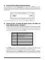
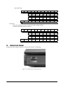
5.0
Scale Operations
The following sections contain detailed operator instructions for the DC-530 counting scale (see Figure 5-1).
Included are instructions on how to switch between scale platforms, how to enter tare weights, how to enter unit
weights, and how to perform counting operations both in the regular Counting Mode and the TEP (Teraoka Error
Prediction) Mode.
Figure 5-1. DC-788 Counting Scale
5.1
Counting Scale Accuracy and the TEP (Teraoka Error Prediction) Mode
Counting scale accuracy is primarily determined by the following factors:
• Sample size (number of pieces)
• Total sample size as a percentage of full scale capacity
• Piece-to-piece weight variation
As a general rule when determining sample size of fairly uniform pieces, the larger the sample size the greater the
total sample weight, therefore, the better the counting accuracy. Selecting the smallest capacity scale that can
obtain the highest counting resolution should be considered, but should not sacrifice the capacity required for the
heaviest container of parts. For this kind of application, a scale like the DC-530 with an extra scale channel is
often the best selection.
There is a direct relationship between piece-to-piece weight variation (non-uniformity) and counting accuracy.
Therefore, elimination of the piece-to-piece weight variations can be accomplished by:
1. Isolating the sample used to calculate the unit weight and use the same sample to re-check the scale.
2. Recalculating the unit weight from lot-to-lot of parts. Parts manufactured on one machine may vary
slightly from another machine relative to weight.
3. Tightening the manufacturing tolerances on the parts reduces piece weight variations and increases count
accuracy.
Parts can vary greatly in their value. With parts of lesser value per piece, the extra sampling and time involved in
trying to achieve 100% accuracy as opposed to 99.5% may not be cost-effective. However, with high value
items 100% accuracy is vital. To address this need, the DC-530 provides you with two counting modes: Regular
Counting Mode and TEP (Teraoka Error Prediction) Mode. Regular Counting Mode offers you the same
ultra-high-precision that all DIGI products are noted for. When you have high-value items, TEP Mode walks you
through a more extensive sampling process from which the scale calculates and displays the number of parts that
can be counted at a time with no counting error.
Scale Operations
21
5.2
Weight Unit Switching
The weight units displayed can be changed between Kg and Lb during weighing operations by pressing the kg/lb
key. The appropriate annunicator will light. SPC27 - Base Weight Units sets the default weight unit to Kgs or
Lbs. If you are using more than one scale, SPC35 sets the weighing units for the 1st and 2nd scales. (For further
instructions on how to set the specifications, see Section 3.1.2)
5.3
Toggling Between Scales
To toggle between Scales 1 and 2, press the SCALE key. The indicator lamp for the appropriate scale lights on
the display.
NOTE: This function is available only when SPC26 - 2nd Scale is enabled. (For further instructions on how to set the
specifications, see Section 3.1.2)
5.4
Setting Tare Weights in Weighing Mode
This section will describe the different tare-related operations you can perform from the weighing mode. Tare
weight can be set by one touch tare using the TARE key or, if the value is known ahead of time, can be entered
digitally using the digital tare function. Tare addition and subtraction can also be done digitally or by using the
TARE key. Finally, an existing tare stored with an Item Code can be overridden temporarily in the Weighing
Mode if needed.
Note: The following SPC codes must be set properly to allow these operations before continuing: SPC 28, Bit 1 - MANUAL
TARE CANCELLATION sets whether or not the tare weight can be cancelled from the keyboard. SPC 28 also controls whether
TARE SUBTRACTION (Bit 2) and TARE ACCUMULATION (Bit 1) are allowed or inhibited and whether AUTO TARE CLEAR WHEN
REZERO (Bit 0) takes place or not. SPC 29 controls whether the scale allows DIGITAL TARE entry (Bit 3), whether the scale can
do ACCUMULATION WHEN TARE (Bit 2), if there will be ZERO TRACKING WHEN TARE (Bit 1) and WEIGHT RESET WHEN
TARE (Bit 0). SPC 30 sets whether or not TARE AUTO CLEAR is activated (Bit 3). (For further instructions on how to set the
specifications, see Section 3.1.2)
5.4.1
One Touch Tare (When the Tare Weight is Unknown)
1. While in the weighing mode, place a bin, box or other weight to be tared out on the platform.
2. Press the TARE key to subtract the tare weight. The Net annuciator will light up, the Weight display
should now show 0 and the tare weight will show in the Tare display.
3. If you remove the tare weight from the platform, the tare weight will show as a negative weight in the
weight window and the Net annunciator will remain lit.
Note: This tare weight will be overridden by the weight stored with an Item Code when you call up an Item Code.
4. To clear this tare weight and return to the Weighing Mode, press the TARE key again. The net
annunciator will not longer be lit.
5.4.2 Digital Tare (When Tare Weight is Known in Advance)
1. While at the stand-by screen, enter the known tare weight by using the numeric keypad.
2. Press the TARE key to subtract the tare weight. The Net annunciator will light up and the tare weight
will be displayed in the weight display.
Note: This tare weight will be overridden by the weight stored with an Item Code when you call up an Item Code.
3. To clear this tare weight and return to the Weighing Mode, press the TARE key again. The net
annunciator will no longer be lit.
Note: For digital tare entry, the decimal must be in the appropriate place as it would be displayed in the weight display. For
example,.250 would be entered as 0.250, not.250. The weight display shows weight entered with a negative sign indicating that
it is a tare weight.
5.4.3 Tare Addition or Subtraction
Two tares can be accumulated or subtracted using the TARE key as well. Tare weights cannot be accumulated or
subtracted by digital entry.
Note: SPC 28, Bits 2 and 1 must be set to 00 to enable Tare Accumulation and Tare Subtraction. (For further
instructions on how to set the specifications, see Section 3.1.2)
1. Place the container, box or item to be tared on the platform and press the TARE key. The weight display
should show 0, the Net annunicator will illuminate and the tare weight will appear in the Tare display.
22
DC-788 Operation Manual
2. Place another tare weight on the platform and press the TARE key again. This will add the two tare
weights together (Tare Addition).
3. Tare weights can be subtracted individually by removing one from the platform and pressing the TARE
key again. To clear all the tare weights and return to the Weighing Mode, remove all the tare weights and
press the TARE key. The Net annunicator will no longer be lit.
5.4.4
Tare Override
For instructions on how to temporarily override a tare that is called up with an Item Code, please see
Section 5.9.4.
5.5
Entering Unit Weights
Entering unit weights can be done either by sampling, as presented in Section 5.5.1, or by key entry as described
in Section 5.5.2.
NOTES: SPC 05 - EXTENT OF INSUFFICIENT SAMPLES controls unit weight sampling. The default setting for the SPC is 00:
0.1 percent.
SPC 14, Bit 3 - CLEAR UNIT WEIGHT WHEN SWAP SCALE sets whether the unit weight determined by sampling is
automatically transferred from Scale 1 to Scale 2 or is cleared when you transfer scales. SPC 14, Bit 1 - AUTO SCALE
SWITCHING, sets . When you have a procedure that involves sampling an item’s unit weight on the DC-788’s built-in
platform and then want to go immediately to weighing and counting boxes or bins on a floor scale or other external
scale, set SPC 14 to 1: YES. If the external Scale 2 is not necessarily going to be used for weighing the same item as is
being sampled on Scale 1, set SPC 14 to 0: NO.
SPC 03 - UNIT WEIGHT BASE PER 1000PCS OR 1PCS controls whether the unit weight is displayed per 1000 pieces
or per 1 piece. The default settings for this SPC is 0: 1000 pieces.
(For further instructions on how to set the specifications, see Section 3.1.1)
Unit Weight per 1000 Pieces vs. Unit Weight per 1 Piece
The scale’s internal microprocessor calculates unit weights to 7 or 8 decimal places. However, the scale display
generally can only show Unit Weight to 5 characters. If this Unit Weight is recorded from the scale display and
entered by key entry, this can introduce errors in the Unit Weight and consequently in the counts. This error
increases as the Unit Weight of the parts being counted decreases.
Example: A sample of 10 zener diodes is placed on the scale. The Unit Weight is computed by the scale to be
0.0006536 lbs. However, the scale has a 5 character display for Unit Weight so the scale can only display.0065 as
the Unit Weight. If this Unit Weight were recorded and keyboard entered in future counting operations, the
resulting error would be:
00065
=.55%
.0006536
On the other hand, with entry of the Unit Weight as “weight per 1000 pieces” the decimal place is, in effect,
moved three places to the right, allowing 3 more decimal places of accuracy. In this example, the entry would be
made as 0.6536 per 1000 pieces, eliminating the error.
As a practical note, entering unit weights per 1000 pieces also lessens the chances of entering the wrong number
of zeros when keying in weights with many leading zeros. Misentry of unit weights is a common cause of
inaccurate counting.
When might you want to use unit weight per 1 piece? Generally in one of two cases:
1. If you are working with other existing systems or procedures that are already set up to record unit weight
per piece (inventory systems, labeling requirements, etc).
2. If the unit weight or your pieces is more than 100 lbs, as in the case of some castings, engine parts and
the like. When the unit weight is over 100 lbs, the number of digits in the scale’s Quantity display will
not be able to fully display counts of more than 100 pieces.
5.5.1
Unit Weight Operation by Sampling
Unit weight operation by sampling is accomplished by placing a 10 piece sample on the scale and then pressing
the PCS key. The scale calculates a unit weight based on the capacity of the scale compared to the weight of the
sample. If you wish to use a sample of more than 10 pieces, place the sample on the scale, then input the sample
size before pressing the PCS key.
Scale Operations
23
If the sample size is insufficient to give an accurate unit weight, no unit weight will be displayed, the INSUFF
lamp will be illuminated and you have the following options:
• You can add pieces to the sample (keeping track of how many you add) until the INSUFF lamp goes
out Key in the new total sample quantity and press the PCS key. The scale will compute and
display the unit weight.
• The scale will prompt you to add enough pieces to bring the sample up a weight that allows
calculation of a more accurate unit weight The weight will appear in the Weight display, the word
ADD in the Unit Weight display and the number of pieces to be added in the PCS display.
Add exactly the number of pieces requested (the PCS display will go down to 0) and press the PCS
key. The scale will compute and display the unit weight and the INSUFF lamp will go out.
You can ignore or override the INSUFF indicator by pressing the PCS key again without adding more pieces to
the sample. However, it may affect counting accuracy to use a Unit Weight calculated on the basis of an
insufficient sample. If you do press the PCS key again, the scale will compute and display the unit weight based
on the original sample you gave it.
If the RECOMP indicator is lit, the accuracy of the unit weight computation can be improved by adding
approximately double the number of pieces currently on the scale and pressing the PCS key again. The scale will
flash as it recomputes the unit weight, after which it will display the new Unit Weight.
•
5.5.2
Unit Weight Operation by Key Entry
Unit weight operation by key entry is accomplished by using the numeric keypad to enter the known value of the
unit weight and then pressing the UNIT WEIGHT key. An example of unit weight operation by key entry is
shown below:
1. With the display in the weighing mode, enter the known unit weight using the keyboard, for example,
200.00.
2. Press UNIT WEIGHT key to enter the unit weight.
3. Place a 2 lb. weight on the scale. The scale displays the quantity for the weight placed on the scale, for
example, the weight display reads 2.000, the unit weight display reads 200.00, and the quantity display
reads 10).
4. Press the CLEAR key to clear the Unit Weight.
5.6
Setting a Lot Number
Lot numbers can be attached to Item Codes when programming item codes into memory. For instructions on
how to set a lot number, see Section 6.3.
A Lot Number which is not associated with a specific item code can also be set temporarily in the Weighing
Mode. If the DC-788 is connected to an external printer or PC, this Lot Number will appear on labels and
receipts or be output to the PC as part of the data string. For instructions on how to set a temporary Lot Number
not associated with an Item Code, see Section 5.8.3.7 below.
5.7
Setting a Sequence Number
The scale can maintain and print a sequence number to aid in transaction tracking and auditing. If the sequence
number is set to “0”, no sequence number will be incremented or tracked. Otherwise the sequence number will
automatically increment by 1 each time a label is printed by pressing the + (Plus), - (Minus), or * PRINT keys.
24
DC-788 Operation Manual
1. At the stand-by screen, press the MODE key twice to enter the Programming Mode.
2. Press and hold the REZERO key while entering [.] [.] [7]. The scale will go to the Sequence Number
Reset screen.
3. To save the new sequence number and exit, press the * PRINT key. To exit without saving the new
sequence number, press the CLEAR key twice.
5.8
Operations Without Recalling an Item Code
The following sections describe ways to carry out operations without having to recall the Item codes.
5.8.1 A Single Counting Operation - Without Recalling an Item Code
At times you may want to perform a weighing and counting operation without recalling an Item Code from
memory. This can be done from the keyboard in the Weighing Mode.
1. Place a 10 piece sample on the scale and press the PIECES key or enter the unit weight from the
numeric keypad and press the UNIT WEIGHT key. The display will flash briefly, then return to normal.
2. To set a tare value, enter the tare from the numeric keypad and press the TARE key or place the container
to be tared on the platter and press the TARE key.
3. Place the product to be weighed and counted on the platter. The total weight and pieces count will be
displayed. If a printer is connected to the DC-788, you can print a label with the data by pressing the *
PRINT key.
4. To perform another weighing and counting operation, remove the product from the scale platter and
press the CLEAR key.
5.8.2
Part Accumulation or Subtraction and Negative Counting - Without Recalling an Item Code
The DC-788 has the capability to acquire the total number of parts using the accumulation or reduction function
of the scale (similar to the add/subtract functions of a calculator).
5.8.2.2 Part Accumulation or Subtraction
To find the total accumulated quantity of similar containers filled with parts, use the accumulation procedure
detailed below. This does not affect the inventory quantity for this item in the scale’s memory. To add or subtract
from inventory, see Section 5.9.3.
1. Enter the unit weight of the pieces (if known) or conduct a sampling process (Section 5.5.1) to determine
the unit weight of the pieces. Press the PCS key.
2. Enter the known tare weight, or place an empty container on the scale to perform tare function
(Section 5.4). Press the TARE key.
NOTE: If SPC 3, Bit 1 - Negative Counting is set to 0: Allow, a quantity of pieces may be displayed if a tare is entered with no
weight on the scale. (For more information on how to set customer specifications, see Section 3.1.1.)
3. Place container 1 (full of parts) on the scale.
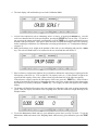
4. Press the + (Plus) key to store the total in container 1. The Memory annunicator ∑ is now illuminated.
The weight display briefly shows totAL 1 and the quantity display shows the total pieces in the first
container.
Note: If the DC-788 is connected to a printer or PC, the data will be printed or outputted each time the + (plus), - (minus) or *
PRINT keys are pressed. If SPC 32, Bit 3 - Exit From Accumulation Mode After 15 Sec Time Out is set to 0: Allow, the display will
return to the weighing mode automatically after 15 seconds. If it is set to 1: Inhibit, you must press the CLEAR key to return to the
weight display. (For more information on how to set the Weight and Measurement specifications, see Section 3.1.2.)
Scale Operations
25
5. Remove container 1 and place container 2 (full of parts) on the scale.
6. Press the + (Plus) key (Total 2 is equal to container 1 plus container 2) The Memory indicator ∑ will be
illuminated.
7. Continue with the remainder of the containers to be counted. The total number of parts stored in all the
containers will be stored in the accumulation register.
8. To subtract pieces from the accumulation, place the container to be subtracted on the platform and press
the - (Minus) key. The display will show CORR and the number of pieces being subtracted. The
Memory indicator ∑ will continue to be illuminated.
9.
10.
11.
12.
13.
14.
Wait for the Total screen to clear and return to the Weighing Mode or press the CLEAR key.
When done with accumulation and subtraction, remove all products from the platter and press the
CLEAR key to clear the Unit Weight. (Note: If you try to press the CLEAR key while there is data in the
accumulation register, you will get an error message which says MEM EXIST. You must press the *
PRINT key to clear the accumulation register before the CLEAR key can be used to clear any unit
weight data on the display.
Press the + (Plus) key to display the accumulated total when the Unit Weight is zero. Wait for the Total
screen to clear and return to the Weighing Mode or press the CLEAR key.
Press the TARE key to clear the Tare Weight.
Press the + (Plus) key to display the total accumulation data. Wait for the Total screen to clear and
return to the Weighing Mode or press the CLEAR key.
Enter [3] [6] from the keyboard and press the - (Minus) key to subtract the data. Wait for the Total
screen to clear and return to the Weighing Mode or press the CLEAR key.
Press the * PRINT key to clear the accumulation register. The Memory indicator ∑ will no longer be lit.
If the DC-788 is connected to a printer or a PC, the total accumulation data will be printed or output.
5.8.2.3 Negative Counting
Just as you can count by adding parts to the scale, you can also count by removing parts from the scale. This is
called “negative counting” because a negative weight is displayed while counting. Contrary to what may seem
intuitively logical, you do not use the (-) key to do negative counting. The (-) key is only used to delete an entry
in accumulation mode that you want to erase. This procedure does not affect the inventory quantity for this item
stored in the scale. To reduce inventory, see Section 5.9.3.
NOTE: To utilize the negative counting feature, SPC 3, Bit 1 - Negative Counting must be set to “0: ALLOW”. (For information
on setting Customer specifications, see Section 3.1.1.)
There are two ways to do this depending on whether at the end you want to see the total amount remaining in the
container or the total amount removed from the container.
26
DC-788 Operation Manual
5.8.2.4 Counting Out of a Full Container - See Total Amount Remaining in the Container
To carry out this operation you must know the tare weight ahead of time.
1. Place the full container on the scale. Press the TARE key.
2. Remove a 10 piece sample to the container and press the PIECES key. After the unit weight has been
calculated, return the 10 piece sample to the container.
3. Remove a number of parts from the container. The QUANTITY window of the scale display will show
the number of pieces you have removed. This process can be repeated as many times as desired.
4. If at the end of the procedure, if you want to see how many remain in the bin or container, you first have
to know the tare weight of the bin or container. After removing the parts you want to take out of the bin,
simply digitally enter the tare weight of the bin and press the TARE key. The scale will display how
many parts were left in the bin.
If a printer or PC is connected to the DC-788, pressing the * PRINT key will print a label to put on the
bin showing the new, lower, total quantity or output the data to the PC.
5.8.2.5 Negative Counting - Total Removed Displayed at the End
With this procedure you can count accurately out of a full container for kiting, shipping, etc.without having to
know the tare weight of the container.
1. Place a full container on the scale and press TARE.
2. Remove a 10 piece sample from the container and press PIECES. After the unit weight has been
calculated, return the 10 piece sample to the container.
3. Remove the number of pieces you need for kiting, shipping, etc. The amount removed will be displayed
in the QUANTITY window. If you need a label for each kit or container and an external printer is
connected to the DC-788, press the + (Plus) key after removing each batch of pieces. The Memory
indicator ∑ will be illuminated and the scale displays the accumulated total of pieces removed so far.
Then press the TARE key.
4. After removing each batch of pieces, press the + (Plus) key, then the TARE key.
5. When you have removed the last batch of pieces, press the * PRINT key to show the total number of
pieces you have counted out of the full container. If a printer or PC is connected to the DC-788, pressing
the * PRINT key will print a label to put on the bin showing the number of pieces removed or output the
data to the PC. The Memory indicator ∑ will no longer be illuminated.
5.8.2.6 Clearing Accumulated Data
To clear accumulated data, press the *PRINT key. The Memory indicator ∑ will no longer be illuminated. If you
try to press the CLEAR key while there is data in the accumulation register, you will get an error message which
says MEM EXIST. You must press the * PRINT key to clear the accumulation register before the CLEAR key can
be used to clear any unit weight data on the display.
5.8.3
Setting a Temporary Lot Number, Part Number or Part Name - Without Recalling an Item Code
The Lot Number, Part Number and Part Name of an Item Code can be changed temporarily from the weighing
mode without affecting the information stored in memory with that Item Code.
5.8.3.7 Change the Lot Number Temporarily
1. In the Weighing Mode, enter a “1” as a command code from the keypad, then press the MODE key.
2. Using the ASCII characters in Table 8-2, enter a Lot Number of up to 32 characters to be used
temporarily.
3. Store the data by pressing the * PRINT key or press the MODE or TARE keys to return to the Weighing
Mode without saving the change.
5.8.3.8 Change the Part Number Temporarily
1. In the Weighing Mode, enter a “2” as a command code from the keypad, then press the MODE key.
2. Using the ASCII characters in Table 8-2, enter a Part Number of up to 16 characters to be used
temporarily.
3. Store the data by pressing the * PRINT key or press the MODE or TARE keys to return to the Weighing
Mode without saving the change.
Scale Operations
27
5.8.3.9
1.
2.
3.
Change the Part Name Temporarily
In the Weighing Mode, enter a “3” as a command code from the keypad, then press the MODE key.
Using the ASCII characters in Table 8-2, enter a Part Name of up to 32 characters to be used temporarily.
Store the data by pressing the * PRINT key or press the MODE or TARE keys to return to the Weighing
Mode without saving the change.
5.9
Using Item Codes in Weighing Mode
The following paragraphs describe the procedure to recall item codes, view the information stored in memory
with an Item Code, carry out inventory operations related to the item code quantity, and delete an item code.
5.9.1
Recalling Item Codes using Item Code Number
The following procedure allows you recall item codes stored in memory.
1. To enter a numeric Item Code, enter the item code number using the numeric keypad. To enter an
alphanumeric item code. press the [.] (Decimal) key to enter the ASCII mode. Enter item code number
using the ASCII codes in Table 8-2.
2. Press the CODE/IN-OUT key.
If an Item Code not stored in memory is entered, the scale will display the error message NOT F (indicating NOT
FOUND) next to the code entered. Press the CLEAR key to return to the weighing mode and enter a correct Item
Code. (See Section 6.2 on how to display the item codes currently programmed in memory.)
If an Item Code existing in memory is entered, the stored Unit Weight will be displayed after the
CODE/IN-OUT key is pressed. Weighing operations can now be carried out utilizing the Tare Weight, Unit
Weight, Inventory Quantity, and Set Point stored with that Item Code.
If you do not want the weighing and counting operations to affect the Inventory Quantity for a recalled Item
Code, press the CODE/IN-OUT key until the the In/Out indicator is no longer illuminated. (The Inventory
indicator will cycle from Out to In to not present as you press the CODE/IN-OUT key.
Press the CLEAR key to clear the item information and return to stand-by status.
5.9.2 View Item Information
The following procedure shows how to call up on the display a specific data field stored with an Item Code (Item
Code, Part Number, Part Name, Lot Number, and Inventory Quantity). The data associated with the item in
memory cannot be changed in this mode.
1. Recall the item from memory by entering the Item Code and pressing the CODE/IN-OUT key. Numeric
item codes can be entered from the numeric keypad. To enter an alphanumeric item code. press the [.]
(Decimal) key to enter the ASCII mode. Enter item code number using the ASCII codes in Table 8-2.
2. Press the SCALE key repeatedly to scroll between the Item Code, Part Number, Part Name, Lot Number,
and Inventory Quantity currently stored in memory. You can exit to the Weighing Mode at any time by
pressing the TARE key.
3. Once all the fields have been scrolled through the scale will return you to the Weighing Mode, with the
Unit Weight for the Item Code you entered being displayed.
5.9.3
Adding Parts To and Subtracting Parts From Inventory
The DC-788 is a self-contained inventory control system, capable of tracking movement of up to 100 items. In
order to track the inventory of an item, it must first have been programmed into the DC-788’s memory. The
following procedure is used to add inventory to and remove inventory from an Item Code’s memory using the In
and Out functions.
Note: The Inventory IN and OUT functions are enabled by pressing the # CODE/IN-OUT key. When adding inventory
quantities to an item code in memory you can add or subtract a single quantity or multiple quantities one after the other (if, for
example, you are receiving, sending or counting several bins or boxes of the same part).
To Add or Subtract a Single Quantity to the Inventory of an Item Code in Memory
1. Recall the item from memory by entering the Item Code and pressing the CODE/IN-OUT key. Numeric
item codes can be entered from the numeric keypad. To enter an alphanumeric item code. press the [.]
(Decimal) key to enter the ASCII mode. Enter item code number using the ASCII codes in Table 8-2.
28
DC-788 Operation Manual
2. When an Item Code is recalled from memory, the Inventory indicator will start out pointing to OUT,
meaning that inventory quantities will be subtracted. To add a quantity to inventory, press the
CODE/IN-OUT key once. The Inventory indicator will move from OUT to IN, indicating that inventory
will be added.
3. If the tare weight and unit weight have already been associated with the Item Code in memory, you can
go to Step 5. Otherwise key in the known tare weight or put the empty bin on the scale and press the
TARE key.
4. If the unit weight has already been associated with the Item Code in memory, you can go to Step 5.
Otherwise place a sample of 10 pieces in the bin on the scale. For accuracy it is best to put the pieces in
the same bin used to find the tare weight in Step 3. Press the PCS key.
5. Either pour into the bin the remaining pieces to be added or subtracted to inventory or, if the tare weight
and the unit weight of the item were already programmed into the scale, put the full container on the
scale. The DC-788 will display the Tare Weight, Total Weight, Unit Weight, and Quantity of the pieces of
the container.
6. Press the * PRINT key to add or subtract the quantity shown on the display to the amount already stored
under the item code memory. The Memory indicator The Memory indicator ∑ will no longer be
illuminated. If an external printer or PC are connected to the DC-788, pressing the * PRINT key will
print or output the data.
7. To view the updated inventory total, press the SCALE key until the scale displays INVENT. To exit the
inventory display, press the TARE key to exit to the Weighing Mode or continue to press the SCALE key
until you cycle back to the Weighing Mode.
8. Remove the parts from the platter and press the CLEAR key to exit this item code. The In or Out
indicators will no longer be illuminated.
To Add or Subtract Multiple Quantities to the Inventory of an Item Code in Memory
1. Recall the item from memory by entering the Item Code and pressing the CODE/IN-OUT key. Numeric
item codes can be entered from the numeric keypad. To enter an alphanumeric item code. press the [.]
(Decimal) key to enter the ASCII mode. Enter item code number using the ASCII codes in Table 8-2.
2. When an Item Code is recalled from memory, the inventory indicator will start out pointing to Out,
meaning that inventory quantities will be subtracted. To add a quantity to inventory, press the
CODE/IN-OUT key once. The inventory indicator will move from Out to In, indicating that inventory
will be added.
3. If the tare weight and unit weight have already been associated with the Item Code in memory, you can
go the Step 5. Otherwise key in the known tare weight or put the empty bin on the scale and press the
TARE key.
4. If the unit weight has already been associated with the Item Code in memory, you can go to Step 5.
Otherwise place a sample of 10 pieces in the bin on the scale. For accuracy it is best to put the pieces in
the same bin used to find the tare weight in Step 3. Press the PCS key.
5. Either pour into the bin the remaining pieces to be added or subtracted to inventory or, if the tare weight
and the unit weight of the item were already programmed into the scale, put the full container on the
scale. The DC-788 will display the Tare Weight, Total Weight, Unit Weight, and Quantity of the pieces of
the container.
6. Press the + (Plus) key. The Memory annunicator The Memory indicator ∑ will light up and the scale
will display the Total accumulated so far.
7. Remove the first container of parts from the platter and place the second container on the platter. Press
the + (Plus) key to add or subtract these parts to/from inventory. Each time you press the + (Plus) key,
the scale will display the Total accumulated so far.
8. Repeat Step 7 above until you are done adding or subtracting all the bins or boxes of this item.
9. Press the * PRINT key to add or subtract the quantity shown on the display to the amount already stored
under the item code memory. The Memory indicator ∑ will no longer be illuminated. If an external
printer or PC are connected to the DC-788, pressing the * PRINT key will print or output the data.
10. To view the updated inventory total, press the SCALE key until the scale displays INVENT. To exit the
inventory display, press the TARE key to exit to the Weighing Mode or continue to press the SCALE key
until you cycle back to the Weighing Mode.
11. Remove the parts from the platter and press the CLEAR key to exit this item code. The In or Out
Scale Operations
29
indicators will no longer be illuminated. (Note: If you try to press the CLEAR key while there is data in
the accumulation register, you will get an error message which says MEM EXIST. You must press the *
PRINT key to clear the accumulation register before the CLEAR key can be used to clear any unit
weight data on the display.)
5.9.4
Tare Override
This function allows you to temporarily override the tare weight called up with an Item Code. The change does
not affect the tare weight programmed in memory with the Item Code.
1. Remove any bin or container from the scale.
2. Recall the Item Code information from memory by entering a numeric Item Code from the numeric
keypad or enter an alphanumeric item code by pressing the [.] (Decimal) key to enter the ASCII mode
and using the ASCII codes listed in Table 8-2. Then press the CODE/IN-OUT key.
3. The scale will display the information programmed in memory for that Item Code, including the Tare
Weight (if one was programmed).
4. If the new tare weight value is known, use the numeric keypad to key in the value and then press TARE.
The weight display will now show the new tare as a negative number and the Net indicator will
illuminate.
If the new tare weight value is not known, put the container to be tared out on the platter and press the
TARE key. The new tare will be entered, the weight display will show 0.000 lb and the Net indicator
will illuminate.
5. You may now either place the product on the platter for weighing and counting or press the CLEAR key
to return to the stand-by screen. If an external printer is connected to the DC-788, you can print a receipt
or a label for the product by pressing the * PRINT key while the product is still on the platter. To clear
the tare weight just entered when you return to the weighing screen, press the TARE key again.
5.9.5
Delete Item Memory
Deletion of an Item Code with all of its associated information (Part Name, Part Number, Lot Number, Tare
Weight, Unit Weight, Inventory Quantity, and Setpoints) can only be done from the item programming mode.
See Section 6.8 for procedures on deleting item codes or specific items associated with item codes.
30
DC-788 Operation Manual
6.0
Scale Programming
The DC-788 can store information for the parts you count most frequently, eliminating the need for re-entering
data during parts counting. With each Item Code you can specify a Tare Weight, Unit Weight, Part Number, Part
Name, Lot Number, Inventory Quantity and Setpoint Value. With up to 100 item code numbers able to be
programmed into your DC-788 counting scale, the unit can act as a stand-alone inventory system.
In any entering of data on the DC-788, you can use the following functions of the keyboard:
Key
Description
To move the cursor to the right
To move the cursor to the left
To delete a character
Table 6-1. Item Storage Function Code Keys
6.1
Checking Memory Status
To see how many items of the 100 capacity have already been programmed, press the MODE key twice to enter
the Programming Mode. The display will show ProG and the scale will display the PRG indicator, indicating the
that you are in the programming mode, will illuminate. The total number of Item Codes currently in memory
will appear in the PCS column on the display.
Scale Programming
31
6.2
Review the Item Code Numbers Programmed in Memory
To see what Item Codes are currently programmed in the DC-788’s memory, press the MODE key twice to enter
the Programming Mode. Then press the CODE/IN-OUT key to show the first Item Code number in memory.
The left-hand side of the display will show the memory position starting with 001, while the right-hand side of
the display will show the Item Code number you programmed in. (memory position 001 and Item Code 1234 in
the example below)
You can scroll through the item codes in memory by pressing the + (Plus) and - (Minus) keys.
6.3
Program Item Code, Tare Weight, Unit Weight, Inventory, Part Number, Part
Name, Lot Number, Setpoint 1 and Setpoint 2
The DC-788 has the capacity to store information on up to 100 items, making it a self-contained
inventory system. This section details the procedure for storing the item code, tare weight, unit weight,
inventory level, part number, part name, lot number and set points to be associated with and item code.
You can enter all of this information for each item code or only the data pertinent to your application. To
exit at any time without saving your data press the TARE key. The memory fields associated with item
codes can be programmed subject to the following parameters:
Parameters
Format and Maximum Length
Item Code
10 digits numeric or alphanumeric data
Part No
16 digits alphanumeric data
Part Name
32 digits alphanumeric data
Lot Number
32 digits alphanumeric data
Tare Weight
5 digits plus the decimal point
Unit Weight
5 digits plus the decimal point
Inventory
8 digits numeric
Setpoint Value
2 points
Table 6-2. Format and Length of Item Code Memory Fields
1. Press MODE key twice to enter the Programming Mode. The display will show ProG. The PRG
indicator, indicating that you are in the programming mode, will illuminate. The number of items
currently programmed into memory will appear in the QTY column on the scale display.
2. Enter the Item Code number. The maximum length of the field is 10 characters. To enter an
alphanumeric character, press the . [DECIMAL] key and use the ASCII characters listed in Table 8-2.
When entering alphanumeric characters using the ASCII codes, the Unit Weight display will briefly
show the code you enter from the ASCII table, followed by the character that will be stored. The PCS
32
DC-788 Operation Manual
display will show the field that the data is being entered for.
Once the display of this character clears, the scale is ready to accept your next ASCII code.
NOTE: If you enter an Item Code that has already been stored in memory, the scale will ask you if you want to clear the stored
data associated with that Item Code. You can press the CLEAR key to erase the existing data and reprogram that
Item Code, or press the MODE key to return to the Programming screen and enter a new Item Code.
3.
4.
5.
6.
7.
8.
9.
10.
To store the Item Code and go on to program the tare weight, press the CODE/IN-OUT key.
Enter the tare weight value (refer to Section 5.4). The tare weight is limited to 5 digits plus the decimal
symbol. This can be done by placing the bin, box or container on the platform and pressing the TARE
key or by digital entry. Note that if you enter a tare weight here to be associated in memory with this Item
Code, when you recall an Item Code this stored Tare Weight will override any Tare Weight you have
digitally entered into the scale or entered using the TARE key.
Enter Unit Weight (refer to Section 5.5). The unit weight is limited to 5 digits plus the decimal symbol.
This can be done by sampling if the unit weight is unknown or by digital entry if known. Press the *
PRINT key to store the unit weight.
To store an Inventory level, press the INVENT key. Then enter an inventory quantity of up to 8 digits.
Press the * PRINT key to store the Inventory level and move to the Part Number field.
In the Part Number field, the scale will automatically be in alphanumeric mode. Using the ASCII
characters in Table 8-2, enter a Part Number of up to 16 characters, Then press the * PRINT key to store
the Part Number and move to the Part Name.
In the Part Name field the scale will again be automatically in alphanumeric mode. Using the ASCII
characters in Table 8-2, enter a Part Name of up to 32 characters. Then press the * PRINT key to store
the Part Name and move to the Lot Number.
Lot Numbers can also be alphanumeric, up to 32 characters. Using the ASCII characters in Table 8-2,
enter a Lot Number. Then press the * PRINT key to store the Lot Number and move to Setpoint 1.
SPC 04, Bits 1 and 0 - Setpoint Type determines what type of setpoint you are programming: 00: %
Quantity, 01: % Weight, 10: Quantity, or 11: Weight. The setpoints are programmed by entering and
storing a value (Setpoint 1) and then entering and storing a percentage or amount (Setpoint 2). Enter the
value for Setpoint 1 (Ex. 100 pcs) and press the + (Plus) key to advance to Setpoint 2. (For instructions
on how to program Customer specifications, see Table 3.1.1.)
Enter a value for Setpoint 2 (Ex. 85%) and press the * PRINT key to store the value.
NOTE:
•There are four types of setpoints which can be selected by setting SPC 04, Bits 1 and 0: % of Quantity (%QTY), % of Weight
(%WT), Over/Under Quantity (QTY), or Over/Under Weight (WT).
• When entering weight setpoints, be sure that you enter in the weight values with decimal point and all leading and trailing zeros.
• All percentage values must be rounded to the nearest whole number, fractional percentages are not allowed.
• Setpoints involving % of quantity or weight are limited by the decimal places available on the display. For example: if Set Point
value 1 specifies a Quantity of 9999999, then a Set Point value 2 of % of Quantity cannot be set for more than 100% because all
7 digits of the display are already in use.
Table 6-3 below shows what to enter in each of the two set point values to program each type of set point. The alarm sounds
with a rhythmic beeping at setpoint one and with a rapid beeping at setpoint two. For the Setpoint Alarm to be activated, SPC
Scale Programming
33
02: SET POINT ALARM must be set to “0: ON”. See Section 3.1.1 for instructions on how to set Customer specifications.).
% QTY
QTY
% WEIGHT
WT
Program Set Point 1 value with . . .
target quantity
low value
target weight
low value
Program Set Point 2 value with . . .
% of quantity
target value
% of weight
target value
Table 6-3. Setpoint Configuration
Here are some examples of how the setpoints can be programmed. These examples can be adjusted to fit your
application.
Setpoint Types
% QTY
QTY
% WEIGHT
WT
Setpoint 1
80 pieces (target)
50 pieces
2.0 lb (target)
1.2 lb
Setpoint 2
80%
75 pieces (target)
50%
1.5 lb (target)
Equation
80 x 80% = 64
N/A
2.0 x 50% = 1.0
N/A
Slow Beeping Occurs At
64 pieces
50 pieces
1.0 lb
1.2 lb
Rapid Beeping Occurs At
80 pieces
75 pieces
2.0 lb
1.5 lb
Table 6-4. Setpoint Examples
11. Press the + (Plus) key to finish the programming cycle for this Item Code. If you wish to program
another Item Code’s information, enter a new Item Code and press the CODE/IN-OUT key.
12. When you are finished programming item codes, press the MODE key to exit the Programming Mode
and return to the Weighing Mode.
6.4
View Item Code Programming in Memory
The following procedure allows you to view the information (tare weight, unit weight, inventory quantity, part
number, part name, lot number and setpoint) stored in memory with an Item Code but will not change any of the
information these codes.
Starting in the weighing mode, item codes can be recalled by entering the Item Code and pressing the CODE/
IN-OUT key. Numeric item codes can be entered from the numeric keypad. To enter an alphanumeric item
code. press the [.] (Decimal) key to enter the ASCII mode. Enter item code number using the ASCII codes in
Table 8-2.
If an Item Code not stored in memory is entered, the scale will display the error message NOT F indicating “Not
Found”. Press the CLEAR key to clear the item information and return to the weighing mode to enter another
Item Code.
If an Item Code existing in memory is entered, the unit weight will be displayed after the CODE/IN-OUT key is
pressed. Press the SCALE key to scroll, in order, through the ICODE (Item Code), Pno (Part Number), Pname
(Part Name), Lnum (Lot Number), and INVENT (Inventory Quantity) programmed with this item code. After
Inventory Quantity, the display will return to the Unit Weight display.
Press the CLEAR key to escape from the review mode and return to the weighing mode.
6.5
Program a General Setpoint
You can program the DC-788 with a setpoint that will be enabled either when no Item Code is called up or when
an Item Code is called up from memory that has no setpoint already associated with it in programming.
1. Press the MODE key twice to enter the Programming Mode. The scale display will show ProG.
2. SPC 04, Bits 1 and 0 - Setpoint Type determines what type of setpoint you are programming: 00: %
Quantity, 01: % Weight, 10: Quantity, or 11: Weight. (For instructions on how to program Customer
specifications, see Section 3.1.1.) The setpoints are programmed by entering and storing a value
(Setpoint 1) and then entering and storing a percentage or amount (Setpoint 2). Enter the value for
Setpoint 1 (Ex. 100 pcs) and press the + (Plus) key to save the change and advance to Setpoint 2.
3. Enter a value for Setpoint 2 and press the + (Plus) key to store the value and return to the Programming
Mode Screen
NOTE:
34
DC-788 Operation Manual
•There are four types of setpoints which can be selected by setting SPC 04, Bits 1 and 0: % of Quantity (%QTY), % of Weight
(%WT), Over/Under Quantity (QTY), or Over/Under Weight (WT).
• When entering weight setpoints, be sure that you enter in the weight values with decimal point and all leading and trailing zeros.
• All percentage values must be rounded to the nearest whole number, fractional percentages are not allowed.
• Setpoints involving % of quantity or weight are limited by the decimal places available on the display. For example: if Set Point
value 1 specifies a Quantity of 9999999, then a Set Point value 2 of % of Quantity cannot be set for more than 100% because all
7 digits of the display are already in use.
Table 6-5 below shows what to enter in each of the two set point values to program each type of set point. The alarm sounds
with a rhythmic beeping at setpoint one and with a rapid beeping at setpoint two. For the Setpoint Alarm to be activated, SPC
02: SET POINT ALARM must be set to “0: ON”. See Section 3.1.1 for instructions on how to set Customer specifications.
% QTY
QTY
% WEIGHT
WT
Program Set Point 1 value with . . .
target quantity
low value
target weight
low value
Program Set Point 2 value with . . .
% of quantity
target value
% of weight
target value
Table 6-5. Setpoint Configuration
Here are some examples of how the setpoints can be programmed. These examples can be adjusted to fit your
application.
Setpoint Types
% QTY
QTY
% WEIGHT
WT
Setpoint 1
80 pieces (target)
50 pieces
2.0 lb (target)
1.2 lb
Setpoint 2
80%
75 pieces (target)
50%
1.5 lb (target)
Equation
80 x 80% = 64
N/A
2.0 x 50% = 1.0
N/A
Slow Beeping Occurs At
64 pieces
50 pieces
1.0 lb
1.2 lb
Rapid Beeping Occurs At
80 pieces
75 pieces
2.0 lb
1.5 lb
Table 6-6. Setpoint Examples
4. Press the MODE key to quit the Programming Mode and return to the Weighing Mode.
6.6
Resetting the Sequence Number to Zero
The DC-788 has the ability to increment a sequence number every time a transaction is printed by pressing the +
(Plus), - (Minus), or * PRINT keys. The sequence number can be reset to zero by carrying out the following
procedure:
1. From the Weighing Mode, press the MODE key twice to enter the Programming Mode.
2. While holding down the REZERO key, enter [.] [.] [7]. The display will read:
3. To reset the Sequence Number to zero, press the CLEAR key, or press the MODE key to exit without
resetting the Sequence Number.
4. Press the MODE key to return to the Weighing Mode.
6.7
Programming a Temporary Lot Number, Part Number or Part Name
The Lot Number, Part Number and Part Name of an Item Code can be changed temporarily from the weighing
mode without affecting the information stored in memory with that Item Code.
Scale Programming
35
6.7.1
Change the Lot Number Temporarily
1. In the Weighing Mode, enter a “1” as a command code from the keypad, then press the MODE key.
2. Using the ASCII characters in Table 8-2, enter a Lot Number of up to 32 characters to be used
temporarily.
3. Store the data by pressing the * PRINT key or press the MODE or TARE keys to return to the Weighing
Mode without saving the change.
6.7.2
Change the Part Number Temporarily
1. In the Weighing Mode, enter a “2” as a command code from the keypad, then press the MODE key.
2. Using the ASCII characters in Table 8-2, enter a Part Number of up to 16 characters to be used
temporarily.
3. Store the data by pressing the * PRINT key or press the MODE or TARE keys to return to the Weighing
Mode without saving the change.
6.7.3
Change the Part Name Temporarily
1. In the Weighing Mode, enter a “3” as a command code from the keypad, then press the MODE key.
2. Using the ASCII characters in Table 8-2, enter a Part Name of up to 32 characters to be used temporarily.
3. Store the data by pressing the * PRINT key or press the MODE or TARE keys to return to the Weighing
Mode without saving the change.
6.8
Delete Item Memory
The DC-788 offers you options to delete all items in memory, the values in one field across all items, or
individual fields associated with a specific Item Code.
6.8.1
Delete All Item Codes in Memory
The following procedure describes the steps used to delete ALL information stored within each Item Code (tare
weight, unit weight, inventory quantity, part number, part name, lot number and setpoints).
1. Press MODE key twice to enter the Programming Mode. The scale display will show ProG.
2. Press the REZERO key once. The display will show all 8’s, then return to the Programming display.
3. Hold the REZERO key while entering [.] [.] [0]
4. To delete all item codes in memory, press the CLEAR key. or press the MODE key to exit to the
Programming screen without deleting the item codes. If you pressed the CLEAR key, all the item codes
in memory will be deleted.
5. To exit to the weighing mode without clearing the memory, press the MODE key.
6.8.2 Delete a Specific Item Code
The following procedure describes the steps used to delete a single specific Item Code together will all of its
associated information (tare weight, unit weight, inventory quantity, part number, part name, lot number and set
point).
1. Press MODE key twice to enter the Programming Mode. The scale display will show ProG.
2. Enter the Item Code you wish to delete (the Item Code will appear in the Unit Weight display) and press
the CODE/IN-OUT key. Numeric item codes can be entered from the numeric keypad. To enter an
alphanumeric item code. press the [.] (Decimal) key to enter the ASCII mode. Enter item code number
using the ASCII codes in Table 8-2.
3. If the Item Code you entered does not exist in memory, the scale simply returns to the Weighing Mode.
36
DC-788 Operation Manual
If you have entered an existing Item Code, the display will ask you to confirm that you want to delete.
Press the CLEAR key to delete this Item Code and all of its data, or press the MODE key to cancel the
deletion. If you pressed the CLEAR key, the Item Code will be deleted and the scale will return to the
Programming Mode screen.
4. To return to the Weighing Mode, press the MODE key once.
6.8.3
Delete All Inventory Values from Memory
To clear all the inventory quantities associated with Item Codes in memory, perform the following steps.
1. Press MODE key twice to enter the Programming Mode. The scale display will show ProG.
2. Press the REZERO key once. The display will show all 8’s briefly, then return to the Programming
screen.
3. Hold the REZERO key while entering [.] [.] [1] The display will ask you to confirm that you want to
delete.
4. Press the CLEAR key to delete all inventory values in memory, or press the MODE key to cancel the
deletion. If you pressed the CLEAR key, the inventory values will be deleted and the scale will return to
the Programming Mode screen.
5. To return to the Weighing Mode, press the MODE key once.
6.8.4
Delete All Unit Weight Values from Memory
To clear all the unit weights associated with Item Codes in memory, perform the following steps.
1. Press MODE key twice to enter the Programming Mode. The scale display will show ProG.
2. Press the REZERO key once. The display will show all 8’s briefly, then return to the Programming
screen.
3. Hold the REZERO key while entering [.] [.] [2] The display will ask you to confirm that you want to
Scale Programming
37
delete.
4. Press the CLEAR key to delete all unit weights in memory, or press the MODE key to cancel the
deletion. If you pressed the CLEAR key, the unit weights will be deleted and the scale will return to the
Programming Mode screen.
5. To return to the Weighing Mode, press the MODE key once.
6.8.5 Delete All Tare Weight Values From Memory
To clear all the tare weights associated with Item Codes in memory, perform the following steps.
1. Press MODE key twice to enter the Programming Mode. The scale display will show ProG.
2. Press the REZERO key once. The display will show all 8’s briefly, then return to the Programming
screen.
3. Hold the REZERO key while entering [.] [.] [3] The display will ask you to confirm that you want to
delete.
4. Press the CLEAR key to delete all tare weights in memory, or press the MODE key to cancel the
deletion. If you pressed the CLEAR key, the tare weights will be deleted and the scale will return to the
Programming Mode screen.
5. To return to the Weighing Mode, press the MODE key once.
6.8.6
Delete all Part Numbers From Memory
To clear all the part numbers associated with Item Codes in memory, perform the following steps.
1. Press MODE key twice to enter the Programming Mode. The scale display will show ProG.
2. Press the REZERO key once. The display will show all 8’s briefly, then return to the Programming
screen.
3. Hold the REZERO key while entering [.] [.] [4] The display will ask you to confirm that you want to
38
DC-788 Operation Manual
delete.
4. Press the CLEAR key to delete all part numbers in memory, or press the MODE key to cancel the
deletion. If you pressed the CLEAR key, the part numbers will be deleted and the scale will return to the
Programming Mode screen.
5. To return to the Weighing Mode, press the MODE key once.
6.8.7
Delete All Setpoint Data in Memory
To clear all the setpoint data associated with Item Codes in memory, perform the following steps.
1. Press MODE key twice to enter the Programming Mode. The scale display will show ProG.
2. Press the REZERO key once. The display will show all 8’s briefly, then return to the Programming
screen.
3. Hold the REZERO key while entering [.] [.] [5] The display will ask you to confirm that you want to
delete.
4. Press the CLEAR key to delete all setpoint data in memory, or press the MODE key to cancel the
deletion. If you pressed the CLEAR key, the setpoint data will be deleted and the scale will return to the
Programming Mode screen.
5. To return to the Weighing Mode, press the MODE key once.
6.8.8
Delete All Part Names in Memory
To clear all the part names associated with Item Codes in memory, perform the following steps.
1. Press MODE key twice to enter the Programming Mode. The scale display will show ProG.
2. Press the REZERO key once. The display will show all 8’s briefly, then return to the Programming
screen.
3. Hold the REZERO key while entering [.] [.] [6] The display will ask you to confirm that you want to
Scale Programming
39
delete.
4. Press the CLEAR key to delete all part names in memory, or press the MODE key to cancel the deletion.
If you pressed the CLEAR key, the part names will be deleted and the scale will return to the
Programming Mode screen.
5. To return to the Weighing Mode, press the MODE key once.
40
DC-788 Operation Manual
7.0
External Devices: Printers, PCs and Scales
The DC-788 Counting Scale is equipped with an RS-232C port that allows the scale to communicate with either
an external printer or a PC. SPC 05, Bit 3 and Bit 2-Function of RS-232C Interface must be set to 00: PC or 01:
Printer for communication to take place (For instructions on how to program Customer specifications, see
Section 3.1.1.). It also comes standard with a remote scale channel that enables you to add a second channel (See
Section 7.4 for instructions on how to program the remote scale channel.)
7.1
Printer Connection
Because the DC-788 downloads label formats to external printers in some circumstances (see Section 7.2 below)
external printers should be connected to the DC-788 and powered on before powering up the DC-788. The type
and configuration of the printer cable needed will vary by printer. Below are the pin assignments for the
connectors to the external printers that can be specified in SPC 09 - External Printer Type.
7.1.1
Zebra LP2844
Printer Side
9 PIN D-SUB (socket)
7.1.2
DC-788 Side
9 PIN D-SUB (plug)
PIN
SIGNAL
PIN
SIGNAL
2
RXD
RXD
2
3
TXD
TXD
3
5
GND
GND
5
7
RTS
RTS
7
8
CTS
CTS
8
DIGI GP460R
Printer Side
9 PIN D-SUB (socket)
DC-788 Side
9 PIN D-SUB (plug)
PIN
SIGNAL
PIN
SIGNAL
2
RXD
RXD
2
3
TXD
TXD
3
5
GND
GND
5
4
DTR
RTS
7
CTS
8
External Devices: Printers, PCs and Scales
41
7.1.3
Epson TM-U210 and TM-U290, Star SP2320 and SP298
Printer Side
9 PIN D-SUB (socket)
7.2
DC-788 Side
9 PIN D-SUB (plug)
PIN
SIGNAL
PIN
SIGNAL
2
TXD
RXD
2
3
RXD
TXD
3
7
GND
GND
5
4
RTS
RTS
7
5
CTS
CTS
8
Printer Label Formats
SPC09 - External Printer Type sets the type of printer that is connected to the scale. This determines the format
and content of the data that is transmitted to the printer. You have the following options:
7.2.1
No Printer
Set SPC09 to 0000, meaning that no printer is connected. No data will be output.
7.2.2
DIGI GP460R Label Printer
Set SPC09 to 0001. The DIGI GP460R Label Printer uses a label format native to the printer itself.
7.2.3
ZEBRA LP2844 Barcode Printer
Set SPC09 to 0010. The Zebra LP2844 Barcode Printer offers the maximum flexibility in label formatting,
including a pre programmed or default format and seven user-programmable formats. Which format will be
printed is set by SPC13, Bits 2, 1, and 0 - External Printer Print Format. When SPC13 is set to 000: Default
Format, the DC-788 downloads the default format to the printer during power up. This default label format is
named “L0”. When SPC13 is set to 001 ~ 111 Customer Formats 1-7, label formats are programmed on a PC
using the printer’s application software, saved with the names “L1” to “L7”, and then downloaded to the printer.
The default label format is for a 60 x 100 mm label with Code 39 standard barcodes. Its content will vary
depending on whether you are recalling an Item Code from memory or not and whether you are printing a Total
or Item Label. The default formats look like the following:
Zebra LP2844 Default Item Label While
Recalling an Item Code
Prints when recalling an Item Code from
memory and accumulating, then printing by
pressing the + (Plus) or - (Minus) key.
Figure 7-1. Zebra Default Item Label Sample
42
DC-788 Operation Manual
Zebra LP2844 Default Total Label While
Recalling an Item Code
Prints when recalling an Item Code from
memory and accumulating, then printing by
pressing the * PRINT key.
Figure 7-2. Zebra Default Total Label Sample
Zebra LP2844 Default Label When Not
Recalling an Item Code
Prints when accumulating without recalling
an Item Code from memory, then pressing the
+ (Plus) or - (Minus) key.
Figure 7-3. Zebra Default Label When Not Recalling Item Code Sample
To program the user-programmable free formats you will need to know the order in which the data is output from
the scale when SPC09 is set to this option:
V00
ID Code
V01
Gross Weight
V02
Net Weight
V03
Unit Weight
V04
Tare Weight
V05
Quantity
V06
Part Number
V07
Part Name
V08
Date and Time
V09
Sequence Number
V10
Unit Symbol
V11
Inventory
V12
IN/OUT Status
V13
Unit Weight Base Symbol
V14
Reserved
V15
Reserved
Table 7-1. Output Data Order
External Devices: Printers, PCs and Scales
43
7.2.4
Epson TMU200 or Star SP2320 Tape Printer
Set SPC09 to 0011. These two tape printers use a default format which is downloaded to the printer when
powering up. The default format looks like the following:
Figure 7-4. Epson TMU200 or Star SP2320 Tape Printer Sample Default Label Format
7.2.5
Epson TM-U295 or Star SP298 Ticket Printers
Set SPC09 to 0100. These two ticket printers use the same default format as the Epson and Star tape printers in
Section 7.2.4. See Figure 7-4 for a sample of the format.
7.2.6
DIGI TVP1000 Barcode Printer
Set SPC09 to 0101. This barcode printer has the same options and label formats as the Zebra LP2844. See
Figure 7.2.3 above for the label format examples.
44
DC-788 Operation Manual
7.3
Connecting to a PC
7.3.1
Setting the Scale Specifications for Communication to a PC
The DC-788’s RS-232C port can be used to connect the scale to a PC and output the data string to the computer.
The following specifications must be set for the data transfer to take place: (for more information on setting
specifications, see Figure 3.1.1)
• SPC05, Bits 3 and 2-Function of RS-232C Interface, must be set to 00: PC.
• SPC06, Bits 3 and 2-RTS/CTS Handshaking of RS-232C must be set to 0: On or 1: Off depending on
the application receiving the data.
• SPC06, Bits 1 and 0-Baud Rate of RS-232C must be set for the proper Baud Rate for your
application.
• SPC07, Bit 3-Stop Bit of RS-232C must be set to the proper Stop Bit for your application.
• SPC07, Bit 2-Data Length of RS-232C must be set to the proper Data Length for your application.
• SPC07, Bits 1 and 0-Parity of RS-232C must be set to the proper Parity for your application.
• SPC10, Bits 3 and 2 - Interval of Time Out Error of RS-232C must be set to the proper Time Out
Interval for your application.
• SPC10, Bit 1 - Transmission Condition of RS-232C sets whether you want the data output only
when the weight is stable or to be output unconditionally.
7.3.2
Communication Method
SPC08-RS232C PC Protocol configures whether the data transfer to the computer is inhibited (0000: Inhibit Data
Transfer); is transmitted continuously to the computer (0001: Standard Stream Type (continuous output); is
transmitted when pressing the + (Plus), - (Minus), or * PRINT keys (0010: Standard Manual Type); or is
transmitted only when a command is received from the PC (0011: Standard Command Type).
7.3.2.5 Standard Stream Data Transmission (Continuous)
Set SPC08-RS232C PC Protocol to 0001: Standard Stream Type (continuos output). The communication
between the DC-788 and the computer flows as follows:
Figure 7-6. Continuous Stream Data Transmission Flowchart
External Devices: Printers, PCs and Scales
45
7.3.2.7 Standard Manual Data Transmission
Set SPC08-RS232C PC Protocol to 0010: Standard Manual Type. The communication between the DC-788 and
the computer flows as follows:
Figure 7-8. Standard Manual Data Transmission Flowchart
46
DC-788 Operation Manual
7.3.2.9 Standard Command Data Transmission
Set SPC08-RS232C PC Protocol to 0011: Standard Command Type. The communication between the DC-788
and the computer flows as follows:
Figure 7-10. Standard Command Data Transmission Flowchart
External Devices: Printers, PCs and Scales
47
7.3.3
Pin Assignments
The DC-788 counting scale is connected to a PC using a 9 pin D-SUB connectors configured as follows:
Inside the DC-788
DC-788 Plug Side
CN6 (5 pins)
CN6 (5 pins)
1
RXD
2
RXD
2
RTS
7
RTS
3
TXD
3
TXD
4
CTS
8
CTS
5
GND
5
GND
PC Side
TXD
RXD
GND
If handshaking is not required for your RS-232 communication with the computer, the RTS and CTS do not need
to be connected in the cable and SPC06, Bit 3 - RTS/CTS Handshaking of RS-232C can be set to 1: Off.
7.3.4
Characters That Can Be Transmitted by RS-232C
Table 7-2 shows the codes, headers, fields, and commands that can be transmitted from the RS-232C port.
Termination Code
Data
Header Codes
CR
The end of the data
0DH
LF
The end of a line of text
0AH
0-9
Numeric data
30H - 39H
- (Minus)
Minus sign
2DH
. (Decimal)
Decimal point
2EH
Space
Data error or empty
20H
OF
Overflow
4FH46H
UF
Underflow
55H46H
0
Net Weight
30H
1
Unit Weight
31H
2
Quantity
32H
3
ID Code
33H
4
Tare Weight
34H
A
Gross Weight
41H
B
Status
42H
C
Date and Time
43H
I
Total Quantity
49H
K
Inventory
4BH
M
Parts No
4DH
N
Parts Name
4EH
V
Scale Number
56H
W
Lot Number
57H
Table 7-2. RS-232C Codes, Headers, Fields and Commands
48
DC-788 Operation Manual
Command
ENQ
Enquiry
05H
ACK
Acknowledge
06H
NAK
Unacknowledge
15H
Table 7-2. RS-232C Codes, Headers, Fields and Commands
7.3.5
RS-232C Data Transmission Formats
The basic data transmission string format output by the DC-788 is as follows (with a more detailed discussion of
each element below):
Status
Flag
Weight
Condition
Flag
CR
Header
Code
ID Code
CR
.....
CR
Additional
Parity
Quantity
Overflow
Net
Additional
Parity
LF
Status Flag:
Not Used
Bit 7:
Bit 6:
Bit 5:
Bit 4:
Bit 3:
Bit 2:
Bit 1:
Bit 0:
Fixed to
1
Not Used
Weight
Base
Unit
Weight
Base
Not used; always set to zero.
Fixed to one.
Not used.
Weight Base - 0: kg, 1: lb.
Unit Weight Base - 0: /1000 pcs, 1: /1 pc
Quantity Overflow - 0: when no overflow, 1: when overflow
Net - 0: when tare subtraction not performed, 1: when tare subtraction performed
Additional Parity Flag - 0: when additional parity flag not added in text, 1: when flag is added
Weight Condition Flag:
Not Used
Bit 7:
Bit 6:
Bit 5:
Bit 4:
Bit 3:
Bit 2:
Bit 1:
Bit 0:
Fixed to
1
Not Used
Weight
UF
Weight
OF
Negative
Net
Weight
Weight
Stable
Zero Sign
Not used; always set to zero
Fixed to one
Not used
Weight UF - 0: when no weight underflow; 1: when weight underflow
Weight OF - 0: when no weight overflow; 1: when weight overflow
Negative Net Weight - 0: when net weight is not negative; 1: when net weight is negative
Weight Stable - 0: when weight is stable; 1: when weight is not stable
Zero Sign - 0: when zero sign is not set; 1: when zero sign is set.
CR:
A carriage return “CR” must appear at the end of the data for each ID Code.
Header Code:
Header codes in the RS-232C data output can be turned on and off using SPC12, Bit 1 - Header Code
in Text of RS-232C (0: No; 1: Yes). For a list of the possible header codes, please see Table 7-2.
ID Code Data:
External Devices: Printers, PCs and Scales
49
Data about an ID Code is only transmitted if an ID Code has been recalled from the scale’s memory.
The data transmitted (if present in memory and unless modified by the specifications discussed
below) is as follows:
1)
ID Code
2)
Set Point
3)
Gross Weight
4)
Net Weight
5)
Unit Weight
6)
Tare Weight
7)
Quantity
8)
Total Quantity
9)
Status
10) Part Number
11) Part Name
12) Inventory
13) Scale Number
14) Date and Time
Specifications can be set to turn on and off the transmission of certain data fields in different
combinations:
•
SPC11, Bit 3 - Tare Weight in the Text of RS-232C
•
SPC11, Bit 2 - Unit Weight in the Text of RS-232C
•
SPC11, Bit 1 - Gross Weight in the Text of RS-232C
•
SPC11, Bit 0 - Quantity in the Text of RS-232C
•
SPC12, Bit 3 - Date & Time in the Text of RS-232C
Additional Parity:
If needed, additional parity can be added to the RS-232C data string. It is set in SPC10, Bit 0 Additional Parity Code in Text of RS-232C (0: No; 1: Yes). Note that if the additional parity is equal
to 0DH, 0AH, or 00H, it will be automatically changed to 1DH, 1AH, or 10H.
LF:
A Line Feed (“LF”) must be added at the end as a transmission termination code.
Data Transmission Examples
Example 1:
If the following are true:
Net Weight = 3.456
Tare Weight = 1.200
Unit Weight = 1.5000 (kg/1000 pcs)
Quantity = 2304
Weight Status = Stable
(with header codes and without additional parity)
The data transmission will be as follows:
Status Flag: 0x42
0
1
0
0
0
0
1
0
0
1
0
0
0
0
1
0
Weight Condition Flag: 0x42
50
DC-788 Operation Manual
By ASCII Code:
0x42
0x32
0x42
0x30
0x0d
0x30
0x30
0x33
0x2e
0x34
0x35
0x36
0x0d
0x34
0x30
0x31
0x2e
0x32
0x30
0x30
0x0d
0x31
0x31
0x2e
0x35
0x30
0x30
0x30
0x0d
0x30
0x30
0x32
0x33
0x30
0x34
0x0d
0x0a
Example 2:
If the same parameters are true as above but with a weight overflow
The data transmission will be as follows:
0x42
0x32
7.4
0x48
0x20
0x0d
0x30
0x20
0x20
0x20
0x20
0x4f
0x46
0x0d
0x34
0x30
0x31
0x2e
0x32
0x30
0x30
0x0d
0x31
0x30
0x31
0x2e
0x35
0x30
0x30
0x0d
0x20
0x20
0x22
0x23
0x20
0x20
0x0d
0x0a
Remote Scale Channel
The Remote Scale Channel connector is on the back of the DC-788 housing.
Figure 7-11. Remote Scale Channel Connector
External Devices: Printers, PCs and Scales
51
Pin #
Function
Polarty
Color
1
Sense
(+)
Orange
2
Sense
(-)
Blue
3
Excitation
(+)
Red
4
Excitation
(-)
White
5
Shield
6
Signal
(+)
Green
7
Signal
(-)
Yellow
8
Ground
Black
Table 7-3. Remote Scale Channel Pin Configuration
7.4.1
Setting the Specifications for Scale 2
A scale connected to the Remote Scale Channel will be recognized by the DC-788 as Scale 2. The specifications
that need to be set to configure the communication with the second scale are as follows:
• SPC 26. Bit 1 - 2nd Scale sets whether or not the Remote Scale Channel is enabled. Please note that
the scale switch is not activated until the 2nd scale has been calibrated.
• SPC 35, Bit 2 - 2nd Scale Weight Unit sets whether the basic weight units for Scale 2 will be lbs or
kgs.
• SPC 21, Bits 1 and 0 - Minimum Display (Scale 2) sets the display divisions displayed for Scale 2.
• SPC 24 - Selection of Resolution of 2nd Scale (Scale 2) sets the display resolution for Scale 2.
• SPC 25, Bits 2 through 0 - Weight Decimal Point Position of 2nd Scale (Scale 2) sets which digit the
decimal point appears after in the Weight display.
• SPC 34 - Loadcell Sensitivities Selection mV/V (2nd Scale) sets the loadcell sensitivity range for
Scale 2.
• SPC 30 - Set the Tare and Unit Weight Auto Clear conditions.
• SPC 14, Bit 3 - Clear Unit Weight When Swap Scale sets whether the Unit Weight is cleared
automatically when the SCALE key is pressed to move from weighing on one scale to weighing on
the other.
• SPC 14, Bit 2 - Rezero When Swap Scale sets whether the scale is rezeroed automatically when the
SCALE key is pressed to move from weighing on one scale to weighing on the other
• SPC 14, Bit 1 - Auto Scale Switching sets whether or not a Unit Weight established on the built-in
platform is automatically transferred to Scale 2. When Auto Scale Switching is enabled, the scale
also automatically switches to Scale 2 once a stable unit weight is calculated.
For information on how to set the above Customer and Weight and Measurement specifications, see Section 3.1.
52
DC-788 Operation Manual
7.4.2
Remote Platforms Available
Platform Capacity
Platform Dimensions
100.00 lbs
13" x 17" (DIGI S-SL Platform)
250.00 lbs
17" x 21" (DIGI S-TL Platform)
500.00 lbs
17" x 21" (DIGI S-TL Platform)
1500.0 lbs
24" x 28" (DIGI S-UL Platform)
2500.0 lbs
36" x 36” or 48" x 48" (DIGI Summit 3000 Platform)
5000.0 lbs
48" x 48" (DIGI Summit 3000 Platform)
10000.0 lbs
48" x 48" or 60" x 60" (DIGI Summit 3000 Platform)
25000.0 lbs
42" x 72" or 60" x 84" (DIGI Summit 3000 Platform)
50000.0 lbs
60" x 84" (DIGI Summit 3000 Platform)
NOTE: Other platform sizes are available; consult the factory or your dealer for more information.
Units are selectable between lb and kg from the keyboard.
Table 7-4. DC-788 External Platform Capacities
External Devices: Printers, PCs and Scales
53
8.0
Appendix
8.1
DC-788 Specifications
Operating Conditions
• Power Source • Operating Temperature• Operating Humidity • Power Consumption -
AC117/100V
-10°C ~ +40°C (OIML)
15 ~ 85% RH
18W when using AC power
1W when using rechargeable battery
Charging Conditions (for rechargeable battery only)
• Power Source AC117/100V
• Charge Current 800 mA
• Charge Time 8-10 hours
Analog Specification
• Input Sensitivity 1mV/V
• Zero Adjust Range 0 ± 5mV
• Zero Balance Range 0 ± 0.5mV
• L/C Applied Voltage DC 5V
• Speed of A/D Conversion - 30 times/second
• Internal Resolution 1,000,000
External Connectors
• AC Receptacle
• RS-232C Interface
• 14 pin female amphenol for external loadcell
Main Components
• Microcomputer Hitachi HD64F73687 (56K Flash) / HD64F3684 (32K Flash) /
HD6433687 (56k ROM) / HD6433686 (48K ROM) / HD6433685 (40K
ROM) / HD6433684 (32K ROM) / HD6433683 (23K ROM)
• Crystal Oscillator 10 MHz
• Display Device Back-Lit LCD
• Loadcell Sensitivity 1~3mV/V
8.2
DC-788 Error Message List
The DC-788’s alphanumeric display allows for detailed error messages. Use Table 8-1 below to find the error
message, possible causes for the error and ways to correct the problem. If these suggestions fail to correct the
situation, please contact your DIGI dealer for assistance.
Error Message
Possible Causes
Corrective Action
OF
When the displayed weight exceeded
capacity+9d, or something is on the platter
when the power is on.
Remove the item on the platter.
UF
When the displayed minus weight > = 9d.
Rezero the scale or power the on/off button again.
Error0
When the communication between the main
board and the A/D board is not complete.
Turn the power off and check the connections.
Error1
When the calibration operation is not correct. Repeat the calibration operation.
Table 8-1. DC-788 Error Message List
54
DC-788 Operation Manual
Error Message
Possible Causes
Corrective Action
888888
Happens when the scale is not stable when
the power is on. If a second scale is
enabling, it must also be stable. If the second
scale has not been calibrated, this will not
apply.
Place the scale on a firm, flat surface. You can
press [C] to ignore the second scale if it is not
stable.
Total FULL
When the current total overflows the register
Clear the current total.
APW
When the unit weight is insufficient to display. Set the DC-788 to WT/1000 mode in SPEC 141 or
press any key to continue.
Table 8-1. DC-788 Error Message List
8.3
Code
ASCII Code Table
Char
Code
Char
Code
Char
64
@
96
‘
Code
33
!
65
A
97
a
34
“
66
B
98
b
130
35
#
67
C
99
c
36
$
68
D
100
37
%
69
E
38
&
70
39
‘
40
Char
Code
Char
Code
Char
Code
Char
192
À
224
à
161
¡
193
Á
225
á
‚
162
¢
194
Â
226
â
131
ƒ
163
£
195
Ã
227
ã
d
132
„
164
¤
196
Ä
228
ä
101
e
133
…
165
¥
197
Å
229
å
F
102
f
134
†
166
¦
198
Æ
230
æ
71
G
103
g
135
‡
167
§
199
Ç
231
ç
(
72
H
104
h
136
ˆ
168
¨
200
È
232
è
41
)
73
I
105
i
137
‰
169
©
201
É
233
é
42
*
74
J
106
j
138
Š
170
ª
202
Ê
234
ê
43
+
75
K
107
k
139
‹
171
«
203
Ë
235
ë
44
,
76
L
108
l
140
Œ
172
¬
204
Ì
236
ì
45
-
77
M
109
m
205
Í
237
í
46
.
78
N
110
n
47
/
79
O
111
48
0
80
P
49
1
81
50
2
51
174
®
206
Î
238
î
o
175
¯
207
Ï
239
ï
112
p
176
°
208
Ð
240
ð
Q
113
q
145
‘
177
±
209
Ñ
241
ñ
82
R
114
r
146
‘
178
²
210
Ò
242
ò
3
83
S
115
s
147
“
179
³
211
Ó
243
ó
52
4
84
T
116
t
148
”
180
´
212
Ô
244
ô
53
5
85
U
117
u
149
•
181
µ
213
Õ
245
õ
142
Ž
Table 8-2. ASCII Code Table for Data Entry of Item Code Data
Appendix
55
Code
Char
Code
Char
Code
Char
Code
Char
Code
Char
Code
Char
Code
Char
54
6
86
V
118
v
150
–
182
¶
214
Ö
246
ö
55
7
87
W
119
w
151
—
183
·
215
×
247
÷
56
8
88
X
120
x
152
˜
184
¸
216
Ø
248
ø
57
9
89
Y
121
y
153
™
185
¹
217
Ù
249
ù
58
:
90
Z
122
z
154
š
186
º
218
Ú
250
ú
59
;
91
[
123
{
155
›
187
»
219
Û
251
û
60
<
92
\
124
|
156
œ
188
¼
220
Ü
252
ü
61
=
93
]
125
}
189
½
221
Ý
253
ý
62
>
94
^
126
~
63
?
95
_
127
158
ž
190
¾
222
Þ
254
þ
159
Ÿ
191
¿
223
ß
255
ÿ
Table 8-2. ASCII Code Table for Data Entry of Item Code Data
56
DC-788 Operation Manual
9.0
DC-788 Limited Warranty
Rice Lake Weighing Systems (RLWS) warrants that all RLWS equipment and systems properly installed by a
Distributor or Original Equipment Manufacturer (OEM) will operate per written specifications as confirmed by
the Distributor/OEM and accepted by RLWS. All systems and components are warranted against defects in
materials and workmanship for one year.
RLWS warrants that the equipment sold hereunder will conform to the current written specifications authorized
by RLWS. RLWS warrants the equipment against faulty workmanship and defective materials. If any equipment
fails to conform to these warranties, RLWS will, at its option, repair or replace such goods returned within the
warranty period subject to the following conditions:
• Upon discovery by Buyer of such nonconformity, RLWS will be given prompt written notice with a
detailed explanation of the alleged deficiencies.
• Individual electronic components returned to RLWS for warranty purposes must be packaged to
prevent electrostatic discharge (ESD) damage in shipment. Packaging requirements are listed in a
publication, Protecting Your Components From Static Damage in Shipment, available from RLWS
Equipment Return Department.
• Examination of such equipment by RLWS confirms that the nonconformity actually exists, and was
not caused by accident, misuse, neglect, alteration, improper installation, improper repair or
improper testing; RLWS shall be the sole judge of all alleged non-conformities.
• Such equipment has not been modified, altered, or changed by any person other than RLWS or its
duly authorized repair agents.
• RLWS will have a reasonable time to repair or replace the defective equipment. Buyer is responsible
for shipping charges both ways.
• In no event will RLWS be responsible for travel time or on-location repairs, including assembly or
disassembly of equipment, nor will RLWS be liable for the cost of any repairs made by others.
THESE WARRANTIES EXCLUDE ALL OTHER WARRANTIES, EXPRESSED OR IMPLIED, INCLUDING WITHOUT
LIMITATION WARRANTIES OF MERCHANTABILITY OR FITNESS FOR A PARTICULAR PURPOSE . N EITHER
RLWS NOR DISTRIBUTOR WILL, IN ANY EVENT, BE LIABLE FOR INCIDENTAL OR CONSEQUENTIAL DAMAGES.
RLWS AND BUYER AGREE THAT RLWS’S SOLE AND EXCLUSIVE LIABILITY HEREUNDER IS LIMITED TO
REPAIR OR REPLACEMENT OF SUCH GOODS. IN ACCEPTING THIS WARRANTY, THE BUYER WAIVES ANY AND
ALL OTHER CLAIMS TO WARRANTY.
SHOULD THE SELLER BE OTHER THAN RLWS, THE BUYER AGREES TO LOOK ONLY TO THE SELLER FOR
WARRANTY CLAIMS.
NO TERMS, CONDITIONS, UNDERSTANDING, OR AGREEMENTS PURPORTING TO MODIFY THE TERMS OF THIS
WARRANTY SHALL HAVE ANY LEGAL EFFECT UNLESS MADE IN WRITING AND SIGNED BY A CORPORATE
OFFICER OF RLWS AND THE BUYER.
© 2005 Rice Lake Weighing Systems, Inc. Rice Lake, WI USA. All Rights Reserved.
RICE LAKE WEIGHING SYSTEMS • 230 WEST COLEMAN STREET • RICE LAKE, WISCONSIN 54868 • USA
DC-788 Limited Warranty
57