1
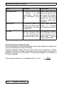
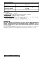
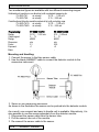
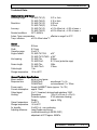
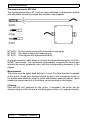
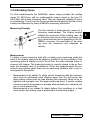
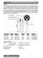
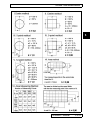
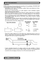
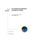
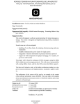
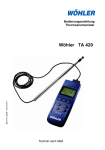
Selecting the Right Flow Sensor 3.5 Flow Sensors 3.5.1 Selecting the Right Flow Sensor For measurement of flow velocities the ALMEMO® sensor range provides thermoanemometer probes, pitot tubes and rotating vanes. The selection criteria are the measuring range and the operating temperature as follows: Sensor Flow Velocities Oper. Temperatures Thermoanemometer 0.1 to 50 m/s to 60°C Rotating vanes 0.2 to 40 m/s to 140°C Pitot tubes 7 to 100 m/s to 600°C 3 Measuring Range and Operating Temperature of Different Probes Thermoanemometer up to 60°C Rotating vanes up to 140°C Pilot tubes up to 600°C ALMEMO® Manual 3-5-1 Selecting the Right Flow Sensor Sensor: Advantages Disadvantages Thermoanemometer very small air flows can also be measured (e.g. draft measurements), non-directional measurement is possible sensitive sensor electronics, sensitive with regard to mechanical stress and contamination, sensitive with regard to turbulent flow, high current consumption, limited ambient temperature Rotating vanes high accuracy at medium flow sensitive sensor electronics, velocities and medium ambi- sensitive to mechanical ent temperatures, insensitive stress, depending on direction to turbulent flow Pitot tubes copes with high flow velocities and rough operating conditions, high operating temperatures possible, easy to clean highly depending on direction, low flow velocities cannot be measured, depending on temperature,limited accuracy, sensitive to turbulent flow Positioning The Air Velocity Probe The correct position of the sensing probe is the main condition for reliable and accurate measurement of the air velocity. Turbulence appears after fans as well as after turns, junctions or section changes in the duct. Reliable measurements are only possible if the probe is placed far enough from such places. The minimum distance is a function of the duct’s diameter. The equivalent diameter of a rectangular duct a x b is: 3-5-2 ALMEMO® Sensors D= 2ab a+b Selecting the Right Flow Sensor The following pictures are guidelines for correct installation of air velocity transmitters. Reliable measurements can be made by positioning the transmitter after filters (clean rooms), air heaters or air coolers, where the turbulence is very low. The probe shall be installed in the middle of the duct. Preferred location after filters, rectifiers, coolers (no turbulances) The probe shall be placed in front of diffusers or confusers. Filters and coolers calm down the air flow. ALMEMO® Manual 3-5-3 3 Thermoanemometer 3.5.2 Thermoanemometer Thermistors and hot-wire anemometers are highly sensitive sensors that can also measure very small air velocities. They are suitable for use in all fields of air conditioning, ventilating, indoor applications and measurements at working places (draft). The ALMEMO® sensor range provides thermoanemometer probes for different measuring ranges and measuring accuracies: • Thermoanemometer FV A645-THx with plug-on module housing and fixed measuring range. • Thermoenemometer MT 84x5 with separate housing for electronics, ALMEMO® connecting cable and selectable measuring range. The measuring variables, temperature (FVA935-TH) and air velocity are programmed within the ALMEMO® sensor connector on two measuring channels. They can be activated and displayed with the correct scaling and dimension by every ALMEMO® measuring instrument. For volume flow rate measurements the cross section or the diameter of the ventilating shaft can be easily entered into ALMEMO® hand-held devices. Measuring Principle A temperature-dependent semiconductor (NTC) is integrated in the measuring probe and is heated by a current. The heated semiconductor cools down as soon as it is exposed to an air flow. The amount of heat loss is a measure for the air velocity. A control circuit keeps the temperature of the element, which has cooled down by the air flow, on a constant value. The control current is proportional to the flow velocity. 3-5-4 ALMEMO® Sensors Thermoanemometer Thermoanemometer FVA935-THx The air velocity sensor is a hot film anemometer. An electrical current is increasing the temperature of a resistor on the substrate. The flowing air causes a reduction of this temperature. The cooling effect is directly proportional to the mass flow and consequently to the air velocity and inversely proportional to the air temperature. At equilibrium, the temperature of the sensor’s surface is the measure for mass flow. The integrated temperature sensor is used for the purposes of automatic temperature compensation. FVA935-TH4 / TH5 FVA935-TH4Kx / TH5Kx Technical data Flow FVA935TH4/TH4Kx FVA935TH5/TH5Kx Measuring range: 0 ... 2 m/s 0 ... 20 m/s Resolution: 0.001 m/s 0.01 m/s Response time: Accuracy < 1,5 s ±(0.04 m/s + 1% of meas. val.) ±(0.2 m/s + 2% of meas. val.) Temperature compensation: 0 ...+50 °C Direction facing the flow: bidirectional Angle dependence: <3% of meas. val. with deflection < 15° Temperature Measuring range: -20 ...+70°C Resolution: 0.1°C Accuracy: ±0.7 °C Nominal conditions ALMEMO® Manual 3-5-5 3 Thermoanemometer Temperature: 22 °C ± 2 K Atmospheric humidity: 45 ±10 % r.H. (non-condensing) Atmospheric pressure: 1013 mbar Power supply: 6 ... 13V / 40 mA Dimensions Probe diameter 6 mm FVA935TH4/TH5 Probe with handle, probe lengths : 210 mm (plus handle) ALMEMO® cable, 1.5 meters FVA935TH4Kx/TH5Kx Probe with remote electronics in the cable housing Probe lengths THxK1, 80 mm / THxK2, 300 mm Probe cable 5 m to electronics, ALMEMO® cable, 1.5 m Maintenance Due to the absence of moving parts, the E+E air velocity transmitters are very reliable. Their innovative hot film anemometer principle makes them highly insensitive to dust and dirt. Under normal environmental conditions no maintenance is required. For operation in polluted environment we recommend to clean the sensor periodically by washing it in isopropylalcohol and let it dry. Do not touch or rub. 3-5-6 ALMEMO® Sensors Thermoanemometer Thermoanemometer FV A605-TA For measuring the air velocity the ALMEMO® range of sensors includes rotating vanes, Pitot tubes and laser-calibrated thermoanemometers with unidirectional or omnidirectional measuring sensitivity. By storing the sensor data in the ALMEMO® connector, the measured values are indicated in m/s and with the correct scaling. It is also possible to measure the volume flow by entering a factor or the cross sectional area. Measuring Principle: The sensor contains a NTC resistance, which, with respect to the ambient temperature, is heated up to a constant overtemperature. The flow rate is determined by measuring the required heating power. As this measurement strongly depends on the ambient temperature a further precision NTC resistance is used to measure and automatically compensate the ambient temperature. Thermoanemometers are particularly suitable for low air velocities, e.g. draught measurements. Types: FVA605-TAx FVA605-TAxO The thermoanemometer consists of a sensor tube that contains the NTC temperature sensor, the heated miniature thermistor, and the sensor converter module including the detector electronics for the transducer. The thermoanemometer has been adjusted together with the sensor to be used with it. The converter module and the sensor can, therefore, not be interchanged! The module is marked with the same fabrication number as its sensor (see type plate). ALMEMO® Manual 3-5-7 3 Thermoanemometer Two mechanical types are available with two different measuring ranges: Unidirectional (sensitive in one direction) with a protected measuring tip: FV A605-TA1: air velocity 0.010 .... 1.000 m/s FV A605-TA5: air velocity 0.15 ... 5.00 m/s Omnidirectional (direction-sensitive spherical tip) with protecting cage FV A605-TA1O: air velocity 0.010 .... 1.000 m/s FV A605-TA5O: air velocity 0.15 ... 5.00 m/s Programming: Range: Output signal: Range: Dimension: Factor: Exponent: Base: FV A605 TA1/1O 0.010 .... 1.000 m/s 0 .... 1V d2600 m/s 0.1 +1 - FV A605 TA5/5O 0.15 ... 5.00 m/s 0 .... 1V d2600 m/s 0.05 +2 - Mounting and Handling: 1. Connect the sensor to the blue sensor cable. 2. Use the black ALMEMO® cable to connect the detector module to the measuring instrument. 3. Switch on the measuring instrument. As shown in the illustration the sensor can be pushed into the detector module. As a result, one compact and easy to handle unit is available. Alternatively, it is also possible to use the sensor separately from the detector module: 1. Disconnect the sensor cable from the sensor tube. 2. Pull the sensor tube out of the module. 3. Re-connect the sensor cable to the sensor. 3-5-8 ALMEMO® Sensors Thermoanemometer Fühlerschutz: FV A605 TAxO 1.When in meas. position, hold sensor tip at the knurled handle band (a). 2.Turn the blue sensor handle (b) clockwise. 3.The handle snaps back (c) and the sensor tip disappears in the protected position. 4.Follow the steps 3 to 1 in reverse to bring the sensor tip back into the measuring position. FV A605 TAx 1.To open the sensor tip push the black protecting cap (a) back in the direction of the handle. 2.With the sensor tube held in a fixedposition, it can be loosened or locked by slightly twisting the blue sensor handle (b). 3.Bring the sensor tube in the requiredposition and secure by twisting. Measurement: After connecting the probe and switching on the ALMEMO® device the measured values will be correctly scaled including their dimension and can be immediately read out in m/s. When performing measurements in an air duct the safety distances to turbulent points must be observed. To obtain undisturbed measured values the instrument ALMEMO® 2390-5 or 2690-8 is particularly suitable because it continuously averages the measured values by the function TIME CONSTANT. Further measuring functions for averaging and for volume flow measurements are described in the ALMEMO® Manual (chapt. 3.5.5) or Description on Averaging. ALMEMO® Manual 3-5-9 3 Thermoanemometer Zero Point Correction: Generally, a re-adjustment of the zero point is not required. However, during long term operation or when exposed to heavy shocks during transportation the zero point can slightly shift. If the output signal is not equalling 0m/s when the sensor is covered, a zero point correction should be performed. 1. The sensor must be closed. Wait at least 3min after closing. 2. For approximately 3 to 4 seconds short out pin 1 and pin 5 located at the socket "LEMO (large)" and then disconnect them again. 3. The detector module is now in the adjustment mode and automatically performs a zero point correction. After a waiting period of approximately 2 minutes the sensor is operational again. It must be ensured that the ambient temperature remains stable during the adjustment. Fuse: If no output signal is available despite the supply voltage being applied, the power supply must be interrupted for at least 30 seconds. This allows the (possibly) triggered PTC fuse to regenerate again. Cleaning: Generally, the sensors are maintenance-free. However, the sedimentation of contamination at the high temperature NTC can lead to errors of measurement. For cleaning purposes the head part can be thoroughly rinsed in a non-aggressive cleansing solution. Afterwards rinse in distilled water and allow to completely dry. 3-5-10 Attention! Do NOT touch the tip of the sensor! NEVER dry the head part using a hot-air blower or compressed air! The sensitive measuring cells could be damaged. ALMEMO® Sensors Thermoanemometer Technical Data: Electronics Box with Sensor Measuring range: FV A605 TA1(O): FV A605 TA5(O): Resolution: FV A605 TA1(O): FV A605 TA5(O): Accuracy: FV A605 TA1(O): FV A605 TA5(O): Nominal conditions: 22°C, 960hPa Autom. Temp.-compensation: Temp. influence: ±0.5% of final value/°C Sensor Head size: Shaft: Operative range: Angle of attack: Inlet opening: Sensor length: Cable length: Storage temperature: Ø 8 mm Ø 15 mm 0 to 40°C FV A605 TA1/TA5: FV A605 TA1O/TA5O: FV A605 TAx FV A605TAxO: FV A605 TAx: FV A605 TAxO: 1.5m -30 to +90°C 0.01 to 1m/s 0.15 to 5m/s 0.001m/s 0.01m/s ±1.0% of final val., ±1.5% of meas. v. ±0.5% of final val., ±1.5% of meas. v. effective in range 0 to 40°C 3 ±30° ±180° Ø 9mm Ø 110 mm (protective cage) 300m 310mm General Technical Specifications Meas. medium: dry air or inert gases Response time: FVA605TAxD: smoothened: 1t = 2s FVA605TAxU: not smoothened: 1t = 100ms Power supply: through ALMEMO® device (approx. 7 to 10V) Current consumption: approx. 70mA Output signal: 0 to 1V, linearised, minimum load resistance 10kW Housing: Dimensions: 100 x 60 x 35 mm (L x W x H) Protection system: IP 40 (aluminium housing) Weight: approx. 250g Operat. temperature: 0 to 40°C Storage temperature: -30 to 90°C Air humidity: 0 to 90% r.h., non-condensing Adjusting reference: Laser-Doppler wind tunnel, (certificate according to SN EN 45001) adjustment at 22°C/approx. 960hPa ALMEMO® Manual 3-5-11 Thermoanemometer Thermoanemometer MT 84x5 The thermoanemometers MT 84x5 are laser-calibrated, high-precision probes with adjustable measuring ranges and standard output signals. MT 8455: MT 8465: MT 8475: Multi-purpose sensor with protected measuring tip Rod sensor with small measuring tip Omni sensor with symmetrical ball tip A special connector cable allows to connect the thermoanemometers to all ALMEMO® instruments. The instruments automatically recognise the sensor and indicate the correct measured value, with the corresponding dimension, in the display. Measurement The probe must be tightly fixed before it is used. The flow direction is marked at the probe. A high time constant should be set or the averaging function of the instruments should be used to obtain undisturbed measured values, which enables an easier read-out of fluctuating values provided on the display. Cleaning Dust and dirt can sediment on the probe. If necessary, the probe can be cleaned using a soft brush and a mild detergent solution, e.g. isopropyl alcohol. 3-5-12 ALMEMO® Sensors Thermoanemometer Technical Data MT 84x5: Measuring ranges: Accuracy: Nominal temperature: Nominal position: Resolution: Reproducibility: Supply voltage: Current consumption: Time constant: Operating range: Dimensions: MT 8455, MT 8465 adjustable from 0.125 m/s to 1.0 / 1.25 / 1.5 / 2.0 / 2.5 / 3.0 / 4.0 / 5.0 / 7.5 / 10.0 12.5 / 15.0 / 20.0 / 25.0 / 30.0 / 40.0 / 50.0 m/s MT 8475 adjustable from 0.05 m/s to 0.5 / 0.75 / 1.0 / 1.25 / 1.5 / 2.0 / 2.5 m/s MT 8455/8465: ± 2% of meas. value, ±0.5% of selected range MT 8475: ± 3% of meas. value, ±1 % of selected range MT 8455/8465: 18–28°C<,> °C +0.2% per °C MT 8475: 20–26°C<,> °C +0.5% per °C horizontal 0.07 % of selected range <±1% of measured value 11 to 30 V DC maximum 350 mA selectable from 0.05 to 10 s 0 to 60 °C probe 300 mm long, meas. tip 32 mm, cable 5 m housing 126 x 80 mm, 60 mm high ALMEMO® Manual 3 3-5-13 Pressure Modules for Dynamic Pressure 3.5.3 Pressure Modules for Dynamic Pressure Basic Principles static pressure total pressure The air velocity is determined by the dynamic pressure and the static pressure, which develops when a Prandtl Pitot tube is placed in an air flow. The total pressure strikes the opening of the Pitot tube and is available at the terminal (+) of the pressure module. The pure static pressure is measured via side slots and is available at the terminal (-). The pressure difference, i.e. the dynamic pressure is a measure for the velocity in the flow. The dynamic pressure is calculated and indicated. The dynamic pressure relates to the air velocity as follows: 1. Density of the air: = 0 2. with ρ0 = T = 1.292 kg/m3 (density at 0°C) air temperature in °C Air velocity (valid up to approx. 40 m/s): p= dynamic pressure in Pa k= probe-related coefficient Prandtl tube: k=1 cylindrical probe: k = 1.7 Air velocity with consideration of the compressibility of the air (also valid at more than 40 m/s): v= 3. 273 273T v= 2p kp p 2 p /2 p /4 c with with c = speed of sound in air (331 + 0.6 x T m/s) The formulae show the influence of the air temperature to the density of the air and, consequently, to the result of the measurement of the dynamic pressure. Furthermore, the deviation of the atmospheric pressure pa from the normal pressure 1013mbar also has an effect on the result. The following factor can be used for correcting the velocity: K= 3-5-14 1013mbar Pa ALMEMO® Sensors K ≈ 1 + (1013 - pa) · 0.0005 (in 1st approximation) Pressure Modules for Dynamic Pressure Air velocity for selected dynamic pressures (Prandtl Pitot tube, T = 22 °C) Dynamic pressure [Pa] Dyn. pressure [mmWS] Air velocity [m/s] 1 0.1 1.29 2 0.2 1,83 3 0.3 2,24 4 0.41 2.59 5 0.51 2.89 10 1.02 4.09 20 2.04 5.78 30 3.06 7.08 40 4.08 8.18 50 5.1 9.14 100 10.2 12.93 Correction factors for consideration of temperature and air pressure: The true air velocity is depending on the air temperature and the barometric air pressure. Therefore, the measured value must be corrected according to the following table to obtain exact measurements of the air velocity. Air temperature - 30 °C - 20 °C - 10 °C 0 °C 10 °C 20 °C 30 °C 40 °C 50 °C 60 °C 70 °C 80 °C 90 °C 100 °C 150 °C 200 °C 250 °C 300 °C 400 °C 500 °C 600 °C 700 °C 940 mbar 0.942 0.961 0.98 0.998 1.016 1.035 1.051 1.069 1.085 1.102 1.118 1.135 1.151 1.167 1.242 1.314 1.381 1.446 1.567 1.68 1.784 1.884 960 mbar 0.932 0.951 0.97 0.988 1.005 1.024 1.04 1.057 1.074 1.09 1.106 1.123 1.139 1.154 1.229 1.3 1.367 1.431 1.55 1.663 1.766 1.865 980 mbar 0.922 0.941 0.96 0.978 0.995 1.013 1.029 1.047 1.063 1.079 1.095 1.111 1.127 1.142 1.216 1.287 1.353 1.416 1.534 1.646 1.748 1.846 1000 mbar 0.913 0.932 0.95 0.968 0.985 1.003 1.019 1.036 1.052 1.068 1.084 1.1 1.116 1.131 1.204 1.274 1.339 1.402 1.519 1.629 1.73 1.827 1020 mbar 0.904 0.923 0.941 0.958 0.975 0.993 1.009 1.026 1.042 1.057 1.073 1.089 1.105 1.12 1.192 1.261 1.326 1.388 1.504 1.613 1.713 1.809 ALMEMO® Manual 1040 mbar 0.895 0.914 0.931 0.949 0.966 0.983 0.999 1.016 1.031 1.047 1.063 1.078 1.094 1.109 1.18 1.249 1.313 1.375 1.489 1.597 1.696 1.791 3-5-15 3 Pressure Modules for Dynamic Pressure Example: Air velocity 50 m/s, air temperature 80 °C, atmospheric pressure 960 mbar. The measured value must be multiplied with the correction value 1.123. The air velocity is, therefore, 56.1 m/s. ALMEMO® Pressure Connector: For flow measurements the ALMEMO® sensor range provides plug-on pressure connector FDA602-SxK and, as accessories, robust stainless steel or nickel-plated brass Prandtl Pitot tubes. They are connected to the pressure connector via hoses. Cylindrical probes can be used if the specific probe coefficient (1.7) is considered by programming the factor 1/ 1,7 = 0.767. The measuring variables, dynamic pressure and air velocity are programmed within the ALMEMO® sensor connector on two measuring channels and can be activated and displayed with the correct scaling and dimension by every ALMEMO® measuring instrument. Pressure Connector FDA602-SxK Designation Channel FDA602-S1K: 1st chan: 2nd chan: FDA602-S6K: 1st chan: 2nd chan: 3-5-16 Meas. Range 0.5...40.0 m/s ± 1250.0 Pa 1.8...90.0 m/s ± 6800 Pa ALMEMO® Sensors Pitot tube FD9912 Dim ms Pa ms Pa Range L840 Volt L890 Volt Factor 0.4 Exp 3 4 Pressure Modules for Dynamic Pressure Zero Point Correction of the Pressure Sensors The zero point of the pressure sensors can shift due to positional changes and temperature variations. Therefore, it is useful to perform a zero point correction before each measurement. For the zero point correction, the pressure hoses or the Pitot tube must be removed from the flow conduit. When the measured value has stabilised, the zero point correction can be performed. This is described in the operating instructions supplied with each device under “zeropoint / sensor adjustment” For the necessary interface command please refer to Section 6.4.2. The zero point correction must be performed separately for each active channel (m/s, Pa). The zero point correction data is lost on switch off. Therefore, a new correction must be performed for the next measurement. Temperature Compensation If the measuring temperature largely deviates from the reference temperature of 25°C the temperature influence (range -50.0 to +700.0°C) should be compensated by performing a measurement preferably with a NiCr-Ni temperature sensor. With ALMEMO® V5 and V6 devices every suitable temperature sensor (resolution 0.1°C) can be used for compensation (see 6.3.4). By means of the reference channel, the air temperature can, at the measuring instrument ALMEMO® 2295-6, for compensation purposes, be entered for one flow measurement channel if the switch position COMPENSATION is selected. If the operating conditions are relatively constant it is sufficient to enter a correction factor according to the above table. Handling the Pressure Modules Ensure that the Pitot tube is properly connected. A confusion of the pressure connectors will cause incorrect measurements. Attention: The pressure sensors contain very sensitive pressure cells. Note the permissible maximum pressures - these must not be exceeded! Caution when removing the hoses! Do not squeeze the hoses. Harmful negative pressures can then be avoided. Avoid strong vibrations! Do not let aggressive gases penetrate the membrane or pressure cells, as they could be destroyed! ALMEMO® Manual 3-5-17 3 Pressure Modules for Dynamic Pressure Technical Data Pressure connector: Overload capacity: maximum triple measuring range Max. common mode pressure: 700 mbar Accuracy (zero-pt adjusted): ±0.5% of final value in range 0 to positive fin. val. Nominal temperature: 25°C Temperature drift: max. 1.5% (typ. 0.5%) of final value Compensated temp. range: 0 … +70°C Operating range: –10 to +60°C, 10 to 90% r.H. non-condensing Dimensions: 90 x 20 7.6 mm Hose connection: Ø 5mm, 12mm long Sensor material: aluminium, nylon, silicone, silica gel, brass Pitot tubes: Order No. FD 9912-33MS FD 9912-33VA FD 9912-54MS Head-Ø 3 mm 3 mm 5 mm Shaft-Ø 6 mm 6 mm 8 mm Length 300 mm 300 mm 400 mm FD 9912-54VA FD 9912-56MS FD 9912-56VA 5 mm 5 mm 5 mm 8 mm 8 mm 8 mm 400 mm 600 mm 600 mm 500 °C 350 °C 500 °C FD 9912-84MS FD 9912-84VA FD 9912-88MS 8 mm 8 mm 8 mm 8 mm 8 mm 8 mm 400 mm 400 mm 800 mm 350 °C 500 °C 350 °C FD 9912-88MS FD 9912-97VA FD 9912-97VA 8 mm 10 mm 10 mm 8 mm 10 mm 10 mm 800 mm 1000 mm 1000 mm 600 °C 350 °C 600 °C FD 9912-98MS FD 9912-98VA FD 9912-99MS 10 mm 10 mm 20 mm 20 mm 20 mm 20 mm 1500 mm 1500 mm 2000 mm 350 °C 600 °C 350 °C FD 9912-99VA 20 mm 20 mm 2000 mm 600 °C MS = brass nickel-plated, VA = chrome-nickel steel 3-5-18 ALMEMO® Sensors Oper. up to 150 °C 300 °C 350 °C Rotating Vanes 3.5.4 Rotating Vanes For flow measurements the ALMEMO® sensor range provides the rotating vanes FV A915-Sxxx with an exchangeable snap-on head or the type FV A915-MA1 with a fixed measuring head. They are especially suitable for use in air conditioning. The air velocity can be activated and displayed with the correct scaling and dimension by every ALMEMO® measuring instrument. Measuring Principle The flow velocity is determined by means of a frequency measurement. The flowing medium initiates the movement of the rotating vane. By an inductive pulse count, which is performed using a microcontroller and is integrated in the ALMEMO® connector, the revolutions of the rotating vane are measured and displayed as velocity. Measurement To obtain correct measuring data with a rotating vane measuring probe the shaft of the rotating vane must be aligned in parallel to the flow direction. If the measuring probe is slightly moved in the air flow, the value indicated at the instrument will change. The measuring probe is correctly placed in the air flow, when the indicated value is at maximum. When flow measurements are performed using rotating vanes there can be measuring situations with a very inhomogeneous flow profile: - - Measurement at air outlets:To obtain correct measuring data the measurement must be performed some distance away from the grill-screen and large rotating vanes must be used allowing the measured values to be integrated and averaged over the larger measuring head. If smaller rotating vanes are used it is necessary to average either spatially over individual values or over a specific time. Measurements at air intakes:To obtain defined flow conditions in a fixed cross section the rotating vane is positioned in a measuring hopper. ALMEMO® Manual 3-5-19 3 Rotating Vanes Design Our rotating vanes are sensitive transducers with diamond bearings that are very precisely adjusted. This ensures high accuracy. The aluminium rotating vanes have stream-lined measuring heads made from plastic material (polysulfone). The shafts are, as standard, guided in protected, oiled berylliumbrass bearing sleeves and supported in tips made from special casehardened steel. This makes the transducers especially suitable for use in air conditioning. The rotating vanes are partly equipped with snap-on measuring heads and are, therefore, very easy to maintain. Meas. Range 0.3 to 20 m/s 0.4 to 40 m/s 0.5 to 20 m/s 0.6 to 40 m/s 0.2 to 20 m/s Head Ø 22 mm 22 mm 11 mm 11 mm 80 mm Opening from 35 mm from 35 mm from 15 mm from 15 mm from 108 mm Technical Data: Accuracy: FV A915 S120-S140: FV A915 S220-S240: FV A915 SMA1: Max. resolution: Nominal temperature: Operating range: 3-5-20 ALMEMO® Sensors Shaft Ø 15 mm 15 mm 15 mm 15 mm 15 mm Length 175 mm 175 mm 165 mm 165 mm 235 mm ±0.5% of f.sc.v. ±1.5% of m.v. ±1 % of f.sc.v. ±3 % of m.v. ±0.5% of f.sc.v. ±1.5% of m.v. 0.01 m/s 22°C ±2K –20 to +140°C Order No. FV A915 S120 FV A915 S140 FV A915 S220 FV A915 S240 FV A915 SMA1 Volume Flow Measurement 3.5.5 Volume Flow Measurement For determining the volume flow V in ventilating channels the medium flow velocity is multiplied with the cross section area F: V = vM F 0.36 V = volume flow in m3/h, F = cross section in cm2, vM = medium flow velocity in m/s Air Volume Measurement with Mountable Hopper For air volume measurement at air vents (e.g. disk valve) up to 200mm diameter the mountable hopper ZV 9915-LM is available for the macro rotating vane FV A915-MA1 as an accessory. By scaling the air velocity with the factor 1.3762, exponent +1 and dimension mh the air volume is obtained in m3/h. A correction factor for the forced circulation of the rotating vane is already considered. The measuring variable volume flow can also be programmed as 2nd channel. Chan. 1st ch.: 2nd ch.: Function air velocity volume flow Meas. Range 0.2...20.00 m/s 1.0...275.0 m3/h Dim ms mh Range L420 L420 Factor 1,376 Exp +1 Volume Flow Measurement with Center Probe For a rough measurement of the volume flow it is sufficient to place a flow probe in the center of the flow channel. The medium flow velocity is approximately 0.8 v (see below 'net measurement center method'). By scaling the velocity with the factor (0.8 F 0.36) the momentary volume flow can be continuously indicated in m3/h. It may be also necessary to program the exponent and the dimension. Determining a Volume Flow from Average Value & Cross Section To obtain measured values as accurately as possible, the flow velocity must be integrated and averaged over the whole area. The hand-held devices 2390-5, 2690-8, 2890-9 and system 5690-2 allow for entering the cross section area directly via keyboard in function QF, as area F with 32000cm2 at maximum, or in the function DN via the diameter with 2000mm at maximum. The volume flow V can then be read out in function channel “Flow” directly in m3/h - the product of average value and surface; (see device instructions, “Volume flow measurement”). It is also possible, by means of function channels “Flow” and “n(t)”, to output and to save the volume flow and the number of measuring operations; (see Section 6.3.3). ALMEMO® Manual 3-5-21 3 Volume Flow Measurement Determination of the Average Flow Velocity The most important parameter for the measurement of the volume flow is the average flow velocity vM. As the velocity has the highest value in the center of a channel and because it is significantly smaller at the walls, it is necessary to use one of the following methods for averaging it over the cross section. Time-based Averaging: With air volume measurements at grill-screens the mean flow velocity can be determined by a time-based averaging: 1. Set the averaging mode for the time-based averaging 2. Place the rotating vane properly at one end and start averaging. 3. Proceed uniformly over the whole cross section. 4. When the other end has been reached, stop the averaging. Area Measurements: If flow measurements are performed for acceptance tests, according to the guidelines VDI/VDE 2640, the medium flow velocity is determined in a net of individual measuring points within the measuring cross section, which is placed vertically with respect to the flow direction. The averaging over single measurements should be used for these net measurements (see device manual). An overview of the different methods can be found on the following page. Precise measuring results can be obtained with a Pitot tube or a micro anemometer, which has a minimal influence on the flow. Depending on the measuring method the average value of the single measurements vM must be corrected by the correction factor k: v = k vM 3-5-22 ALMEMO® Sensors Volume Flow Measurement 3 ALMEMO® Manual 3-5-23 Volume Flow Measurement Procedure: If the measurements are performed according to the guidelines VDI/VDE 2640 the following notes must be observed: - Depending on the type of ventilation system there can already be turbulences at low flow velocities. - Perform the measurements in a quiet section of the ventilation system where turbulences are minimal. - Select the measuring point so that maximum safety distances are available before and after the measuring point. The safety distance N is the distance from a turbulence point to the measuring point. Turbulences can develop, for example, at fans, pipe bends, reductions, control flaps, rectifiers, heating units and filters etc. - The following formulae can be used to calculate the safety distances N for selecting the measuring point. L represents the free straight leg of a ventilating channel that is free from obstructions. - Select the safety distance N1=L1/D before the measuring point so that it is equal or larger than 6 and select the safety distance N2=L2/D after the measuring point so that it is equal or larger than 2. - If short, straight elements of a piping system are only available, a shorter safety distance N can be chosen when a larger number of measuring points is used for the averaging. However, N1=L1/D must at least total 2.5. 3-5-24 ALMEMO® Sensors