1
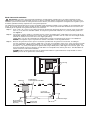
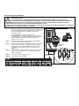
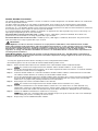
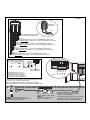
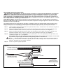
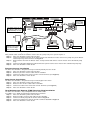
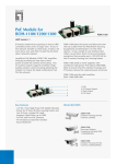
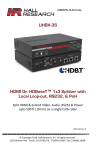
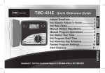
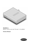
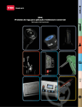
GDC 200 Stand-Alone Model
Installation Instructions
Specifications:
• Controls up to 200 stations for the
Stand-Alone model
• Input power supply
100 VAC, 50/60Hz
120 VAC, 50/60Hz
240 VAC, 50/60Hz
• GDC output voltage: 40 VAC max.
• GDC output power: 98VA max.
• Storage temperature: -30C–60C
• Operating temperature: 0–60C
• Cabinet Type: Non-corrosive, lockable wall mount,
indoor/outdoor installation
• Six 25.4mm conduit openings and one 38mm conduit opening
Cabinet Installation
Selecting the proper installation site for the GDC is essential to safe
and reliable operation. The GDC features a weather resistant cabinet designed for indoor or outdoor installation.
The GDC should be installed on a vertical wall or other sturdy structure near
a grounded power source. Select a location that shades the controller during the
hottest hours of the day and provides as much protection from direct sunlight,
rain, wind and snow as possible. DO NOT mount the controller where it is
exposed to direct spray from the irrigation system.
For easy operation and better view of the display, install the GDC so that the
display is at or slightly below eye level.
Step 1 – Drill two pilot holes 15.25cm apart for the top keyholes of the
controller cabinet.
Step 2 – Install the top screws leaving approximately 5–6mm of exposed
screw to accommodate
the cabinet.
If mounting the cabinet on dry wall or
masonry, install the appropriate type of screw
anchors or fasteners to ensure secure installation.
15.25cm
23.175cm
Step 3 – Hang the cabinet using the top keyhole slots.
See Figure 1.
Step 4 – Open the cabinet door and install the bottom two
screws to
secure the cabinet.
Figure 1
Earth Ground Installation
IMPORTANT! The GDC surge protection components cannot properly function unless an efficient pathway to earth
ground is provided. The ground path must be as direct as possible, without sharp bends and must not exceed 30 Ohm
resistance (when measured with an earth ground resistance device). All electrical components throughout the irrigation system
should be grounded similarly to provide the same ground potential.
The following instructions depict one of several acceptable earth grounding methods. Due to variables in soil composition and
terrain, the method shown may not be suitable for your installation site. Contact your local Toro distributor for assistance and
availability of the required earth ground resistance test instrument.
Step 1 – Drive a 5/8" x 8' (17mm x 2.5m) copper-clad steel rod into well moistened soil not less than 8' (2.5m) or not more
than 12' (3.7m) from the controller cabinet. The top of the ground rod should be 12" (30.5cm) below grade level.
See Figure 2.
Step 2 – Using a 5/8" (17mm) clamp or “Cad weld” fastener, attach an 8 AWG (8mm2) solid copper wire near the top of the
o
ground rod. Avoiding wire bends of less than 8" (20.3cm) radius and more than 90 , route the wire through conduit
and into the cabinet. Secure the wire to the copper ground lug.
Make sure the soil surrounding the ground rod(s) remains well moistened at all times. The addition of
some form of irrigation may be required if the cabinet is installed in a non-irrigated location.
Step 3 – Measure the ground resistance per the instructions provided with the ground test instrument. A reading of
0.0 Ohm is optimum, up to 10 Ohm is good and 11–30 Ohm is acceptable in most cases. If the resistance exceeds
the acceptable limit, additional ground rod(s) can be installed at a distance equal to twice the buried depth of the
first rod; i.e., 16' (4.9m). Interconnect the ground rods using 8 AWG (8mm2) solid copper wire and test again. If the
measured ground resistance continues to read above the acceptable limit, contact your local Toro distributor for
further assistance and recommendations.
Installing a round valve box over the ground rod enables the ground rod to be easily located as well as
providing access to the ground wire connection(s).
Figure 2
Ground Lug
Valve Box
8 AWG (8mm2)
Solid Copper Ground Wire
12" (30.5cm)
8" (20.3cm)
Minimum Radius
8'–12'
(2.4m – 3.7m)
Ground Wire To
Additional Rod(s)
(Optional)
Copper Clad
Ground Rod
90o Minimum Angle
Power Source Installation
WARNING! AC POWER WIRING MUST BE INSTALLED AND CONNECTED BY QUALIFIED
PERSONNEL ONLY.
ALL ELECTRICAL COMPONENTS AND INSTALLATION PROCEDURES MUST COMPLY WITH ALL
APPLICABLE LOCAL AND NATIONAL ELECTRICAL CODES. SOME CODES MAY REQUIRE A MEANS OF
DISCONNECTION FROM THE AC POWER SOURCE, INSTALLED IN THE FIXED WIRING, HAVING A CONTACT
SEPARATION OF AT LEAST 3mm IN THE LINE AND NEUTRAL POLES.
ENSURE THE AC POWER SOURCE IS OFF PRIOR TO SERVICING. FAILURE TO COMPLY MAY RESULT IN SERIOUS
INJURY DUE TO ELECTRICAL SHOCK HAZARD.
Step 1 – Turn off the power at the power source location and
place the controller’s power switch to OFF. Connect and
route the appropriate size 3-conductor cable (10 AWG
[2.5mm2] maximum) from the power source to the
controller cabinet.
Figure 3
The provided power cable access hole can
accommodate a 1" (25mm) conduit fitting. If conduit is
required, install a section of flexible 1" (25mm) electrical
conduit from the power source conduit box to the
cabinet’s access hole.
Step 2 – Open the cabinet door and remove the two retaining
screws from the power supply cover.
Step 3 – Locate the voltage cable assembly and note the voltage
on the label. The GDC is equipped with 120V cable
assembly from the factory. Replace the voltage cable
assembly with the proper rating as necessary. See
Figure 3.
Voltage Cable
Assembly
Step 4 – Strip the power cables and secure them to the terminal
block. Reference Table 1 for the appropriate type of
power connection.
Step 5 – Reinstall the power supply cover.
Step 6 – Apply power to the controller.
Flexible Conduit
(Optional)
Equipment
Ground
Line
Neutral
Station Decoder Installation
The station decoder module is available in 1-station, 2-station or 4-station configuration. The decoder modules are installed into
the GDC output board terminals.
The GDC model can handle up to 100 stations per output board. These stations can be connected to the output board
terminals in any configuration (25 stations connected to each of the four terminal pairs or 100 stations connected to one
terminal pair, etc.). The decoder modules can be connected in parallel anywhere on the two-wire communication line connected
to the station terminals. Each station can activate up to two solenoids.
It is recommended that the decoder modules are installed in an approved valve box to provide easy access to the wiring. Use
high-voltage waterproofing to all the wire connections.
Recommended Controller-to-Decoder cable: 14 AWG (2.5mm2), solid copper, jacketed 2-conductor, direct burial. The
preferred wire make and model is the Paige Irrigation Wire, Spec P7350D.
Recommended Decoder-to-Solenoid cable: 14 AWG (2.5mm2), solid copper, 2-conductor, direct burial. The preferred wire
make and model is the Paige Irrigation Wire, Spec P7351D.
IMPORTANT!
Cable Splices: In order for the wire connections to comply with the 2005 edition of the National Electric Code®
Article 300.5 (Underground Installations) and 110.14 (Electrical Connections), in wet or damp locations, the connector
must be listed under specification “UL 486D” if installed in a valve box. It must be listed under specification “UL 486DDirect Burial” if buried in dirt. This requirement applies to all electrical connections in wet or damp locations,
regardless of voltage. The 3M DBY-6 and DBR-6 are listed as “UL 486D-Direct Burial” and meet these requirements for
all underground installations.
Cable Burial Depth: The GDC decoder operate at voltages between 30–40 volts. The 2005 edition of the National
Electrical Code®, Article 300-5, requires that wires and cables subjected to voltages higher than 30 volts are to have a
minimum cover of 24" (60.96 cm).
• Use only wire approved for direct burial if installing the wires underground without conduit.
• All field wiring splices must be accessible to facilitate troubleshooting and/or service.
Step 1 – Route communication cable from the controller to the station decoder module installation location.
The maximum wire length between the controller and the decoder module is 15,000' (4500m).
Step 2 – Secure the communication wires to terminal 1 of the GDC output board. White wire onto the 1st terminal and black
wire onto the second terminal. See Figure 4.
Step 3 – Install the decoder module in a valve box. Record the decoder module’s address number found on the side label.
This address number identifies the station(s) that the decoder module control.
Step 4 – Secure the communication wires to the decoder module’s black and white wires. Connect the black communication
wire to the black decoder module wire. Connect the remaining communication wire (white) to the white decoder
module wire. Use proper water proofing method for all wire connections.
Step 5 – Route output wires from the decoder module to the solenoid.
The maximum wire length between the decoder module and the solenoid is 410' (125m).
Step 6 – Connect the solenoid wires to the decoder module’s station wires. The station wires are color coded for easy
identification. Connect the solid colored (red, green, orange or blue) station wire to the red/white solenoid wire.
Connect the similar color station wire with black stripe to the black solenoid wire. Waterproof all wire connections.
Step 7 – Connect an additional solenoid to the station wire as necessary.
Each station has a maximum load of two solenoids for pressure up to 150 PSI or 10 bar. One solenoid per
station loading for pressure exceeding 150 PSI or 10 bar.
Step 8 – Repeat Steps 3–8 for additional decoder modules.
Figure 4
DC Latching
Solenoid
Red
Black
White Power/Communication Wire
Black Power/Communication Wire
Station 1
Solid Red Station Wire - Connect to the Red/White solenoid wire
Red with Black Stripe Station Wire - Connect to the Black solenoid wire
Station 2
Solid Green Station Wire - Connect to the Red/White solenoid wire
Green with Black Stripe Station Wire - Connect to the Black solenoid wire
Station 3
Solid Orange Station Wire - Connect to the Red/White solenoid wire
Orange with Black Stripe Station Wire - Connect to the Black solenoid wire
Station 4
Solid Blue Station Wire - Connect to the Red/White solenoid wire
Blue with Black Stripe Station Wire - Connect to the Black solenoid wire
Each station can activate up
to two DC Latching Solenoids.
1-Station
Decoder
Module
Output Board
Station Wires
White
Black
White
Black
White
Black
White
Black
Out to additional
decoder modules
The GDC output board can
accommodate up to 100 stations.
The decoder modules can be
connected in any configuration
using the four station terminals.
Paths – 1
2
3
4
The maximum communication wire length between the decoder
module and the solenoid is 410ft (125m).
Recommended Cable for Decoder-to-Solenoid is the Paige®
P7351D, 14 AWG, Solid Copper, 2-Conductor, Direct Burial cable.
Valve Box
To easily identify stations for
troubleshooting, install wires with the same
color code as the station wires.
When possible, install
the decoder module in a valve
box for ease of service.
Maximum communication wire length
between the controller and the farthest
decoder is 15,000ft (4500m).
Recommended Cable for Controller-to-Decoder
is the Paige® P7350D, 14 AWG, Solid Copper,
Jacketed 2-Conductor, Direct Burial cable.
Grounding Communication Cable
IMPORTANT! Cable Splices: In order for the wire connections to comply with the 2005 edition of the National
Electric Code® Article 300.5 (Underground Installations) and 110.14 (Electrical Connections), in wet or damp
locations, the connector must be listed under specification “UL 486D” if installed in a valve box. It must be listed
under specification “UL 486D-Direct Burial” if buried in dirt. This requirement applies to all electrical connections in
wet or damp locations, regardless of voltage. The 3M DBY-6 and DBR-6 are listed as “UL 486D-Direct Burial” and meet
these requirements for all underground installations.
Cable Burial Depth: The GDC decoder operate at voltages between 30–40 volts. The 2005 edition of the National
Electrical Code®, Article 300-5, requires that wires and cables subjected to voltages higher than 30 volts are to have a
minimum cover of 24" (60.96 cm).
The optional lightning arrester (Toro P/N DEC-SG-LINE) is available to protect the decoder module in lightning prone areas.
Without lightning arrester, the decoder are vulnerable to lightning damage. In order for these arrester to discharge lightning
energy efficiently, they must be properly grounded. Figure 5 illustrates the proper grounding and wiring of the arrester.
Step 1 – Locate decoder’s power/communication wires (black and white wires). Disconnect the wire connectors that joins it
to the controller-to-decoder cable.
Step 2 – Strip the insulation from lightning arrester’s white wire and connect it to the white wires from the decoder and
controller-to-decoder cable. Secure the splices with a water proofed wire connector. (See Figure 5.)
Step 3 – Strip the insulation from lightning arrester’s black wire and connect it to the black wires from the decoder and
controller-to-decoder cable. Secure the splices with a water proofed wire connector. (See Figure 5.)
Step 4 – Connect the lightning arrester’s ground wire to the ground plate’s wire. If the ground plate is not pre-wired, use a
10 AWG bare copper wire. (See Figure 5.)
IMPORTANT! Verify that the wire length between the lightning arrester and the ground plate is no less than
3' (91.44 cm). Longer lengths will decrease the lightning arrester’s effectiveness.
Step 5 –
Bury the Ground plate next to the valve box or decoder’s location. Set it at the maximum depth that
the ground wire would allow. Surround the ground plate with 50 lbs (2.68 Kg) of Earth contact material such as
PowerSet® (Paige Electric, part number 1820058).
Step 6 – Check the system for proper operation.
Figure 5
Toro Decoder Module
Use Paige P7351D for
Decoder-to-Solenoid
Communication Wiring
Lightning Arrester
Toro P/N DEC-SG-LINE
Paige P7350D
Controller-to-Decoder
Communication Cable
4'' x 36'' (10.16 cm x 91.44 cm)
Ground Plate - Surrounded by
50 lbs (2.68 Kg) of PowerSet®
3' (91.4 cm)
Minimum Distance
Between the Arrester
and the Ground Plate
Figure 6
Pressure Sensor
Terminals
Rain Sensor
Terminals
Toro
Maintenance
Remote (TMR)
Receiver Plug
Master Valve / Pump Relay
Switch Terminals
The 28VAC (Label A) can
also be used to power the
Toro Wireless Rain Sensor
(TWRS/TWRFS) receiver.
A
A
24-Volts Transformer
(Voltage Source must
not exceed 3 Amps
Max, 28 Volts Max)
Master valve
or
Pump Relay
Pressure Sensor
Rain Sensor
Master Valve / Pump Relay Installation
GDC provide switch terminals to control a master valve or a pump relay if the system requires it.
Step 1 – Place the controller’s power switch to OFF.
Step 2 – Connect the Positive/Hot wire of the power source that controls the master valve or the pump relay to the Master
valve/Pump relay switch terminal. See Figure 6.
Step 3 – Route another wire from the Master Valve / Pump terminal and connect it to the master valve solenoid or pump
relay.
Step 4 – Connect the Negative/Equipment ground wire of the power source to the master valve solenoid or pump relay.
Step 5 – Place the controller’s switch to ON.
Pressure Sensor Installation
The GDC 200 controller is designed to accept a normally-closed pressure sensor.
Step 1 – Place the controller’s power switch to OFF.
Step 2 – Route the pressure sensor’s cable into the controller.
Step 3 – Connect the cable wires to the Pressure Sensor Terminals (See Figure 6).
Step 4 – Place the controller’s switch to ON.
Rain Sensor Installation
The GDC 200 controller is designed to accept a normally-open rain switch.
Step 1 – Place the controller’s power switch to OFF.
Step 2 – Route the rain sensor’s cable into the controller.
Step 3 – Connect the cable wires to the Rain Sensor Terminals (See Figure 6).
Step 4 – Place the controller’s switch to ON.
Toro Maintenance Remote (TMR) Receiver Plug Installation
The GDC 200 controller is fully ccompatible with the TMR remote.
See TMR’s User’s Guide for operating and mounting instructions.
Step 1 – Place the controller’s power switch to OFF.
Step 2 – Route the TMR’s receiver plug cable into the controller.
Step 3 – Connect the RJ45 plug into the socket shown in Figure 6.
Step 4 – Connect the power wires into the 28 VAC terminals labeled A in Figure 6.
Step 5 – Place the controller’s switch to ON.
Lithium Battery Replacement
A 3.9V Lithium battery (P/N 363-2200) is installed in the timing mechanism to sustain the controller’s clock time and date for
approximately 10-years with no additional power applied.
WARNING! DANGER OF EXPLOSION IF BATTERY IS INSTALLED INCORRECTLY. REPLACE ONLY WITH THE
SAME OR EQUIVALENT TYPE OF BATTERY. ALWAYS DISPOSE OF USED BATTERIES ACCORDING TO THE
MANUFACTURER’S INSTRUCTIONS.
Step 1 – Place the controller’s power switch to OFF.
Step 2 – Remove the ribbon cable from the rear of the timing mechanism.
Step 3 – Remove timing mechanism’s circuit board by pushing the retaining clip downward while carefully pulling the PCB
board. See Figure 6.
Step 4 – Secure the Lithium battery into the battery socket. See Figure 7.
Step 5 – Reattach the circuit board to the timing mechanism.
Step 6 – Secure the ribbon cable back to the timing mechanism socket.
Step 8 – Place the controller’s switch to ON.
Figure 6
Figure 7
Push Retaining Clip
to Release the PCB
Disconnect the
Ribbon Cable
Electromagnetic Compatibility
Domestic: This equipment has been tested and found to comply with the limits for a FCC Class A digital device, pursuant to
part 15 of the FCC Rules. These limits are designed to provide reasonable protection against harmful interference when the
equipment is operated in a commercial environment. The equipment generates, uses, and can radiate radio frequency energy
and, if not installed and used in accordance with the instruction manual, may cause harmful interference to the radio
communications. Operation in a residential area is likely to cause harmful interference in which case the user will be required to
correct the interference at his own expense.
International: This is a CISPR 22 Class A product. In a domestic environment, this product may cause radio interference, in
which case the user may be required to take adequate measures.Each stations can activate up to two solenoids.
© 2009 The Toro Company, Irrigation Division • An ISO-9000-Certified Facility
Form Number 373-0446 Rev. B