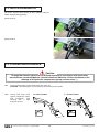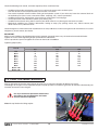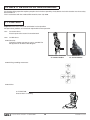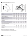
1
LOADER
MX C1
MX C2
MX 20Cu
MX 25Cu
MX 20C+
MX 25C+
MX 30C+
User manual
Please read carefully before using MX
loader
UK 362942 AE - 0711
Original instructions
Dear users,
Thanks you for confidence in our product. We are sure it will give you full satisfaction.
By taking a few minutes to read this manual, you will be able to obtain the best results from your MX loader, extend
its lifespan and work in complete safety.
The loader user manual is a very important document, please keep it with you in order to be able to use it if
required. Leave it available to any other user and give it to the next owner of this loader.
Pictures and technical information included in this document may not correspond precisely to your loader; but the
working conditions will be the same.
CONTENTS
Page
1. SAFETY REGULATIONS
6
2. SAFETY STICKERS
7
3. IDENTIFICATION PLATE 7
4. COUNTERWEIGHT
8
5. LOADER UNHITCHING
9
6. LOADER HITCHING
11
7. IMPLEMENT UNHITCHING - C+ LOADERS
13
8. IMPLEMENT HITCHING - C+ LOADERS
14
9. IMPLEMENT UNHITCHING / HITCHING - Cu, C1 and C2 LOADERS
16
10. IMPLEMENT LEVEL INDICATOR - C+ LOADERS
16
11. 3rd FUNCTION
17
12. MACH 2
17
13. SHOCK ELIMINATOR
18
14. LOADER MAINTENANCE
18
15. TRACTOR MAINTENANCE
19
16. SAFETY DEVICE ON LIFTING/CROWDING
20
17. CONTROL
20
18. GENERAL INFORMATION 21
19. TECHNICAL SPECIFICATIONS
22
DECLARATION OF CONFORMITY
23
The loader is a complex machine. The end user must read this
instruction book before first use.
Familiarise yourself with:
— Safety instructions.
— Hitching and unhitching of the loader.
— Hitching and unhitching of the implements.
— Full use of the controls.
• 19, rue de Rennes • BP 83221 • F - 35690 ACIGNÉ
5
Modification reserved
1. SAFETY INSTRUCTIONS
— Control the loader only from the driver’s seat. Do not let go of the controls until the movements are complete.
— Do not leave the seat before locking the controls to prevent any movement.
— Never leave the tractor while its loader is lifted. Following loader use, park the tractor with the loader lowered to the ground.
— It is compulsory to ensure that nobody is in the area while the loader is in use.
— The operation must use the implement designed and recommended by MX for the work to be carried out.
— The transport or elevation of persons using the loader is forbidden.
— Ensure tractor stability by using a counterweight. Please check the information regarding the counterweight in this user
manual.
— Restrict all movements while the load is lifted as the tractor may become unbalanced.
— The maximum front axle safe load provided by the tractor’s manufacturer must not be exceeded.
— The maximum front tyres safe load provided by the tyres’s manufacturer must not be exceeded.
— Check regularly tyres pressure.
— Regularly check the presence of safety pins and bolts. Do not replace with any other object such as nails, wire, etc.
— Hitch the loader only to a tractor fitted with a roll-over protective structure (ROPS) or a falling object protective structure
(FOPS). This should be in the protective position when using the loader.
— Watch out for overhead electrical and telephone cables when manoeuvring with the loader in the raised position.
— In compliance with the standard EN 12525, the controls for operating the loader and implements must be of the «sustained
action» type with the exception of the lift floating position which can be maintained in its position by a notching system.
— Any activity relating to defect investigation ( diagnosis ) and / or disassembly of parts may only be undertaken by an
accredited professional who shall assure his safety and the protection of the environment in which the actvity is conducted,
in particular in the event of an activity involving the loader staying in the lifted position.
CAUTION !
— The loader’s hydraulic circuit is designed to have a maximum service pressure of 200 bar.
— Never modify hose connections.
— The breaking of the seals will result in the cancellation of the MX responsibility for all the equipment supplied.
— The assembly of an MX loader which excludes the recommendations in the MX price list in force at the purchase date,
cancels the MX guarantee on all the equipment supplied.
— Any modification to a section of any MX equipment (implements, loader, bracket, etc.) or the use of an implement or element
installed on the MX loader of foreign origin, cancels the MX guarantee for all equipment supplied.
— Use only MX original spare parts. Do not modify your MX loader or its accessories yourself or have another person modify
them (mechanical, electrical, hydraulic, pneumatic characteristics), without prior written agreement from MX. Failure to
respect these regulations may make the loader dangerous. MX will disclaim all responsibility in the event of damage or
injury.
— The guarantee is immediately invalid when the instructions for use, and the MX loader maintenance schedule outlined in
"User Manual" are not observed.
• 19, rue de Rennes • BP 83221 • F - 35690 ACIGNÉ
6
Modification reserved
2. SAFETY STICKERS
Security stickers are located on the loader. Keep them readable and clean, and change them if damaged.
C1 and C2 loaders
C+ and Cu loaders
3. IDENTIFICATION PLATE
The identification plate is located inside the LH arm, next to
the implement level indicator.
19, rue de Rennes F - 35690 ACIGNÉ
Désignation/
Designation
Type / Model / Typ
N˚ de série
Serial number
Seriennummer
Poids à vide
Unloaded weight / Leergewicht
• 19, rue de Rennes • BP 83221 • F - 35690 ACIGNÉ
7
Année / Year
kg
328462
The serial number and loader type which are indicated on
this plate might be requested when requiring spare parts or
technical assistance.
Modification reserved
4. COUNTERWEIGHT
The stability of the tractor and loader can only be ensured with a counterweight on the rear of the tractor.This counterweight
must ensure that a minimun of 20 % of the total weight (Tractor, loader, implement, maximum load and counterweight)
is applied on the back axle of the tractor in order to work in a safe condition.
Below is the calculation method which indicates the required counterweight (M)
M>
5 N b + I2 (P + N - 5 G)
5 (I1 + I2) - I2
G : Weight on the rear axle, wihtout counterweight, with an empty implement (kg).
G1: Weight on the front axle, without counterweight, with an empty implement (kg).
b : Distance from the front axle to the implement centre of gravity (mm).
I1 : Distance from rear linkage pins to the rear axle (mm).
I2 : Wheelbase.
N : Loader payload at 2 m (Kg).
P : G + G1 (kg)
M : Weight of the counterweight (kg).
• 19, rue de Rennes • BP 83221 • F - 35690 ACIGNÉ
8
Modification reserved
5. LOADER UNHITCHING
Caution
This operation must be carried out by the driver who must leave the seat and
ensure all manoeuvres are forbidden while he is working on the loader.
The loader must always be coupled to an implement to unhitch it.
5.1
Choose a flat and stable area.
5.2
Put the implement dumped on the ground slightly (20°
approx.).
5.3
Fit the parking stand(s).
C1 and C2 loaders
5.4
C+ and Cu loaders
Remove the frame locking pins and insert them into the
dedicated holes.
• 19, rue de Rennes • BP 83221 • F - 35690 ACIGNÉ
9
Modification reserved
5.5
Lower the loader using the DA, to retract the lift rams.
Crowd slightly to position the parking stands.
5.6
Crowd the implement slightly, driving forward to release
the loader towers away from the bracket.
Pull the parking brake. Turn off the engine..
5.7
Completely decompress all the hydraulic circuits.
5.8
Close the tap and disconnect the hydraulic couplings.
• 19, rue de Rennes • BP 83221 • F - 35690 ACIGNÉ
10
Modification reserved
5.9
Position the protective covers (clean) to the male and
female couplings.
Store the hoses on the loader.
5.10 Reverse the tractor a little, to clear the loader from the
bracket.
6. LOADER HITCHING
6.1
Drive slowly forward so that the bracket is some 5cm away
from the loader towers.
Pull the parking brake. Turn off the engine.
• 19, rue de Rennes • BP 83221 • F - 35690 ACIGNÉ
11
Modification reserved
6.2
Completely decompress all the hydraulic circuits.
6.3
Connect the hydraulic couplers, matching the colour
codes.
6.4
Open the tap.
6.5
Tip the implement so as to lift the front of the loader: by
rotating it, the frames must fit into the bracket yokes.
• 19, rue de Rennes • BP 83221 • F - 35690 ACIGNÉ
12
Modification reserved
6.6
Raise the implement horizontally to 0.30 m from the
ground.
0.3 m
6.7
Lock the loader frame on the bracket with the pins and split
pins.
Fold the parking stands away.
7. IMPLEMENT UNHITCHING - C+ LOADERS
Caution
This operation must be carried out by the driver who must leave the seat and
ensure all manoeuvres are forbidden while he is working on the loader.
7.1
Select a stable parking area.
Lower the implement horizontally to 0.30 m from the
ground.
Pull the parking brake. Turn off the engine.
0.3 m
• 19, rue de Rennes • BP 83221 • F - 35690 ACIGNÉ
13
Modification reserved
7.2
From the L.H. side of the loader, pull on the lever to the end.
Never operate from the front of the implement.
7.3
Then, move the lever backwards to lock it (compressed
springs).
"Clac"
7.4
Start the tracteur and lower the loader dumping the
implement.
As soon as it is down to the ground, slightly reverse the
tractor in line while lowering the loader.
8. IMPLEMENT HITCHING - C+ LOADERS
Caution
This operation must be carried out by the driver who must leave the seat and
ensure all manoeuvres are forbidden while he is working on the loader.
• 19, rue de Rennes • BP 83221 • F - 35690 ACIGNÉ
14
Modification reserved
8.1
Ensure that the locking lever is in the "HITCHING" position:
pins retracted and the springs compressed.
8.2
Approach the loader in line with the implement, the tool
carrier being slightly dumped.
8.3
Enter the hitch into the implement hooks.
8.4
Crowd the implement back while driving forwards until the
unlocking lever is triggered.
• 19, rue de Rennes • BP 83221 • F - 35690 ACIGNÉ
15
Modification reserved
Checking before work.
Press on the ground to check if implement is correctly locked on the loader. Use D.A. mode.
Maneuver each hydraulic service to its maximum, in each direction to check the correct operation of the hydraulic
system and that there are no leaks.
9. IMPLEMENT UNHITCHING / HITCHING - Cu, C1 and C2 LOADERS
9.1
Implement unhitching
Select a stable parking area.
Position the implement on the ground.
Remove the split pins then the crowd ram-implement link
pins 1 .
Remove the split pins then the boom-implement link pins
2 .
1
2
9.2
Implement hitching
Fit the boom-implement link pins, then the split pins 1 .
Fit the crowd ram link pins, then the split pins 2 . Adjust the
ram rod extension if necessary.
2
1
10. IMPLEMENT LEVEL INDICATOR - C+ loader
The implement level indicator is useful for implement repositioning. Efficient even while lowering the loader, it is adjustable
according to the implement type.
Indicator
Implement in position
• 19, rue de Rennes • BP 83221 • F - 35690 ACIGNÉ
16
Modification reserved
11. 3rd FUNCTION
he front couplers mounted on the loader cross beam are used to
feed an implementc/w grab or any other attachement which
requires a DA extra function (option).
The connection will be easier after the engine is turned off and the
3rd function residual pressure is released.
Crowd and press the green switch at the same time to operate the
3rd service.
Back-up control to be pressed if the solenoid
valve locks.
12. MACH 2
The Mach 2 (option) enables to instantly plug any implement
hydraulic function without any effort.
The Mach 2 kit includes 600 mm hoses to feed the MX implements.
• 19, rue de Rennes • BP 83221 • F - 35690 ACIGNÉ
17
Modification reserved
13. SHOCK ELIMINATOR
No shocks anymore when driving or when suddenly stop the
loader during lowering (option).
Suspension off
Suspension on
14. LOADER MAINTENANCE
Caution
Change the tractor hydraulic oil and filters regularly in accordance with the tractor
manufacturer recommendations. Used oil does not lubricate, it also contributes to the
damage of all hydraulic components (pump, valves, rams…).
14.1 Clean the implement and the loader front after each use.
CAUTION : some detergents may attack the paint and steel of the loader.
14.2 Grease after each wash
(grease eliminates water)
and
particularly
after
washing with a high
pressure cleaner.
C1 and C2 loaders
• 19, rue de Rennes • BP 83221 • F - 35690 ACIGNÉ
C+ and Cu loaders
18
Modification reserved
Check the following each month, and more frequently when used intensively:
–
–
–
–
–
–
Condition of the loader articulations. If necessary, replace the wear bushes and/or the pins.
The wear bushes must be replaced if they are less than 1 mm thick.
The tractor’s hydraulic oil level and the sealing of the hydraulic system. If you notice any internal or external leaks on
the hydraulic parts (rams, hoses, connectors, Mach, couplings, etc.), contact your dealer.
Condition of the hoses: replace them if you notice any small cracks or oil seepage.
Correct operation of the monolever (cables, play, locking, etc.).
Condition of the electric wiring. Please contact your dealer if there is any damage to connectors or cables.
Mechanical condition (any cracking, deformation, fretting on stops, play, parking stands, etc.). Please contact your
dealer if there is any abnormal wear.
Check the tightness of the bracket after 10, 50 hours then every 100 hours or when carring out tractor maintenance. In case of
untightness, please contact your dealer.
IMPORTANT:
All the screws needing to be retightened must be inspected, changed if necessary, cleaned and smeared with loctite.
Tighten the screws to the tightening torque specified in the table below.
Use of a pneumatic spanner to tighten the screws on the tractor is forbidden.
Tightening torque (Nm)
Thread
M8
M 10
M 12
M 14
M 16
M 18
M 20
M 22
M 30 x 150
M 40 x 150
Class of bolt
10.9
29
58
101
160
245
340
475
640
8.8
21
42
72
114
174
240
340
455
500
500
12.9
35
70
121
193
295
405
570
765
15. TRACTOR MAINTENANCE
Pour les opérations d’entretien et de réglage du tracteur, il est vivement conseillé de dételer le chargeur.
Le dételage du chargeur est une opération simple et rapide qui offre les meilleures garanties de sécurité et d’efficacité pour
l’entretien du tracteur et du chargeur.
For any maintenance operations made whilst
the loader is the raised position, the loader
must be locked into position Close the tap fitted on the lifting coupler.
• 19, rue de Rennes • BP 83221 • F - 35690 ACIGNÉ
19
Modification reserved
16. SAFETY DEVICE ON LIFTING/CROWDING
If the loaders lifting operation requires people to be in the close proximity, the hydraulic circuit of the loader must have safety
device fitted to it.
This in accordance with the standard EN 12525/A1, from July 2006.
17. CONTROL
Important: Never leave the tractor with loader in raised position.
All spool valves produce an internal leak required for correct operation.
17.1 On tractor valves
Please report to the tractor’s instruction book.
17.2 On MX valves:
17.2.1 Security:
Involuntary loader manoeuvre can be avoided. The
MX joystick can be locked. See diagram.
Multifunction monolever
C+ and Cu loaders
Monolever
C1 and C2 loaders
17.2.2 Lifting-crowding movements
17.2.3 Other
3 rd FUNCTION :
Green button + Crowding.
• 19, rue de Rennes • BP 83221 • F - 35690 ACIGNÉ
20
Modification reserved
18. GENERAL INFORMATION
Each implement is designed for a specific use and has its own resistance limits.
Land clearing and stump extraction are forbiden. Such work should be carried out by a specialist vehicle and is not possible
for an agricultural loader.
Use the tractor’s power to enter in the material to be moved rather than approaching it with speed, which will generate high
stress on tractor and loader.
When the load to be manoeuvred is too heavy, do not apply force to the hydraulic components. This also applies when rams
are fully closed or extended. Please release the control lever.
• 19, rue de Rennes • BP 83221 • F - 35690 ACIGNÉ
21
Modification reserved
19. TECHNICAL SPECIFICATIONS
(B)
(C)
(A)
MX C1, C2
MX 20Cu
MX 20C+
MX 25Cu
MX 25C+
MX 30C+
Length : ( A )
1.20 m
1.45 m
1.45 m
1.60 m
1.60 m
1.75 m
Width : ( B )
0.90 m
0.90 m
0.90 m
0.90 m
0.90 m
1.05 m
Height : ( C )
1.05 m
1.05 m
1.05 m
1.20 m
1.20 m
1.25 m
135 Kg
(with implement)
130 Kg
140 Kg
140 Kg
165 Kg
205 Kg
Maximum height at implement pivot *
1.92 m
2.15 m
2.15 m
2.45 m
2.45 m
2.60 m
Maximum height under horizontal bucket (1) #
1.80 m
1.95 m
1.95 m
2.25 m
2.25 m
2.35 m
Maximum height under dumped bucket (2) #
1.50 m
1.60 m
1.60 m
1.90 m
1.90 m
2.00 m
Digging depth #
0.10 m
0.15 m
0.15 m
0.15 m
0.15 m
0.15 m
Dumping angle at maximum height (3) #
40°
35°
68°
35°
68°
68°
Dumping angle on the ground (4) #
125°
90°
90°
115°
115°
122°
Crowd angle (5) #
30°
25°
45°
25°
45°
45°
900 mm
850-950 mm
850-950 mm
Lift force at implement pivot * (Kg)
450 Kg
660 Kg
660 Kg
730 Kg
730 Kg
1400 Kg
Lift capacity at implement pivot over the entire lifting range * (Kg)
420 Kg
570 Kg
570 Kg
630 Kg
630 Kg
990 Kg
At ground level (Kg)
390 Kg
470 Kg
490 Kg
510 Kg
540 Kg
1250 Kg
At 1 m height (Kg)
370 Kg
435 Kg
450 Kg
480 Kg
500 Kg
1100 Kg
Weight (Without option)
Forward reach available for discharge (6) #
950-1050 mm 950-1050 mm
1050-1150
mm
Payload on pallet 0.50 m in front of the forks
–
395 Kg
410 Kg
425 Kg
450 Kg
930 Kg
350 Kg
375 Kg
390 Kg
410 Kg
425 Kg
710 Kg
Lifting time (s)
3 sec
4.5 sec
4.5 sec
4.5 sec
4.5 sec
3.8 sec
Dumping time (s)
3 sec
2.2 sec
2.2 sec
2.5 sec
2.5 sec
3.3 sec
At 2 m height (Kg)
At maximum height (Kg)
Data varies according to the type of tractor used.
Specifications measured at 140 bar and a flow rate of 15 litres/min for MX C1 and C2.
Specifications measured at 140 bar and a flow rate of 20 litres/min for MX 20Cu/20C+ and MX 25Cu/25C+.
Specifications measured at 180 bar and a flow rate of 30 litres/min for MX 30C+.
# Indicated data are with a loose material bucket.
* Values at ground level and at implement pivot are not considered to be working data.
• 19, rue de Rennes • BP 83221 • F - 35690 ACIGNÉ
22
Modification reserved
DECLARATION OF CONFORMITY
We manufacturer:
MX
19,Rue de Rennes
F - 35690 Acigné
Declare that the product:
MX C1, MX C2, MX 20Cu, MX 20C+, MX 25Cu, MX 25C+, MX 30C+ loaders
Comply with standard EN 12525, and its amendments A1 and A2, which presupposes
compliance with the requirements of directive 2006/42 EC of the European Parliament
and of the Council of 17 May 2006 on machinery.
Acigné, the 30th of June 2011.
Loïc Mailleux
Technical Manager
19, rue de Rennes
BP 83221
F - 35690 ACIGNE
Tél. : +33 (0)2 99 62 52 60
Fax : +33 (0)2 99 62 50 22
e-mail : [email protected]