1
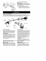
32cc/1.9 cu.in. 2-Cycle
GASOLINE WEEDWACKER
®
Model No.
358.791042
•
Safety
• Assembly
• Operation
• Maintenance
• Parts List
•
Espa6ol,
p. 23
WARNING:
Read and follow all Safety Rules and Operating
Instructions
before first use of this product.
For answers
Call 7 am-7
to your questions about this product:
pm, Mon.-Sat.,
or 10 am-7 pm, Sun.
1-800-235-5878
Sears, Roebuck
545167679
_Hou,s listed are Central
and Co., Hoffman
Rev. 2
7/3/08
BRW
Estates,
]qme)
IL 60179 U.S.A.
Warranty
Storage
17
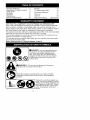
Identification of Safety Symbols
Safety Rules
Assembly
Operation
Maintenance
Statement
2
2
4
10
11
15
Troubleshooting
Table
Emissions Statement
18
19
Parts List
Spanish
21
23
Service & Adjustments
16
Parts and Ordering
ONE YEAR FULL WARRANTY
ON CRAFTSMAN
Back Cover
GAS WEEDWACKER
When used and maintained according to the operator's manual, if this product fails
due to a defect in material or workmanship within one year from the date of purchase, return it to any Seats store, Sears Service Center, or other Craftsman outlet in
the United States for free repair (or replacement if repair proves impossible).
This warranty excludes cutting line, spark plug and air filter, which are expendable
parts that can wear out from normai use in less than one year.
This warranty applies for only 90 days from purchase date if this product is ever
used for commercial or rental purposes.
This warranty gives you specific legal rights, and you may also have other rights
which vary from state to state.
Sears, Roebuck and Co., Hoffman E_tates, IL 60179
@
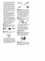
_DANGER:
Use only specified trimmer
head, spool, and recommended trimmer
line. Never use blades, flailing devices,
wire, rope, string, etc. This attachment is
designed for line trimmer use only. Failure
to follow these instructions may result in
serious injury.
®®
1
I&
I
improper use can cause serious injury.
This unit can be dangerous!
I_WARNING:
Careless
or
Read the operator's manual before use. Failure to follow
instructions could result in serious injury. Save operator's
manual.
_
lently. You can be blinded or injured.
Always wear hearing protection and
safety glasses marked Z87. Always
Trimmer
wear
head
lineprotection,
can throw heavy,
objectslong
viopants, long sleeves, boots and
gloves.
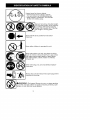
Hazard
zone
forthrown
objects.
• Trimmer
linethrows
objects
violently<
• Youandothers
canbeblinded/injured.
• Keep
children,
bystanders,
andanimals
50feet(15meters)
away.
f _
| ..._li
•_ _[I
_O
_lllll_
Ill
• I Do not wear jewelry, loose clothing,
I I or clothing with loosing hanging
IISecure
straps, ties,
etc< Theylength.
can
hair tassels,
above shoulder
J be caught in moving parts<
Assist handle to be positioned
the arrow.
only below
Never allow children to operate this unit<
Store unit indoors in a high, dry place out of the
reach of children. Store unit and fuel in area where
fuel vapors cannot reach sparks or open flames
from water heaters, electric motors or switches,
furnaces, etc.
When servicing
ment parts.
unit, use only identical replace-
Always stop unit and disconnect
cleaning or servicing.
_
spark plug before
i o_ruTeAtt_eNul_tGn;eFile _aaZmardo
rNse;e_m(iiXcP°cUrng°rs
st°rkengas°/lene
I flames,
or work that can cause sparks).
I_1
ratio of 40:1 (2<5%).
se unleaded gasoline
and two-stroke
oit mixed at a
These attachments used in combination with the specified powerhead have been
evaluated to ANSI B175.3-2003,
"Grass Trimmers and Brushcutters - Safety
Requirements".
Powerhead
Brushcutter
including trimmer attachment
......................
attachment ......................................
358<79104
358<79244
These attachments used in combination with the specified powerhead have been
evaluated to applicable ISO and EN safety requirement standards by the Swedish
Machinery Testing Institute:
Edger attachment ...........................................
Cultivator attachment ........................................
Blower attachment ..........................................
Pruner attachment ..........................................
If situations occur which are not covered in this manual, use care and
good judgment.
Ifyou need assistance, contact your Sears Service
Center or call 1-800-235-5878.
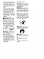
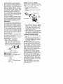
OPERATOR SAFETY
• Dress properly. Always wear safety
glasses or similar eye protection
when operating, or performing maintenance, on your unit (safety
glasses are available). Eye protection should be marked Z87.
• Always wear face or dust mask if operation is dusty.
• Always wear heavy, tong pants, long
sleeves, boots, and gloves. Wearing
safety leg guards is recommended.
• Always wear foot protection. Do not
go barefoot or wear sandals. Stay
clear of spinning line.
• Secure hair above shoulder length.
Secure or remove loose clothing or
clothing with loosely hanging ties,
straps, tassels, etc> They can be
caught in moving parts.
• Being fully covered also helps protect you from debris and pieces of
toxic plants thrown by spinning line.
• Stay Alert. Do not operate this unit
when you are tired, ill, upset or under the influence of alcohol, drugs,
or medication. Watch what you are
doing; use common sense.
A'l
IllWARNING:
When using gardening appliances, basic safety precautions must always be followed to
reduce the risk of fire and serious
injury. Read and follow all instructions.
This power unit can be dangerousf Operator is responsible for following
instructions and warnings on unit and in
manual. Read entire operator's manual
before using unit! Be thoroughly familiar
with the controls and the proper use of
the unit. Restrict the use of this unit to
persons who have read, understand,
and will follow the instructions and
wamings on the unit and in the manual.
Never allow children to operate this unit.
OPERATOR'S
MANUAL
SAFETY
ON THE
358<79240
358<79241
358<79242
358<79245
INFORMATION
UNIT
_ DANGER:
Never use blades
with line trimmer attachment. Never
use flailing devices with any attachment, This unit (when used with supplied line trimmer attachment) is designed for line trimmer use only. Use
of any other accessories with line trimmer attachment will increase the risk
of injury.
4
• Wear
hearing
protection.
• Never
startorruninside
aclosed
room
orbuilding.
Breathing
exhaust
fumes
cankill.
• Keep
handles
freeofoilandfuel.
• Always
keepengine on the right
hand side of your body.
• Hold the unit firmly with both hands.
• Keep trimmer head (or other optional attachment) below waist tevel and
away from all parts of your body. Do
not raise engine above your waist.
• Keep all parts of your body away
from muffler and spinning line (or
other optional attachment). A hot
muffler can cause serious burns.
• Keep firm footing and balance. Do
not overreach or use from unstable
surfaces such as ladders, trees,
steep slopes, rooftops, etc.
• Use only in daylight or good artificial
light.
• Use only for jobs explained in this
manual (or manuals for optional attachments).
UNIT / MAINTENANCE
SAFETY
Ai_WARNING:
Stop unitand disconnect the spark plug before performing maintenance (except carburetar adjustments).
• Look for and replace damaged or
loose parts before each use. Look
for and repair fuel leaks before use.
Keep in good working condition.
• Replace trimmer head parts that are
chipped, cracked, broken, or damaged in any oti_er way before using
tile unit.
• Maintain unit according to recommended procedures. Keep cutting
line at proper length.
• Use only Craftsman brand replacement line. Never use wire, rope,
string, etc.
• Install required shield properly before
using the unit. Use only specified trimmer head; make sure it is properly
installed and securely fastened.
• Make sure unit is assembled correctly as shown in this manual.
• Make carburetor adjustments with
lower end supported to prevent line
from contacting any object.
• Keep others away when making carburetor adjustments.
• Use only recommended
Craftsman
accessories and replacement parts.
• Have all maintenance and service
not explained in this manual performed by a Sears Service Center.
FUEL SAFETY
• Mix and pour fuel outdoors.
• Keep away from sparks or flames.
• Do not smoke or allow smoking near
fuet or the unit or while using the unit.
• Avoid spilling fue! or oil. Wipe up alt
fuel spills before starting engine.
• Move at least t0 feet (3 meters)
away from fueling site before starting engine. Stop engine and allow it
to cool before removing fue{ cap.
• Empty the _el tank before storing or
transporting the unit. Use up fuel left
in the carburetor by starting the engine and letting it run until it stops.
• Store unit and fiJel in area where fuel
vapors cannot reach sparks or open
flames from water heaters, electric
motors or switches, fiJrnaces, etc.
• Always store gasoline in a container
approved for flammable liquids.
TRANSPORTING
AND STORAGE
• Stop the unit before carrying.
• Allow engine to cool before storing
or transporting in vehicle.
• Empty the fuel tank before storing or
transporting the unit. Use up fuel left
in the carburetor by starting the engine and letting it run until it stops.
• Store unit and _el in area where fiJel
vapors cannot reach sparks or open
flames from water heaters, electric
motors or switches, fiJrnaces, etc.
• Store unit so line limiter blade cannot accidentally cause injury. The
unit can be hung by the shaft.
• Store unit out of reach of children.
This unit is not equipped with an antivibration system and is intended for
occasional use only.
SAFETY NOTICE: Exposure to vibrations through prolonged use of gasoline powered hand tools could cause
blood vessel or nerve damage in the
fingers, hands, and joints of people
prone to circulation disorders or abnormal swellings. Prolonged use in
cold weather has been linked to blood
vessel damage in otherwise healthy
people. If symptoms occur such as
numbness, pain, loss of strength,
change in skin color or texture, or loss
of feeling in the fingers, hands, or
joints, discontinue the use of this tool
and seek medical attention. An antivibration system does not guarantee
the avoidance of these problems. Users who operate power toots on a continual and regular basis must monitor
closely their physical condition and the
condition of this tool.
SPECIAL
NOTICE:
Thisunitis
equipped
withatemperature
limiting
muffler
andspark
arresting
screen
which
meets
therequirements
ofCalifornia
Codes
4442and4443.AllU.S.
forest
landandthestates
ofCalifornia,
Idaho.
Maine,
Minnesota,
NewJersey,
Oregon, and Washington require by
taw that many internal combustion engines be equipped with a spark arresting screen. If you operate in a locale
where such regulations exist, you are
legally responsible for maintaining the
operating condition of these parts.
Failure to do so is a violation of the
taw. For normal homeowner use, the
muffler and spark arresting screen wilt
not require any service. After 50 hours
of use, we recommend that your muffler be serviced or replaced by a
Sears Service Center.
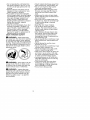
LINE TRIMMER SAFETY
HandEebar
EDGER
Blade rotates
after the
_WARNING:
Inspect the area to
be trimmed before each use. Remove
objects (rocks, broken glass, nails,
wire, etc.) which can be thrown by or
become entangled in line. Hard objects can damage the trimmer head
and be thrown causing serious injury.
• Only use the trimmer attachment for
trimming, scalping, mowing and
sweeping. Do not use the trimmer
attachment for edging, pruning or
hedge trimming.
• Cut only from your left to your right.
Cutting on right side of the shield will
throw debris away from the operator.
ADDITIONAL
SAFETY
RULES
FOR OPTIONAL ATTACHMENTS
_WARNING:
For each optional
attachment used, read entire operators manual before use and follow all
warnings and instructions in manual
and on attachment.
AJ)&WARNING:
Ensure handlebar
is installed when using brushcutter
attachment. Attach handlebar above
arrow on safety label on the upper
shaft (engine end of unit). If your
brushcutter attachment does not
include a handlebar, a handlebar
accessory kit (#530071451) is available from your Sears Service Center.
SAFETY
A_)&WARNING:
Inspect the area to
be edged before each use. Remove
ob ects (rocks, broken glass, nails,
wire, etc. which can be thrown by the
blade or can wrap around the shaft.
• Blade rotates momentarily after the
trigger is released. The blade can
seriously cut you or others.
• Allow blade to stop before removing
it from the cut.
Allow blade tostop
before removing it
fromthe cut.
• Throw away btades that are bent,
warped, cracked, broken or damaged in any other way. Replace
parts that are cracked, chipped, or
damaged before using the unit.
• Do not attempt to remove cut material nor hold material to be cut when
the engine is running or when cutting blade is moving.
• Always keep the wheel and depth
adjusting skid in contact with the
ground.
• Always push the unit slowty over the
ground. Stay alert for uneven sidewalks, holes in the terrain, large
roots, etc.
BLOWER/VACUUM
SAFETY
_
WARNING:
Inspect area before
starting unit. Remove all debris and
hard objects such as rocks, glass,
wire, etc. that can ricochet, be thrown,
or otherwise cause injury or damage
during operation.
• Do not set unit on any surface except a clean, hard area while engine
is running. Debris such as gravel,
sand, dust, grass, etc., could be
picked up by the air intake and
thrown out through discharge opening, damaging unit, property, or
causing serious injury to bystanders
or operator.
• Never
place
objects
inside
theblowertubes,
vacuum
tubes
orblower
outlet.
Always
direct
theblowing
debrisaway
frompeople,
animals,
glass,
andsolidobjects
suchas
trees,
automobiles,
wails,
etc.The
forceofaircancause
rocks,
dirt,or
sticks
tobethrown
ortoricochet
which
canhurtpeople
oranimals,
break
glass,
orcause
other
damage.
• Never
rununitwithout
theproper
_ WARNING:
Inspect the area to
equipment
attached.
When
using
cut before each use. Remove obyourunitasablower,
always
install be
jects (rocks, broken glass, nails, wire,
blower
tubes.
etc.) which can be thrown or become
• Check
airintake
opening,
blower
in the blade or trimmer line.
tubes
orvacuum
tubes
frequently, entangled
• Throw away and replace blades that
always
withengine
stopped
and
are bent, warped, cracked, broken
spark
plugdisconnected.
Keep
or damaged in any other way.
ventsanddischarge
tubes
freeof
• Install required shield properly bedebris
which
canaccumulate
and
fore using the unit. Use the metal
restrict
proper
airflow.
shield for all metal blade use.
• Never
place
anyobject
inairintake
opening
asthiscould
restrict
proper
WARNING:
Only use brushcutairflowandcause
damage
totileunit. _ter attachments
that provide a metal
• Never
useforspreading
chemicals, shield with protruding nose.
fertilizers,
orother
substances
which
maycontain
toxicmaterials.
Protruding
• Toavoid
spreading
fire,donotuse
nearleaforbrush
fires,
fireplaces,
barbecue
pits,ashtrays,
etc.
R_SO
BRUSHCUTTER
SAFETY
DANGER:
Blade can thrust vio-
lently away from material it does not
cut. Blade thrust can cause amputation of arms or legs.
mIWARNING:
Do not use trimmer
head as a fastening device for tile
blade.
• The blade continues to spin after the
throttle is reteased or engine is turned
off. The coasting blade can throw objects or seriously cut you if accidentally touched. Stop the blade by contacting the right hand side of the coasting
blade with materiat already cut.
• Use only specified blade and make
sure it is properly installed and securely fastened.
• Cut from your left to your right.
• Always use the handlebar and a
properly adjusted shoulder strap
with blade (see ASSEMBLY instructions in brushcuttar attachment
operator's manual).
CULTIVATOR SAFETY
_
WARNING:
Rotating tines can
cause serious injury. Keep away from
rotating tines. Stop the engine and
disconnect the spark plug before unclogging tines or making repairs.
_ WARNING:
Inspect the area to
be cultivated before starting the unit.
Remove all debris and hard and sharp
objects such as rocks, vines, branches, rope, string, etc.
• Avoid
heavy
contact
withsolid
objects
thatmight
stopthetines.
Ifheavy
contactoccurs,
stoptheengine
andinspect
theunitfordamage.
• Never
operate
thecultivator
without
the
tine
cover
inplace
a
nd
properly
secured.
• Keep
thetinesandguard
clear
of
debris.
• Afterstriking
aforeign
object,
stop
theengine,
disconnect
thespark
plugandinspect
thecultivator
for
damage.
Repair
before
restarting.
• Disconnect
attachment
fromthedrive
engine
before
cleaning
thetines
with
ahose
andwater
torernove
any
build-up.
Oilthetines
toprevent
rust.
• Always
wear
gloves
when
servicing
or
cleaning
thetines,
Thetinesbecome
verysharp
fromuse.
• Donotrununitathighspeed
unless
cultivating.
HEDGE
TRIMMER
SAFETY
DANGER:
RISK OF OUT: KEEP
HANDS AWAY FROM BLADE - Blade
moves momentarily after the trigger is
released, Do not attempt to clear
away cut material when the blade is in
motion. Make sure engine is stopped,
the spark plug wire is disconnected,
and the blade has stopped moving
before removing jammed material
from the cutting blade. Do not grab or
hotd the unit by the cutting blade.
Blades move
Aflow blades to stop
momentarily
before removing
after the
them from the cut
_WARNING:
thspect the area before starting the unit. Remove
all debris and hard objects such as rocks,
glass, wire, etc. that can ricochet, be
thrown, or otherwise
cause injury or
damage
during operation.
• Do not use a cutting blade that is
bent, warped, cracked, broken or
damaged in any other way. Have
worn or damaged parts replaced by
your Sears Service Center.
• Always keep unit in front of your
body. Keep all parts of your body
away from the cutting blade,
• Keep the cutting blade and air vents
clear of debris.
POLE PRUNER
SAFETY
_ WARNING:
The reciprocating
blade/rotating
chain can cause severe
injury. Inspect the unit before use. Do
not operate unit with a bent, cracked
or dull blade or dull chain. Keep away
from the blade/chain.
_WARNING:
The reciprocating
blade/rotating chain is sharp, Do not
touch. To prevent sedous injury, always
stop engine and ensure blade/chain
has stopped moving, disconnect spark
plug, and wear gloves when changing
or handling the blade or chain.
WARNING:
A coasting blade/rotating chain can cause injury while it
continues to move after the engine is
stopped. Maintain proper control of the
unit until the blade/chain has completely
stopped moving. Keep hands, face and
feet at a distance from all moving parts.
Do not attempt to touch or stop the
blade or chain when it is moving.
_ WARNING:
Falling objects can
cause severe head injury. Wear head
protection when operating this unit
with a pole pruner attachment.
WARNING:
To prevent serious
injury, do not use more than one boom
extension with a pole pruner attachment.
_
WARNING:
Keep the pruner
away from power lines or electrical
wires.
• Only use for pruning limbs or
branches up to 6 inches (15 cm) in
diameter,
• Donotoperate
theunitfaster
than
thespeed
needed
toprune.
Donot
runtheunitathighspeed
whennot
pruning.
• Always
stoptheunitwhen
workis
delayed
orwhenwalking
fromone
cutting
location
toanother.
• Ifyoustrike
orbecome
entangled
withaforeign
object,
stoptheengine
immediately
andcheck
fordamage.
Have
anydamage
repaired
bya
Sears
Sewice
Center
before
attempting
further
operations.
Discard
blades
thatarebent,warped,
cracked
orbroken.
• Stoptheunitimmediately
ifyoufeel
excessive
vibration.
Vibration
isa
signoftrouble.
Inspect
thoroughly
forloose
nuts,bolts
ordamage
before
continuing.
Contact
Sears
Service
forrepair
orreplacement
of
affected
parts
asnecessary.
SNOW
THROWER
SAFETY
,_ WARNING:
Keep hands and
feet away from the rotor when starting
or running the engine. Never attempt
to clear the rotor with the engine/motor
running. Stop engine and disconnect
spark plug before unclogging snow or
debris from discharge chute or when
adjusting vanes.
,_
WARNING:
Never lean over dis-
charge chute. Rocks or debris could
be thrown into the eyes and face and
cause serious injury or blindness.
_WARNING:
Inspect the area
where the unit is to be used. Remove
objects that could be thrown or damage the unit. Some objects may be
hidden by fallen snow -- be alert for
the possibility.
• Direct material discharge away from
glass enclosures, automobiles, etc.
• Do not run engine at high speed
while not removing snow.
• Be attentive when using the snowthrower, and stay alert for holes in
the terrain and other hidden hazards.
• Make sure the rotor will spin freely
before attaching the snowthrower to
the powerhead.
• If the rotor will not rotate freely due
to frozen ice, thaw the unit thoroughly before attempting to operate
under power,
• Keep the rotor clear of debris.
• Do not throw snow near other
people. The snow thrower could
propel small objects at high speed
causing injury.
• After striking a foreign object, stop
the engine, disconnect spark plug
and inspect the snowthrower for
damage and repair if necessary before restarting unit.
• Never operate the snowthrower near
glass enclosures, automobiles and
trucks.
• Never attempt to use the snowthrower on a roof.
• Never operate the snowthrower near
window wells, dropoffs, etc.
• Never discharge snow onto public
roads or near moving traffic.
• Clear snow from slopes by going up
and down; never across. Use caution when changing directions. Never clear snow from steep slopes.
• Let snowthrower run for a few minutes after clearing snow so moving
parts do not freeze.
• Look behind and use care when
backing up. Exercise caution to
avoid slipping or falling, especially
when operating in reverse.
• Know how to stop quickly.
CARTON
CONTENTS
5. Push the attachment into the coupler until the locking/release
button
Check
carton
contents
against
thefolsnaps into the primary hole.
lowing
list.
6. Before using the unit, tighten the
Model
388.791042
Powerhead
knob securely by turning clockwise.
Trimmer
attachment
Shield
Wing
Nut(screwed
ontoshield)
Container
ofline
Container
ofoil
Examine
parts
fordamage.
Donot
usedamaged
parts.
Upper
Locking/ Attachment
NOTE:
Ifyouneedassistance
orfind
Shaft
Release
Button
partsmissing
ordamaged,
call
1-800-235-5878.
Make sure the lockItisnormal
forthefuelfiltertorattlein _ WARNING:
ing/release
button
is locked in the pritheempty
fueltank.
hole and the knob is securely
Finding
fueloroilresidue
onmuffler
is mary
operating the unit. All
normal
duetocarburetor
adjustmentstightened before
are designed to be used in
andtesting
done
bythemanufacturer.attachments
the primary hole unless otherwise
ASSEMBLY
stated in the applicable attachment opmlWARNING:
Always stop unit
and disconnect spark plug before performing any assembiy procedures.
_WARNING:
If received
erator's manual. Using the wrong hote
could lead to serious injury or damage
to the unit.
Secondary
as-
Hole
sembled,
repeat all steps to ensure
your unit is properly assembled and att
fasteners are secure.
INSTALLING
MENT
TRIMMER
ATTACH-
CAUTION:
When installing trimmer
attachment, place the unit on a flat
surface for stability.
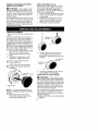
1. Loosen the coupler by turning the
knob counterclockwise.
Locking/Release
Button in Primary Hole
For optional attachments, see the ASSEMBLY section of the applicable attachment operator's manual.
ATTACHING
Coupler
_WARNING:
Shipping
protector
TIGHTEN
2.
3.
4.
Knob
Remove shipping protector from
coupler.
Remove the shaft cap from the
trimmer attachment (if present).
Position locking/release
button of
attachment into guide recess of
coupler.
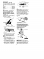
SHIELD
The shield must be
properly installed. The shieid provides
partial protection ftom the risk of thrown
objects to the operator and others and
is equipped with a line limiter blade
which cuts excess line to the proper
length. The line limiter blade (on underside of shield) is sharp and can cut you.
For proper orientation of shield, see
KNOW YOUR TRIMMER illustration in OPERATION section.
1. Remove wing nut from shield.
2. Insert bracket into slot as shown.
3. Pivot shield until bolt passes
through hole in bracket.
4. Securely tighten wing nut onto bolt.
10
ADJUSTING
PIVOTShield
sbt
THE HANDLE
_WARNING:
Bracket
/
/'
Line Limiter
Blade
When adjusting the
assist handle, be sure it remains above
the safety label and below the mark or
arrow on the shaft.
1. Loosen wing nut on handle.
2. Rotate the handle on the shaft to an
upright position; retighten wing nut.
Wing
Nut
KNOW YOUR TRIMMER
READ THiS OPERATOR'S MANUAL AND SAFETY RULES BEFORE OPERATING YOUR
UNIT Compare tile illustrationswith your unit to familiarize yourself with the location of
the various controls and adjustments. Save this manual for future reference.
Assist Handle
/
Coupler
_._
Shaft
Trimmer
Head
ON/STOP Switch
Starter
Shield
Handle
/
Primer Bulb
/
Throttle
Trigger
Line Limiter
Blade
Start Lever
ON/STOP SWITCH
The ON/STOP switch is located on tile
trigger handle and is used to stop the
engine. To stop the engine, push and
release the engine ON/STOP switch.
PRIMER BULB
The PRIMER BULB removes air from
the carburetor and fuel lines and flits
them with fuel This allows you to start
the engine with fewer pulls on the
starter rope. Activate the primer bulb
by pressing it and allowing it to return
to its original form.
START LEVER
The START LEVER helps to supply fuel
to the engine to aid in starting. Activate the starting system by moving the
start lever to the START position. DO
NOT squeeze the throttle trigger until
the engine has started and runs. After
the engine starts, allow the engine to
warm-up 5 seconds, then fully
squeeze the throttle trigger to deactivate the starting system (start lever
returns to RUN position).
COUPLER
The COUPLER enables optional attachments to be installed on the unit.
BEFORE
FUELING
STARTING
_WARNING:
ENGINE
Be sure to read
the fuel information in the safety rules
before you begin. If you do not understand the safety rules, do not attempt
to fuel your unit. Call 1-800-235-5878.
ENGINE
_ WARNING:
Remove fuet cap
slowly when refueling.
This engine is certified to operate on
unleaded gasoline. Before operation,
gasoline must be mixed with a good
11
STARTING A COLD ENGINE
quality
synthetic
2-cycle
air-cooled
engineoil.Werecommend
Craftsman NOTE: DO NOT squeeze the throttle
brand
synthetic
oil.Mixgasoline
andoil trigger until the engine has started and
ataratio
of40:1.
A40:tratio
isobruns.
tained
bymixing
3.2ounces
ofoilwith1 1. Set unit on a flat surface.
gallon
ofunleaded
gasoline.
Included 2. Slowly press the primer bulb 6
withthistrimmer
isa3.2ounce
contain- times.
erofoil.Pour
tileentire contents of this
3. Move the start lever to the START
container into 1 gallon of gasoline to
achieve the proper f_el mixture. DO
NOT USE automotive oit or marine oil.
These oils will cause engine damage.
When mixing fuel, follow instructions
printed on container.
Once oit is added to gasoline, shake
container momentarily to assure that
the fuel is thoroughly mixed. Always
read and follow the safety rules relating to fuel before fueling your unit.
IMPORTANT
Alcohol blended fuels (called gasohot
or using ethanol or methanol) can attract moisture which leads to separation and formation of acids during storage. Acidic gas can damage the fuel
system of an engine while in storage.
To avoid engine problems, empty the
fuel system before storage for 30 days
or longer. Drain the gas tank, start the
engine and let it run until the fuel lines
and carburetor are empty. Use fresh
fuel next season.
Never use engine or carburetor cleaner products in the fuel tank or permanent damage may occur.
See the STORAGE section for additional information.
HOW TO STOP YOUR UNIT
• Release the throttle trigger.
• Push and release the engine ON/
STOP switch. The switch wilt automatically return to the ON position.
Wait 5 seconds before attempting to
restart unit to allow switch to reset.
ON/STOP Switch
HOW TO START YOUR UNIT
_WARNING:
Avoid any contact
with the muffler. A hot muffler can
cause serious burns.
position.
Starter Handle
Start
Muffler
4.
This unit has the Sim-pul_
starting
system. You do not have to pull the
starter rope handle sharply or briskly. Pull starter rope handle with a
controlled and steady motion until
engine starts and runs.
5. Allow unit to run for 5 seconds, then
f,Jlly squeeze the throttle trigger to
disengage the starting system (start
lever returns to RUN position).
STARTING A WARM ENGINE
1. Squeeze and hold the throttle trigger.
2. Pull starter rope handle with a controlled and steady motion while
squeezing throttle trigger until engine starts and runs.
NOTE: Normally, the warm starting
procedure can be used within 5-t0
minutes after the unit is turned off. If
the unit sits for more than 10 minutes
without being used, it wilt be necessary to start the unit by following the
steps under STARTING A COLD ENGINE or following the starting instruction steps shown on the unit.
STARTING A FLOODED ENGINE
Flooded engines can be started by
placing the start lever to the RUN position. Fully squeeze throttle trigger.
Pull the starter rope handle repeatedly
while squeezing throttle trigger until
engine starts and runs. This could require pulling the starter rope handle
many times, depending on how badly
the unit is flooded.
If the unit still doesn't start, refer to
TROUBLESHOOTING TABLE or catt
1-800-235-5878.
12
CRAFTSMAN
®
CONVERTIBLE
FEATURE
TM
This model is equipped with a coupler
which enables optional attachments to
be installed. The optional attachments
C°uple_eide
Recess
are:
Edger .................
Cultivator ..............
Blower ................
Brushcutter
............
Pruner ................
358.79240
358.79241
358.79242
358.79244
358.79245
_WARNING:
Always stop unit
and disconnect spark plug before removing or installing attachments.
REMOVING TRIMMER ATTACHMENT (OR OTHER OPTIONAL ATTACHMENTS)
CAUTION:
When removing or installing attachments,
place the unit on a
fiat surface for stability.
1. Loosen the coupler by turning the
knob counterclockwise.
Upper
Shaft
_
WARNING:
Locking/
Release
Button
Attachment
Make sure the lock-
ing/release button is locked in the primary hole and the knob is securely
tightened before operating the unit. All
attachments are designed to be used in
the primary hole unless otherwise
stated in the applicable attachment operator's manual. Using the wrong hote
could lead to sedous injury or damage
to the unit.
Secondary
Hole
Upper Shaft
Coupler
Attachment
Locking/Release
Button in Primary Hole
TIGHTEN
2.
Knob
Press and hold the locking/release
button.
OPERATING
INSTRUCTIONS
To maximize operating efficiency, do
not run the engine for longer than 1
minute at a time at full throttle.
OPERATING POSITION
ALWAYS USE:
Locking/Release
Button
Eye Protection
Upper Shaft
Attachment
3.
While securely holding the engine
and upper shaft, pull the attachment straight out of the coupler.
INSTALLING OPTIONAL ATTACHMENTS
1. Remove the shaft cap from the attachment (if present).
2. Position locking/release
button of
attachment into guide recess of
coupler.
3. Push the attachment into the coupler until the locking/release
button
snaps into the primary hole.
4. Before using the unit, tighten the
knob securely by turning clockwise.
Long
Pants
Heavy
Cut from your right to your left.
_ WARNING:
Always wear eye
protection and hearing protection. Never
tean over the trimmer head. Rocks or
debds can ricochet or be thrown into
eyes and face and cause blindness or
other serious injury.
13
When operating unit, stand as shown
and check for the following:
• Wear eye protection, hearing protection and heavy clothing.
• Hold trigger handle with right hand
and assist handle with left hand.
• Hold unit so that engine is below
waist level.
• Cut only from your dght to your left
to ensure debris is thrown away from
you. Without bending over, keep tine
near and parallel to the ground and
not crowded into material being cut.
Do not run the engine at a higher speed
than necessary. The cutting line will cut
efficiently when the engine is run at less
than full throttle. At lower speeds, there
is less engine noise and vibration.
Always release the throttle trigger and
allow the engine to return to idle
speed when not cutting.
HOW TO STOP YOUR UNIT
• Release the throttle trigger.
• Push and release the engine ON/
STOP switch.
CUTTING METHODS
_WARNING:
Use minimum
speed and do not crowd the line when
cutting around hard objects (rock,
gravel, fence posts, etc.), which can
damage the trimmer head, become
entangled in the line, or be thrown
causing a serious hazard.
• The tip of the line does the cutting.
You will achieve the best performance and minimum line wear by not
crowding the line into the cutting
area. The right and wrong ways are
shown below.
Tip of the Line
Line Crowded Into
Does The Cutting
Work Area
• During light duty cutting,
• Near objects around which the line
can wrap such as small posts,
trees or fence wire.
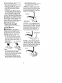
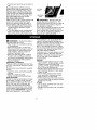
TRIMMING - Hold the bottom of the
trimmer head about 3 inches (8 cm)
above the ground and at an angle, Allow only the tip of the line to make
contact with vegetation. Do not force
trimmer line into work area.
Trimming
3 inches (8 cm)
above ground
SCALPING - The scalping technique
removes unwanted vegetation down to
the ground, Hold the bottom of the trimmer head about 3 inches (8 cm) above
the ground and at an angle, Allow the
tip of the line to strike the ground
around trees, posts, monuments, etc.
This technique increases line wear.
Scalping
3 inches (8 cm)
above ground
MOWING - Your trimmer is ideal for
mowing in places conventional lawn
mowers cannot reach. In the mowing
position, keep the line parallel to the
ground. Avoid pressing the head into
the ground as this can scalp the
ground and datum, e the tool.
Mowing
Right
....
_/rong
• The line wilt easily remove grass
and weeds from around walls,
fences, trees and flower beds, but it
also can cut the tender bark of trees
or shrubs and scar fences.
• For trimming or scalping, use less
than full throttle to increase line life
and decrease head wear, especially:
14
SWEEPING - The fanning action of the
rotating line can be used to blow away
toose debris from an area. Keep the tine
parallel to and above the area surface
and swing the tool from side to side.
J
MAINTENANCE
WARNING:
SCHEDULE
Disconnect
the spark plug before
performing
maintenance
except for carburetor adjustments.
CARE & MAINTENANCE
TASK
WHEN TO PERFORM
Check for loose fasteners
Before each use
Check for damaged
and parts
Before each use
or worn parts
After each use
Inspect and clean unit and decals
Clean air filter
Inspect muffler and spark arresting
Replace
Every 5 hours of operation
screen
Every 50 hours of operation
spark plug
GEN ERAL RECOM MENDATIONS
The warranty on this unit does not
cover items that have been subjected
to operator abuse or negligence. To
receive full value from the warranty,
the operator must maintain unit as
instructed in this manual. Various adjustments wilt need to be made periodically to properly maintain your unit.
CHECK FOR LOOSE
FASTENERS AND PARTS
• Spark Ptug Boot
• Air Fitter
• Housing Screws
• Assist Handle Screw
• Debris Shield
CHECK FOR DAMAGED
OR
WORN PARTS
Contact Sears Service Center for replacement of damaged or worn parts.
• ON/STOP Switch - Ensure ON/STOP
switch functions properly by pushing
and releasing the switch. Make sure
engine stops. Wait 5 seconds before
attempting to restart unit to allow
switch to reset. Restart engine and
continue.
• Fuel Tank - Discontinue use of unit
if fuel tank shows signs of damage
or leaks.
• Debris Shield - Discontinue use of
unit if debris shield is damaged.
Yearty
INSPECTAND
CLEAN UNITAND DECALS
• After each use, inspect complete
unit for toose or damaged parts.
Clean the unit and decals using a
damp ctoth with a mild detergent.
• Wipe off unit with a clean dry cloth.
CLEAN AIR FILTER
A dirty air filter decreases engine performance and increases fuel consumption and harmful emissions. Always
clean after every 5 hours of operation.
1. Ctean the cover and the area
around it to keep dirt from falling
into the carburetor chamber when
the cover is removed.
2. Remove parts by pressing button
to release air fitter cover.
NOTE: To avoid creating a fire hazard
or producing harmful evaporative
emissions, do not clean filter in gasoline or other flammable solvent.
3. Wash the fitter in soap and water.
4. Allow filter to dry.
5. Repiace parts.
Button
Ai?i,te
15
INSPECT MUFFLER AND SPARK
ARRESTING
SCREEN
_WARNING:
The muffler on this
product contains chemicals known to
the State of California to cause cancer.
As your unit is used, carbon deposits
build up on the muffler and spark arresting screen.
For normal homeowner use, however,
the muffler and spark arresting screen
will not require any service. After 50
hours of use, we recommend that your
muffler be serviced or replaced by your
Sears Sen4ce Center.
LINE REPLACEMENT
• Always use Craftsman replacement
line.
Choose the line size best suited for
the job at hand. Red line is designed
for cutting grass and small weeds.
The black colored line is designed for
cutting larger weeds and light brush.
NOTE: Before inserting new line into
the holes in the cutting head, identify
the proper holes. Follow directions as
shown on the line glide plate.
1. Remove the old line and line glide
plate from the cutting head.
2. Clean entire surface of cutting
head.
3. Reinstall Iine glide plate (see illustration). Align arrow with:
(_)
when using medium (red) or
large (black) line
(D
when using Iines with diameter
smaller than medium (red) line
(optional)
REPLACE SPARK PLUG
Replace the spark plug each year to
ensure the engine starts easier and
runs better. Set spark plug gap at
0.025 inch (0.5 mm). Ignition timing is
fixed and nonadjustable.
1. Twist, then pull off spark plug boot.
2. Remove spark plug from cylinder
and discard.
3. Reptace with Champion RCJ-6Y
spark plug and tighten securely
with a 3/4 inch socket wrench.
4. Reinstall the spark plug boot.
!
Positioning
5.
Pull the line and make sure the
line is against the hub and extended fuIt through the positioning
tunnels,
Line against
"the hub
Tunne{
6,
Line glide
Arrow
Cutting head
NOTE: Line glide plate must
stalled in cutting head before
new line.
4. Insert both ends of your
through the proper holes
side of the cutting head.
be reininserting
line
in the
Correctly installed tine will be the
same length on both ends.
CARBURETOR
ADJUSTMENT
_ WARNING:
Keep others away
when making idle speed adjustments.
The trimmer head witt be spinning during most of this procedure.
Wear your
protective equipment and observe alt
safety precautions. After making adjustments, the trimmer head must not
move or spin at idle speed.
The carburetor has been carefully set
at the factory. Adjustments may be
necessary if you notice any of the following conditions:
• Engine will not idle when the throttle is
released.
16
• Thetrimmer
headmoves
orspins
at
idle.
Make
adjustments
withtheunitsupAir Filter
ported
sothecutting
attachment
isoff
theground
andwillnotmake
contact Cover
withanyobject,
Hold
theunitbyhand
while
running
andmaking
adjustments.
Keep
allparts
ofyourbody
away
f_om Idle S
Screw
thecutting
attachment
andmuffler.
Idle Speed Adjustment
Allow engine to idle. Adjust speed until
engine runs without trimmer head
moving or spinning (idle too fast) or
engine stalling (idle speed too slow).
• Turn idle speed screw clockwise to
increase engine speed if engine
stalls or dies.
• Turn idle speed screw counterclockwise to decrease engine speed if
trimmer head moves or spins at idle.
=&
m_WARNING:
Perform the following steps after each use:
• Allow engine to cool before storing
or transporting,
• Store unit and fuel in a welt ventilated area where fuel vapors cannot
reach sparks or open flames from
water heaters, electric motors or
switches, furnaces, etc.
• Store unit with all guards in place.
Position unit so that any sharp object cannot accidentally cause injury.
• Store unit and fuel well out of the
reach of children.
SEASONAL
STORAGE
Prepare unit for storage at end of season or if it wilt not be used for 30 days
or more.
If your unit is to be stored for a period
of time:
• Clean the entire unit before lengthy
storage.
• Store in a clean dry area.
• Lightly oil external metal surfaces.
FUEL SYSTEM
Empty the fuel system before storage
for 30 days or longer. Drain the gas
tank, start the engine and let it run until the fuel lines and carburetor are
empty. Use fresh fuel next season.
Under FUEUNG ENGINE in the OPERATION section of this manual, see message labeled IMPORTANT regarding
the use of gasohol in your engine.
_
- b-
WARNING:
Recheck the idle
speed after each adjustment.
The
trimmer head must not move or spin at
idle speed to avoid serious injury to
the operator or others.
If you require further assistance or are
unsure about performing this procedure, contact your Sears Service Center or call our customer assistance
help line at 1-800-235-5878.
Fuel stabilizer is an acceptable alternative in minimizing the formation of
fuel gum deposits during storage. Add
stabilizer to the gasoline in the fuet
tank or fuel storage container. Follow
the mix instructions found on stabilizer
container. Run engine at least 3 minutes after adding stabilizer.
Craftsman 40:1,2-cycle
engine oil (air
cooled) is already blended with fuel
stabilizer. If you do not use this Sears
oit, you can add a fuel stabilizer to
your fuel tank.
ENGINE
• Remove spark plug and pour 1 teaspoon of 40:1,2-cycle
engine oit (air
cooled) through the spark plug
opening. Slowly pull the starter rope
8 to 10 times to distribute oil.
• Replace spark plug with new one of
recommended
type and heat range.
• Clean air filter.
• Check entire unit for loose screws,
nuts, and bolts. Replace any damaged, broken, or worn parts.
• At the beginning of the next season,
use only fresh fuel having the proper
gasoline to oit ratio.
OTHER
• Do not store gasoline from one season to another.
• Replace your gasoline can if it starts
to rust.
17
TROUBLESHOOTING
TABLE
WARNING:
Always stop unit and disconnect spark plug before performing all of the recommended
remedies below except remedies that require
unit to be operating.
TROUBLE
CAUSE
REMEDY
Engine will not
start.
1. Engine flooded.
1 See "Starting a Flooded Engine" in
Operation Section.
2. Fill tank with correct fuel mixture
3 Install new spark plug.
4 Check for dirty fuel filter; replace.
Check for kinked or split fuel line;
repair or replace
5 Contact Sears Service (see back cover).
2. Fuel tank empty
3. Spark plug not firing.
4. Fuel not reaching
carburetor.
5. Carburetor requires
adjustment.
Engine will
not idle
properly.
1. Carburetor requires
adjustment.
2. Orankshaff seals worn.
3. Compression
low.
1. See "Carburetor
Adjustment" in
Service and Adjustments Section.
2. Contact Sears Service {see back cover).
3. Contact Sears Service (see back cover).
Engine will not
accelerate,
lacks power,
or dies under
a load
1. Air filter dirty
2. Spark plug fouled.
1 Clean or replace air filter.
2 Clean or replace plug
and regap.
3 Contact Sears Service (see back cover).
Engine
smokes
excessively.
Engine
hot.
runs
3. Carburetor requires
adjustment.
4. Carbon buiid-up on
muffler outlet screen.
5. Compression
low.
1. Fuel mixture
incorrect
4 Contact
Sears Service (see back cover).
5 Contact
Sears Service (see back cover).
1. Empty fue_ tank and refill with
correct fuel mixture.
2. Clean or replace air filter.
3. Contact Sears Service (see back cover).
2. Air filter dirty.
3. Carburetor requires
adjustment.
1. Fuel mixture incorrect.
1. See "Fueling Engine" in Operation
section
2. Replace with correct spark plug.
3. Contact Sears Service (see back cover).
2. Spark plug incorrect.
3. Carburetor requires
adjustment.
4. Carbon build-up on
muffler outlet screen
4-. Contact Sears Service (see back cover).
18
YOUR WARRANTY RIGHTS AND OBLIGATIONS: The U.S. Environmental
Protection Agency/California Air Resources Board and Sears, Roebuck
and Co., U.S.A., are pleased to explain
the emissions control system warranty
on your year 2007 and later small offroad engine. In Califomia, all small offroad engines must be designed, built,
and equipped to meet the State's stringent anti-smog standards. Sears must
warrant the emission control system on
your small off-road engine for the periods of time listed below provided there
has been no abuse, neglect, or impropel maintenance of your small off-road
engine. Your emission control system
includes parts such as the carburetor,
the ignition system and the fuel tank
(California only). Where a warrantable
condition exists, Seals will repair your
small off-road engine at no cost to you.
Expenses covered under warranty include diagnosis, parts and labor.
MANUFACTURER'S
WARRANTY
COVERAGE: If any emissions related
_=arton your engine (as listed under
missions Controt Warranty Parts List)
is defective or a defect in file materials
or workmanship of the engine causes
the failure of such an emission related
part, file part will be repaired or replaced by Sears. OWNER'S WARRANTY RESPONSIBILITIES:
As the
small off-road engine owner, you are
responsible for the performance of the
required maintenance listed in your operator's manual. Sears recommends
that you retain alt receipts covering
maintenance on your small off-road engine, but Sears cannot deny warranty
solely for the lack of receipts or for your
failure to ensure the performance of all
scheduled maintenance. As the small
off-road engine owner, you should be
aware that Sears may deny you warrarity coverage if your small off-road
engine or a part of it has failed due to
abuse, neglect, improper maintenance,
unapproved modifications, or the use of
parts not made or approved by the original equipment manufacturer. You are
responsible for presenting your small
off-road engine to a Sears authorized
repair center as soon as a problem exists. Warranty repairs should be completed in a reasonable amount of time,
not to exceed 30 days. If you have any
questions regarding your warranty rights
and responsibilities, you should contact
your nearest authorized service center
or call Sears at 1-800-469-4663.
WARRANTY COMMENCEMENT
DATE: The warranty period begins on
the date the small off-road engine is
purchased. LENGTH OF COVERAGE:
This warranty shall be for a period of
two years from the initial date of purchase. WHAT IS COVERED: REPAIR
OR REPLACEMENT
OF PARTS. Repair or replacement of any warranted
part will be performed at no charge to
the owner at an approved Sears Service Center. If you have any questions
regarding your warranty rights and responsibilities, you should contact your
nearest authorized service center or call
Sears at 1-800-469-4663.
WARRANTY PERIOD: Any warranted part which
is not scheduled for replacement as required maintenance, or which is scheduled only for regular inspection to the
effect of "repair or replace as necessary" shall be warranted for 2 years.
Any warranted part which is scheduled
for replacement as required maintenance shall be warranted for the period
of time up to the first scheduled replacement point for that part. DIAGNOSIS:
The owner shall not be charged for
diagnostic labor which leads to the determination that a warranted part is defective if the diagnostic work is petformed at an approved Sears Service
Center. CONSEQUENTIAL
DAMAGES: Sears may be liable for damages to other engine components
caused by the failure of a warranted
part still under warranty. WHAT IS NOT
COVERED: All failures caused by
abuse, neglect, or improper maintenance are not covered. ADD-ON OR
MODIFIED PARTS: The use of add-on
or modified parts can be grounds for
disallowing a warranty claim. Sears is
not liable to cover failures of warranted
parts caused by the use of add-on or
modified parts. HOW TO FILE A
CLAIM: If you have any questions regarding your warranty rights and responsibilities, you should contact your
nearest authorized service center or call
Sears at 1-800-469-4663.
WHERE TO
GET WARRANTY SERVICE: Warranty
services or repairs shall be provided at
all Sears Service Centers. Call
1-800-469-4663.
19
MAINTENANCE, REPLACEMENT
AND REPAIR OF EMISSION RELATED PARTS: Any Sears approved
replacement part used in the performance of any warranty maintenance or
repair on emission related parts will be
provided without charge to the owner if
the part is under warranty.
EMISSION CONTROL WARRANTY
PARTS LIST: Carburetor, Ignition System: Spark Plug (covered up to maintenance schedule), Ignition Module, Muffler including catalyst, Fuel Tank
(California only). MAINTENANCE
STATEMENT: The owner is responsible
for tile performance of all required maintenance as defined in the operator's
manual
The information on the product labet indicates which standard your engine is certified.
Example: (Year) EPA Phase 1 or Phase 2 and/or CALIFORNbA.
This engine is certified to be emissions
[]
Moderate
[]
Intermediate
[]
Extended
compliant
(50 hours)
(t25 hours)
(300 hours)
20
for the following
use:
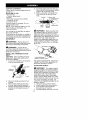
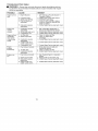
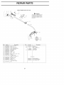
REPAIR PARTS
SEARS
2
3
4
5
6
TRIMMER
MODEL 358.791042
7
WARNING
All _pairs,
ad}ustments
and
mamtenar_ce not described in
the Operator's Manua_ must be
per[uuaed by qualified service
persoJ_rJel
8
9
15
10-'I_
17
_.
22
_
Ref
Part No.
Description
"1
2
3
4
5
6
7
8
9
10
11
12
13
530015805
530015886
530057983
530016326
530057984
530058843
530071356
530015886
545017701
530015786
530058583
530016152
530071936
Sclew alignment
Screw
Hsg Thr_lle rigi_t
Scow
Cable Retentioh
14
15
16
17
18
530016344
530071788
530052286
530015814
530071802
19
530015820
Ref.
20
21
22
Hsg Left throttle
Assy Wire
K_t Switch
Screw
Lever Trigge_
Bo_t
Assy Handle
(Incl 10¸12)
Wingnut
K_t Upper Shalt
(Incl flex, clamp & 14)
Screw
Kit Lower Shati
Limiter Line
Screw
Kit Shield Assy
(IncI 16¸17,19,20)
Bolt
23
Part No
530016152
71 85740
71 85908
71 85909
530096039
23
Description
Wingnut
Head Cutting
Tube
Twisted
Red Line
Black Line
Plate Glide
Line
Not Shown
545167679
545209101
530057296
21
Operatol Manual
Decal Shaft War_ing
Decal Upper Shaft
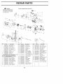
REPAIR PARTS
_
WARNING
SEARS TRIMMER
MODEL
358.791042
All repairs
adiustments
and
mainte_ance _ot deseribed in
tl_e Operator's
Manua_ mu3t
be periormed
by qualified
service personnel¸
2
9
23
i
10
24
3
11"12
13
1=4
i
15
22
18
40
i
48
43
I
i
65
Ref.
2
3
4
5
6
7
8
9
10
11
12
13
E
14
15
16
17
18
19
20
21
22
23
Part No.
Description
330047721
330071717
330015843
Bulb Purge
Kit ChokeLever
Screw tank
330049386
330014362
330071404
330069216
330015775
i45000501
i45082301
330015849
i45000601
Cap Fuelwjet
Assy Fuel pickup
Kit Fuelline
Kit Fuel/Purge line
Screw
Cover Air box
Filter Ai_
Sclew Carb
Box Air
345006017
Kit Oarbassy(OlU
e: HepaEr Klls are no1 avaE_able
for this carburetorl
i45030102
i45109602
330015771
330015952
i45000701
i45030102
330027593
330029781
330016064
i30015875
Seal Carb (kit}
Assy Fuel Tank
Sclew Cl_nkcase
Scl_w Shroud
Assy Rear ShJpud
O Hng Shroud (kit}
Valve Reed
Stop Reed
Sclew Reed stop
Screw Retaihe_
Ref.
W32)
Part No.
Description
Ref.
Part No.
24
25
26
27
28
29
30
31
32
33
34
530055492
530054941
530054834
545050409
545081601
530015787
530019158
Isolatol T_nk
Ret Tank
Handle Starter
Kit Rope
BeaHng Inne_
Retaine_
Seal
47
48
49
50
51
52
530055122
530150247
530010960
530015162
530012594
530071998
530032102
530015789
530028807
545081901
35.
545006037
53
54
55
56
57
58
545030102
530058846
530016387
545030102
545033201
545081871
36.
37
38
39
40
41
42
43
44
45
46
530055524
530016463
530055620
530015775
545115201
545050408
545054901
530019182
530016386
530059278
530094189
Bea_ng Outer
Ret C_nksha_
Assy Crankshaft
Assy Crankcase
(Inc[ 28,2930,31)
Assy C'caselC'shaff
(Inc[ 32,3334)
Assy F[ywhee_
Washer
Space_
Sc_÷w Baffle
Plate Baffle
Kit Pulley
Spring Starter
Grommet
Scl÷w
F,'hsg
Assy Fan Housing
Washe_ Crutch
59
60
61
62
63
64
530012586
Champion
530001624
530039229
530016357
545030102
65
545026801
22
Description
Assy Clutch
Assy Drum/Adapte_
Assy Conn Rod
Ret Piston pin
Ring Piston
Kit Piston
(_ncl 50,51)
Gasket Cylinder(kit)
Assy Leadwire
Bo_t Muffler 1_ ¸' 20
Gasket Muffler (kit)
Shield
Kit Muffie_
(Incl 55,56,57)
Cylinder
Plug Spa_(ROJ
6Y)
Bo_t Oyl 1_ ¸' 20
Module Ignition
Screw Module
Kit GaskePSeal
( Incl 14,19, 53,56)
Assy Throttle cable