1
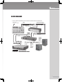
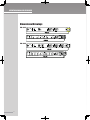
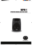
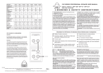
XO Series Crossovers
XO Series Crossovers
OPERATING MANUAL AND USER GUIDE
XO - 204 / XO - 206
www.wharfedalepro.com
OPERATING MANUAL AND USER GUIDE
IMPORTANT WARNINGS & SAFETY INSTRUCTIONS
1. READ ALL INSTRUCTIONS carefully and become familiar with the features and functions of these
products before operating them.
2. RETAIN THESE INSTRUCTIONS for future reference.
3. COMPLY WITH ALL WARNINGS – All warnings and instructions for this product should be adhered to.
4. USE WITH AMPLIFIERS – In order to avoid damage to drivers and other equipment, it is advisable to
establish and follow a routine for powering up and powering down a sound system. With all system
components connected, turn on source equipment (mixers, signal processors, record and playback
units, etc.) BEFORE powering up amplifiers. Transient voltages from powering up source equipment
can damage speakers if amplifiers are already turned on. Make sure that amplifier volumes are
set to their minimum settings and power up any system amplifiers LAST. It is recommended that
all system components be allowed to stabilize for several seconds before any source signals are
introduced or level setting adjustments are made. Similarly, when shutting systems down, turn all
amplifiers off first, before powering down any other system components.
5. CABLES – Always use shielded or microphone cables for connection between amplifiers and other
electronic devices. Use only approved speaker cables with proper connectors.
6. MAINS SUPPLY AND SAFETY – The main operating voltage of Wharfedale electronics is shown on the
rear panel of the device. If it does not match the voltage in your area, contact your dealer.
7. CAUTION – Professional sound reinforcement systems are capable of generating very high sound
pressure levels and use high voltage. Use care with placement and operation to avoid exposure to
excessive volume levels, water or moisture.
8. SERVICE – There are no user serviceable parts inside this product. Users should not attempt to service
this product. Warranty nullification could result if this is attempted.
1
XO Series
TABLE OF CONTENTS
1. Important Warnings & Safety Instructions……………………………....….… 1
2. What about the XO Series Crossovers?………………………………………… 3
3. Introduction/Overview…………………………….……….............................. 4
4. Features……………………….…………………………………….……………..... 5
5. Setting up/ Connections/ Wiring……………………………………................ 7
6. Specifications …………………………………….………………………….……… 11
7. Dimensional Drawings…………………………………….............................. 12
8. Warranty…………………………..……....…………………………..……........... 12
2
XO Series
INTRODUCTION
Wharfedale XO Series Crossovers are the result of many years of experience in the use,
design and manufacturing of professional sound reinforcement products. We take great
pride in engineering and building every Wharfedale Pro product and wish to thank you for
entrusting us with your sound.
From the time Gilbert Briggs built his first loudspeaker in 1932, to the present, Wharfedale
Professional products have maintained the same standard of quality in components,
workmanship and performance. Actually, Wharfedale is one of a few present day
manufacturers that design, engineer and build all of their own electronics.
Please take a few minutes to read this manual completely in order to ensure that you get
the most out of your system.
XO SERIES CROSSOVER OVERVIEW:
The XO Series crossovers are accurate, high quality, frequency dividing networks. This
allows you to tailor your system to make it sound great. With low distortion and flexible
features, these crossovers are the right tools to bring to the show.
The XO Series has many user-friendly features. These easy to adjust and use features
include: variable input gain and frequency select controls, Subwoofer output, balanced and
unbalanced input and output jacks, phase switch, mute switch, and a soft limit switch.
4
OPERATING MANUAL AND USER GUIDE
FEATURES
5
♦
Two models:
• XO-204 - 2-way
• XO-206 - 3-way
♦
Variable Crossover Frequency:
• XO-204: 60Hz – 1kHz with 10x switch
• XO-206: 60Hz – 1kHz (LOW/MID), 1kHz - 9kHz (MID/HIGH)
♦
Variable Input Gain: ∞ to +6dB
♦
Easy to read LED meters
♦
1/4” TRS Mono Subwoofer output (balanced/ unbalanced)
♦
1/4” TRS balanced/unbalanced inputs/outputs
♦
Front panel switches for easy access:
• HPF - 40Hz/ Flat
• Mute for each output: low, (mid), high
• Phase switch for each output: low, (mid), high
• Soft Limit switch for each output: low, (mid), high
XO Series
BLOCK DIAGRAM
TYPICAL WIRING DIAGRAM FOR THE XO SERIES CROSSOVER IN SYSTEM SETUP
SIGNAL INPUT
MIC, CD etc. TO MIXER
MIXER
OUTPUT
OUTPUTS FROM GRAPHIC
EQUALISER TO CROSSOVER
INPUT TO
GRAPHIC EQUALISER
SEPARATE
HIGH/MID
AND LOW
OUTPUTS TO
AMPLIFIER(S)
FROM
CROSSOVER
INPUTS TO CROSSOVER
SEPARATE
SPEAKER
OUTPUT TO
HIGH/MID
SPEAKER
FROM
AMPLIFIER
INPUTS TO AMPLIFIER(S)
SEPARATE
SPEAKER
OUTPUT TO
LOW
FREQUENCY
SPEAKER
FROM
AMPLIFIER
= SIGNAL (SHIELDED) CABLE
= LOUDSPEAKER (NON-SHIELDED) CABLE
6
OPERATING MANUAL AND USER GUIDE
SETTING UP
The XO Series Crossovers are easy to install and operate.
Before plugging in the XO Series Crossovers, or any electrical audio device, be sure that the
power switch is in the off position, the volume control is all the way down (at 0 level) and all
audio connections are made.
After power-up, you will need to set up the system; setting the crossover frequencies. Avoid
distortion (or overdriving the input) as it can damage your system in the long term.
CONNECTIONS / WIRING
Connecting XO Series Crossovers to your system is straightforward. You simply plug in your
cables (microphone or line level) from the output of the mixer to the input of the crossover;
then from the crossover output to the next component in your system, often it is an amplifier.
Always use good quality microphone (2 conductor + shield) cable. After you plug in the
components, you must adjust the crossover frequencies and their relative levels to produce
the best sound.
7
XO Series
Crossover Adjustments:
• The XO Series Crossovers are ideal tools to make set up and operation of your system
easy and accurate.
• Your best starting place is to follow the loudspeaker manufacturer ’s recommended
crossover points.
• Adjust the crossover points of the High Pass and Low Pass outputs to match the
frequencies recommended by the manufacturer.
• You will need to determine the correct output level of the low pass, the high pass and
subwoofer outputs. This is best done with an RTA, but you can get close using your ears.
It is similar to mixing the band, whatever sounds the best will be close.
• Watch the meters on the amplifiers to make sure the input level is not clipping (i.e. Too
much voltage on the amplifier’s input)
• In a simple system, the next component is the amplifier. Because your previous
adjustments have resulted in the cleanest, loudest sound coming from the mixer to the
EQ, it is not uncommon for the volume controls on the amplifier to be less than maximum
(a/k/a “11”). Don’t worry, this means you have plenty of room to get louder. If your
amplifier volume control is “max’d out” when you are at this point in the setup, you have
no place to go. You must add to your system; either more amps or more speakers.
• The bottom line is to keep watch over your meters, they will tell you if the sound levels
throughout the system are in keeping with good practices.
8
OPERATING MANUAL AND USER GUIDE
Tuning the Room:
A continuously variable frequency crossover is a very valuable tool for the traveling
musician. It allows you to get the best sound in a variety of venues. As we know, all rooms
are not created equal. They have their own personality. That is to say, your sound system
will not sound the same from room to room. Using equalisers and crossovers correctly will
help you maintain “your sound”.
• The controls on the crossover provide level adjustment to the frequency range you send
to the amplifier and ultimately the loudspeakers.
• To tune the system to the room, it takes some practice and patience. Remember to find
out the speaker manufacturer's recommended crossover frequencies for the various
elements in order to set the crossover accurately. Be careful when doing this by "ear".
What sounds right to you may be wrong for the components' long-term reliability. To be
safe, set the output level controls all at maximum so that they are at the same output
level (at lower settings, potentiometer tolerances could cause them to be different) then
counter-adjust (lower) the crossover's input level to avoid over-driving the power amps.
• When your ear gets calibrated, you can tune the system by ear.
• Use a reference-test CD or tone generator to play sine wave tones ranging from 50
to 16k Hz through the system and adjust the frequency response of the system so the
sound from the bass, mid and high frequency speakers is about the same level. Minor
adjustments by ear can be made later, but only minor adjustments.
• Leave the crossover alone until the next gig or the room changes significantly. However,
if it changes too much, it is too late to run the above procedure and you must “do it by
ear”.
9
XO Series
SPECIFICATIONS
XO-204
XO-206
Connectors:
1/4" TRS (pin 2 hot)
1/4" TRS (pin 2 hot)
Input Impedance:
Balanced 20k ohm, unbalanced 10k Balanced 20k ohm, unbalanced
INPUT/ OUTPUT
ohm
10k ohm
Max Input Level:
+20dBu balanced or unbalanced
+20dBu balanced or unbalanced
Output Impedance:
Balanced/ unbalanced 100ohm
Balanced/ unbalanced 100100ohm
Max Output Level:
+21dBu balanced/unbalanced into
Subwoofer Output
1/4" TRS (pin 2 hot)
1/4" TRS (pin 2 hot)
Frequency Range
60Hz-10kHz
60Hz -10kHz
Frequency Response:
<10Hz to >40kHz, +2/-3dB
<10Hz to >40kHz, +2/-3dB
HUM AND NOISE
-95dB
-95dB
Signal-to-Noise:
90 dB
90 dB
THD + Noise:
<0.004%
<0.004%
Interchannel Crosstalk:
<-80dB, 20Hz to 20kHz
<-80dB, 20Hz to 20kHz
Operating Voltage:
100VAC 50/60Hz, 120VAC 60Hz,
100VAC 50/60Hz, 120VAC 60Hz,
Power consumption:
230VAC 50/60Hz
230VAC 50/60Hz
Mains Connection:
12W
16W
DIMENSIONS/WEIGHT
IEC receptacle
IEC receptacle
Dimension:
482x 250 x 46mm
482 x 250 x 46mm
Weight
2.92 kg
2.97 kg
+21dBu balanced/unbalanced
SYSTEM PERFORMANCE
FUNCTION SWITCHES
Soft limit:
HPF
Phase
POWER SUPPLY
10
OPERATING MANUAL AND USER GUIDE
Dimensional Drawings
XO-204
XO-206
11
XO Series
WHARFEDALE PRO LIMITED WARRANTY
Wharfedale Pro products are warranted of manufacturing or material defects for a period of one
year from the original date of purchase. In the event of malfunction, contact your authorized
Wharfedale Pro dealer or distributor for information.
*Be aware that warranty details may differ from country to country. Contact your dealers or
distributor for information. These terms do not infringe your statutory rights.
12
Wharfedale Professional
IAG HOUSE Sovereign Court, Ermine Business Park Huntingdon, Cambs, PE29 6XU, England
www.wharfedalepro.com
Wharfedale Professional reserves the right to alter or improve specifications without notice.
All rights reserved © 2008 Wharfedale Pro. Wharfedale Pro is a member of the International Audio Group (IAG).