1
PC-104/106 SPRINKLER SYSTEM CONTROLLER
INSTALLATION INSTRUCTIONS
Rain Bird Rain Clocks are designed for use with all standard residential 24
volt AC electric valves regardless of brand. However, some older brass electric valves and commercial duty plastic valves may have power requirements
higher than this series is designed for
STEP 1: MOUNT THE TIMER
Location: Select a location inside a building,
and within six feet of a grounded electrical
outlet. This is not an outdoor timer. Do not
mount it where it is exposed to any of natures elements. If it must be outside,
be sure to use an outdoor enclosure and a
weatherproof electrical connection.
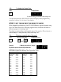
Lift
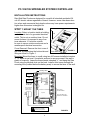
Cover Removal: Remove the front cover of
the timer by depressing the bottom tab and
lifting as shown in Figure 1.
FIGURE 1
Press Here
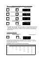
Mounting: Mount the timer to a wall using two #10 screws installed at centers
13
3 /16" apart at eye level. Use plastic anchors to secure screws if the wall is
plastic or masonry. Leave the screw heads extended ¼ " and hang the Rain
Clock using the keyhole slots on the back. Install a third screw through the
mounting hole (located below the battery area) to secure the timer to the wall.
Mounting Holes
FUSE
1
/2A 250V 3AG
OR
YELLOW
1
RED
2
FUSE
3
/4A 250V 3AG
BLUE
3
Station
Output
Terminals
AS INDICATED
ON THE UNIT
Plug Transformer
into 120 volt AC
electrical outlet
4
5
6
ONLY ON SIX
STATION MODELS
Key Pad
MV
ONLY ON PUMP START
MASTER VALVE MODELS
9 Volt Battery
Mounting Hole
To
Control
Valves
!
ATTENTION
Battery must be installed
to ensure proper operation.
2
FIGURE 2