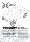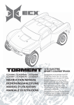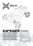
1
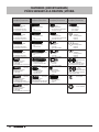
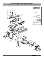
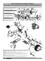
boost
TM
1/10 Electric buggy
ECX3000 | ECX3000AU | ECX3100 | ECX3100AU
Instruction Manual
Bedienungsanleitung
Manuel d’utilisation
MANUALE
Congratulations on your purchase of the Electrix
RCTM BoostTM Buggy. This 1/10-scale model
introduces you to the sport of RC driving.
Herzlichen Glückwunsch zum Kauf des Electrix
RCTM CircuitTM Stadium Truck. Dieses 1/10 Scale
Model öffnet Ihnen die Welt des RC Car Sports.
Nous vous félicitons pour l’achat du Electrix RCTM
CircuitTM Stadium Truck. Ce modèle 1/10 vous
introduit au sport de la conduite RC.
Congratulazioni per l’acquisto di questo RC Circuit
Stadium Truck Electrix. Questa vettura in scala
1/10 vi introdurrà nel mondo dei modelli RC.
EN
NOTICE
All instructions, warranties and other collateral documents are subject to change at the sole discretion of Horizon Hobby, Inc.
For up-to-date product literature, visit www.horizonhobby.com and click on the support tab for this product.
Meaning of Special Language:
The following terms are used throughout the product literature to indicate various levels of potential harm when operating this product:
NOTICE: Procedures, which if not properly followed, create a possibility of physical property damage AND little or no possibility of injury.
CAUTION: Procedures, which if not properly followed, create the probability of physical property damage AND a possibility of
serious injury.
WARNING: Procedures, which if not properly followed, create the probability of property damage, collateral damage, and serious injury
OR create a high probability of superficial injury.
WARNING: Read the ENTIRE instruction manual to become familiar with the features of the product before operating.
Failure to operate the product correctly can result in damage to the product, personal property and cause serious injury.
This is a sophisticated hobby product and NOT a toy. It must be operated with caution and common sense and requires some basic mechanical ability. Failure to operate this Product in a safe and responsible manner could result in injury or damage to the product or other
property. Do not attempt disassembly, use with incompatible components or augment product in any way without the approval of Horizon
Hobby, Inc. This manual contains instructions for safety, operation and maintenance. It is essential to read and follow all the instructions
and warnings in the manual, prior to assembly, setup or use, in order to operate correctly and avoid damage or serious injury.
Safety Precautions and Warnings
As the user of this product, you are solely responsible for operating
in a manner that does not endanger yourself and others or result in
damage to the product or the property of others.
This model is controlled by a radio signal subject to interference
from many sources outside your control. This interference can cause
momentary loss of control so it is advisable to always keep a safe
distance in all directions around your model, as this margin will help
avoid collisions or injury.
Age Recommendation: Not for children under 14 years.
This is not a toy.
• Never operate your model with low transmitter batteries.
• Always operate your model in an open area away from cars,
traffic or people.
• Never operate the model in the street or in populated areas
for any reason.
• Carefully follow the directions and warnings for this and any
optional support equipment (chargers, rechargeable battery
packs, etc.) you use.
• Keep all chemicals, small parts and anything electrical out
of the reach of children.
• Moisture causes damage to electronics. Avoid water exposure
to all equipment not specifically designed and protected for
this purpose.
• Never lick or place any portion of your model in
your mouth as it could cause serious injury.
• First-time builders should seek advice from people with
building experience to operate the model correctly and
meet its performance potential.
• Exercise caution when using tools and sharp instruments.
• Take care when building, as some parts may have sharp edges.
• Immediately after using your model, do NOT touch equipment
on the model such as the motor, electronic speed control and
battery, because they generate high temperatures. You may
burn yourself seriously touching them.
• Do not put fingers or any objects inside rotating and moving
parts, as this may cause damage or serious injury.
• Be sure that your operating frequency is clear before turning
on or running your model, and never share the same frequency
with somebody else at the same time.
• Ensure that others are aware of the operating frequency
you are using and when you are using it.
• Always turn on your transmitter before you turn on the
receiver in the car. Always turn off the receiver before
turning your transmitter off.
• Keep the wheels of the model off the ground when
checking the operation of the radio equipment.
Table of Contents
Safety Precautions and Warnings.................................................2
Specifications.................................................................................3
Components...................................................................................3
Vehicle Preparations
Installing Antenna Tube and Body.................................................3
Installing Transmitter Battery .......................................................4
Installing Transmitter Antenna......................................................4
Charging the Batteries...................................................................4
Installing Vehicle Battery...............................................................5
Operation
Transmitter controls.......................................................................6
Getting Started..............................................................................7
2
boost
TM
When you are Finished..................................................................7
Setting the Gear Mesh..................................................................8
Electronic Speed Control (ESC)......................................................8
Electrical Layout.............................................................................8
Maintenance..................................................................................9
Shock Cleaning..............................................................................9
Troubleshooting Guide...................................................................9
Warranty and Repair Policy..........................................................10
Contact Information......................................................................11
FCC and Compliance Information for the European Union...........11
Fasteners.......................................................................................42
Parts Diagram...............................................................................43
EN
Specifications
Transmitter
Frequency
Modulation
Battery
Current Consumption
Size
Weight
27MHz
Pulse Proportional Modulation (PPM)
AA x 8
200mAh
17 x 23.5 x 7.5mm
382 g
Servo
Power Supply
Output Torque
Operating Speed
Size
4.8V~6V (shared with receiver)
41.66 oz (3 kg-cm)
0.23sec/60 degrees of travel
40.5 x 20 x 36.8mm
Receiver
Frequency
Intermediate Frequency
Current Consumption
Weight
Electronic Speed Control (ESC)
Input Voltage
Electric Capacity (FET)
Electric Capacity (FET)
PWM Frequency
BEC Voltage
Size
Weight
27MHz
445kHz
18mAh
15 g
7.2–8.4V
Forward 80 A/240 A
Reverse 60 A/160 A
1kHz
5 V/1 A
27 x 35 x 17.3mm
34 g - 36 g
Components
TM
TM
1. Electrix RC Boost 1/10 Buggy
2. Transmitter
1
3. Antenna Tube (ECX1087)
Included Items
4. AA (8)
5. ECX3013 Battery Charger
6.
7.
2
4
5
3
6
Note: Charger power outlet
terminals not shown.
7.2V NiMH battery (DYN1050)
Alternate Crystal Set (not shown)
Vehicle Preparations
Installing Antenna Tube and Body
1.
2.
3.
4.
5.
6.
Remove the Body Clips (ECX1048).
Remove the body.
Put the receiver antenna in the antenna tube (ECX1087).
Put the antenna tube in the chassis with loose antenna
wire extended above the tube.
Put the cap on the antenna tube.
Put the body and body clips back on the vehicle.
boost
TM
3
EN
Installing Transmitter Batteries
1. Slide panel open on bottom of transmitter.
2. Obey battery plus (+) and minus (-) diagram
in transmitter to install 8 AA batteries.
3. Slide panel closed on transmitter.
CAUTION: ALWAYS use fully charged batteries in
the transmitter. Low battery power can result in loss
of control of the RC vehicle.
NEVER install damaged batteries, batteries of mixed
types or batteries of different ages in the transmitter.
Remove exhausted batteries.
NEVER store transmitter with batteries installed.
Note: Optional AA NiMH battery charger DYN1970 is available.
Use only batteries approved for use with that charger. DYN1970
2300mAh Tx NiMH Conversion Kit: FUT, ECX.
1
2
3
Note: Alkaline AA size batteries are recommended.
Installing Transmitter
antenna
1. Put antenna in hole in top of the transmitter.
2. The collapsed antenna will be 2-1/4 inches
long when fully inserted.
3. Turn the antenna clockwise until it is tight.
1
2-1/4 in
(57mm)
2
3
Charging the Battery
Battery WARNINGS AND GUIDELINES
A. Attach battery connector to the charger correctly.
B. 7.2V NiMH battery
C. Compatible Battery Charger
Note: Charger power outlet terminals not shown
•
•
•
•
•
A
•
•
•
•
•
B
•
•
•
•
C
•
•
•
Note: The vehicle battery charger produces 500
milliAmps per hour. Divide the mAh capacity on the
label of a battery by 500 to know how long battery
charging will require. For example, an 1800mAh
battery requires 3.5 hours to charge.
4
boost
TM
•
Read all safety precautions and literature prior to use of this product.
Never allow minors to charge battery packs.
Never attempt to charge dead or damaged batteries.
Never charge a battery if the cable has been pinched or shorted.
Never allow batteries or charger to come into contact with moisture at any
time. Never charge batteries in extremely hot or cold places (recommended
between 50–80 degrees Fahrenheit or 10–27 degrees Celsius) or place
in direct sunlight.
Never leave charging batteries unattended.
Never charge batteries outside recommended levels.
Never charge damaged batteries.
Always charge batteries away from flammable materials.
Always use only NiMH rechargeable batteries. This charger cannot charge
batteries such as “heavy duty,” “alkaline battery,” or “mercury battery.”
Always connect the positive red lead (+) and negative black lead (-)
terminals of the battery to the charger terminals correctly.
Always disconnect the battery and charger after charging, and let them
cool between charges.
Always inspect the battery before charging.
Always terminate all processes and contact Horizon Hobby if the
product malfunctions.
Always make sure you know the specifications of the battery to be
charged or discharged to ensure it meets the requirements of this charger.
Never connect more than one battery pack to this charger at a time.
Always constantly monitor the temperature of the battery pack
while charging.
Always end the charging process if the charger or battery becomes hot
to the touch or starts to change form during the charge process.
EN
Installing Vehicle Battery
1. Turn the thumb nuts to remove the battery strap.
2. Install the battery.
3. Install the battery strap.
4. Turn the thumb nuts to secure the battery strap.
5. Connect the battery.
OperatioN
Operating Precautions
and Guidelines
• ALWAYS turn on your transmitter before you turn on the
receiver in the car. Always turn off the receiver before
turning your transmitter off.
• ALWAYS operate vehicle in a wide open area. Operating
the vehicle in a small space or indoors can cause overheating
at low speeds. Operating at low speed makes heat in the
electronic speed control (ESC). Overheating can damage
the vehicle and failure may result.
•
•
•
•
•
•
•
ALWAYS keep parts dry.
ALWAYS keep moving parts clean.
ALWAYS use a clear radio frequency
ALWAYS keep vehicle in sight and under control.
NEVER touch moving parts.
NEVER operate vehicle with damaged wiring.
NEVER touch hot parts.
Motor care
• Seat motor brushes by driving smoothly on a flat surface,
using the supplied Dynamite 1800mAh battery, during
use of the first battery charge.
• Prevent overheat conditions to extend motor life.
Excessive motor wear results from:
Frequent turns
Stops and starts
Pushing objects
Driving in deep sand or tall grass
Driving continuously uphill
• Over-temperature protection is installed on the ESC
to prevent circuit damage, but cannot protect the
motor from driving against heavy resistance.
boost
TM
5
EN
Transmitter Controls
AM 27MHz Transmitter Crystal
Reverse Switch
Antenna
Pull antenna out to its
full length
(ECX1067 Antenna Only)
Part #
ECX1081
ECX1082
ECX1083
ECX1084
ECX1085
ECX1086
Description
Crystal Set 1 26.995
Crystal Set 2 27.045
Crystal Set 3 27.095
Crystal Set 4 27.145
Crystal Set 5 27.195
Crystal Set 6 27.255
AM Transmitter Crystal
(Tx)
Allows you to change the direction
of steering (ST. REV) and throttle
(TH. REV) controls. (Default
settings are “N”)
AM Receiver Crystal
(Rx)
AM Rx
AM Tx
NOTICE: Paired AM crystals
must be replaced to change control
frequencies. Do NOT use FM Crystals.
Steering Trim
ST. D/R
Adjust to make the vehicle
drive straight with no input
at the steering wheel
Adjusts the amount the front wheels
move when turned left or right
(Steering Dual Rate)
Throttle Trim
Power Switch
Adjusts the neutral point of
the electronic speed control
Power on
or off the
transmitter
Steering Wheel
Battery Level Indicator
Control steering. Right and
Left steering with ST. REV
Switch on N (See ST. REV
switch)
Good battery power
Low battery power
Note: Red light will flash with an
audible signal (beep) when batteries
are low
Note: Alkaline AA size
batteries are recommended.
Throttle Trigger
Charger Port
Note: Optional AA NiMH
battery charger DYN1970 is
available. Use only batteries approved for use with that charger;
DYN1970 2300mAh Tx NiMH
Conversion Kit: FUT, ECX
Charge only rechargeable
batteries. Non-rechargeable batteries may burst
causing injury to persons
and/or damage to property.
Note: The center pin on the charge jack is positive.
6
boost
TM
Reverse
Forward
Stop
Controls power to motor for
forward or reverse
EN
Getting Started
1. Fully extend Antenna and Power on Transmitter.
2. Connect battery to Electronic Speed Control (ESC) and
power on the ESC.
3. Do a Test of Transmitter’s control of vehicle with vehicle wheels
off ground.
4. Start driving slowly and if the vehicle does not go straight, adjust steering trim dial on Transmitter.
Note: Seat motor brushes by driving smoothly on a flat surface
during use of the first battery charge.
When you are Finished
1. Power off Electronic Speed Control (ESC).
3. Disconnect Battery.
1
2
4. Remove Battery from vehicle.
2. Power off the Transmitter and Lower Antenna.
Note: To prevent damage to antenna, collapse the antenna by
pulling the lower sections in first.
boost
TM
7
EN
Setting the gear mesh
Precautions
Gear mesh has already been set at the factory, and setting it is only
necessary when changing motors or gears.
• Never touch moving parts.
• Never disassemble while batteries installed.
• Always let parts cool before touching.
Note: You must remove the vehicle’s gear cover (A) to do this
adjustment.
Proper gear mesh (how gear teeth meet) is important to the performance of the vehicle. When gear mesh is too loose, the spur gear
could be damaged by the pinion gear of the motor. If the mesh is too
tight, speed could be limited and the motor and ESC will overheat.
1. Loosen the two (2) motor screws.
2. Put a small piece of paper between the pinion and spur gears.
3. Push the gears together while tightening the motor screws.
4. Remove the paper and the gears should move a small amount.
5. Reinstall gear cover.
A
electronic Speed control (esc)
Note: When motor disconnected or damaged, beep may not
be heard.
Note: Low voltage cutoff (LVC) will stop the vehicle when the
battery gets low. The ESC will reset after approximately 10 seconds.
The vehicle can then be driven slowly back to the driver for
battery recharge.
LED
beep
beep beep
LED Status Description LED Indication
beep
beep
beep beep
beep beep beep
beep beep
beep beep beep
electrical layout
Forward
Solid Red
Reverse
Red LEDs flashing with beep
Transmitter is not
being received.
Red LEDs flashing twice
with beeps
Signal that Vehicle
battery is low.
Red LEDs flashing three
times with beeps
Motor is
overloaded or
temperature of
ESC is high.
beep beep beep
E
A
Part #
Description
A
ECX1071
Motor B
DYN1050
Battery 7.2V
C
ECX1069
Steering Servo
D
ECX1068
Receiver
E
ECX1070
Electronic Speed Control
(ESC)
Motor
B
Battery 7.2V
Note: For correct operation, Channels 1
and 2 must be used as shown in wiring
diagram. The motor can be disconnected
from the ESC at the connectors in
the wiring.
C
AM Receiver Crystal (Rx)
boost
TM
AM Rx
Channel 2
D
Receiver
Steering Servo
8
Solid Green
Channel 1
EN
Maintenance
Rear Shock Rear shock
Shock Cleaning
• Oil-filled shocks will require regular maintenance due to the
oil breaking down or getting dirty. This maintenance should be
performed after about every 3 to 5 hours of use depending
on conditions that the vehicle is used in.
• Remove the shock from the vehicle.
• Remove the cap from the shock body and dispose of fluid.
• Disassemble the shock. Clean thoroughly with DYN5505.
Dry parts before assembly.
• Assemble the shock and refill the shock body with silicone
fluid (30 weight recommended).
• Slowly move the shaft and piston up and down to
remove air bubbles.
• Move the piston to the midway point of the body and
install the cap.
• Wipe off any overflowing fluid.
• When properly filled, the piston should rebound about
3/8 in (9.5mm) after being pushed in fully.
• Install shock on vehicle.
Ride Height Adjustment
Ride height is an adjustment that affects the way the vehicle
jumps, turns and goes over bumps. Drop one end of the vehicle
from approximately 6 inches (150 mm) in height onto a flat
surface. When dropping the front of the vehicle, after the vehicle
settles make sure the front arms are equal and parallel to the flat
surface. Do the same with the rear and look at the rear to make
sure both arms are parallel with the flat surface.
Lower the front ride height to increase steering. Lower the rear
ride height to increase traction but decrease steering.
Part # Description
Part # Description
ECX3019
Shock Body Set ECX3021
Rear Shock Shaft (2) ECX1037
Shock Caps, Pistons ECX3022
Front Shock Springs (2) ECX1038
Shock Parts Set ECX3023
Rear Shock Springs (2) ECX3020
Front Shock Shaft (2) ECX1043
Shock O-Ring Set Front Shock
front shock
ECX1037
ECX1043
ECX1057
ECX1037
ECX1038
ECX3019
ECX1038
ECX1043
ECX1037
ECX3021
ECX3020
ECX3023
ECX3022
ECX1038
ECX1037
Troubleshooting Guide
Problem
Possible Cause
Solution
Short Run Time
• Battery damaged/not charged
• Motor dirty or brushes worn
• Check/change battery
• Check/clean/replace
Sluggish Action
•Motor dirty or brushes worn
• Bind in drivetrain
• Vehicle battery is not charged
• Check/clean/replace
• Clean/adjust
• Replace/recharge
Controls Reversed
• ST. REV or TH. REV
• Change switch position
Motor/ESC overheat
• Over-geared
• Install smaller pinion
Doesn’t Operate
• Transmitter batteries low
• Transmitter powered off
• ESC powered off
• Vehicle battery is not charged
• Replace/recharge
• Power On
• Power On
• Replace/recharge
Poor Range
• Transmitter batteries low
• Transmitter antenna is damaged or loose
• Receiver antenna damaged
• Motor dirty or brushes worn
• Replace/recharge
• Check/tighten
• Check/repair/replace
• Check/clean/replace
boost
TM
9
EN
Warranty and repair policy
Warranty Period
WARRANTY SERVICES
Exclusive Warranty- Horizon Hobby, Inc., (Horizon) warranties that
the Products purchased (the “Product”) will be free from defects
in materials and workmanship at the date of purchase by the
Purchaser.
Questions, Assistance, and Repairs
Limited Warranty
Horizon reserves the right to change or modify this warranty
without notice and disclaims all other warranties, express
or implied.
(a) This warranty is limited to the original Purchaser (“Purchaser”)
and is not transferable. REPAIR OR REPLACEMENT AS PROVIDED
UNDER THIS WARRANTY IS THE EXCLUSIVE REMEDY OF THE
PURCHASER. This warranty covers only those Products purchased
from an authorized Horizon dealer. Third party transactions are
not covered by this warranty. Proof of purchase is required for all
warranty claims.
(b) Limitations- HORIZON MAKES NO WARRANTY OR REPRESENTATION, EXPRESS OR IMPLIED, ABOUT NON-INFRINGEMENT,
MERCHANTABILITY OR FITNESS FOR A PARTICULAR PURPOSE OF
THE PRODUCT. THE PURCHASER ACKNOWLEDGES THAT THEY
ALONE HAVE DETERMINED THAT THE PRODUCT WILL SUITABLY
MEET THE REQUIREMENTS OF THE PURCHASER’S INTENDED USE.
(c) Purchaser Remedy- Horizon’s sole obligation hereunder shall be
that Horizon will, at its option, (i) repair or (ii) replace, any Product
determined by Horizon to be defective. In the event of a defect,
these are the Purchaser’s exclusive remedies. Horizon reserves
the right to inspect any and all equipment involved in a warranty
claim. Repair or replacement decisions are at the sole discretion
of Horizon. This warranty does not cover cosmetic damage or
damage due to acts of God, accident, misuse, abuse, negligence,
commercial use, or modification of or to any part of the Product.
This warranty does not cover damage due to improper installation,
operation, maintenance, or attempted repair by anyone other than
Horizon. Return of any Product by Purchaser must be approved in
writing by Horizon before shipment.
Damage Limits
HORIZON SHALL NOT BE LIABLE FOR SPECIAL, INDIRECT OR
CONSEQUENTIAL DAMAGES, LOSS OF PROFITS OR PRODUCTION
OR COMMERCIAL LOSS IN ANY WAY CONNECTED WITH THE
PRODUCT, WHETHER SUCH CLAIM IS BASED IN CONTRACT,
WARRANTY, NEGLIGENCE, OR STRICT LIABILITY. Further, in no
event shall the liability of Horizon exceed the individual price of the
Product on which liability is asserted. As Horizon has no control
over use, setup, final assembly, modification or misuse, no liability
shall be assumed nor accepted for any resulting damage or injury.
By the act of use, setup or assembly, the user accepts all
resulting liability.
If you as the Purchaser or user are not prepared to accept the
liability associated with the use of this Product, you are advised to
return this Product immediately in new and unused condition to the
place of purchase.
Law: These Terms are governed by Illinois law (without regard to
conflict of law principals).
10
boost
TM
Your local hobby store and/or place of purchase cannot provide
warranty support or repair. Once assembly, setup or use of the
Product has been started, you must contact Horizon directly. This
will enable Horizon to better answer your questions and service
you in the event that you may need any assistance. For questions
or assistance, please direct your email to productsupport@
horizonhobby.com, or call 877.504.0233 toll free to speak to a
Product Support representative. You may also find information on
our website at www.horizonhobby.com.
Inspection or Repairs
If this Product needs to be inspected or repaired, please use
the Horizon Online Repair Request submission process found
on our website or call Horizon to obtain a Return Merchandise
Authorization (RMA) number. Pack the Product securely using a
shipping carton. Please note that original boxes may be included,
but are not designed to withstand the rigors of shipping without
additional protection. Ship via a carrier that provides tracking and
insurance for lost or damaged parcels, as Horizon is not responsible
for merchandise until it arrives and is accepted at our facility. An
Online Repair Request is available at www.horizonhobby.com
http://www.horizonhobby.com under the Repairs tab. If you do
not have internet access, please contact Horizon Product Support
to obtain a RMA number along with instructions for submitting
your product for repair. When calling Horizon, you will be asked to
provide your complete name, street address, email address and
phone number where you can be reached during business hours.
When sending product into Horizon, please include your RMA
number, a list of the included items, and a brief summary of the
problem. A copy of your original sales receipt must be included
for warranty consideration. Be sure your name, address, and RMA
number are clearly written on the outside of the shipping carton.
Notice: Do not ship batteries to Horizon. If you have any
issue with a battery, please contact the appropriate Horizon
Product Support office.
Warranty Inspection and Repairs
To receive warranty service, you must include your original
sales receipt verifying the proof-of-purchase date. Provided
warranty conditions have been met, your Product will be repaired or
replaced free of charge. Repair or replacement decisions are at the
sole discretion of Horizon.
Non-Warranty Repairs
Should your repair not be covered by warranty the repair
will be completed and payment will be required without
notification or estimate of the expense unless the expense
exceeds 50% of the retail purchase cost. By submitting the
item for repair you are agreeing to payment of the repair without
notification. Repair estimates are available upon request. You must
include this request with your repair. Non-warranty repair estimates
will be billed a minimum of ½ hour of labor. In addition you will be
billed for return freight. Horizon accepts money orders and cashiers
checks, as well as Visa, MasterCard, American Express, and
Discover cards. By submitting any item to Horizon for inspection or
repair, you are agreeing to Horizon’s Terms and Conditions found on
our website under the Repairs tab.
EN
Contact information
Country of Purchase
Horizon Hobby
United States of America
Horizon Service Center
(Electronics and engines)
Horizon Product Support
Address
Phone Number / Email Address
4105 Fieldstone Rd
Champaign, Illinois
61822 USA
877-504-0233
Online Repair Request visit:
www.horizonhobby.com/repairs
+44 (0) 1279 641 097
[email protected]
United Kingdom
Horizon Hobby Limited
Units 1-4 Ployters Rd
Staple Tye, Harlow
Essex CM18 7NS
United Kingdom
Germany
Horizon Technischer
Service
Hamburger Str. 10
25335 Elmshorn
Germany
+49 4121 46199 66
[email protected]
France
Horizon Hobby SAS
14 Rue Gustave Eiffel
Zone d’Activité du Réveil Matin
91230 Montgeron
+33 (0) 1 60 47 44 70
[email protected]
FCC Information
This device complies with part 15 of the FCC rules. Operation is subject to the following two conditions: (1) This device may not cause
harmful interference, and (2) this device must accept any interference received, including interference that may cause undesired operation.
Caution: Changes or modifications not expressly approved by the party responsible for compliance could void the user’s authority to
operate the equipment.
Compliance Information for the European Union
Declaration of Conformity
(in accordance with ISO/IEC 17050-1)
No. HH20110212
Product(s):
Item Number(s):
Equipment class:
ECX 1/10th Scale Buggy Boost
ECX3000, ECX3100
1
The object of declaration described above is in conformity with the requirements of the specifications listed below,
following the provisions of the European R&TTE directive 1999/5/EC and EMC Directive 2004/108/EC:
EN 300-220
EN 301 489
EN 60950
Technical requirements for Radio equipment
General EMC requirements for Radio equipment
Safety
EN55022
EN55024
EN61000-3-2
EN61000-3-3
Radio disturbance characteristics
Immunity characteristics
Harmonic current emissions
Voltage fluctuations & flicker
Signed for and on behalf of:
Horizon Hobby, Inc.
Champaign, IL USA
Feb 12, 2011
Steven A. Hall
Vice President
International Operations and Risk Management
Horizon Hobby, Inc.
Instructions for disposal of WEEE by users in the European Union
This product must not be disposed of with other waste. Instead, it is the user’s responsibility to dispose of their waste
equipment by handing it over to a designated collections point for the recycling of waste electrical and electronic equipment.
The separate collection and recycling of your waste equipment at the time of disposal will help to conserve natural resources
and ensure that it is recycled in a manner that protects human health and the environment. For more information about where
you can drop off your waste equipment for recycling, please contact your local city office, your household waste disposal
service or where you purchased the product.
boost
TM
11
Fasteners | Befestigungen |
piéces servant à la fixation | viteria
Description | Beschreibung
Description | Descrizione
M3x10mm
TAPPING BINDER HEAD
Linsenkopfschraube
Vis auto-taraudeuse tête
Vite autofilettante testa tonda
M3x12mm
TAPPING BINDER HEAD
Linsenkopfschraube
Vis auto-taraudeuse tête
Vite autofilettante testa tonda
M3x16mm
TAPPING BINDER HEAD
Linsenkopfschraube
Vis auto-taraudeuse tête
Vite autofilettante testa tonda
Description | Beschreibung Description | Beschreibung
Description | Descrizione
Description | Descrizione
M3x13mm
M3x8mm
BINDER HEAD
Linsenkopfschraube
Vis
Vite testa tonda
BUTTON HEX
Linsenkopfschraube
Vis hexagonale à tête bouton
Vite testa a brugola
BUTTON HEX
Linsenkopfschraube
Vis hexagonale à tête bouton
Vite testa a brugola
WASHER
Unterlegscheibe
Rondelle
Rondella
STEP SCREW
Schraube
Vis bridée
Vite a doppio stadio
WASHER
Unterlegscheibe
Rondelle
Rondella
3x8x0.5mm
M3x20mm
BINDER HEAD
Linsenkopfschraube
Vis
Vite testa tonda
2x7x0.5mm
M3x18mm
TAPPING BINDER HEAD
Linsenkopfschraube
Vis auto-taraudeuse tête
Vite autofilettante testa tonda
M3x25mm
BINDER HEAD
Linsenkopfschraube
Vis
Vite testa tonda
STEP SCREW
Schraube
Vis bridée
Vite a doppio stadio
M3x12mm
TAPPING FLAT HEAD
Senkkopfschraube
Vis tête plate
Vite autofilettante testa Svasata
M3x15mm
TAPPING FLAT HEAD
Senkkopfschraube
Vis auto-taraudeuse tête
Vite autofilettante testa Svasata
WASHER
Unterlegscheibe
Rondelle
Rondella
M4
M3x10mm
TAPPING FLAT HEAD
Senkkopfschraube
Vis tête plate
Vite autofilettante testa Svasata
SET SHAFT
Schaftschraube
Vis de réglage
Spina filettata
5x7x0.5mm
M3x12mm
BINDER HEAD
Linsenkopfschraube
Vis
Vite testa tonda
Description | Beschreibung
Description | Descrizione
BUTTON HEAD M3x30mm
Linsenkopfschraube
Vis auto-taraudeuse tête
Vite testa tonda
STEP SCREW
Schraube
Vis bridée
Vite a doppio stadio
M3
M3x06mm
BUTTON HEAD
Linsenkopfschraube
Vis à tête bouton
Vite testa tonda
SETSCREW
Madenschraube
Vis bridée
Grano
M3x10mm
TAPPING FLAT HEAD
Senkkopfschraube
Vis auto-taraudeuse à tête bouton
Vite autofilettante testa Svasata
FLANGED LOCK
NUT
Stopmutter
Ecrou de verrouillage à rebord
Dado autobloccante flangiato
LOCK NUT
Senkkopfschraube
Ecrou de verrouillage à rebord
Dado autobloccante
E-CLIP E2.5
SET SCREW
Madenschraube
Vis bridée
Grano
M3x16mm
TAPPING FLAT HEAD
Senkkopfschraube
Vis tête plate
Vite autofilettante testa Svasata
42
boost
TM
LOCK WASHER
Parts Diagram | explosionszeichnung |
vue éclatée des Piéces | esploso del modello con referenza pezzi
M3X25
Recommended Items
Empfohlene Werkzeuge
Outils Recommandés
Attrezzi raccomandati
M3X10
8
M3X10
10
47
3
M4.3X13
10
6
2
10
M3X12
7
4
20
47
6
M3X12
13
M4.3X13
14
M4.3X13
6
2
1
17
M3X18
M3X12
M3X8
M3X12
M2X8
M3X12
M3X18
2
20
11
32
M3X12
M3X16
31
M3X18
M4.3X13
7
M3X25
6
21
19
23
16
31
M2.5X4
18
32
5
M3X12
13
22
boost
TM
43
Parts Diagram | explosionszeichnung |
vue éclatée des Piéces | esploso del modello con referenza pezzi
Note: The slipper clutch can be adjusted using
this locknut (ECX1060). Fully tighten the locknut.
Then loosen the nut two full turns.
Die Rutschkupplung kann durch diese Stopmutter
eingestellt werden (ECX1060). Ziehen Sie die
Mutter an und drehen Sie dann volle
zwei Umdrehungen zurück.
A noter: Il est possible d’ajuster
l’embrayage “patinant” par action
sur cet écrou de blocage (ECX1060).
Veillez à serrer l’écrou de blocage
à fond. Ensuite, devissez l’écrou de
trois tours complets.
Nota: La frizione può essere regolata
con questo dado autobloccante
(ECX1060). Prima avvitate completamente il dado, poi svitatelo 2 giri.
43
M3X3
33
33
M2.5X8
M2.5X4
42
22 35
35
35
35
35
14
M2.5X8
5
34 36
36
14
14
36 14 34 14
40
25
39 36 34
M3X18
38
M2X16
34
36
37
41 34
37
M3X12
40
34
34
36
34 36
34
M2X16
39
25 M3X12
44
12
M3X16
30
M3X12
M3X20
M3X12
M3X18
17
12
32
M3X16
44
M3X13
10
3
M2.5X4
M3X12
19
29
26
24
M3X12
20
21
29
M2.5X4
27
31
19
28
14
M3X12
M3X12
M3X12
Note: When installing wheel, make sure drive hex is aligned with the drive pin. When the drive hex
is removed, the drive pin can fall out of the axle.
Hinweis: Bitte stellen Sie sicher, dass die Kanäle 1 und 2 wie abgebildet eingesteckt sind. Die
Motorkabel können über Steckverbinder vom Regler getrennt werden.
A noter: Lors de l’installation de la roue, assurez-vous que l’écrou hexagonal est aligné avec la
broche de l’axe d’entraînement. En cas de démontage de l’écrou hexagonal, la broche de l’axe
d’entraînement peut sortir de l’axe et tomber.
Nota: Quando montate le ruote, accertatevi che il trascinatore esagonale sia allineato con la spina
del mozzo ruota. Quando togliete il trascinatore esagonale la spina può sfilarsi dal mozzo.
44
boost
TM
15
22
Part # | Nummer
Numéro | Codice
Description
Beschreibung
Description
Descrizione
Telaio principale
1
ECX3007
Main Chassis Chassis
Châssis principal
2
ECX1028
Servo Saver Set Servo Saver Set
Jeu de sauvegarde de servo
Set salvaservo
3
ECX1092
Rear Suspension
Mount Set
Querlenkerhalter hinten
Jeu de renfort de suspension
arriére
Supporti braccetti sosp. posteriori
4
ECX1050
Setscrew M3x12 (4) Schrauben Set M3x12 (4)
Jeu de vis M3x12 (4)
Grani M3x12 (4)
5
ECX1052
Motor Screw/Washer
Set
Motor Screw/Washer Set
Vis Moteur/Set Rondelles
Viti per il motore/ set di rondelle
6
ECX1058
Ball Stud (6)
Kugelkopf (6)
Rondelle (6)
Sfere Uniball (6)
7
ECX1065
Shoulder Screw Set (8)
Passschrauben Set (8)
Jeu de vis d’épaulement (8)
Set viti a doppio stadio (8)
8
ECX1068
Receiver
Empfänger
Récepteur
Ricevente
9
ECX1069
Servo
Servo
Servo
Servo
10
ECX1088
Battery Hold Down
Akkuhalter
Fixation pour batterie
Piastra fermabatteria
11
ECX1091
Front/Rear Bumper Set
Stoßstange vorne hinten
Jeu de pare-chocs avant/arrière
Set paraurti ant/post
12
ECX3015
Body Mount Set
Body Mount Set
Set Montage Carrosserie
Set di montaggio per la carrozzeria
13
ECX3005
Front Mounted Wheel/
Tire (2)
Mounted Wheel/Tire (2)
Roue Montée/Pneu (2)
Ruote e gomme montate (2)
14
ECX1015
Wheel Bearing Set Radlagersatz Set
Jeu de roulement de roue
Set cuscinetti ruote
15
ECX3006
Rear Mounted Wheel/
Tire (2)
Rear Mounted Wheel/Tire (2)
Rear Mounted Wheel/Tire (2)
Rear Mounted Wheel/Tire (2)
16
ECX3008
Front Suspension
Arm Set Querlenker Set vorne
Jeu de bras de suspension avant
Braccetti delle sospensioni anteriori
17
ECX3010
Shock Tower Set Dämpferbrücke
Jeu de support d’amortisseur
Supporto ammortizzatori posteriori
18
ECX1035
Front Axle (2) Radachse vorne (2)
Axe avant (2)
Mozzi ruota anteriori (2)
19
ECX1044
Hinge Pin Set Querlenkerbolzen Set
Jeu de broche d’axe
Set perni sospensioni
20
ECX3012
Camber, Toe Link Set Spur- Sturzstangenset
Jeu de biellette de cambrure, de
pincement
Set tiranteria Camber e convergenza
21
ECX1049
Wheel Pins (4) Radmitnehmerstifte (4)
Broches de roue (4)
Spine trascinatori ruote (4)
22
ECX1060
M4 Locknut (4)
M4 Stopmutter (4)
Ecrou de blocage M4 (4)
Dadi autobloccanti M4 (4)
23
ECX1089
Steering Block Set
Lenkhebel Set
Jeu de bloc de direction
Fuselli sterzo
24
ECX3009
Rear Suspension
Arm Set Querlenker Set hinten
Jeu de bras de suspension
arrière
Braccetti delle sospensioni posteriori
25
ECX1021
Transmission Case Set Getriebegehäuse
Ensemble carter de transmission
Set scatola trasmissione
26
ECX3011
Driveshaft Set Antriebswellen Set
Ensemble arbre de transmission
Set semiassi
27
ECX1032
Driveshaft Pivot Ball (4) Antriebswellengelenk (4)
Boule pivot d’arbre de
transmission (4)
Snodi semiassi (4)
28
ECX1034
Rear Axle (2) Wellenmitnehmer hinten (2)
Axe arrière (2)
Mozzi ruota anteriori (2)
29
ECX1045
Hinge Pin Screws (8) Querlenkerbolzen Schrauben (8)
Vis de broche d’axe (8)
Viti per perni sospensioni (8)
30
ECX1070
ESC
Regler / ESC
CEV
Variatore elettronico (ESC)
31
ECX1090
Hub Carrier Set
Hinterer Rad Träger Set
Jeu de porte-moyeu arrière
Portamozzi posteriori
32
ECX1037
Shock Caps, Pistons
Stoßdmämpferkappen Kolben
Obturateurs d’amortisseur,
pistons
Set tappi e pistoni ammortizzatori
33
ECX1027
34
35
36
37
Gear Cover
Gear Cover
Carter de Réducteur
Copertura per ingranaggi
Transmission Gear Set Getriebe
Ensemble couronne de
transmission
et ingranaggi trasmissione
ECX1024
Slipper Clutch Plates,
Pads, Spring Rutschkupplung Teilesatz
Plateaux d’embrayage patinant,
plaquettes, ressort
Piattelli frizione, disco, molla
ECX1025
Transmission Idler
Shaft, Drive Pins Hauptgetriebewelle Set
Arbre secondaire de transmission, axes d’entraînement
Alberino intermedio con spina
ECX1026
Transmission Drive
Shaft (2) Getreibeausgangswelle (2)
Axe d’arbre de transmission (2)
Mozzi Differenziale (2)
ECX1022
38
ECX1052
Washer Set
Unterlegscheiben Set
Jeu de rondelles
Set rondelle
39
ECX1055
Bearings 10x15x4 (2)
Lager 10x15x4 (2)
Roulements 10x15x4 (2)
Cuscinetti 10x15x4 (2)
40
ECX1059
M3 Locknut (4)
M3 Stopmutter (4)
Ecrou de blocage M3 (4)
Dadi autobloccanti M3 (4)
41
ECX1076
Spur Gear
Hauptzahnrad
Couronne
Corona
42
ECX3018
20-Tooth Pinion Gear
20-Tooth Pinion Gear
Pignon 10 dents
Pignone a 20 denti
43
ECX1071
Motor
Motor
Moteur
Motore
44
ECX1048
Body Clip
Body Clip
Clips Carrosserie
Clippe per carrozzeria
45
ECX1023
Top Shaft/Spacer
Top Shaft/Spacer
Set de Goupilles
Set di spessori
boost
TM
45
Part # | Nummer
Numéro | Codice
Description
Beschreibung
Description
Descrizione
46
ECX1033
Setscrew M3x10
Sicherungsschrauben (4)
Vis (4)
Viti (4)
47
ECX1029
Top Plate
Chassioberteil
Plaque frontale
Piastra superiore
Country of Purchase
Horizon Hobby
Address
Phone Number / Email Address
Sales
4105 Fieldstone Rd
Champaign, Illinois
61822 USA
(800) 338-4639
[email protected]
United Kingdom
Horizon Hobby Limited
Units 1-4 Ployters Rd
Staple Tye
Harlow, Essex
CM18 7NS
United Kingdom
+44 (0) 1279 641 097
[email protected]
Germany
Horizon Hobby GmbH
Hamburger Str. 10
25335 Elmshorn
Germany
+49 4121 46199 60
[email protected]
France
Horizon Hobby SAS
14 Rue Gustave Eiffel
Zone d’Activité du Réveil Matin
91230 Montgeron
+33 (0) 1 60 47 44 70
[email protected]
United States
46
boost
TM
NOTES | HINWEIS | A NOTER | Nota
boost
TM
47
Created 1/11 28957
© 2011 Horizon Hobby, Inc.