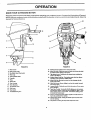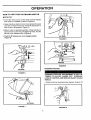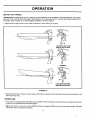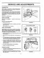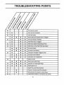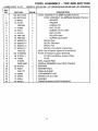
1
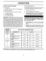
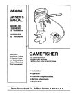
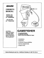
SEARS
OWNER'S
MANUAL
MODEL NO.
225.581508
15" TRANSOM
225.581498
20" TRANSOM
CAUTION:
Read and Follow
all Safety Rules
and Instructions
Before Operating
This Equipment
GAMEFISHER
15 HORSEPOWER
OUTBOARD MOTOR
WITH 6 GALLON REMOTE TANK
• Installation
• Operation
• Customer
Responsibilities
• Service Adjustments
• Repair Parts
Sears Roebuck and Co., Hoffman Estates, IL 60179 U.S.A.
ii
i
iii
i
I
SAFETY RULES
BOATER'S
RESPONSIBILITIES
The operator
(driver) is responsible
for the correct and
safe operation
of the boat and safety of its occupants
and general
public.
It is strongly
recommended
that
each operator
manual before
(driver) read and understand
operating
the outboard.
USING AN OUTBOARD THAT EXCEEDS THE MAXIMUM HORSEPOWER
LIMIT OF A BOAT CAN:
1. CAUSE LOSS OF BOAT CONTROL, 2. PLACE TOO
MUCH WE|GHT AT THE TRANSOM ALTERING THE
DESIGNED
FLOTATION
CHARACTERISTICS
OF
THE BOAT OR 3. CAUSE THE BOAT TO BREAK
APART PARTICULARLY AROUND THE TRANSOM
AREA. OVERPOWERING A BOAT CAN RESULT IN
SERIOUS INJURY, DEATH OR BOAT DAMAGE.
this entire
Be sure at least one additional person on board is
instructed in the basics of starting and operating the
outboard and boat handling in case the driver is unable
to operate the boat.
DO NOT attempt to make repairs or adjustments not
specifically covered in this manual. Should you ever
need technical assistance, please contact your Sears
Service Center.
BEFORE OPERATING YOUR OUTBOARD
Read this manual carefully. Learn how to operate your
outboard properly. If you have any questions, contact
your nearest Sears Store which sells Gamefisher outboard motors.
NEVER OPERATE your motor at full throttle when the
engine is overloaded. This can occur under conditions
when a planing boat is loaded so it does not plane or
when towing another boat.
Safety and operating information that is practiced along
with using good common sense can help prevent personal injury and product damage.
• Some boats are extremely unstable in the water, even
when secured to a dock. Do not stand erect. Stay as
close as possible to centerline of boat while installing
motor.
This manual as well as safety labels posted on the outboard use the following safety alerts to draw your attention to special safety instructions that should be followed.
IMMEDIATE HAZARDS WHICH WILL RESULT
SEVERE PERSONAL INJURY OR DEATH.
• DO NOT store your motor or gasoline where fumes
may reach an open flame and cause a fire.
DRAIN THE GASOLINE
transporting
your motor
vehicle.
IN
HAZARDS OR UNSAFE PRACTICES WHICH COULD
RESULT IN SEVERE PERSONAL INJURY OR DEATH.
I
_
.CAUTION
from your motor before
inside your car or other
GASOLINE AND ITS VAPORS ARE EXTREMELY
FLAMMABLE AND HIGHLY EXPLOSIVE UNDER
CERTAIN CONDITIONS. ALWAYS STOP THE ENGINE AND DO NOT SMOKE OR ALLOW OPEN
FLAMES OR SPARKS IN THE AREA WHILE FILLING
FUEL TANKS.
I
HAZARDS OR UNSAFE PRACTICES WHICH COULD
RESULT IN MINOR INJURY OR PRODUCT OR PROPERTY DAMAGE.
• DO NOT fill the gas tank when the engine is running.
Do not fill the gas tank indoors.
ALWAYS DISCONNECT SPARK PLUG WIRES AND
PLACE WIRES WHERE THEY CANNOT CONTACT
SPARK PLUGS TO PREVENT ACCIDENTAL STARTING WHEN WORKI_IG ON YOUR OUTBOARD
MOTOR.
• REMOVE portable fuel tank from boat when refueling
to prevent spilling fuel in boat. Always mix fuel in a
well ventilated area.
• DO NOT use a motor with a horsepower rating higher
than what is listed (_nthe certification plate on your
boat.
2
CONGRATULATIONS...
PRODUCT
SPECIFICATIONS
You are to be congratulated on your selection of this
Outboard Motor which will give you years of satisfactory
service. Your Gamefisher is the end product of years of
research, engineering and development. It has been
assembled by Craftsmen who take pride in their work.
Engine
This Owner's Guide will help you to receive all the
trouble-free performance built into your motor. READ
THROUGH
THIS MANUAL CAREFULLY
BEFORE
OPERATING THE MOTOR. It contains complete operating instructions and recommendations for the care and
protection of your motor. Following these recommendations and instructions will assure you of years of boating
pleasure.
Engine Type
15 HP
Horsepower Rating
Recommended
Operating Range
Outboarding is a great _port. Always remember, however, that you have friends on the water. Extend to them
the courtesy of thoughtful, safe operation of your motor
and boat and you will increase your own enjoyment.
5500 - 6500 RPM
Two Cycle, Two Cylinder
Alternate Firing
2.25" x 1.94"
57.1 mm x 49.2 mm)
Bore and Stroke
Cubic Inch
Displacement
15.41 Cubic Inches
(252.5 cc)
Water Cooled - Displacement
Type Water Pump
Cooling
I
@ 6000 RPM
Propeller
Right Hand Rotation,
Spline Drive
Spark Plug - Champion
33-328
Spark Plug Gap
Fuel Tank
0.040 in. (1.0 mm)
Remote 6.0 gal. (23 L)
MODEL
NUMBER
Gear Ratio
SERIAL
NUMBER
Weight (approx.)
DATE OF
PURCHASE
Fuel:Oil Ratio
14:22
15" Leg = 62 Ibs. (28.1 Kg)
20" Leg = 64 Ibs. (29.0 Kg)
25:1 Break-In
50:1 Normal
THE MODEL AND SERIAL NUMBERS WILL BE
FOUND ON A DECAL ATTACHED TO THE PORT
STERN BRACKET.
YOU SHOULD RECORD BOTH SERIAL NUMBER
AND DATE OF PURCHASE AND KEEP IN A SAFE
PLACE FOR FUTURE REFERENCE.
CUSTOMER
RESPONSIBILITIES
• Read and observe the safety rules.
• Follow a regular schedule in maintaining, caring for
and using your outboard motor.
• Followthe instructions under"Cus.tomer Responsibilities" and "Storage" sections of this Owner's Manual.
ONE YEAR LIMITED WARRANTY ON GAMEFISHER OUTBOARD MOTOR
For one year from the date of purchase, when this Gamefisher Outboard Motor ismaintained, lubricated and tunedup according to the instructions in the owner's manual, Sears will repair,free of charge, any defect in material and
workmanship.
Ifthis Gamefisher Outboard Motor is used for commercial or rental purposes, this warranty applies for only 90 days
from the date of purchase.
This warranty does not cover:
• Expendable items which become worn during normal use, such as spark plugs, water pump impeller, oil seals,
propellers and tune-ups.
• Repairs necessary because of operator abuse or negligence, including but not limited to strikingan underwater
object and failure to maintain the equipment according to the instructionscontained in the owner's manual.
WARRANTY SERVICE IS AVAILABLE BY RETURNING THE GAMEFISHER OUTBOARD MOTOR TO THE
NEAREST SEARS SERVICE CENTER/DEPARTMENT IN THE UNITED STATES. THIS WARRANTY APPLIES
ONLY WHILE THIS PRODUCT IS IN USE IN THE UNITED STATES.
This warranty gives you specific legal rights, and you may also have other rights which may vary from state to
state.
._
SEARS, ROEBUCK AND CO. Department 817WA, Hoffman Estates, IL 60179
TABLE OF CONTENTS
SAFETY
RULES
MOTOR
SPECIFICATIONS
WARRANTY
MOTOR
.................................
.....................................
ACCESSORIES
INSTALLATION
MOTOR
......................
.........................
.................................
NOMENCLATURE
OPERATION
......................
.................................
2
CUSTOMER
RESPONSIBILITIES
3
SERVICE
3
STORAGE
5
TROUBLESHOOTING
7
REPAIR
8
PARTS
AND
.............
ADJUSTMENTS
.................
..................................
PARTS
POINTS
17-24
25
26-27
..................
................................
ORDERING
28
29
..................
REAR COVER
8-16
INDEX
B
R
I
Before Starting Engine .......
Boat Transom ................
12
Index
........................
4
7
Break-In Procedure ..........
Remove Motor Cover ........
13
Know Your Outboard Motor
Cooling
Customer
..................
System
. .. 8
Responsibilities
L
25
.............
15
....
17
10
Spark Plug ..................
20
Lubrication
22
Start Engine ................
14
Code ............
Steering Friction .............
M
23
E
Exterior Care ................
27
Maintenance
Fuel Pump Filter .............
................
.............
7
Motor Tilt Angle .............
11
Motor Speed (RPM) and
Propeller .................
11
19
12
Recommendations...
17
O
Oil Selection ................
12
Operating
15
Checks ...........
Product
Propeller
Propeller
Checklist
Specifications
16
.....
........
...................
Removal
Submerged Motor
Fresh Water ...............
24
Submerged Motor
Salt Water ................
24
T
...........
Tiller Handle Position ........
10
Throttle Stop ................
25
Troubleshooting Chart .......
28
W
P
Pre-Operation
26
9
Operating In Freezing
Temperatures .............
..........
9
Storage .....................
15
19
G
General
17
Motor ..............
Fuel Ratio Conversion Table .o 12
Selection
Schedule .......
Motor Tilt ....................
F
Gasoline
16
16
Shallow Water Drive Bar .....
Mounting
Fuel Tank Filter
Salt Water Operation ........
Shakedown Checklist ........
6
17
Gear
Housing Lubricant .........
Fuel System
S
Lanyard Stop Switch ..........
Lubrication Schedule ........
D
Draining/Refilling
7
18
K
C
Carburetor
Removing Motor .............
16
3
11
21
Warranty
....................
3
OUTBOARD
MOTOR ACCESSORIES
These accessories
were available when the outboard motor was purchased. They are also available at most Sears retail
outlets, catalog and service centers. Most Sears stores can order repair parts for you, when you provide the model number
of your outboard motor.
SPARK PLUG
FUEL STABILIZER
OUTBOARD
OIL
TC-W3 or TC-W !1
GEAR LUBE
i
PROPELLER
NO. OF
BLADES
DIA.
(IN.)
PITCH
(IN.)
MATERIAL
PART NO.
opuonal - Veryug_ Loads
3
8
9
Aluminum
P-472
Optional- Ught Loads
3
8
8 1/4
Nylon
P-6430
Optional
2
8 1/4
8 1/4
Aluminum
P-286-3
Standard - Average Loads
3
8
9 1/4
Nylon
P-6477
Optional - Average Loads
2
8 1/4
8 3/4
Aluminum
P-70
Optional
3
8 3/8
6
Aluminum
P-715
Optional - Heavy Loads
3
8 1/4
6
Aluminum
P-395
Optional
3
8 1/4
4 1/2
Aluminum
P-396
APPLICATION
- Light Loads
- Medium/Heavy Loads
- Heavy Loads/Sailboat
5
i
ii
GENERAL
LANYARD
STOP
INFORMATION
DISADVANTAGES:
INADVERTENT
ACTIVATION
OF
THE SWITCH
IS ALSO A POSSIBILITY.
THIS COULD
CAUSE ANY, OR ALL, OF THE FOLLOWING
POTENTIALLY HAZARDOUS
SITUATIONS:
1, LOSS OF BALANCE AND FALLING FORWARD
OF
UNSTABLE
BOAT PASSENGERSA PARTICULAR
CONCERN
IN BOW RIDER TYPE BOATS.
2. LOSS OF POWER AND DIRECTIONAL
CONTROL
SWITCH
1 The purpose of the lanyard stop switch is to turn off
the engine ignition
whenever
the operator
(when attached to the lanyard) moves far enough away from the
operator's
position to activate the switch.
2 The lanyard
is a cord usually
between
4 and 5 feet in
length when stretched
out with an element on one end
made to be inserted into the switch and a metal snap on
IN HEAVY SEAS, STRONG
WINDS.
3. LOSS OF CONTROL
WHEN
the other end for attaching to the operator.
It is coiled to
make its at-rest condition
as short as possible so as to
minimize
the likelihood
of the lanyard
entanglement
with nearby objects.
It is made as long as it is in its
stretched
condition
to minimize
the likelihood
of acci-
wrist
or leg) or by tying
Read the Safety Warning following
use or not to use such a switch.
a simple
OR
HIGH
DOCKING.
IN ADDITION,
THERE ARE LIMITATIONS
TO WHAT
THE LANYARD STOP SWITCH CAN DO. THE BOAT
CAN CONTINUE
TO COAST FOR A CONSIDERABLE
DISTANCE
DEPENDING
ON THE VELOCITY
AT
SHUTDOWN
AND THE DEGREE
OF ANY TURN.
HOWEVER,
THE BOAT WILL NOT COMPLETE
A
FULL CIRCLE.
WHILE THE BOAT IS COASTING,
IT
CAN CAUSE INJURY TO ANYONE IN THE BOAT'S
PATH AS SERIOUSLY
AS THE BOAT WOULD WHEN
UNDER POWER.
dental activation
should the operator
choose to move
around
in an area close to the normal operator's
position. If for any reason it is desired to have a shorter
functional
lanyard, this may be accomplished
by using
up length in the way the lanyard and clip are attached to
the operator
(such as wrapping
the lanyard around the
operator's
lanyard.
CURRENT
knot in the
before electing
AS WE CANNOT
POSSIBLY KNOW OF AND ADVISE
THE
BOATING
PUBLIC
OF ALL CONCEIVABLE
BOAT/MOTOR
TYPES AND/OR
POOR OPERATING
to
PRACTICES,
THE FINAL DECISION
OF WHETHER
TO USE A LANYARD STOP SWITCH
RESTS WITH
YOU, THE
OWNER/DRIVER.
WE STRONGLY
RECOMMEND
THAT OTHER OCCUPANTS BE INSTRUCTED
ON PROPER
STARTING
AND OPERATING
PROCEDURES
SHOULD THEY BE
REQUIRED
TO OPERATE
THE OUTBOARD
AND
BOAT IN AN EMERGENCY.
THE FOLLOWING ADVANTAGES AND DISADVANTAGES OF A LANYARD STOP SWITCH SHOULD BE
CONSIDERED BEFORE ELECTING TO USE, OR NOT
TO USE, SUCH A SWITCH.
ADVANTAGES: THE PURPOSE OF A LANYARD STOP
SWITCH IS TO STOP THE ENGINE IGNITION WHENEVER THE OPERATOR (WHEN ATTACHED TO THE
LANYARD) MOVES FAR ENOUGH AWAY FROM THE
OPERATOR'S
POSITION
TO ACTIVATE
THE
SWITCH. THIS WOULD OCCUR IF THE OPERATOR
FALLS OR MOVES WITHIN THE BOAT A SUFFICIENT DISTANCE FROM THE OPERATOR'S POSITION. THIS TYPE OF ACCIDENT IS MOST LIKELY IN
CERTAIN TYPES OF BOATS SUCH AS LOW-SIDED
BASS BOATS, HIGH-PERFORMANCE
BOATS AND
LIGHT, SENSITIVE-HANDLING
FISHING BOATS
OPERATED BY HAND-TILLER. IT IS ALSO LIKELY AS
A RESULT OF POOR OPERATING PRACTICES SUCH
AS SITTING ON THE BACK OF THE SEAT AT PLANING SPEEDS, STANDING AT PLANING SPEEDS,
OPERATING AT HIGH SPEEDS IN SHALLOW OR
OBSTACLE-INFESTED WATERS, RELEASING YOUR
GRIP ON A STEERING WHEEL THAT IS PULLING IN
ONE DIRECTION,
DRINKING AND DRIVING OR
DARING, HIGH-SPEED BOAT MANEUVERS.
6
INSTALLATION
BOATTRANSOM
TRANSOM
OK
OK
TYPE
• Make sure the transom of your boat is designed for
mounting an outboard motor. (Figure 1) The keel
should be tapered from a point about 30" (76.2cm)
ahead of the transom so that it is no more than 1/2"
(1.27cm) thick at the transom.
MOUNTING
NOT SUITABLE
MOTOR
• Mark the vertical
stern of the boat.
• Center
NOT SUITABLE
centerline
(exact middle)
of the
the motor on the transom.
IMPORTANT:
IF THE MOTOR
IS NOT CENTERED
ON
THE TRANSOM,
THE TORQUE
OF THE PROPELLER
WILL TEND TO CAUSE
THE BOAT TO RUN OFF
COURSE AND CREATE HARD STEERING
AND CONTROL.
FIGURE
1
ANTI-CAVITATION
SOME BOATS ARE UNSTABLE IN THE WATER, EVEN
WHEN SECURED TO A DOCK. DO NOT STAND
ERECT. STAY AS CLOSE AS POSSIBLE TO CENTERLINE OF BOAT WHILE INSTALLING MOTOR.
• Raise or lower the motor until the anti-cavitation
plate is 1/2" to 1" below the bottom of the boat.
(Figure 2)
• Tighten stern bracket clamp screws alternately
hand until tight. (Figure 3)
(1.27 crn) -- (2.54
by
FIGURE 2
IMPORTANT: DO NOT USE WRENCH TO TIGHTEN
CLAMP SCREWS.
REMOVING
MOTOR
• To remove the motor from the boat, simply reverse
the installation procedure.
IMPORTANT: WHEN REMOVING, MAINTAIN MOTOR
IN AN UPRIGHT POSITION RESTING ON IT'S SKEG
UNTIL ALL WATER HAS DRAINED
FROM THE
MOTOR LEG.
FIGURE
3
OPERATION
KNOW YOUR OUTBOARD
Read this owner's
MOTOR
manual and safety
rules before
and 5) with your outboard
motor to familiarize
manual for future reference.
operating
yourself
your outboard
with the location
motor.
of various
Compare
the illustrations
controls
and adjustments.
(Figures
4
Save this
14
25
2
OO
15
22
-
10
17
9
18
FIGURE
FIGURE 5
4
1 MotorCover
2 Motor CoverLatch
3 IdleRelief HolesfThermostat
15 StartingDecal: Explains how to startyourmotor.
16 Warm-Up Knob:Puffingthe warm-upknob outrichensthe fuel/
air mixture when startinga coldmotor.
17 "ritltrelease Lever:Rotatingthe tilt release leverenables the
motor to be tiltedup.
18 ShallowWaterDrive Bar:The shallowwater drive bar allows
operatingat lowspeedsin shallowwater.
19 MotorLock Bar:Movingthe motorlockbar changesthe tilt
angle of the motor.
20 GearShift Lever:Allowsshiftingin and out of neutral,forward
and reversegear.
21 LanyardSwitch:Pullingthe cordshutsthe motoroff in an emergencysituation.
22 Twist-GripThrottle:Tumingthe throttleallowsyou to increase
anddecrease speed.It also has twopositiod_:(1) Start - used
whenstartingmotor; and (2) Shift - used beforeshiftingmotor
to forward or reversegear.
23 Primer:Pushingthe primerbuttonsuppliesa smallamountof
fuelto the carburetorfor starting.
24 Starter Rope Handle:Pullingthe starterropeturns the motor
over forstarting.
25 StopButton:Pushingthe stopbuttonstopsthe motor.
4 MotorLeg
5 Anti-CavitationPlate
6 Propeller
7 Skeg
8 WaterInlet
9
10
11.
12
Gear Housing
Stem Brackets
"131t
ReleaseLever
ShiftLever
13 Stop Switch
14 ThrotUe/SteedngArm
8
OPERATION
HOW
TO USE
YOUR
OUTBOARD
MOTOR
MOTOR TILT
• To tilt the motor up out of the water push tilt release
lever down to "Release" position. (Figure 6)
• Grasp handle on back of motor cover and pull forward
until end of travel of tilt stop. Push tilt stop down to
lock motor in tilt position.
(Figure 7)
• Return motor to operating position. Grasp handle on
back of motor cover and pull slightly forward. Pull the
tilt stop up to release motor. (Figure 8)
• Push the tilt release lever up to engage position.
(Figure 9)
TILT STOP
FIGURE 8
ENGAGE
FIGURE 9
STEERING FRICTION
RELEASE
FIGURE 6
STEERING FRICTION ADJUSTMENT
IS NOT INTENDED TO ALLOW "HANDS OFF" STEERING.
LOSS OF CONTROL AND SERIOUS INJURY COULD
RESULT.
• Adjust screw for steering friction desired. (Figure 10)
TILT STOP
FIGURE
7
FIGURE
10
J
ii
i
i
OPERATION
SHALLOW
WATER
DRIVE
BAR
TILLER
The shallow water drive bar allows the motor to operate
at low speeds in shallow water.
• Tilt the motor and lock it in the up position.
Tilt, page 9).
HANDLE
POSITIONS
The motor is equipped
with a throttle
arm that drops
down for convenient
handling during transportation
or
storage.
To drop the handle, lift the arm up slightly,
push and hold the lock lever down. (Figure 13) Drop the
handle until it clears the lock lever. (Figure 14)
(See Motor
• Lift the shallow water drive bar up until it clicks into its
"up" position. (Figure 11)
• Pull the tilt stop up and slowly lower the motor making
sure that the shallow drive bar rests against the motor
lock bar. (Figure 12)
SHALLOW WATER BAR/
/
FIGURE 11
FIGURE 13
f\\
/
\
LOCK BAR
FIGURE
12
FIGURE
10
14
OPERATION
MOTOR
TILT
ANGLE
IMPORTANT:
ADJUST MOTOR TILT ANGLE, IF NECESSARY,
BY CHANGING
THE POSITION
OF THE LOCK
BAR SO THAT THE PROPELLER
SHAFT IS PARALLEL
TO THE SURFACE OF THE WATER WHEN THE BOAT IS
PLANING.
SEE FIGURE 15 TO DETERMINE
CORRECT
MOTOR ANGLE.
• Adjust motor angle if motor is too close to transom or bow will dig in or plow.
LOCK BAR TOO LOW,
MOTOR TOO CLOSE
-2
CORRECT
LOCK BAR TOO HIGH,
MOTOR TOO FAR OUT
FIGURE 15
• Adjust motor angle, if motor is too far away from transom the bow may ride high, the boat may "porpoise,"
the motor may race.
and
PROPELLER
• Your engine is equipped
with a general duty propeller
teristics on a typical boat for this size engine.
which should
• CJ_eck that motor is not over-revving
(RPM too high)
propellers
may be ordered from Sears.
or lugging
11
give you good all around
(RPM too low) at wide
open
Operating
throttle.
charac-
Optional
OPERATION
BEFORE
STARTING
ENGINE
FOR A PROPER
OIL SELECTION
•
Recommended lubricant and gasoline must be properly
mixed or serious damage will result to the engine.
Use NMMA certified TC-W3 or TC-W II outboard oil.
GASOLINE
FUEL MIX
•
Maintain a clean fuel tank.
•
Strain fuel through a fine mesh strainer.
•
Pour one (1) gallon (38.1 cm) of fresh gasoline into an
empty fuel tank. Add proper amount of outboard motor oil. Add balance of gasoline, mix thoroughly.
SELECTION
•
87 pump octane minimum, premium not needed.
•
10% ethanol maximum.
•
3% methanol maximum.
•
Use a major fuel supplier.
IMPORTANT:
Experience
indicates that alcohol
blended fuels (called gasohol or using ethanol or
methanol) can attract moisture which leads to separation and formation of acids during storage. Acidic gas
can damage the fuel system of an engine while in storage. To avoid engine problems, the fuel system should
be emptied before storage for 30 days or longer. Drain
the gas tank, start the engine and let it run until the fuel
lines and carburetor are empty. Use fresh fuel next
season. See Storage Instructions for additional information. Never use engine or carburetor cleaner products in the fuel tank or permanent damage may occur.
USE OR
SERVICE
RATIO
Break-in
25:1
or
TO PREVENT SPILLING FUEL IN BOAT, REMOVE
PORTABLE FUEL TANK WHEN REFUELING. GASOLINE IS HIGHLY FLAMMABLE -- ALWAYS MIX IN
WELL VENTILATED AREA.
•
Observe safety rules - mix fuel in a well ventilated
area (preferably outdoors). Avoid sparks and open
flames.
•
Repeated use of additive compounds
such as
"break-in" oils, "tune-up" compounds, "tonics", "friction reducing" compounds, etc. is not recommended.
FUEL RATIO CONVERSION
GASOLINE QTY.
1 Gallon
3.8 Liters
TABLE
OIL QTY.
1/3 Pint
5.3 oz,
.158 Liters
1 Pint
16 oz.
.473 Liters
3 Gallons (2.5 Imp. Gal.)
11.5 Liters
4% Oil
6 Gallons (5 Imp. Gal.)
5 Liters
2 Pints
32 oz.
.946 Liters
Normal
50:1
1 Gallon
3.8 Liters
1/6 Pint
2.6 oz.
.079 Liters
1/2 Pint
8 oz.
.236 Liters
1 Pint
16 oz.
.473 "Citers
or
2% Oil
3 Gallons (2.5 Imp. Gal.)
11.5 Liters
6 Gallons (5 Imp. Gal.)
23 Liters
NOTE: Regular use of a fuel stabilizer can help avoid fuel problems during short storage periods. Mix stabilizer according
to bottle instructions during each fill up to be sure it will be present during unplanned storage.
12
I
•
II
II
I
OPERATION
BREAK-IN PROCEDURE
I
-- USE 25:1 MIX
,A CAUTION
]
SEVERE DAMAGE TO THE ENGINE CAN RESULT
BY NOT COMPLYING
WITH THE FOLLOWING
BREAK-IN PROCEDURE.
• Mix correct amount of outboard motor oil with each
gallon of gasoline (see gasoline -- oil mixture requirements and fuel ratio conversion table).
• Run engine at moderate speed (approximately 1/2
throttle) for ten minutes. Check operation of the
water pump and cooling system. (Refer to "Checking
Water Pump Operation.")
• Advance to full throttle for a few seconds.
• Return to moderate speed for several minutes.
• Repeat steps 2 and 3 gradually increasing time of full
throttle operation until 5 minutes of full throttle operation has been reached. This break-in operation will
require approximately one (1) hour running time.
• Use the 25:1 gasoline-oil for an additional two (2)
hours before changing to the 50:1 mixture for normal
use.
• AVOID CONTINUOUS
FULL THROTTLE OPERATION FOR AN ADDITIONAL TWO (2) HOURS.
• Your outboard motor may now be operated at any
throttle setting desired using the proper fuel ratio as
specified in the gasoline-oil chart.
DISCONNECT FUEL LINE IF MOTOR IS NOT USED
FOR ANY LENGTH OF TIME. FAILURE TO DO SO
COULD RESULT IN FUEL LEAKAGE INTO THE
BOAT.
• Observe required
structions.
maintenance
and operating
in-
FUEL SYSTEM
FIGURE 16
I
_
CAUTION
1
• Carburetor.
CHECK WITH YOUR SEARS STORE BEFORE USING
ANY FUEL TANK; TO MAKE SURE THE LINE, VENT
AND CHECK VALVE ARE SAFE, AND ARE THE
CORRECT SIZE.
Your motor's carburetor is preset at tll_ factory for
normal operation. If you are operating at varying altitudes or temperature conditions you may need to
readjust the carburetor for best operation. See Carburetor (page 25) in Service and Adjustments section.
• Place fuel tank in a secure level place out of the way.
• Connect fuel line to quick-disconnect
of motor. (Figure 16)
fitting in front
• Slide back sleeve in coupler.
• Place sleeve on bushing and release to lock in place.
13
OPERATION
TO STOP
Retard throttle control to "slow" position, shift engine into
"neutral." Depress "stop" button (E) and hold until motor
stops.
• Shift lever (A) must be in neutral position, when
starting. The motor has a lock out device that prevents the motor from starting when in gear.
• Pull warm-up knob (B) out.
• Push prime bulb (I) onetime.
once.
• Turn twist-grip
Do not prime more than
throttle (C) to start position.
• Pull starter rope (D) out until resistance is felt on rope,
then give the rope a smooth, rapid, even pull. The engine should start on the second or third pull. However,
when starting for the first time, several additional pulls
on the starter may be required in order to initially prime
the engine.
• After engine has started, push warm-up knob in until
engine warms up.
• Turn throttle control to "Shift" position on decal.
• Move shift lever to right for forward operation
the left for reverse operation.
and to
IMPORTANT: ALWAYS SHIFT WITH A QUICK SNAPPING MOTION, NEVER EASE MOTOR INTO GEAR
OR CLUTCH COULD BE DAMAGED.
®
OPERATE SLOWLY IN REVERSE TO AVOID TAKING
WATER INTO THE BOAT OVER THE TRANSOM.
STARTING
FIGURE 17
(WARM)
• Turn twist-grip throttle (C) to start position.
TO START ENGINE
LANYARD
• Pull starter rope (D) out until resistance isfelt on rope,
then give the rope a smooth, rapid, even pull. The engine shouldstart on the second or third pull. However,
when starting for the first time, several additional pulls
on the starter may be required in order to initiallyprime
the engine.
SWITCH
The motor is equipped with a lanyard type switch (F).
Prior to starting, make sure the lanyard cord is attached
to switch. The motor will not start if lanyard is not
connected to switch.
FUEL/FUEL
• After engine has started, push warm-up knob in to
middle position until engine warms up.
LINE
• Turn throttle control to "Shift" position on decal.
• Make sure that fuel tank has a sufficient supply of
properly mixed fuel and that vent screw on fuel tank
filler cap or gauge is open.
• Move shift lever to right for forward operation and to
the left for reverse operation.
• Check that fuel line is securely connected to fitting at
engine (G).
Follow the cold start procedure, starting with step 4.
STARTING (FLOODED)
• Squeeze fuel line prime bulb (H) several times until
bulb becomes firm.
STARTING
[
• If engine is flooded (over primed), make sure warmup button is in, advance throttle control to start position and continue to pull starter rope.
(COLD)
A, CAUTION
DO NOT START YOUR OUTBOARD OUT OF WATER.
THE WATER PUMP HAS A RUBBER IMPELLER
• WJblICH CAN BE DAMAGED BY RUNNING DRY.
14
OPERATION
OPERATING
CHECKS
AND CHECK
COOLING SYSTEM
Cooling water ispicked up on the side ofthe gear housing
just ahead of the propeller, goes through the powerhead,
and then goes out with the exhaust gases.
IMPORTANT: NEVER RUN MOTOR OUT OF THE WATER, AND NEVER RUN MOTOR UNLESS WATER PUMP
IS WORKING NORMALLY OR OVERHEATING AND MOTOR DAMAGE MAY RESULT.
i
• Check that a spray of water is coming out of the idle
relief holes when the motor is idling. (Figure 18)
FIGURE 19
MOTOR
SPEED
(R.RM.)
AND PROPELLER
IMPORTANT:. TO AVOID MOTOR DAMAGE, THE MOTOR MUST BE RUNNING IN THE RIGHT OPERATING
RANGE AND THE PROPELLER MUST BE CORRECT FOR
THE BOAT. (SEE SPECIRCATIONS).
/
•
At wide open throttle check that motor R.P.M. is within
specifications.
•
Ifyour motorseems to be runningwell but is not in the
correct R.RM. range, you may need a propeller with
a different pitch (a smaller pitch increases R.P.M.
while a larger pitch decreases R.RM.). Consult your
Sears Store.
PRE-OPERATION
CHECKLIST
13 Operator knows safe navigation, boating and operating procedures.
FIGURE 18
[]
All needed safety equipment is on board, in good
condition and easy to reach.
Avoid striking underwater objects especially in reverse, since both the motor and the transom may be
damaged. (Figure 19)
[]
Motor isoperating normally. Ifthe motor is hard to start
or is not runningwell, have repairs made before leaving dockside.
If an object
[]
Fuel supply is O.K.
[]
Use only recommended gasoline and oil and use
only the correct mixture.
[]
There are no fuel leaks.
[]
Propeller is not fouled or damaged.
[]
A spare propeller is on board.
[]
The correct anchor and lines are on board.
[]
All anchor and mooring lines are neatly coiled out of
the way.
[]
Recreational equipment and fishing gear is stowed
securely.
OPERATING PRECAUTIONS
is hit, stop and check for damage.
While operating in reverse or in forward, faster than
trolling speed, engage tilt release/reverse lock.
If you operate in very shallow water, you may plug the
water inlet with mud or debris which will cause your
motor to overheat.
Avoid shallow
water. If you must operate in shallow
water or in an area where there are known obstructions, use shallow water driver" bar (page 10).
If while operating
your boat the propeller
comes in
contact with fishing line, stop motor. Visually inspect
and remove any line that is wrapped around prop. As
soon as possible,
remove
engine from
water and
check gear housing for water which would indicate a
da_naged seal.
Ip
F__] Bilge is pumped and there are no water leaks.
15
[]
Passengers are safely on board.
[]
The area is clear for operation. Operator is aware of
other boats, skiers, divers, swimmers, etc.
OPERATION
SHAKEDOWN
IMPORTANT: IF THE MOTOR IS TILTED OUT OF THE
WATER, WATER REMAINING IN THE COOLING SYSTEM
AND GEAR HOUSING MAY FREEZE AND CAUSE PARTS
TO BREAK.
CHECKLIST
[]
Operator has read and understood the entire operator's manual.
[]
Operator has carried out pre-operation checklist.
[]
Operate cautiously and get to know how your boat
handles.
[]
If the motor is new, follow all break-in procedures.
[]
Follow all operating procedures.
[]
Check tightness of mounting clamps.
[]
Adjust motor angle if necessary.
[]
Adjust idle if necessary.
•
Always tilt the motor out of the water when not in use.
[]
Adjust carburetor if necessary.
•
[]
Check that propeller is correct for boat.
From time to time run the motor in fresh water to flush
out salt deposits.
•
Wash motor down with fresh water and soap; rinse.
Apply a marine-type wax to protect the finish.
•
Periodically remove propeller and lubricate propeller
shaft.
•
Replace water pump impeller every year. Apply antiseize compound to the driveshaft/crankshaft spline.
•
SALT WATER OPERATION
Although all motor parts that contact water have been
chemically treated to resist salt water corrosion, you
should take some special steps after runningyour motor
in salt water.
OPERATING
IN FREEZING
TEMPERATURES
•
i
Do not start a motor that might be frozen.
When using the motor in freezing or near freezing temperatures, keep the gear housing in the water. When
launching the boat/motor in near freezing"temperatures, let the rig soak for 20 to 30 minutes before starting to allow water in the water pick-up, water pump,
or water tube to thaw.
,A CAUTION
IF OUTBOARD IS STORED TILTED UP IN FREEZING
TEMPERATURE, TRAPPED COOLING WATER OR
RAIN WATER THAT MAY HAVE ENTERED THE
EXHAUST OUTLET IN THE GEAR CASE COULD
FREEZE AND CAUSE DAMAGE TO THE OUTBOARD.
16
CUSTOMER
'
MAINTENANCE
SCHEDULE/
RESPONSIBILITIES
/
/
._ /.o,.
F.,,._ates
as.o,,
/
_/_
._j/_o_.#
I/' _;_lt._f
_"._tl ..:#I/'&"'!
.&_'!
complete regular service
/
Check for loose fasteners
Check fuel tank filter
•
Check spark plug
•
Check propeller condition
•
Chart
Shift Linkage
Carb Linkage
•
•
Swivel Bracket
Clamp Screws
•
•
Propeller Shaft
•
•
Gear Housing
Check level
•
Replace grease
The warranty
DATES
•
•
GENERAL
SERVICE
/
._o-
Check fuel pump filter
Lubrication
/
/
•
RECOMMENDATIONS
on this outboard
motor
does
not cover
USING A REPLACEMENT
PART THAT IS INFERIOR
TO THE ORIGINAL
PART COULD RESULT IN PERSONAL INJURY, DEATH OR PRODUCT
FAILURE.
items that have been subjected
to operator
abuse or
negligence.
To receive
full value from the warranty,
operator
must maintain
the outboard
as instructed
in
this manual.
Some adjustments will need to be made periodically
properly maintain your unit.
• As needed, but at least annually you should replace
the spark plugs, fuel filters, and water pump impeller.
to
• Routinely
All adjustments in the Service and Adjustments section
of this manual should be checked at least once each
season.
• Follow
check all fasteners for tightness.
the Lubrication
Schedule
• Check
gear housing
lube
Replace every one hundred
(6) months.
NEGLECTED
INSPECTION
AND
MAINTENANCE
SERVICE
OF YOUR OUTBOARD
OR ATTEMPTING
TO PERFORM
MAINTENANCE
OR REPAIR ON YOUR
OUTBOARD
IF YOU ARE NOT FAMILIAR WITH THE
CORRECT
SERVICE
AND SAFETY
PROCEDURES
COULD
CAUSE
PERSGNAL
INJURY,
DEATH
OR
PRODUCT
FAILURE.
17
on page 22.
every thirty
(100) hours
(30) hours.
of use or six
CUSTOMER
TO REMOVE
MOTOR
RESPONSIBILITIES
COVER
PUSH
DOWN
DO NOT REMOVE OR INSTALL COVER WHILE
MOTOR IS RUNNING. THE COVER PROTECTS YOU
FROM MOVING PARTS, WHICH COULD CATCH
HANDS, HAIR OR CLOTHING AND CAUSE SERIOUS
INJURY.
• Push down hard on cover and turn cover release lever
on rear of motor. (Figure 20)
REAR
• Lift cover up in rear and move cover to front to free
it from cover retainer. Lift cover up and off.
TO INSTALL
MOTOR
COVER
FIGURE 20
• Place cover retainer into slot in front of motor cover.
(Figure 21)
• Push cover back slightly over seal.
• Push down and turn release lever to lock cover in
place.
/
COVER
RETAINER
DOWN
_
P
FIGURE 21
18
CUSTOMER
FUEL
PUMP
RESPONSIBILITIES
FILTER
PUMP
• Remove motor cover.
COVER
• Remove fuel line from pump. (Figure 22)
• Remove filter/fitting
from pump cover.
NOTE: FILTER IS PART OF THE FUEL FITTING.
• Clean or replace filter.
• Reinstall filter/fitting
with clamp.
and connect fuel line and secure
AVOID SPILLING FUEL AND KEEP ALL SOURCES
OF HEAT, FLAME AND SPARKS AWAY WHEN DISCONNECTING,
HANDLING
OR STORING
FUEL
SYSTEM COMPONENTS.
FUEL
TANK
FIGURE
22
FIGURE
23
FILTER
•
Disconnect fuel line from motor.
•
Remove fuel connector assembly from fuel tank.
•
Remove fuel filter from bottom of assembly (Figure
23).
•
Wash filter in clean solvent.
•
Replace filter if rusted, corroded or damaged.
•
Reinstall fuel connector assembly and reconnect fuel
line.
19
CUSTOMER
SPARK
RESPONSIBILITIES
PLUG
•
Remove motor cover.
•
Disconnect spark plug lead by twisting slightly and
pulling (Figure 24).
FIGURE 24
•
Remove, clean and inspect spark plug. (Figure 25).
•
Replace plug if tip of insulator is rough, cracked, broken or blistered, or if the electrodes are eroded.
FIGURE 25
•
Gap plug to .040 in. (1.0 mm) (Figure 26).
•
Check spark plug gasket and carefully clean spark plug
seat on cylinder head.
.040 in.
(1.0mm)
IMPORTANT: DO NOT OVERTIGHTEN SPARK PLUG OR
DAMAGE TO CYLINDER HEAD MAY RESULT.
•
Install plug finger tight, and then tighten about 1/4 turn or
torque to 120 - 180 lb. in. (13.6 - 20.3 N-m).
•
Install spark plug lead.
FIGURE 26
20
CUSTOMER
COOLING
•
RESPONSIBILITIES
SYSTEM
If motor overheats, have your Sears Service Center
check the water pump for damage.
PROPELLER
Your motor comes with a propeller designed for good
all-around performance on most boats. Check that
motor is not over-rewing (R.RM. too high) or lugging
(R.RM. too low) at wide open throttle.
IMPORTANT: IF THE PROPELLER IS CHANGED FOR
SPECIAI_ USE OR CONDmONS, BE SURE THAT R.RM.
STAYS WITHIN SPECIFICATIONS, OR SERIOUS MOTOR
DAMAGE COULD RESULT. SEE YOUR SEARS SERVICE
CENTER FOR HELP.
• Unusual or extreme vibration may be caused by a
propeller that is bent, unbalanced, badly nicked,
broken or clogged with weeds.
FIGURE 28
• Inspect and clean, repair or replace propeller when
this type of vibration happens.
SHIFT INTO NEUTRAL GEAR POSITION AND DISCONNECT SPARK PLUG WIRES TO PREVENT ACCIDENTAL STARTING AND SERIOUS INJURY WHILE
SERVICING PROPELLER.
•
Remove cotter pin (Figure 27) and pull off propeller nut
(Figure 28).
•
Remove thrust pin from hub (Figure 29).
•
Pull propeller straight back and off propeller shaft. If propeller is frozen to shaft, tap propeller gently with a block
of wood (Figure 30).
•
Lubricate propeller shaft liberally (see
Chart).
•
Lubrication
FIGURE 29
Reinstall propellerthrust pin, propeller nut and cotter pin.
FIGURE
27
FIGURE
21
30
i
CUSTOMER
I
i
II
RESPONSIBILITIES
LUBRICATION
NOTE: Bold letters indicate type of lubrication as specified below,
CARBLINKAGE
SHIFT LINKAGE
CLAMP
SCREWS
SHIFT LINKAGE
WARM UP BUTTON
LINKAGE
SWIVELBRACKET
&
GREASEFITTING
GEAR HOUSING
PROPELLER SHAFT
FIGURE
LUBRICATION
A. Sears Outboard
Gear Lube. (If not available,
31
CODE
use non-corrosive,
B. Waterproo!
Marine Grease, All Purpose Auto Chassis Lubricant
above lubricants are not available, use SAE #40 motor oil.
C. "Anti-Seize"
Lubricant.
22
EP 90 outboard
or"Rykon"
gear lube.)
#2. For temporary
lubrication
when
CUSTOMER
DRAINING
•
GEAR
HOUSING
RESPONSIBILITIES
LUBRICANT
With motor upright, remove the vent screw and the fill
and drain screw. Allow lubricant to drain completely
(Figure 32).
IMPORTANT: WHEN ADDING OR CHANGING LUBRICANT, INSPECT FOR WATER CONTAMINATION.
TO INSPECT, LOOSEN (DO NOT REMOVE) GEAR
HOUSING
DRAIN PLUG SCREW AND ALLOW A
SMALL AMOUNT OF LUBRICANT
TO DRAIN. IF
WATER-IS PRESENT IT WILL DRAIN PRIOR TO THE
ACTUAL LUBRICANT. SHOULD WATER BE PRESENT, TAKE YOUR ENGINE TO YOUR SEARS SERVICE
CENTER.
_]==0
FILL AND DRAIN SCREW
VENT
FIGURE
SCREW
33
VENT SCREW
FILL AND DRAIN SCREW
FIGURE 32
ADDING/REFILLING
LUBRICANT
•
Remove fill and drain screw and washer, an insert
nozzle of tube into hole (Figure 33).
•
Remove vent screw and washer (Figure 34).
•
Add lube until it appears at vent hole (Figure 35).
•
Reinstall vent screw and washer, and tighten securely.
•
Remove nozzle, reinstall filland drain screw and washer, and tighten securely.
•
Remove vent screw and allow motorto stand upright for
at least one-half (1/2) hour.
•
Recheck lube level. Add lube if necessary to bring level
up to top hole.
•
Reinstall vent screw and washer. Tighten securely.
FIGURE 34
FIGURE
23
35
i
i
CUSTOMER
SPECIAL
RESPONSIBILITIES
SITUATIONS
SUBMERGED
• If motor
damaged
follows:
i
MOTOR
If motor starts, run for at least an hour until parts are
thoroughly
warmed up and water has evaporated
from
moving parts inside.
FRESH WATER
is recovered
within a few hours, and is not
and does not have dirt inside, try to start as
SUBMERGED
MOTOR
SALT WATER
• Drain fuel lines and carburetor.
IMPORTANT: DO NOT ATTEMPT TO START MOTOR
UNTIL ALL ELECTRICAL PARTS ARE CLEANED AND
DRIED.
• Remove spark plugs and turn motor over several
times by pulling starter rope to force water from
the crankcase and cylinder.
• Immediately flush away all salt water, both inside and
out, with clean fresh water.
• Dry off and install spark plugs and dry off ignition
components.
• Follow all steps for fresh water submersion
previously.
• If motor will not start, protect
ignition dryer and conditioner
parts with a thick coat of oil.
• If fuel tank was submerged,
drain all fuel from tank
and flush with fresh fuel until all water is removed.
• Try starting
motor,
using fresh
all electrical
and cover
"
outlined
parts with
all external
fuel mixture.
• Immediately take motor to a Sears Service Center for
servicing.
24
SERVICE
AND ADJUSTMENTS
CARBURETOR
NOTE: Adjust the carburetor for better starting and low
speed operation when there are changes in temperature,
humidity or barometric pressure.
The high speed system, which meters fuel from high idle
to wide open throttle, is factory equipped with a jet that is
not adjustable. The jet can be replaced with a jet for high
altitude operation. Consult your Sears Service Center for
installation.
Adjust idle as outlined below:
INITIAL
SETTING
NOTE: Do not overtighten damaged.
needle and seat may be
BEFORE STARTING MOTOR:
FIGURE 36
•
Remove motor cover.
•
Tum idle adjustment needle in, clockwise, until it seats
lightly (Figure 36).
•
Back needle out one (1) full turn.
IDLE ADJUSTMENT
FINAL ADJUSTMENT
RICH
SCREW
LEAN
HALFWAY
IMPORTANT:. DO NOT ADJUST LEANER THAN NECESSARY TO OBTAIN sMooTH IDUNG. IT IS BETI'ER TO
HAVE IDLE SET A U'rTLE RICH THAN TOO LEAN. A LEAN
sE-n'ING CAN CAUSE MOTOR DAMAGE.
With boat tied securely to dock, start motor and run until
fully warmed up.
Set controls to lowest reliable idle in neutral gear position.
3
4
FIGURE 37
Tum idle adjustment needle slowly open, counterclockwise, until motor loses power and begins to roll due to
an over-rich mixture. Note this position (Figure 37).
Slowly tum needle closed, clockwise, until motor runs
smoothly and begins to pick up speed. Continue turning
clockwise until motor pops or stalls due to lean mixture.
Note this position.
Set needle halfway between the two positions.
Repeat, as needed for fine tuning.
THROTTLE
STOP
•
Your motor isequipped with a throttle stop which can be
adjusted for correct idle speed.
o
If needed tum the throttle stop adjusting screw (A) to obtt_n approximately an 800 RPM idle when in neutral
gear (Figure 38).
25
FIGURE 38
5
i
i
i
i
STORAGE
PREPARATION
FOR
STORAGE
II
©
• We recommend
that your Sears Service Center prepare your motor for storage during the off season or
for long periods of time.
• The Service Center has the latest tools, materials and
information and can also carry out maintenance as
required.
• If your motor cannot be taken to your Sears Service
Center, follow the steps below to prevent rust and
damage from freezing temperatures.
IMPORTANT: IF GASOLINE MUST BE LEFT IN TANK,
USE A GASOLINE STABILIZER.
MIX STABILIZER
ACCORDING TO BOTTLE INSTRUCTIONS
DURING
EACH TANK FILL UP TO ASSURE THAT IT WILL BE
PRESENT DURING EACH STORAGE INTERVAL.
FIGURE 39
• Gasoline stabilizer helps prevent gum deposits from
forming in essential fuel system parts such as the
carburetor, fuel filter, fuel hose, or tank during storage. Also, experience indicates that alcohol blended
fuels (called gasohol or using ethanol methanol) can
attract moisturewhich leads to separation and formation of acids during storage. Acidic gas can damage
the fuel system of an engine while in storage.
• To avoid engine problems, the fuel system should be
emptied before storage of 30 days or longer. Follow
these instructions.
AVOID SPILLING FUEL AND KEEP ALL SOURCES OF
HEAT, FLAME AND SPARKS AWAY WHEN DISCONNECTING, HANDLING OR STORING FUEL SYSTEM
COMPONENTS.
•
FIGURE 40
Remove motor cover.
With motor mounted on boat and in fresh water, run the
motor until it is thoroughly warmed up.
)
Place shift lever in neutral and run motor at fast idle
(Figure 39).
Disconnect fuel line from bushing on motor (Figure 40).
O
When motor begins to stall, rapidly inject a rust preventative oil into the carburetor air intake for ten (10) to
twenty (20) seconds until motor stops (Figure 41).
This protects the crankcase with a coating of oil.
•
Remove boat and outboard from water.
FIGURE 41
26
STORAGE
•
Remove spark plug and put an ounce or two of outboard oil into spark plug hole (Figure 42).
•
Reinstall spark plug.
•
Pull starter rope several times to lubricate piston, rings
and cylinder walls and to remove water from cooling
system.
•
Lubricate all parts, as outlined in Lubrication.
•
Drain and refill gear housing, as outlined in Lubrication.
•
Lubricate and service propeller, as outlined in Maintenance.
•
Reinstall motor cover.
EXTERIOR
•
CARE
Your outboard isprotected with a durable enamel finish.
To keep its appearance, wash and wax often using marine cleaners and waxes (Figure 43).
PREPARATION
FOR
USE AFTER
FIGURE 42
STORAGE
• We recommend that your Sears Service Center prepare your motor for use after storage. The Service
Center has the latest tools, materials and information.
• They can also perform maintenance as required by
warranty, test-run your motor and perform tune-up
and adjustments needed for good operation. If your
motor cannot be returned to your Sears Service Center, do the following steps:
• Remove spark plug and clean or replace, as outlined under Maintenance.
• Lubricate all parts, as outlined under Lubrication.
• Check lubricant in gear housing, as outlined under
Lubrication.
• Service exterior of motor, as outlined under Exterior Care.
FIGURE 43
• Drain fuel tank and use a fresh fuel mixture.
27
i
i
TROUBLESHOOTING
POINTS
FL'el Line Air Locked
Fuel Une Not Connected
i
Fuel Tank Empty
Recirculating Fuel System Dirty or Clogged
Fuel Line Kinked or Pinched
Fuel Filters Dirty or Clogged
i
Vent Screw Gasket Obstructing Air Flow
Vent Screw on Fuel Tank Filler Cap Closed
•
i
•
•
Air Leak in Motor
•
•
Air Leak in Fuel System
•
•
Carburetor Passages Clogged or Dirty
i
•
i
i
Incorrect Fuel-Oil Mixture.
==
Carburetor Out of Adjustment
Motor Flooded
•
•
•
•
Wrong Type Spark Plugs
Defective or Fouled Spark Plugs
Weak Ignition Coil
Spark Plug Lead Wires Switched
Frayed or Cracked Lead Wire Insulation
Disconnected, Grounded or Loose Wiring
Q
Lanyard Not Installed on Emergency Stop Switch
28
" INUI"_:
COWL ASSEMBLY - TOP AND BO-I-rOM ....................................
IGNITION SYSTEM .......................................................
SHIFT LINKAGE ..........................................................
FUEL AND RECIRCULATION
SYSTEM
.....................................
CARBURETOR
...........................................................
STARTER ASSEMBLY
....................................................
CRANKSHAFT AND PISTON ...............................................
CYLINDER BLOCK
.......................................................
STEERING HANDLE/TWIST
GRIP THROTTLE
...............................
SWIVEL BRACKET AND DRIVESHAFT
HOUSING
...........................
CLAMP BRACKETS .......................................................
THERMOSTAT
...........................................................
GEAR HOUSING
.........................................................
FUEL TANK AND LINE ....................................................
MISCELLANEOUS
PARTS .................................................
OPT = optional
NOTE: indented
assembly.
AR = As Required
description
N.S.S. = Not Sold Seperate
indicate that these parts are included in preceding
THESE PARTS BOOKS/FICHE
CARDS ARE COPYRIGHTED
AND MAY NOT BE
DISTRIBUTED OR REPRODUCED
IN ANY OTHER FORMAT.
29
30
32
34
36
38
40
42
44
46
48
50
51
52
54
55
L;UWL/_:3_t:IVlI_LY
GAMEFISHER
-
15 H.P.
I UP
MODELS:
AND
225.581508
BOTTOM
- 15" TRANSOM
and 225.581498
- 20" TRANSOM
PORT SiDE )
(STARBOARD
SIDE
11
1920
23
13
\
12
25
30
COWL
GAMEFISHER
15 H.P.
MODELS:
PART NO.
ASSEMBLY
225.581508
- TOP AND
- 15" TRANSOM
and 225.581498
100- 820i54A6
1
1
100- 820154A2
1
COWL ASSEMBLY-Top
COWL ASSEMBLY-Top
(Witl_ Decals)
2
12- 89302
4
WASHER
2A
12- F8143
4
WASHER
1
HANDLE-Tilt
F681269
(Without
4
11- F7009
4
NUT (10-24)
5
10- F2211
4
SCREW (10-24 x 5/8")
7
11-814101
1
8
23- F681759
1
NUT (1/4-20)
ROLLER-Latch
9
10- F681026
1
SCREW-Latch
10
37- 826342-16
1
DECAL-Rear
11
37- 826342-14
1
DECAL-Starboard
11
37- 826342-15
1
DECAL-Port
12
37- 826342-17
1
DECAL-Front-Starter
13
14
F392756
100- 819280A2
1
SEAL-Top
1
PLATE KIT-Bottom
15
38- 819281 --1
1
16
19- 73336
1
1
SEAL-Support
18
FA681469T
1
Roller
Instructions
Support Plate
Plate
19
23- 812707
2
HANDLE ASSEMBLY-Cowl
BUSHING
20
13- F2047
1
WASHER-Wave
1
CAM-Latch
Latch (Painted)
Shaft
22
13- 26992
1
LOCKWASHER
23
10- 28635
1
24
12- 35044
1
SCREW (1/4-20 x 5/8")
WASHER
25
90- 830211
1
OWNERS
I
Decals)
Support (Painted)
PLATE-Front-Bottom
PLUG
819486
F481777
(Painted)
of Bottom Support (Cut as Req'd)
17
21
-20" TRANSOM
DESCRIPTION
QUAN.
!
3
BOTTOM
(1/4")
MANUAL]PARTS
31
MANUAL
(Painted)
"
IGNITION
SYSTEM
GAMEFISHER
15 H.P.
22
MODELS:
225.581508
- 15" TRANSOM
16
8
It
.
32
and 225.581498
-20" TRANSOM
IGNITION
GAMEFISHER
REE
NO.
1
15 H.P.
PART NO.
F681091
MODELS:
225.581508
- 15" TRANSOM
QUAN.
and 225.581498
DESCRIPTION
1
NUT-Flywheel
2
200- 824380T1
1
FLYWHEEL
4
87- 824440A9
1
SWITCH
824466A3
1
COVER ASSEMBLY-Stop
824915
1
BEZEL-Stop
5
5A
6
87- 826214A1
1
7
819399A1
1
8
84- 819379A7
1
9
10
300- 826692T
819156T
1
2
(Painted)
ASSEMBLY-Stop
Switch Cover
SWITCH ASSEMBLY-Emergency
LANYARD ASSEMBLY
Stop
826691
1
MODULE-Ignition
CAM-Throttle
12
FKl123
2
BOOT KIT-Spark Plug
12
85- 818751
13
33- 328
2
13
33-814
OPT
14
28- F458498-1
1
KEY-Crankshaft/Flywheel
15
22- F681188
1
NUT-Stop
16
10- 824353
6
SCREW
(8-32 x 3/4")-Ignition
17
10- 824352
1
SCREW
(10-24 x 3/8")-Ground
1
CABLE TIE (4")
18
56762
COVER-Spark
(Cut Wire as Req'd)
Plug (RFI)
SPARK PLUG (CHAMPION
5
20
84- 60466A16
1
SCREW (10-24 x 1/2")-Stator
WIRE ASSEMBLY-Ground
21
10- 824358
1
SCREW
1
MARKER
2
CABLE TIE (8'_
54- 816311
# RL82YC)
Switch Sleeve
10- 824358
20117A1
# L82YC)
SPARK PLUG (RFI) (CHAMPION
19
22
Stop
HARNESS ASSEMBLY-Engine
PLATE-Stator
11
OPT
Switch
Module
Plate
(10-24 x 1/2")-Ground
SET-Ignition
33
Module Cable
SYSTEM
- 20" TRANSOM
SHIFT LINKAGE
GAMEFISHER
15 H.P.
MODELS:
225.581508
5
17
- 15" TRANSOM
and 225.581498
6
I"__
7
9.._.>
8
10
13
34
- 20" TRANSOM
SHIFT LINKAGE
GAMEFISHER
REF.
NO.
15 H.E
PART NO.
MODELS:
225.581508
- 15" TRANSOM
and 225.581498
DESCRIPTION
QUAN.
1
F681490
1
2
F681003-1
1
STOP-Starter Pulley Interlock
ARM-Starter Interlock
3
12- F8143
1
WASHER
4
10- 48408
1
5
24- F681424
1
SCREW (10-16 x 1/2")
SPRING-Interlock
Lever
6
16- F681134
1A
STUD-Interlock
7
16- 826590
8
824357
1A
1
STUD-(1/4-20 x 1.69") W/Dri Loc-Neutral
LEVER-Neutral
Interlock
9
11-814101
1
Lever
10
F681531-1
1
NUT (1/4-20)
ROD-Interlock
!1
816514
2
BEARING
!2
10- 819625
1
SCREW-Shoulder
13
F286615
1
14
824826
1
ROD-Gear Shift-Upper
SHAFT-Gear Shift Handle
15
F681263-1
1
LINK-Starter
16
F681742
1
LEVER-Intermediate
2
NUT (10-32)
LINK-Shift Lever
17
18
19
20
11-20110
825402
13- 26996
F286685
1
1
1
1
STUD-Rod
22
13- F8058
1
LOCKWASHER
1
1
LEVER-Gear
PIN-Roll
1
PIN-Gear
24
25
17- 31656
F286871
Interlock
LOCKWASHER
(#10)
CONNECTOR-Gear
Shift Rod
16- F98273
819508T
End Connector
(#10 Internal)
Shift (Painted)
Shift Lever
26
23- 26841
4
BUSHING
27
16- F286134
1
STUD-Gear
28
17- 25905
2
PIN-Roll
Shift Lever
29
819626T
1
30
820367--1
1
HANDLE-Gear Shift (Painted)
LEVER-Shift Handle Shaft
1
WASHER-Bowed
31
13- F8048
Interlock
Interlock
21
23
- 20" TRANSOM
• = Contents
35
of Short Block Assy
800-819553A14
Pivot
FUEL AND RECIRCULATION
GAMEFISHER
15 H.P.
MODELS:
SYSTEM
225.581508
- 15" TRANSOM
and 225.581498
31 32
30
25
23
6
2
20
4
,TO CARB
;IDE ELBOW
16
14
<"
.i
i/
10
11
\
TO CARB_
34
TOP FITTING
13
12
36
- 20" TRANSOM
I"UIF_.L/-_I_IIU
GAMEFISHER
REF.
NO.
15 H.P.
PART NO.
MODELS:
225.581508
I1F-..LplII_,UL./-_I
- 15" TRANSOM
34- FA7i 5158
1
2
10- 28430
8
SCREW
3
13- F1704
8
LOCKWASHER
4
34- F715161
4
STOP-Reed
5
34- F31160-2
4
REED
• 27- F286159-1
7
• 27- F715168
8
FA715167
1A
and 225.581498
(6-32 x 1/4")
GASKET-Reed
(#6 Internal)
Plate
1
GASKET-Manifold
1
MANIFOLD
KIT-Carburetor
(Painted)
2
10
32- F40253-1
1
11
27- F715906
14
12
11- 20890
2
NUT (1/4-20)
13
10- 28668
6
14
54- 827255
4
SCREW
CLAMP
15
32- F40253-1
2
16
22- F197767-2
1
HOSE-Fuel (8-1/4") (13.38") (Cut as Req'd)
BUSHING-Fuel
17
22- F901811
1
FILTER-Fuel
COVER ASSEMBLY-Cylinder
STUD (1/4-20 x .91') With Dri Loc
HOSE-Primer
Bulb to Carb (5-3/4')
GASKET-Carburetor
Pump
FA429471
1
19
F429811
2
SCREEN
VALVE KIT
21- 817741A1
2
21
54- F286772-1
1
22
23
• 27- 825188
10- F1069
1A
GASKET-Cylinder
3
SCREW
Drain Cover
(10-24 x 1-1/16")
819993T1
1
COVER-Fuel
25
27- F24748-2
1
GASKET-Fuel
1
PLATE ASSEMBLY-Fuel
WASHER
F2A24757
Pump (Painted)
Pump
27
12- 18552
2
28
34- F18160-3
2
REED
29
10- F1286
2
SCREW
3O
27- 818043A1
1A
GASKET/DIAPHRAGM
31
820116--2
1A
COVER-Transfer
1A
GASKET-Transfer
32
• 27-825183
Drain (Painted)
CLAMP
24
26
(Cut as Req'd)
(1/4-20 x 7/8")
18
20
- 20" TRANSOM
PLATE ASSEMBLY-Reed
16- 826622
9
_._ ; _,_ t _-tvt
DESCRIPTION
QUAN.
1
6
IUI_II
33
F681954-1
1
COVER-Primer
34
F681046
1
BULB-Primer
Pump
(4-40 x 3/16")
SET
Port
Port Cover
Bulb
35
10- 98254
4A
SCREW
(1/4-20 x 5/8")
36
10- F1922
4
SCREW
(1/4-20 x 5/8")
A = Contents of Short Block Assy 800-819553A14
• = Contents of Short Block Gasket Set FG1035
z_ = Contents
37
of Carburetor
Gasket Set FK10352
CARBURETOR
GAMEFISHER
15 H.P.
MODELS:
225.581508
- 15" TRANSOM
and 225.581498
- 20" TRANSOM
20
29
14
21
24
22
\
2
_5
31-o
18
17
33
I
13
19
10
34
3O
38
%J,I"_,FIII;_,,,I
GAMEFISHER
REF.
NO.
1
2
3
4
5
6
7
8
9
10
11
12
13
14
15
16
17
18
18
18
18
19
20
21
22
23
24
25
26
27
28
29
30
31
32
33
34
15 H.P.
MODELS:
PART NO.
QUAN.
1300- F715061-1
19- FO16128
19- FO10588
FO4784
FO8805
F10343
F10344
10- F10345
1
27139927-
241395139513991399-
F10346
FO13944
FO15366
FO 15623
5128
FO2510
F10347
F10268
27160
F10265
6030
6029
4215
4216
FO 15722
820578
F10273
F10275
F10290
F10241
F10242
F10338
F10349
24- F10350
F10351
FK10352
FK10353
F681677
F286547
819348
F341384
23- F197319
lo
40
1
1
1
1
2o
1
lo
1
loz_
1
2oz_
1
1
lo
lo
1
OPT.
OPT.
OPT.
1
1
1
1
1
2
1
1
1
lo
1
1
1
1
1
1
1
1
225.581508
- 15" TRANSOM
and 225.581498
hi,.,,,
ii _b,,,_
rl
- 20" TRANSOM
DESCRIPTION
CARBURETOR
(FO-1B)
PLUG-By Pass Chamber
PLUG-Body Channel Plug
BALL-Choke Friction
SPRING
SHAFT-Choke
SHUTTER-Choke
SCREW-Shutter
FLOAT-Fuel Bowl
PIN-Float
BOWL-Fuel
GASKET-Fuel Bowl
SCREW-Fuel Bowl
GASKET-Fuel Bowl Screw
ELBOW
SCREW-Idle Mixture
SPRING-Idle Mixture Screw
NEEDLE-Inlet
JET-Main (.070)
JET-Main (.068)
JET-Main (.066)
JET-Main (.064)
NOZZLE-Main
(0- 2500')
(2500- 5000')
(5000- 7500')
(7500- 10000')
JET-Idle Air Bleed (.048)
JET-Throttle (.047)
SCREW-Throttle Jet Sealing
LINKAGE-Throttle
CLIP-Throttle Linkage Shaft
WASHER-Throttle
Linkage Shaft
LINK-Throttle
SHAFT-Throttle
SPRING-Throttle
Shaft
SHUTTER-Throttle
GASKET SET-Carburetor
(a = Contents of Gasket Set)
REPAIR KIT-Carburetor
(o = Contents of Repair Kit)
INSERT-Choke
Knob
KNOB-Choke
ROD-Choke
RETAINER-Choke
Rod
BUSHING-Choke
Rod
39
STARTER ASSEMBLY
GAMEFISHER
15 H.P.
MODELS: 225.581508
- 15" TRANSOM
and 225.581498
23
13
16
/
i
i
J
i
i
/
t
j
/
K
21
13
40
- 20" TRANSOM
V
GAMEFISHER
REF.
NO.
1
2
3
4
15 H.P.
PART NO.
826693
10- 90192
826559A1
53- 42689
MODELS:
225.581508
- 15" TRANSOM
1
HOUSING-Starter
2
SCREW (1/4-20 x 3/4")
1
BRACKET
1
RING-Retaining
1
INSERT-Starting
6
23- F681405
2
INSERT-Starter
7
11-814101
1
NUT (1/4-20)
8
10- F1922
4
9
24- F681970
1
SCREW (1/4-20 x 5/8")
SPRING-Starter
Rewind
10
42034A2
1
PULLEY ASSEMBLY-Starter
Housing
19- 817362
1
PLUG
12
26- F681579
1
SEAL-Pulley
13
F681232
1
ROPE (64/67")
14
F681592
3
RETAINER-Starter
3
Rope
Pulley
16
FA681630T
1
17
F681090
1
PLATE-Handle
2
SCREW
1
2
FASTENER-Handle
SCREW-Shoulder
19
20
F681874-1
10- 819625
Support
(1/4-14 x 1/2'_
Support Plate
21
F681132
1
HANDLE-Starter
22
F681817
1
23
FA609853
1
RETAINER-Starter
Rope
DECAL KIT-Shift to Neutral
24
10- F2030
1
Rope
25
830265
1
SCREW (1/4-20 x 1-1/4")
RETAINER-Throttle
Cable
26
10- 826676
1
SCREW
27
28
26852
23- 830196
1
1
Rewind
Bearing
SCREW (10-16 x 1/2")
SUPPORT ASSEMBLY-Handle
10- F2210
51
Housing
Housing
11
18
i
|
and 225.581498
ASSEMBLY-Starter
F681428
10- 48408
I
r-i_,.Pvi..iWmil,,,,p,,-,--
- 20" TRANSOM
DESCRIPTION
QUAN.
5
15
IJr_l
(1/4-28 x 2")-Idle Adjust
CAP-Nylon-Idle
Adjust Screw
SPACER-Throttle
Cable Retainer
41
Front
n
!JMAI_II_I'IAI"
GAMEFISHER
I AND
15 H.P.
PISTON
MODELS:
225.581508
- 15" TRANSOM
and 225.581498
I
2O
I
12
6
10
1"
?
18
8
11
10
9
42
- 20" TRANSOM
_=rllI/'ll_ill\,,.,_l
GAMEFISHER
REE
NO.
15 H.P.
PART NO.
MODELS:
225.581508
I/'ll--
- 15" TRANSOM
and 225.581498
1
10- 28636
4
SCREW
2
1100- 817753A1
1
CAGE ASSEMBLY-Crankshaft
3
• 26-819801
1
SEAL-Crankshaft-Upper
5
• 27- F286277
1A
GASKET-Crankshaft Bearing Cage
CRANKSHAFT
ASSEMBLY
400- 819803A2
1A
7
30- F286028
1
BEARING-Ball
8
29- F286571
1A
ROLLER SET (26 Per Set)
FA286155
1A
LINER SET-Centermain
11
FA712228
2,
12
600- FS715016
2,
ROLLER SET (2 Strips-28 Per)
CONNECTING
ROD ASSEMBLY
13
10- F175634
15
16
31 - F343014
• 26-819396
SCREW-Corm
1,
O RING
1,
BEARING-Crankshaft
1,
SEAL-Crankshaft
PISTON KIT
Bearing
Rod
Lower Main
Lower
17
700- 819946A3
2,,
18
53- F31410
4
19
41- F712017
2
RING-Retaining
PIN-Piston
20
39- 820484A1
2
RING SET-Piston (2 Rings)
, = Contents of Short Block Assy 800-819553A14
• = Contents of Short Block Gasket Set FG1035
3
I _IPl_il
- 20" TRANSOM
Bearing
9
• 25-32509
I--I,_
(1/4-20 x 3/4")
6
14
/'ll_iil./
DESCRIPTION
QUAN.
4
I
CYLINDER
GAMEFISHER
BLOCK
15 H.P.
MODELS: 225.581508
- 15" TRANSOM
and 225.581498
- 20" TRANSOM
7
J
14
13
1
44
GAMEFISHER
REF.
NO.
15 H.P.
PART
1
NO.
MODELS:
225.581508
- 15" TRANSOM
QUAN.
800- 819553A14
1
800- 819553A12
1A
and 225.581498
DESCRIPTION
SHORT BLOCK ASSEMBLY
CYLINDER KIT
(Painted)
2
10- Fl107
8
3
10- F1335
4
4
17- F8559
2
SCREW (5/16-18 x 1-1/4")
PIN-Dowel
GASKET SET
• SCREW (1/4-20 x 3/4")
5
FG 1O35
1
6
824141T
1A
COVER-Exhaust
10- 28668
12
27- F715154
2A
SCREW (1/4-20 x 7/8")
GASKET-Exhaust Port Cover
F715151
1A
PLATE-Exhaust
1A
6
GASKET-Cylinder
SCREW
GASKET-Cylinder
7
8
9
10
11
-.
• 27- F715279-1
10- 35386
• 27- F286529-3
1A
13
900- F286518T
1
HEAD-Cylinder
14
10- F901938-1
8
15
12- 37998
8
SCREW-Cylinder
WASHER
16
32- F715943
1
TUBE-Cylinder
17
10- 28636
3
SCREW
18
13- 26992
3
LOCKWASHER
TUBE-Exhaust
F715660
1
(Painted)
Mounting
(5/16-18 x 1")
12
19
- 20" TRANSOM
Head
(Painted)
Head
Water Jacket
(1/4-20 x 3/4'_
(1/4")
• - Contents of Short Block Assy 800-819553A14
• = Contents of Short Block Gasket Set FG1035
45
STEERING
GAMEFISHER
HANDLE/TWIST
15 H.P.
MODELS:
GRIP THROTTLE
225.581508
- 15" TRANSOM
and 225.581498
20 19
19
13
24
\
26
14
16
46
- 20" TRANSOM
I ILLr'I't
GAMEFISHER
RER
NO.
1
15 H.P.
PART NO.
817751T1
n/-_m,_ULr-
MODELS: 225.581508
l-_l_lU
- 15" TRANSOM
I !
and 225.581498-
2
17- F1807
1
BRACKET-Steering
PIN-Groove
3
10- 823595
1
SCREW-Steering
Handle Pivot
4
10- 823594
1
SCREW-Steering
Handle Pivot
5
24- F286868
1
23- 26856
2
SPRING-Steering
BUSHING
Handle Stop
6
(Painted)
7
F286490
1
STOP-Steering
Handle
8
819914A2
1
ARM/KINGPIN
ASSEMBLY-Steering
9
10- 828815
1
10
19- F286539
1
SCREW (1/4-20 x 1-3/4")
BUMPER
11
11-814101
1
NUT (1/4-20)
12
10- 28635
2
1
SCREW (1/4-20 x 5/8")
CABLE ASSEMBLY-Throttle
SWITCH
13
826592
14
87- 824440A9
1
15
824466A3
1
COVER ASSEMBLY-Stop
824915
1
BEZEL-Stop
16
10- 826575
3
SCREW
17
827252
1
ARM-Steering
18
826609T
1
19
12- F286220
2
HANDLE-Steering
WASHER
20
23- 26856
2
BUSHING
1
21
F286224-
(LOWER)
1
INSERT-Steering
BUSHING
23
25- 21836
1
O RING (LARGE)
1
RETAINER-Grip
1
O RING (SMALL)
25
25- 23145
26
F702137
1
GRIP-Steering
27
828406
1
SLEEVE-Steering
(Painted)
Handle Pivot
Handle
Handle Grip
28
37- F712894
1
DECAL-Speed
29
10- 824352
1
30
826591'
1
SCREW (10-24 x 3/8")
BUSHING
31
816514
1
BEARING-Connector
2
LOCKWASHER
32
13- 78968
47
Switch
Switch Cover
(8-32 x 5/8")
23- 812707
F702178
(Painted)
ASSEMBLY-Stop
22
24
L_
DESCRIPTION
QUAN.
1
I I'IHU
Indicator
(1/4" Internal)
LINI_(_P_.
20" TRANSOM
SWIVEL
GAMEFISHER
BRACKET
15 H.P.
AND DRIVESHAFT
MODELS:
225.581508
HOUSING
- 15" TRANSOM
and 225.581498
- 20" TRANSOM
24
18
21
4
See Page 46/47
Ref. No. 8
48
_,,,.} VV
GAMEFISHER
REF.
NO.
15 H.P.
PART NO.
1
2
F7154O4
10- F2417
3
4
1400- 817750A4
22- F213274
5
5A
23- F286169
23- F681169
6
17- 819707
F681631
7
8
54- F286573-1
I V
1__1.--
MODELS:
I.,,/I
i/"lVl\l.-
i
225.581508
/"_itliJ
I,..,P!
- 15" TRANSOM
V
I,.._.,./I
It'll
I
and 225.581498
i
1%.,/_../,_,.,711'I1'%,_i
- 20" TRANSOM
DESCRIPTION
QUAN.
1
I!
2
PLATE-Leg Tuner
SCREW (1/4-20 x 3/8")
1
2
BRACKET KIT-Swivel (Painted)
FITTING-Grease
1
BUSHING-Bottom
1
1
BUSHING-Top
PIN-Tilt Lock
(1-3/4")
(1-1/8")
1
1
SHOE-Friction-Swivel
1
SCREW (1/4-20 x 1-3/8")
WASHER
CLAMP-Steering
Bracket
Friction
-,
9
10
10- F1820
12-12038
11
12
11- F1608
F286364
13
17- F8538
1
14
15
23- 26856
17- F1794
1
2
16
17
23- F536813
FA387742
1
1
18
12- F2037
F286827
1
1
12- F286286-1
1
1
WASHER
PIN-Groove
1
WASHER-Swivel
1
DECAL-Tilt
19
20
21
22
17- F1806
12- F286011
24
37- F688585
1
1
1
NUT (1/4-20)
LEVER-Reverse
Lock
PIN-Spring
BUSHING
PIN-Spring
BUSHING
LEVER ASSEMBLY-Intermediate
WASHER
LEVER-Reverse
Lock
Bracket
Lock
25
26
FA341510
F286433
1
1
LINK-Reverse Lock
BRACKET-Shallow
Water Drive
27
F286349
28
30
31
24- F286300
819320T
1
1
LOCK-Reverse
SPRING-Reverse
2
32
FA1844
13- 26992
2
2
BRACKET-Shock
Mount Lower (Painted)
SCREW KIT (1/4-20 x 2-3/8")
33
34
11- 64015
FA492845T
2
1
NUT (1/4-20)
EXTENSION KIT (Painted)
35
36
10- F430732
4
32- FS901244
F286346
1
1
1
SCREW (5/16-18 x 1-1/4')
LINE-Water-Extension
MOUNT-Shock-Lower
37
38
1500- 819344T
39
4O
32- F286244
F286914-1
1
41
43
26- F901307-2
F286347
1
2
44
37- 818029
1
1
Lock
LOCKWASHER
HOUSING-Driveshaft
LI N E-Water
SLEEVE-Water
Line
SEAL-Driveshaft
MOUNT-Shock-Upper
DECAL-Fuel Mix
49
(1/4")
(Painted)
20"-For
Model
225.581498
CLAMP
BRACKETS
GAMEFISHER
15 H.P.
MODELS:
225.581508
- 15" TRANSOM
16
- 20" TRANSOM
17
14
13
and 225.581498
21
I
15
I
I
18
20
19
I
I
10
I
11
12
REF.
NO.
PART NO.
QUAN.
1
1400- 820068T1
2
DESCRIPTION
2
826248
2
BRACKET-Stem
(Painted)
SCREW-Stern Bracket
4
F24074
2
FOOT-Stern
2
SCREW
2
HANDLE
PIN-Roll
5
6
7
10- 69022
F424075T
17- 24198
2
Bracket Screw
(10-32 x 1/2")
(Painted)
8
F286647
1
9
FA617ii3
1
10
F286114
1
HANDLE-Lock
HANDLE-Carrying
BAR KIT-Lock
11
17- 38489
1
PIN-Roll
12
24- F286461
1
SPRING-Lock
13
10- F286422-1
1
SCREW-Tilt
14
23- 819226
1
SPACER-Tilt
1
LOCK-Tilt
15
F429541
Bar
Lock
Lock
16
13- 69150
1
WASHER-Wave
17
1
SPRING-Tilt
Lock
18
24- F286544. -t
10- F617037
1
BOLT-Stern
Bracket
19
12- 20553
1
WASHER
20
11- F7026
1
21
17- 819707
1
NUT (3/8-16)
PIN-Tilt Lock
50
Bar
Pivot
I I-II'-I-IMU_
GAMEFISHER
15 H.P.
MODELS:
225.581508
!
- 15" TRANSOM
and 225.581498
_7
.6
5
4
3
REF.
NO.
PART NO.
1
27- 819669
1
GASKET-Thermostat
2
12- F658504
1
WASHER-Thermostat
DESCRIPTION
QUAN.
Cover
3
819550
1
4
24- 819329
1
THERMOSTAT
(105 °)
SPRING-Thermostat
5
819321
1
COVER-Thermostat
6
10- 819382
2
7
823694
1
SCREW (1/4-20 x 1")
INSERT-Thermostat
51
IAI
- 20" TRANSOM
GEAR HOUSING
GAMEFISHER
15 H.P.
MODELS: 225.581508
- 15" TRANSOM
and 225.581498
35--
33
52
- 20" TRANSOM
I_I::AH I-IUU:51N_
15 H.P.
MODELS:
PART NO.
QUAN.
GAMEFISHER
REF.
NO.
D
1
2
3
4
5
6
7
8
9
10
11
12
13
14
15
16
17
18
19
20
21
22
23
24
25
26
27
28
29
30
4
31
32
33
34
35
36
37
37
38
39
4O
41
42
43
44
44
45
46
47
48
49
50
51
.£9
16001600101217433024-
819483A2
817749A2
F50109
19183
48450
819251A1
F127910-2
F286895
F286721
13- 26992
11- 20890
12- F286903
31 - 48913
43- 819252A1
12- F456717
17- F286728
52- 819253
17- F8564
24- F409719
44- F456098
43- 819254A1
31 - 817756A2
25- F455305
26- 66022
10- 28639
1500- 824916A1
10- F50109
12-19183
16- 826542
26- 817472
26- F901307-2
17- 48450
FP715
FA324101
11- 817752A1
18- 45882
F286615
10- F1976
F286705-1
819962
10- F 1800
12- 37998
10- F430732
27- F286555
10- F2030
F341562
45- F343128
45- F344128
17- F901563
47- F436065-2
46- FA715060
26- F901307-2
F715388
FA510914
FK1065
FKIN.ql-1
1
1
1
1
1
1
1
1
1
1
1
1
1
2
1
1
1
1
1
1
1
2
1
1
1
lJ
1
1
1
1
1
1
1
1
1
1
1
4
4.
1.
1
1
1.
1.
1.
1
1
1
1
225.581508
- 15" TRANSOM
and 225.581498
- 20" TRANSOM
DESCRIPTION
HOUSING KIT-Gear (COMPLETE) (Painted)
HOUSING KIT-Gear (BASIC) (Painted)
PLUG
WASHER
PIN-Dowel
GEAR ASSEMBLY-Pinion
BEARING-Ball
SPRING-Shift Cam
CAM-Shift
LOCKWASHER
(1/4")
NUT (1/4-20)
WASHER
BEARING-Propshaft
GEAR ASSEMBLY-Forward
WASHER-Thrust
PIN-Shift
CLUTCH
PIN-Spiral
SPRING-Clutch
PROPSHAFT
GEAR ASSEMBLY-Reverse
CAGE ASSEMBLY-Propshaft
(Painted)
SEAL
SEAL
SCREW (1/4-20 x 5/8")
HOUSING KIT-Driveshaft-Upper
(Painted)
PLUG
WASHER
STUD (1/4-20 x 1.36")
SEAL-Gear Shift Rod
SEAL-Driveshaft
PIN-Dowel
PROPELLER (8-3/8 x 6 x 3)
PIN KIT-Propeller (3 Pins with Cotter Pin)
NUT KIT-Propeller
PIN-Cotter
ROD-Gear Shift-Upper
SCREW (10-24 x 1/2")
,
ROD-Gear Shift-Lower-15'-For
Model 225.581508
ROD-Gear Shift-Lower-20"-For
Model 225.581498
BOLT (1/4-20 x 7")
WASHER
SCREW (5/16-18 x 1-1/4")
GASKET-Gear Housing
SCREW (1/4-20 x 1-1/4")
PLATE-Water Pump
DRIVESHAFT-15'
-For Model 225.58i508
DRIVESHAFT-20"-For
Model 225.581498
PIN-Drive
IMPELLER
BODY ASSEMBLY-Water
Pump
SEAL-Driveshaft
DISC
SEAL-Water Line
SEAL KIT-Gear Housing (D= Contents of Seal Kit)
IqI=PAIR
KIT-W_tp.r
53
Pl Imn f-.-_ _nnte_nt_q
¢_f R__n_ir Kit_
FUEL TANK AND LINE
GAMEFISHER
15 H.P.
MODELS:
225.581508
- 15" TRANSOM
and 225.581498
- 20" TRANSOM
11
14
12 13 |
8
10
15
_-.-2
I
I
3_
I
I
I
I
t/
J
54
I-UEL TANK
GAMEFISHER
15 H.P.
MODELS: 225.581508
- 15" TRANSOM
and 225.581498
AND
LINE
- 20" TRANSOM
REE
:NO.
D
1
2
3
4
5
6
7
PART NO.
QUAN.
1259- 823504A3
1259- 823504A1
823536
22- 823532
1
1
25- 823533
35- 823534
1
1
32- 820572A8
1
1
8
9
10
11
12
54- 41582-10
54- 41582--7
F197787-3
2
2
1
13
14
15
F17815
F17816
1
1
16
32-16789-78
32- 16789100
TANK ASSEMBLY-Fuel
(COMPLETE)
TANK ASSEMBLY-Fuel
1
1
13330A3
21- 13331A1
21-13331_?.
22- 89771 --1
54- 41582--7
DESCRIPTION
GAUGE & CAP ASSEMBLY
CONNECTOR ASSEMBLY-Fuel
O RING
SCREEN-Filter
LINE ASSEMBLY-Fuel
(5/16" I.D.) (30" & 60")
BULB ASSEMBLY-Primer
1
1
VALVE-Check
(INLET)
VALVE-Check (OUTLET)
CLAMP (LARGE)
CLAMP (SMALL)
CONNECTOR-Fuel-Engine
SEAL (SMALL)
SEAL (LARGE)
CONNECTOR-Fuel
Tank
1
2
AR
LINE-Fuel
CLAMP (SMALL)
(9') Cut as Req'd
AR
LINE-Fuel
(100') Cut as Req'd
MISCELLANEOUS
GAMEFISHER
REF.
NO.
15 H.P.
PART NO.
MODELS:
225.581508
- 15" TRANSOM
QUAN.
and 225.581498-
PARTS
20" TRANSOM
DESCRIPTION
-
92- 818252-12
AR
LACQUER-Graphite
Gray Acrylic-Spray
Can (12 Per Case)
-
92- 825321-12
92- 819107-12
AR
AR
LACQUER-Graphite
Gray Acrylic-Brush
Bottle (12 Per Box)
LACQUER-Clear
55
Acrylic-Spray
Can (12 Per Case)
SEARS
OWNER'S
MANUAL
GAMEFISHER
15 HORSEPOWER
OUTBOARD MOTOR
Each Outboard
MODEL NO.
225.581508
15" TRANSOM
225.581498
20" TRANSOM
Motor
has its own model and serial
number.
The model and serial number of your outboard motor will
be found on a decal attached to the port stern bracket.
All parts
Roebuck
listed herein may be ordered through
and Co. Service
Centers
and most
Stores.
WHEN ORDERING
REPAIR
FOLLOWING
INFORMATION:
IF YOU NEED
REPAIR SERVICE
OR PARTS:
Sears,
Retail
•
PRODUCT-OUTBOARD
•
MODEL NUMBER -
•
SERIAL
•
PART
•
PART DESCRIPTION
PARTS,
ALWAYS
GIVE THE
MOTOR
225.581508
225.581498
(15"TRANSOM)
(20"TRANSOM)
NUMBERNUMBER-
FOR REPAIR SERVICE, CALL
THIS TOLL FREE NUMBER;
1-800-4-REPAIR
(1-800-473-7247)
FOR REPLACEMENT PARTS
INFORMATION AND
ORDERING, CALL THIS
TOLL FREE NUMBER
-
Your Sears merchandise
has added value when you consider that Sears has service units nationwide staffed with
Sears
trained
technicians...professional
technicians
specifically
trained on Sears products, having the parts,
tools and the equipment
to insure that we meet our
pledge
to you, we service
what we sell.
1- 800-FON-PART
(1-800-366-7278)
Sears Roebuck and CO., Hoffman
Printed in U.S.A.
Estates, IL. 60179 U.S.A.
90-830211
1-395