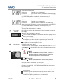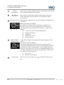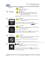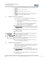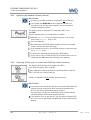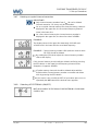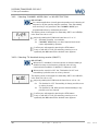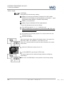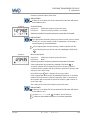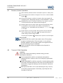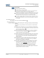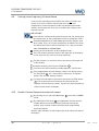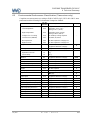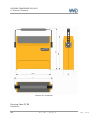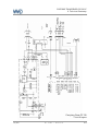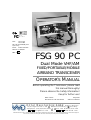
1
FCC ID: BVYFSG90 FAA: TSO C37d TSO C38d No. LBA.O.10.911/98 JTSO replaced by: ETSO: EASA.21O.1305 DFS-No.: B-7850/97 KBA: e1 03 5042 FSG 90 PC Dual Mode VHF/AM FIXED/PORTABLE/MOBILE AIRBAND TRANSCEIVER OPERATOR'S MANUAL Before operating the Transceiver, please read this manual thoroughly! Please observe the Safety Information! Keep for further use! Date of Issue Document no.: BA 154.90-EN May 2010 Article no. D10075 Dittel Messtechnik GmbH Avionics Division Erpftinger Straße 36 86899 Landsberg Germany Telephone +49 (0)8191/ 3351-0 Fax +49 (0)8191/ 3351-49 E-Mail: [email protected] Internet: www.dittel.com Dittel Messtechnik GmbH is certified to DIN EN ISO 9001:2000 and DIN EN ISO 14001:2005. It is an accredited manufacturer of aeronautical equipment DE.21G.0100, maintenance facility DE.145.0245, and development facility ETSO-2C37e/ETSO-2C38e. PORTABLE TRANSCEIVER FSG 90PC Operator's Manual Copyright - Service Copyright 2010 Dittel Messtechnik GmbH Service Information All rights reserved. This document contains proprietary information and such information may not be disclosed to others for any purpose nor used for manufacturing purposes without prior written permission of the manufacturer Dittel Messtechnik GmbH, 86899 Landsberg am Lech, Germany. In this document no mention is made of patents, trademark rights, or other proprietary rights which may attach to certain words or entries. The absence of such mention, however, in no way implies that the words or entries in question are exempt from such rights. Should any unusual problem arise or further information be desired, please contact your nearest DITTEL representative or the Dittel Messtechnik GmbH, Avionics Division, Erpftinger Strasse 36, 86899 Landsberg, Germany. The information in this Operator's Manual does not profess to include all the details of design, production, or variation of the equipment, or to cover all the possible contingencies which may arise during operation or maintenance. We welcome your comments concerning this Manual. Although every effort has been made to keep it free of errors, some may occur. When reporting a specific problem, please describe it briefly and include the Operator's Manual article number, paragraph or figure number, and the page number. Send your comments to Publications Department or via e-mail to: Erpftinger Strasse 36 86899 Landsberg am Lech Germany [email protected] Dittel Messtechnik GmbH Subject to technical changes 2 Printed in Germany DITTEL D10075 May 2010 PORTABLE TRANSCEIVER FSG 90PC Safety Information Safety Information Every radio, when transmitting, radiates energy into the atmosphere that may, under certain conditions, cause the generation of sparks. All users of our radios should be aware of the following warning: Do not operate this radio in an explosive atmosphere (petroleum fuels, solvents, dust, etc.)! During normal use, the radio will subject you to radio energy substantially below the level where any kind of harm is reported. TO ENSURE PERSONAL SAFETY Please observe the following simple rules: Only persons entitled may operate the FSG 90 PC! DO NOT lean over the equipment when opening the cover! If not properly tightened the spring steel band antenna may bounce out! DO NOT transmit when the antenna is very close to, or touching, exposed parts of the body, especially the face and eyes. DO NOT transmit on a busy channel! DO NOT transmit in closed vehicles, aircraft or inside buildings with the spring steel band antenna! This may cause malfunction of the avionics, trigger the airbag or confuse electronic equipment! Always operate the radio with a suitable external antenna! Assure appropriate lightning protection where elevated outdoor antennas are used. DO NOT press the transmit (PTT) key when not actually desiring to transmit. DO NOT allow children to play with any radio equipment containing a transmitter. DO NOT operate the radio whilst driving. It should also be noticed that the use of a hand held microphone while driving could constitute an offence under the Road Traffic Regulations in certain countries. DO NOT dispose worn out lead batteries with the household garbage. Always switch OFF the radio when plugging or unplugging the receptacle! Always switch OFF the radio first when starting an engine or vehicle! The FSG 90 PC may be used exclusively for communication on the airband frequencies. Unauthorized modifications and changes of the system are forbidden. When replacing defective parts use only original spare parts or standard parts recommended by the manufacturer! May 2010 DITTEL D10075 3 PORTABLE TRANSCEIVER FSG 90PC Safety Information Used Symbols In this manual the following symbols are used: DANGER! describes an immediate threatening danger! Failing to observe the note may cause death or heaviest injuries. WARNING! This warning note describes a dangerous high voltage. Failing to observe the note may cause death or severe injury! CAUTION! describes a special note for operation. Failing to observe the note may cause damage of the transceiver and/or stored data may be deleted! IMPORTANT! describes explanations and other useful hints. Failing to observe the note may cause degraded performance and/or unsatisfying operation! Environmental Protection After the implementation of the European Directive 2002/96/EU in the national legal system, the following applies: Electrical and electronic devices may not be disposed of with domestic waste. Consumers are obliged by law to return electrical and electronic devices at the end of their service lives to the public collecting points set up for this purpose or point of sale. Details to this are defined by the national law of the respective country. This symbol on the product, the instruction manual or the package indicates that a product is subject to these regulations. By recycling, reusing the materials or other forms of utilizing old devices, you are making an important contribution to protecting our environment. The portable airband transceiver FSG 90 PC contains a sealed lead-acid battery (identification "Pb"). Pb In most countries it is illegal to discard a lead-acid battery except by delivery to a retailer, a distributor, a manufacturer, or a collection, recycling, or smelting facility approved by the department. NEVER dispose worn out lead-acid batteries with the household garbage. 4 DITTEL D10075 May 2010 PORTABLE TRANSCEIVER FSG 90PC Table of Contents Table of Contents Copyright - Service ................................................................2 Safety Information .................................................................3 Table of Contents ..................................................................5 May 2010 1 General Description ............................................................7 1.1 1.2 1.3 1.4 1.5 1.6 Introduction.................................................................................................7 Application & Description of the FSG 90 PC...............................................7 Scope of Delivery .......................................................................................8 Operating License ......................................................................................7 System and Type Approval Information .....................................................8 Optional Accessories................................................................................10 2 Functional Description......................................................11 2.1 2.2 Introduction...............................................................................................11 Operator's Controls and Indicators...........................................................11 3 Set-up Procedure...............................................................19 3.1 3.2 3.3 3.4 3.4.1 3.4.2 3.4.3 3.4.4 3.4.5 3.4.6 3.4.7 3.4.8 3.4.9 3.4.10 3.4.11 3.4.12 3.4.13 3.4.14 Calling SET-UP without password ...........................................................20 Calling SET-UP with password ................................................................20 Interrupt the SET-UP procedure ..............................................................21 SET-UP procedure ...................................................................................21 Adjusting the automatic squelch threshold ............................................. 22 Adjusting the microphone sensitivity ....................................................... 22 Adjusting the Intercom volume................................................................ 23 Adjusting the Sidetone volume................................................................ 23 Adjusting the headset volume (receive) .................................................. 24 Selecting '25 kHz only' or combined 8.33/25 kHz channel spacing ........ 24 Deleting occupied channel memories ..................................................... 25 Selecting AF EXTERNAL (ON/OFF)....................................................... 25 Selecting 'CHANNEL MODE ONLY' or 'NO RESTRICTION'.................. 26 Selecting 'TX disabled' during receive (ON/OFF) ................................... 26 Service (ON/OFF) ................................................................................... 27 Optional module (ON/OFF) ..................................................................... 27 Entering a password................................................................................ 27 Reset ....................................................................................................... 28 4 Operation............................................................................29 4.1 4.2 4.3 4.4 4.5 4.6 4.7 4.8 4.9 4.10 Introduction...............................................................................................29 Battery Check...........................................................................................29 Battery Charging ......................................................................................30 Antenna - Antenna Jack SO 239..............................................................31 Microphone...............................................................................................31 Switching ON - Selecting Frequency/Channel Name - Volume...............32 Receive (Listen) Operation ......................................................................34 Transmit (Talk) Operation ........................................................................34 Storing a new Frequency/Channel Name ................................................36 Recall of stored frequencies/channel names: ..........................................36 DITTEL D10075 5 PORTABLE TRANSCEIVER FSG 90PC Table of Contents Table of Contents 4.11 4.12 4.13 4.14 4.15 4.16 4.17 4.18 Lighting the Frequency Display............................................................... 37 Turning OFF the radio ............................................................................. 37 External Power Supply ............................................................................ 37 Removing & Installing the Transceiver.................................................... 37 Battery Operating Times ......................................................................... 38 Siting........................................................................................................ 38 Base Operation........................................................................................ 38 Functional Checks ................................................................................... 39 5 ICAO Frequency / Channel Name Assignment in the combined 8.33 kHz / 25 kHz Operation ........................... 40 6 Technical Summary FSG 90 PC........................................ 41 6.1 6.2 6.3 6.4 6.5 General.................................................................................................... 41 Approvals................................................................................................. 42 Detailed Receiver Characteristics ........................................................... 42 Detailed Transmitter Characteristics ....................................................... 44 Environmental Performance Classification ............................................. 45 Certificates ........................................................................ 49 6 DITTEL D10075 May 2010 PORTABLE TRANSCEIVER FSG 90PC 1 General Description Section 1 1.1 General Description Introduction This operator's manual contains operating instructions for the fixed/ portable/ mobile VHF/AM Airband Transceiver FSG 90 PC of Dittel Messtechnik GmbH, 86899 Landsberg am Lech, Germany. 1.2 Application & Description of the FSG 90 PC The portable VHF/AM Airband Transceiver FSG 90 PC allows independent operation as an airborne or ground radio. Stationary, portable or mobile applications are possible. It consists of a portable case PC 90 and a Dual Mode VHF/AM COM Transceiver FSG 90 or FSG 90-H1, which can be simply inserted and positioned. This radio is working within the airband frequency range of 118.000 MHz to 136.975 MHz in either combined 8.33 kHz/25 kHz increments (2,278 channels) or '25 kHz only' increments (760 channels). The operating mode is Simplex, i.e. transmitting or receiving only in turns (two way communication). The RF output power of the radio FSG 90 is 6 Watt into 50 Ohms at 13.8 Vdc, the FSG 90-H1 is transmitting with 10 Watt into 50 Ohms at a power supply of 14.0 Vdc. The built-in rechargeable battery allows an independent operation of up to 85 hours (refer to paragraph 4.15, Battery Operating Times). Continuous operation is possible by the built-in charging unit or, externally, from a vehicle or aircraft DC supply. Microphone and antenna are retractable. External antennas, too, can be advantageously used. The unit features 99 non-volatile channel memories each in combined 8.33/25 kHz and in '25 kHz only' operation, 3 display modes, true Sidetone via headphone, TX and supply voltage indicator at the backlit display, TX time-out timer (2 minutes), a battery supply test, and a built-in loudspeaker. The lock-in type carrying handle and a protecting hood completes our PC 90 unit. May 2010 DITTEL D10075 7 PORTABLE TRANSCEIVER FSG 90PC 1 General Description 1.3 Scope of Delivery A complete Portable VHF/AM Airband Base Station FSG 90 PC consists of: A portable case PC 90 (A/N F10387), containing 12 Vdc/7.2 Ah lead calcium battery, charger for 115 Vac/230 Vac, 50 - 60 Hz, DC supply indicator, DC supply socket, microphone socket, antenna socket, loudspeaker, Snap-On cover - fits on top or bottom, and a Operator's Manual. a Dual Mode VHF/AM COM Transceiver FSG 90 or FSG 90-H1. a suitable, vertically polarized VHF airband antenna, frequency range minimum 118 to 137 MHz, 50 Ohm, e.g., spring steel band antenna A/N F10345, and a microphone, e.g., hand-hold dynamic microphone with PTTswitch A/N F10041. When operating on 24 Vdc sources a suitable 24 Vdc/12 Vdc Converter of at least 4 Amps must be used! 1.4 Operating License IMPORTANT! Ground operation always requires an individual operating license. Depending on national regulations, such license must be applied for at appropriate National Authorities, using suitable application forms. 1.5 System and Type Approval Information The Dual Mode VHF/AM Airband Transceiver FSG 90(X) complies for both the 8.33 kHz/25 kHz as well as 25 kHz channel spacing with all applicable National and International Type Approval requirements, for any airborne and ground operation. JTSO Authorization No. LBA.O.10.911/98 JTSO (LBA LuftfahrtBundesamt) based on *EUROCAE ED-23B Airborne requirement is met besides 8.33 kHz requirements also for the 25 kHz ONLY channel spacing. This JTSO Authorisation was replaced by ETSO Authorization EASA.21O.1305 in July 2009. This also includes Immunity according to ICAO ANNEX 10 against FM Broadcast Interference. This also includes fulfillment of specific audio filtering required in areas with CLIMAX operation in 25 kHz channel spacing. * Associated EUROCAE ED-14C / RTCA DO-160C Environmental requirements. * Associated EUROCAE ED-12B Software requirements based on ED-23B. 8 DITTEL D10075 May 2010 PORTABLE TRANSCEIVER FSG 90PC 1 General Description Reg TP No. A132937J, stringent German Type Approval requirements Reg TP 321 ZV 034 (airborne) and Reg TP 321 ZV 039 (ground). DFS (Deutsche Flugsicherung) No. B-7850/97 (ground) German Type Approval requirements. BZT No. B132705J, CE Conformity, * Associated with DIN/ISO 7637-1 DC supply in 12 V vehicle. FCC Compliance with Part 15 (receiver) and Part 87 (transmitter). EC-Type-Approval of a type of component with regard to Directive 72/245/EEC, as last amended by Directive 2006/28/EG. IMPORTANT! For the first time after one year, then every 2nd year, ground applications using 8.33 kHz channel spacing require checking of the high precision reference frequency (tolerance less than ± 1.5 ppm) and recalibration, if necessary! Every 4th year, airborne applications using 8.33 kHz channel spacing require checking of the high precision reference frequency (tolerance less than ± 5 ppm) and recalibration, if necessary! All applications in the 25 kHz channel spacing require no recalibration (frequency accuracy tolerance less than ± 20 ppm). All tolerances include the full operating temperature range of -20°C ... +55°C / -4°F ... +131°F. Checking and recalibration must be performed by the equipment manufacturer or through authorized and approved avionics services. This requires use of specified test equipment as well as applicable test procedures (software) released by the manufacturer. May 2010 DITTEL D10075 9 PORTABLE TRANSCEIVER FSG 90PC 1 General Description 1.6 Optional Accessories Article-No. F10345 Spring steel band antenna, swivel type, PL-259 connector W00043 Magnet mount vehicle rod antenna, incl. 4 m/13 ft cable, and UHF connector PL-259 W00066 Mobile Whip Antenna with shock spring, 118 - 137 MHz, incl. 5 m/ 16.5 ft cable, w/out UHF connector PL-259 F10314 Balloon antenna, 118-137 MHz, weatherproof - flexible - high efficiency, including 3 m/10 ft cable and UHF connector PL-259 W00013 Roof mounted weatherproof folded-top fiberglass antenna, UHFconnector, anti static, 1" mount E57328 UHF antenna connector PL-259 for antenna cable RG-213/U B01116 Antenna cable RG-213/U, low loss, for roof antenna W00013, please state length (in meters) F10041 Dyn. hand-held microphone incl. PTT-switch, coiled cord and 5-pole plug F10042 Dyn. hand-microphone/loudspeaker with PTT-switch, coiled cord and 5-pole plug F10125 Inline PTT-switch (U-94 A/U), coiled cord, 5-pole plug, to connect headset W00048, clip allows attaching to clothing W00048 10 Description Dynamic headset with PJ-plug, fits inline PTT-switch F10393 Car Cable, coiled cord, incl. 3-pole plug to supply station from 12 Vdc car battery (fits cigarette lighter socket, minus = ground) S20000 Converter 24 Vdc to 12 Vdc, 4 Amps, to operate the base Station from 24 Vdc sources like truck batteries etc. E61933 3-pole twist-lock DIN Connector, to fit into "12 V DC EXT." socket of carrying case PC 90. E08834 5-pole twist-lock DIN Connector, to fit into "MIC" socket of carrying case PC 90. E58411 Sealed lead accumulator, nominal 7.2 Ah, 12 VDC DITTEL D10075 May 2010 PORTABLE TRANSCEIVER FSG 90PC 2 Functional Description Section 2 2.1 Functional Description Introduction This section includes a functional description of each switch, push button, knob, socket, indicator and display located on the front or rear panel of the FSG 90 PC, together with operating instructions. After removing the Snap-On cover all controls to operate the transceiver are accessible. The cover can be pushed onto the rear side of the carrying case. DANGER! DO NOT lean over the equipment when opening the cover! If not properly tightened the spring steel band antenna may bounce out! 2.2 Operator's Controls and Indicators A front and back view of the FSG 90 PC is given on the last page of this manual. Please fold out the back flap when reading the operating instructions. Each position number of a control, knob, switch, etc., corresponds to the number of control, knob, switch, etc., given below. 1 ON/OFF-VOL 2 STO May 2010 Rotary step switch To turn ON the radio rotate the ON/OFF-VOL knob clockwise from the OFF position (dot). When power is activated all segments of the display are momentarily visible, he automatic squelch is activated the display shows the frequency/ channel name in that operating mode, which was used before last turning OFF. Rotating the ON/OFF-VOL knob clockwise increases - turning counterclockwise decreases the audio volume audible in the built-in loudspeaker (Receive only) or connected headphone (TX Sidetone and Receive). To turn OFF the radio rotate the ON/OFF-VOL knob fully counterclockwise (ccw) to the OFF position (dot). Blank display. Push button With the VHF/AM COM Transceiver FSG 90(X), up to 99 frequencies/channel names in each operating mode (combined 8.33/25 kHz mode or '25 kHz only' mode) may be stored in a nonvolatile memory. The channel memory numbers (1 99) are user programmable. DITTEL D10075 11 PORTABLE TRANSCEIVER FSG 90PC 2 Functional Description 2 STO continued Programming a frequency: 1. Set the frequency or channel name to be stored in the upper line at the display! 2. Initialize storing by pressing the STO button. 3. The last used channel memory number is displayed in the lower line. 4. A flashing "CH" shows "ready to store". 5. Select appropriate (new) channel memory number (1 to 99) by rotating the F/CH knob. 6. On a free channel memory an additional "F" (free) is displayed. 7. To enter the new frequency/channel name press the STO-button. The frequency/channel name will be stored under the adjusted channel memory number. 8. A previously stored frequency/ channel name will be overwritten. 9. The last used display mode is displayed. Programming in the SET-UP mode: In the SET-UP mode all settings must individually be confirmed by pressing the STO button. Otherwise the settings are not permanently stored. 3 SQ (SQUELCH) Push button After turning ON the radio FSG 90(X) the automatic squelch is always active. Momentarily pressing the SQ-Button puts the radio in the SQ-OFF mode (overrides the automatic squelch). Basic receiving noise is also audible during standby. Maximum receiving range. Increased current consumption. 'TX Disabled' is inactive, i.e. transmitting is possible even if the channel is busy. Momentarily pressing the SQ-Button once more puts the radio in the standard display mode, automatic squelch is active. No receiving noise during standby. Only reception of signals above SQ threshold to be heard. When the squelch is active 'TX Disabled' is active, i.e. transmitting is only possible if the channel is not busy. Note: For certain purposes 'TX Disabled' may be permanently switched OFF during SET-UP procedure. 12 DITTEL D10075 May 2010 PORTABLE TRANSCEIVER FSG 90PC 2 Functional Description 4 MD 5 TRANSFER Push button Momentarily pressing the Transfer button while in CHANNEL or DIRECT TUNE mode will return the radio to USE/STBY mode, or while in USE/STBY mode the last USE frequency will become the new STBY frequency and the last STBY frequency will become the new USE frequency, or while in the SET-UP mode will return the radio to the operation mode used before without power down. Only programmed settings stored previously by pressing the STO-button will be active. 6 F/CH Rotary control and push-button = dual function Momentarily pressing the F/CH knob while in the USE/STBY or DIRECT TUNE mode changes the access from kHz to MHz or vice versa. If there is no activity for 30 seconds the F/CH knob will return to the kHz access. While in the CHANNEL mode pressing the F/CH knob is without function. Rotating the F/CH knob while in the USE/STBY mode will increment or decrement the MHz or kHz portion of the STBY frequency with rollover at each band edge, while in the CHANNEL mode changes the channel memory number and corresponding frequency. Only channel numbers which were programmed before will appear, while in the DIRECT TUNE mode will increment or decrement the MHz or kHz portion of the USE frequency with rollover at each band edge. May 2010 Push button Repeatedly pressing the MD (mode)-button alters the display mode and display respectively: Use/STBY Mode: upper line USE frequency lower line STBY frequency Channel Mode: upper line USE frequency lower line channel memory number Direct Tune Mode: upper line USE frequency lower line blank DITTEL D10075 13 PORTABLE TRANSCEIVER FSG 90PC 2 Functional Description 7 Frequency Display 5-digit or 6-digit liquid crystal display (LCD), two lines, may be back-lit by pressing the "Test" button. IMPORTANT! When the FSG 90(X) is operating in the combined 8.33/25 kHz mode the channel name is displayed with 6 digits. When the FSG 90(X) is operating in the '25 kHz only' mode the frequency is displayed with 5 digits. Display of frequency and channel name corresponds to ICAO recommendations! Examples: Transceiver operates in the combined 8.33/25 kHz mode (6-digit display) Upper line: USE channel name (display 135.090 = 135.0916 MHz transmit and receive frequency) Lower line: STBY channel name (display 118.065 = 118.0666 MHz transmit and receive frequency) Supply indicator: 3 segments: 12.7 Vdc, supply OK TX indicator: OFF, radio receives. Transceiver operates in the '25 kHz only' mode (5-digit display) Upper line: USE frequency (display 135.87 = 135.875 MHz transmit and receive frequency) Lower line: STBY frequency (display 118.02 = 118.025 MHz transmit and receive frequency) Supply indicator: 3 segments: 12.7 Vdc, supply OK TX indicator: OFF, radio receives. Transceiver operates in the combined 8.33/25 kHz mode (6-digit display) Upper line: USE channel name (display 127.460 = 127.4583 MHz transmit and receive frequency) Lower line: Channel memory number (19) associated with the above USE channel name Supply indicator: 2 segments: 12.0 Vdc, battery ½ charged TX indicator: ON, radio transmits. Transceiver operates in the '25 kHz only' mode (5-digit display) Upper line: USE frequency (display 124.77 = 124.775 MHz transmit and receive frequency) Lower line: Channel memory number (75) associated with the above USE frequency Supply indicator: 2 segments: 12.0 Vdc, battery ½ charged TX indicator: ON, radio transmits. 14 DITTEL D10075 May 2010 PORTABLE TRANSCEIVER FSG 90PC 2 Functional Description STO button was pressed. Upper line: Channel name to be stored Lower line: Free channel memory number 07 (CH is flashing) After pressing the STO button once more the channel name 121.875 (= 121.875 MHz) will be stored in the channel memory 07. The last used display mode is displayed. STO button was pressed. Upper line: Channel name to be stored Lower line: Channel memory number 17 (CH is flashing) After pressing the STO button once more the channel name 121.375 (= 121.375 MHz) will be stored in the channel memory 17. A previously stored channel name will be overwritten. The last used display mode is displayed. 8 DC supply Indicator LED indicator to check the capacity of the built-in battery or external DC supply. When the red push-button is pressed at least 3 LEDs should light up to indicate sufficient capacity of the battery or DC supply. and only two or less LEDs light up either the battery should be recharged or the station should be powered by an external DC source of sufficient capacity (e.g. vehicle battery). the display of the transceiver is back-lit. 9 Loudspeaker 8 Ohm, 3 Watt, tropics-proof. To make received signals audible; volume adjustable with ON/OFF-VOL control 1 . Is not switched OFF when using a headset connected to 13 . 10 Antenna socket DANGER! NEVER TRANSMIT inside airplanes, vehicles or buildings without external antenna! Otherwise electronic equipment can be interfered. CAUTION! NEVER operate the radio without any antenna! UHF type antenna socket SO 239, 50 Ohms. Any 50 Ohms antenna with UHF type cable plug PL-259 and a frequency range of 118 137 MHz minimum may be connected to this antenna jack. For portable use in the open field we recommend our spring steel band antenna. In aircraft or ground vehicles, an external antenna must be used. For long range operation a base station folded top antenna, grounded for lightning protection, is recommended. May 2010 DITTEL D10075 15 PORTABLE TRANSCEIVER FSG 90PC 2 Functional Description 11 Antenna compartment When using our spring steel band antenna, A/N F10345, this antenna can be kept there without disconnecting. 12 Microphone compartment When using our hand-hold microphone with built-in push-to-talk switch, A/N F10041, this microphone can be kept there without disconnecting. 13 Microphone socket 5-pole twist-lock DIN socket to connect microphone, headphone and (2) (1) 14 16 ( 4) (5) NEW SOCKET! External Supply (1) 15 (3) (3) Fixing screws PTT-switch. Mating plug: article No. E08834 Any dynamic microphone (200 to 600 Ohms), headphone (ca. 300 Ohms), push-to-talk key, or dynamic type head-set can be connected to this socket. Wiring refer to Section 6, "90 PC, Circuit Diagram". (1) Common Ground (PTT switch/Headphone) (2) Dynamic microphone (3) Headphone (4) Microphone Ground (5) Push-to-talk key 3-pole twist-lock DIN socket to supply the radio by external 12 Vdc sources. Mating plug: article No. E61933 The capacity of the built-in battery may not be adequate due to frequent transmitting operations or very long operating times without possibility to recharge. Radio operation can be enabled through an external 12 Vdc power source such as an automobile battery via our Car Cable F10393 which fits into the cigarette lighter socket of most cars (minus on common ground). (1) Plus 12 Vdc (3) Minus 12 Vdc (Ground) Three cross recessed screws, M 3 case. 8, to fix the transceiver in the DITTEL D10075 May 2010 PORTABLE TRANSCEIVER FSG 90PC 2 Functional Description Rear panel: 16 Mains cable compartment WARNING! Risk of electric shock! DO NOT OPEN! WARNING! Changing the plug may only carried out by a trained specialist -electrician-! Please observe national safety regulations! Contains the mains cable of the built-in battery charger, length of cable: ca. 1.2 m. 17 DC Fuse WARNING! Always turn OFF radio and disconnect mains plug when replacing fuses! Fuse to protect the transceiver in case of heavy current. Contains 1 glass cartridge fuse, 18 Mains Fuses 5 20 mm, 6,3 Amps, time-lag. WARNING! Always turn OFF radio and disconnect mains plug when replacing fuses! Fuses to protect the charging unit. Contains 1 glass cartridge fuse each, 5 20 mm, 0.04 A time-lag. The fuses fit for both mains voltages, no change required. 19 Mains selector switch WARNING! Always turn OFF radio and disconnect mains plug when changing the mains voltage! The charging unit is factory set to 230 Vac mains voltage (position 230). When 110 115 Vac mains is available, set the mains selector switch by means of a coin or screwdriver 20 Ejector knob CAUTION! Always turn OFF the radio first when removing from its case! After removing three cross-recessed screws 15 and the matching plate on the front, the transceiver may be dismounted from its case by pressing this ejector knob. May 2010 DITTEL D10075 17 PORTABLE TRANSCEIVER FSG 90PC 2 Functional Description 18 DITTEL D10075 May 2010 PORTABLE TRANSCEIVER FSG 90PC 3 Set-up Procedure Section 3 Set-up Procedure This section contains a description of the Set-Up procedure to be carried out only once by an experienced avionics technician. To carry out the Set-Up procedure the radio must be installed into the Carrying Case and ready to use. DANGER! NEVER carry out a SET-UP during flight, important missions or applications! During SET-UP procedure the radio can neither receive nor transmit! IMPORTANT! The FSG 90(X) is factory pre-set for check and testing purposes. To achieve maximum performance it is therefore absolutely necessary to optimize the radio and to adapt the accessories used. Set-up should be performed only by an experienced technician. To carry out the set-up the radio must be ready for operation (antenna connected, power supply OK, operational microphone). If headsets are used turn volume control to maximum, if applicable. All frequencies, channel names, channel memory numbers etc., shown in the following illustrations, are examples! The following settings can be selected or adjusted (order): May 2010 1. Adjusting the automatic squelch threshold 2. Adjusting the microphone sensitivity 3. Adjusting the Intercom volume (headset) 4. Adjusting the Transmit Sidetone volume (headset) 5. Adjusting the headset volume (during Receive independent from speaker volume) 6. Selecting '25 kHz only' channel spacing or combined 8.33/25 kHz channel spacing. Confirmation with STO starts new mode at once. 7. Deleting occupied channel memories (one after the other) 8. Selecting AF External via loudspeaker ON = 1 or OFF = 0. 9. Selecting 'CHANNEL MODE' only = 1 or 'FREE FREQUENCY SELECTION' = 0 DITTEL D10075 19 PORTABLE TRANSCEIVER FSG 90PC 3 Set-up Procedure 3.1 10. Selecting 'TX disabled' ON = 1 or OFF = 0 during receive 11. Service, ON = 1 or OFF = 0 12. Optional module, ON = 1 or OFF = 0 13. Entering a password: protects against unauthorized changes of the radio parameters. Calling SET-UP without password Calling the SET-UP procedure without password is possible: a) at factory-new radios FSG 90(X), or b) at radios which are reset to a factory basic setting (refer to § 3.4.14, RESET), or c) at radios which are not protected by a password against unauthorized changes of the set-up adjustments. Turn OFF the radio (ON/OFF-VOL knob fully ccw). PRESS AND HOLD both MD and STO buttons, then turn ON the radio (rotate ON/OFF-VOL knob clockwise, approximately mid position). All segments of the display appear for a short moment then the display gets blank. Release the buttons. After releasing the buttons the display shows in the upper line alternately »FSG90« and »SET-UP«. If there is no activity for 60 seconds the radio will return to the mode used before. Momentarily pressing the MD button once will open the set-up menu to adjust the squelch threshold. Repeatedly pressing the MD button will open all other set-up menus in the order described before. 3.2 Calling SET-UP with password Calling the SET-UP procedure with password must be carried out at radios which are protected by a password against unauthorized changes of the set-up adjustments. Turn OFF the radio (ON/OFF-VOL knob fully ccw). PRESS AND HOLD both MD and STO buttons, then turn ON the radio (rotate ON/OFF-VOL knob clockwise, approximately mid position). All segments of the display appear for a short moment then the display gets blank. 20 DITTEL D10075 May 2010 PORTABLE TRANSCEIVER FSG 90PC 3 Set-up Procedure Release the buttons. After releasing the buttons the display shows in the upper line alternately »FSG90« and »SET-UP«, in the lower line 5 dashes. If there is no activity for 60 seconds the radio will return to the mode used before. With the F/CH knob set the first digit of your password (the first dash changes to digit). Confirm the first digit by pressing the F/CH knob. The second digit is ready to be adjusted. With the F/CH knob set the second digit of your password (the second dash changes to digit). Confirm the second digit by pressing the F/CH knob. Continue till all five digits of your password are entered. Confirm the last digit input by pressing the STO button. This will open the set-up menu to adjust the squelch threshold. Repeatedly pressing the MD button will open all other set-up menus in the order described before. Entering a wrong password will return the set-up to the initial status (5 dashes). After the fourth attempt to open the set-up with a wrong password the radio returns to the operation mode used before trying to open the set-up. The FSG 90(X) is operational. 3.3 Interrupt the SET-UP procedure The SET-UP procedure may be interrupted any time: Usually by turning OFF the power (ON/OFF-VOL knob fully ccw). All changed and individually stored adjustments (by pressing the STO button) are permanently stored and effective after turning ON the radio again. or by pressing the Transfer button ( ). The radio returns to the operation mode used before. All changed and individually stored adjustments up to now (by pressing the STO button) are permanently stored and effective. 3.4 SET-UP procedure IMPORTANT! The settings can be done in any order! Repeatedly pressing the MD button opens the menus step by step. Only settings confirmed by finally pressing the STO key are permanently stored and effective. When pressing the STO button the upper segment of the Onboard May 2010 DITTEL D10075 21 PORTABLE TRANSCEIVER FSG 90PC 3 Set-up Procedure supply indicator will light up to confirm storing visually. 3.4.1 Adjusting the automatic squelch threshold The display shows in the upper line alternately »SET« and »SQUEL«, in the lower line »LO«, »MED1«, »MED2« or »HI«. Adjust by rotating the F/CH knob the squelch threshold as required. The lower line shows: LO ca. 1.0 µV / -107 dBm (Standard setting) MED1 ca. 2.5 µV / -99 dBm MED2 ca. 5.0 µV / -93 dBm HI ca. 8.0 µV / -89 dBm (this setting exceeds the required minimum sensitivity; adjust only for test purposes at very strong interference levels!) Confirm your adjustment by pressing the STO button! If you want to carry on with the SET-UP procedure press once or repeatedly the MD button till the desired menu appears. 3.4.2 Adjusting the microphone sensitivity IMPORTANT! This adjustment is important particularly when FSG 90 PC is used in noisy environment like turboprop airplanes or vehicles: Turn your radio OFF (ON/OFF-VOL knob fully ccw). The FSG 90(X) should be turned ON only after engine or motor start-up. Select a free frequency/channel name (no communication audible). Then call the SET-UP procedure. During this adjustment the transmitter is in operation. Carry out adjustment quickly! Up to two microphones of the same type may be connected parallel to the MIC input (dynamic type). Parallel operated microphones must have the same specifications. This adjustment has to be repeated when changing microphones (brand, type or number) The display shows in the upper line alternately »SET« and »MICRO«. ONLY FOR ENGINE POWERED AIRPLANES AND VEHICLES: RUN THE ENGINE IN IDLE (because of noise level). Press and hold the PTT key. Talk in a loud, clear voice with the 22 DITTEL D10075 May 2010 PORTABLE TRANSCEIVER FSG 90PC 3 Set-up Procedure microphone one or two inches from your lips. While talking the microphone level is measured. By turning the F/CH knob left or right set the upper dash line to three to four segments (the lower dash line shows only informative the actual range). Release the PTT key and stop talking. RUN THE ENGINE IN CRUISING SPEED. Press and hold the PTT key for at least 5 seconds, do not talk! The upper dash line should show not more than one segment. If the display shows more than one segment the mic input is too sensitive. Repeat adjustment with less sensitivity (only two to three segments visible when talking). Confirm your adjustment by pressing the STO button! If you want to carry on with the SET-UP procedure press once or repeatedly the MD button till the desired menu appears. 3.4.3 Adjusting the Intercom volume NOT APPLICABLE WHEN THE FSG 90(X) IS OPERATED IN A CARRYING CASE PC 90! 3.4.4 Adjusting the Sidetone volume IMPORTANT! Sidetone audible during transmit is only possible via headphones (if applicable set maximum volume at the headset) During this adjustment the transmitter is in operation. Carry out adjustment quickly! The microphone(s) sensitivity has to be adjusted properly (refer to paragraph 3.4.2) The display shows in the upper line alternately »SET« and »SIDE«. Press and hold PTT key, Talk in a loud, clear voice with the microphone one or two inches from your lips. While talking adjust with the F/CH knob a convenient volume in your headphone (the segments show the actual range). If more than four segments are shown overmodulation occurs. Release the PTT key. Confirm your adjustment by pressing the STO button! If you want to carry on with the SET-UP procedure press once or repeatedly the MD button till the desired menu appears. May 2010 DITTEL D10075 23 PORTABLE TRANSCEIVER FSG 90PC 3 Set-up Procedure 3.4.5 Adjusting the headset volume (receive) IMPORTANT! Receiving is possible via built-in loudspeaker and headphone. First set with the ON/OFF-VOL knob loudspeaker volume to a convenient level, and then adjust with the set-up procedure a suitable headphone volume. The display shows in the upper line alternately »SET« and »PHONE«. With the speaker noise or communication is audible. With the ON/OFF-VOL knob set speaker output to a convenient level, leave ON/OFF-VOL knob as it is. Put on headphone. By rotating the F/CH knob adjust headphone level to a suitable volume. The dashes show the range. If the adjustment range is not sufficient increase or decrease with the ON/OFF-VOL knob. Confirm your adjustment by pressing the STO button! If you want to carry on with the SET-UP procedure press once or repeatedly the MD button till the desired menu appears. 3.4.6 Selecting '25 kHz only' or combined 8.33/25 kHz channel spacing The display shows flashing in the upper line »SET«, in the lower line either »25« or »8.33«. By rotating the F/CH knob select the required channel spacing: »25« = '25 kHz only' channel spacing »8.33« = combined 8.33 and 25 kHz channel spacing. IMPORTANT! Confirm the new channel spacing by pressing the STO button! The selected channel spacing becomes active and simultaneously SET-UP procedure will automatically be finished. The radio returns to the last used display mode and the settings confirmed with the STO button became effective. If you want to carry on with the SET-UP procedure call again SETUP. Press once or repeatedly the MD button till the required menu appears. 24 DITTEL D10075 May 2010 PORTABLE TRANSCEIVER FSG 90PC 3 Set-up Procedure 3.4.7 Deleting occupied channel memories IMPORTANT! Only channel memory numbers from 5 99 can be deleted. Channel memories 1 to 4 may only be overwritten. On an occupied channel memory the channel memory number is displayed in the upper line, the associated frequency/channel name in the lower line. On a free channel memory the channel memory number is displayed in the upper line, the lower line shows »FREE«. EXAMPLE: The display shows in the upper line alternately »CLR 05« and »CH 05« and in the lower line the associated frequency. EXAMPLE: Channel memory number »39« (with the channel name 132.765) should be deleted. By rotating the F/CH knob adjust the channel memory number »39« at the display. If this channel memory should really be deleted confirm by pressing the STO button. In the lower line the frequency/channel name disappears, it appears »FREE«. If further memory channels should be deleted adjust with the F/CH knob the channel memory number concerned and delete each by pressing the STO button. If you want to carry on with the SET-UP procedure press once or repeatedly the MD button till the desired menu appears. 3.4.8 Selecting AF EXTERNAL (ON/OFF) NOT APPLICABLE IF FSG 90(X) IS OPERATED IN A CARRYING CASE PC 90! May 2010 DITTEL D10075 25 PORTABLE TRANSCEIVER FSG 90PC 3 Set-up Procedure 3.4.9 Selecting 'CHANNEL MODE ONLY' or 'NO RESTRICTION' IMPORTANT! For certain applications (usually ground operation only) selecting all frequencies by the operator may be restricted. Then transmitting and receiving is only possible in the CHANNEL MODE, preprogrammed before by authorized personnel. The display shows in the upper line alternately »SET« and »FREQ«, in the lower line »0« or »1«. Adjust by rotating the F/CH knob lower line to "0" or "1". 0= Standard operation, no restriction. 1= CHANNEL MODE only, no other frequencies/channel names adjustable by operator. Confirm your adjustment by pressing the STO button! Carry on with the SET-UP procedure by pressing once or repeatedly the MD button till the desired menu appears. 3.4.10 Selecting 'TX disabled' during receive (ON/OFF) IMPORTANT! Whenever 'TX disabled' is ON and squelch is ON transmitting is disabled as long as the frequency/channel name is busy (communication audible). In addition TX Sidetone is OFF. Whenever the squelch is OFF the 'TX disabled' is OFF and transmitting is possible even on a busy channel. The display shows in the upper line alternately »SET« and »BLOC«, in the lower line »0« or »1«. Adjust by rotating the F/CH knob the lower line to »0« or »1«. 0= 'TX disabled' is OFF. Transmitting is always possible, even on a busy channel. 1= 'TX disabled' is ON. With squelch ON transmitting is only possible on a free channel. Confirm your adjustment by pressing the STO button! Carry on with the SET-UP procedure by pressing once or repeatedly the MD button till the desired menu appears. 26 DITTEL D10075 May 2010 PORTABLE TRANSCEIVER FSG 90PC 3 Set-up Procedure 3.4.11 Service (ON/OFF) IMPORTANT! For approved Avionics Shops only! No regular operation in this mode! The display shows in the upper line alternately »SET« and »SERV«, in the lower line »0«. 0 = STANDARD MODE, Service OFF. If required, confirm adjustment by pressing the STO button! Carry on with the SET-UP procedure by pressing the MD button. 3.4.12 Optional module (ON/OFF) IMPORTANT! In this radio without function. The display shows in the upper line alternately »SET« and »OPTI«, in the lower line »0«. 0= STANDARD MODE, Optional module OFF. Carry on with the SET-UP procedure by pressing the MD button. 3.4.13 Entering a password IMPORTANT! When the SET-UP of your radio is protected by a password it cannot be changed by any unauthorized persons without knowledge of the password. Your password consists of five digits! The display shows in the upper line alternately »SET« and »PASS«, in the lower line »00000«. If you don't want to enter a password and your SET-UP procedure is finished leave the SET-UP menu by pressing the TRANSFER ( ) button, or turn OFF the radio (ON/OFF-VOL knob). If you want to enter a password proceed as follows: Rotate the F/CH knob. Adjust the first digit (0 . 9). Confirm the first digit by pressing the F/CH knob. Adjust the second digit of your password by rotating the F/CH knob. Confirm again by pressing the F/CH knob. The third digit is ready now. Continue as described above for the third, fourth and fifth digit. Make sure the complete password corresponds to your idea. Confirm the password by pressing the STO button! From now on a new SET-UP may be called only after entering the password first! May 2010 DITTEL D10075 27 PORTABLE TRANSCEIVER FSG 90PC 3 Set-up Procedure 3.4.14 Reset CAUTION! Every RESET to the factory setting deletes all your pre-set memory channels 5 to 99 (in both 8.33/25 kHz and 25 kHz only mode)! Memory channels 1 - 4 get programmed with 118.00 or 118.005 respectively deletes your password! delete all your individual SET-UP adjustments! To reset all adjustments proceed as follows: Turn OFF the radio (ON/OFF-VOL knob fully ccw). PRESS AND HOLD simultaneously the buttons MD, STO and SQ, then turn ON the radio (rotate ON/OFF-VOL knob clockwise, approximately mid position). All segments of the display appear for a short moment then the display gets blank. Release the buttons. After releasing the three buttons the display shows in the upper line alternately »SET« and »RESET«, in the lower line »0«. If there is no activity for 60 seconds the radio will return to the mode used before. With the F/CH knob set lower line to "1". Confirm RESET by pressing the STO button. The upper segment of the Onboard Supply Indicator will light up momentarily. The VHF radio FSG 90(X) is now operable in the factory setting. 28 DITTEL D10075 May 2010 PORTABLE TRANSCEIVER FSG 90PC 4 Operation Section 4 4.1 Operation Introduction This section contains a basic operation procedure for the FSG 90 PC portable airband transceiver. This instruction is only applicable for a radio which is already optimized by the Set-Up procedure (refer to Section 3, SET-UP PROCEDURE). DANGER! DO NOT OPERATE THIS RADIO IN AN EXPLOSIVE ATMOSPHERE (PETROLEUM FUELS, SOLVENTS, DUST, ETC.). DO NOT lean over the equipment when opening the cover! If not properly tightened the spring steel band antenna may bounce out! After removing the Snap-On cover all controls to operate the transceiver are accessible. The cover can be pushed onto the rear side of the carrying case. A front and back view of the FSG 90 PC is given on the last page of this manual. Please fold out the back flap when reading the operation instructions. 4.2 Battery Check If applicable, disconnect built-in charger from mains first, before checking the battery supply. Press the red test button of the battery indicator The LED indicators 8 will light up. 8 . 5 LEDs ON = 3 to 4 LEDs ON = battery fully charged, supply OK! battery partially discharged; reduced operation time when powered only from the battery. 2 or less LEDs ON = battery discharged. The battery should be recharged or the radio should be powered by an external 12 Vdc source of adequate capacity (e.g. automobile battery). May 2010 DITTEL D10075 29 PORTABLE TRANSCEIVER FSG 90PC 4 Operation Additionally the supply is permanently monitored when the radio is switched ON: 3 segments 12.7 Vdc Battery fully charged 2 segments 12.0 Vdc Battery charged approx. ½, reduced operating time 1 segment 11.0 Vdc Battery almost empty, cease transmitting! 3 segments flashing 10 - 11 Vdc Emergency operation Continuous flashing during STBY 8.59.5 Radio Vdc will soon switch OFF itself! IMPORTANT! If the Supply Indicator even blinks continuously in STANDBY mode it indicates a discharged battery. The radio should then be switched OFF at once and the battery recharged as soon as possible. The battery must always be recharged immediately after an extensive discharge because this incurs the risk of deterioration and permanent damage - this risk is increased if a discharged battery is stored in that state. 4.3 Battery Charging Charging should be done within the ambient temperature range of +10°C to +40°C. First check the line voltage and set it with the voltage selector switch 19 on the back, if necessary. Take out the mains cord from its compartment 16 and connect it to a wall socket. The transceiver may be operated while charging. Charging lasts up to 30 hours depending on the state of the battery. Overcharging the battery is not possible due to automatic controlled charging function. For trickle charging or buffer operation the charger can be left unattended continuously connected to mains. A fully charged battery can be stored for several months. 30 DITTEL D10075 May 2010 PORTABLE TRANSCEIVER FSG 90PC 4 Operation 4.4 Antenna - Antenna Jack SO 239 DANGER! NEVER TRANSMIT in vehicles, aircraft or inside buildings with the spring steel band antenna! This may cause malfunction of the avionics, trigger the airbag or mix-up electronic equipment! Always operate the radio with a suitable external antenna! NEVER OPERATE the radio without any antenna! The spring steel band antenna (Article-No. F10345), connected to the SO 239 antenna jack 10 , can be replaced by any other 50 Ohm antenna with UHF type PL-259 cable plug and a frequency range of 118 137 MHz minimum. For long range operation a base station folded top antenna, grounded for lightning protection, is recommended. To operate the radio in aircraft or ground vehicles a suitable external antenna should always be used. Ensure the plug of your antenna or antenna cable is securely tightened. If the spring steel band antenna is used, pull it out of its compartment 11 and adjust it in a vertical position by tightening the screwed cap and wing screw. 4.5 Microphone The hand-held dynamic microphone with push-to-talk switch (ArticleNo. F10041) can be replaced by any other dynamic microphone (200 to 600 Ohms) with PTT switch or a head-set for dynamic type systems with additional PTT switch (mating 5pole plug: Article-No. E08834, wiring to station, refer to Section 6, Circuit Diagram 90 PC). Connect microphone; ensure the plug is secured by the twist-lock cap. May 2010 DITTEL D10075 31 PORTABLE TRANSCEIVER FSG 90PC 4 Operation 4.6 Switching ON - Selecting Frequency/Channel Name - Volume CAUTION! The FSG 90 PC should be turned on after engine start-up. This is a simple precaution which helps to protect the solid state circuitry and extends the operating life of your avionics equipment. IMPORTANT! »Frequency« (25 kHz spacing) and »Channel Name« (combined 8.33/25 kHz spacing) are ICAO terms! Frequent transmissions as well as large receiving volume reduce the operating time when radio is only powered by the built-in battery! Turn the radio FSG 90(X) ON by rotating the ON/OFF-VOL knob 1 clockwise. Momentarily all segments of the display are visible. Last used display mode and frequency are displayed. A warm-up period for the transmitter is not required. However, at temperatures of -20°C, the LC display needs approximately one second until it is fully visible when the frequency or display mode is changed. To change the display mode: Push once or twice the MD button 4. Selecting the appropriate USE (active) frequency/channel name depends on display mode: EXAMPLE: STANDARD: USE/STBY (Standby) Mode Upper line: Lower line: USE/active frequency/channel name Standby frequency/channel name Selecting another frequency/channel name than indicated: At the lower line select appropriate kHz portion by rotating F/CHknob 6 . A clockwise rotation will increment the previous frequency while a counterclockwise rotation will decrement the previous frequency with rollover at each band edge. Push F/CH knob 6 ; this changes the access to MHz. At the lower line select appropriate MHz portion by rotating F/CHknob 6 . A clockwise rotation will increment the previous frequency while a counterclockwise rotation will decrement the previous frequency with rollover at each band edge. Push the Transfer Button 5. The last standby frequency/channel name (lower line) will become the new active frequency/channel name (upper line) and the last active frequency/ channel name will become the new STBY 32 DITTEL D10075 May 2010 PORTABLE TRANSCEIVER FSG 90PC 4 Operation frequency/channel name (lower line). IMPORTANT! If there is no activity for 30 seconds the F/CH knob will return to the kHz access. EXAMPLE: Channel Mode: Upper line: Lower line: USE/active frequency/channel name Channel memory number, associated Selecting another frequency/channel name than indicated: IMPORTANT! The appropriate operating frequency/channel name must be stored already in a channel memory (refer to paragraph 4.9, Storing a new Frequency/ Channel Name). Select appropriate channel memory number together with the associated frequency/channel name by rotating the F/CH knob 6 . EXAMPLE: Direct tune Mode: Upper line: Lower line: USE/active frequency/channel name blank Selecting another frequency/channel name than indicated: Select appropriate kHz portion by rotating F/CH-knob 6 . A clockwise rotation will increment the previous frequency while a counterclockwise rotation will decrement the previous frequency with rollover at each band edge. Push F/CH knob 6 ; this changes the access to MHz. Select appropriate MHz portion by rotating F/CH-knob. A clockwise rotation will increment the previous frequency while a counterclockwise rotation will decrement the previous frequency with rollover at each band edge. The setting is the new active frequency/channel name. IMPORTANT! If there is no activity for 30 seconds the F/CH knob will return to the kHz access. Rotate ON/OFF-VOL knob 1 clockwise, about half way. Continue with either Receive or Transmit Operation May 2010 DITTEL D10075 33 PORTABLE TRANSCEIVER FSG 90PC 4 Operation 4.7 Receive (Listen) Operation After switching ON the radio the automatic squelch is always ON. If the display mode shall be changed: Push once or twice the MDbutton 4 . If the active frequency shall be changed: refer to paragraph 4.6, Switching ON - Selecting Frequency/ Channel Name - Volume DO NOT press the PTT (push to talk) key if you want to receive! Transmit Indicator at the display must not appear! Normal signals are received, weak signals and interfering pulses are disabled. Set the volume of the built-in loudspeaker or headphone to a comfortable level by rotating ON/OFF-VOL knob 1 in 15 steps. Weak signals can be received if the squelch circuit is switched OFF by pressing the SQ button 3 . Then typical RX noise is heard during communication breaks. Pressing the SQ button 3 switches the squelch circuit ON again. IMPORTANT! Switching OFF the squelch only makes sense if long range reception shall take place. Thus the radio is noisy during Standby operation, but no weak signals are suppressed and the full receiving range is available! Notice increased current consumption when Squelch is switched OFF! 4.8 Transmit (Talk) Operation DANGER! Every radio, when transmitting, radiates energy into the atmosphere, therefore: Do not operate this radio in an explosive atmosphere (petroleum fuels, solvents, dust, etc.)! Danger by generation of sparks. NEVER TRANSMIT in vehicles, aircraft or inside buildings with the spring steel band antenna! This may cause malfunction of the avionics, trigger the airbag or mix up domestic electronic equipment! Never place the radio such as the antenna gets very close to, or touching, exposed parts of the body, especially the face, shoulder or the eyes. 34 DITTEL D10075 May 2010 PORTABLE TRANSCEIVER FSG 90PC 4 Operation IMPORTANT! Please keep radio discipline! Transmit only on a clear channel. Care for an all-round obstacle free location of your antenna; the called station should be within "line-of-sight" distance. Volume is very important. Increasing speaking levels while the lips are facing the microphone (distance 1" to 2") will increase clarity. Talk slow, make each word a precise and individual entity. The radio is equipped with a TX time-out-timer (2 minutes). This is used to limit the duration of calls and to guard against accidental PTT locking. If the display mode shall be changed: Push once or twice the MD-button 4 . If the active frequency shall be changed: Refer to 4.6 Switching ON - Selecting Frequency/Channel Name Volume. Transmitting is only possible on a free channel (no communication audible). If you have to transmit (e.g. in case of emergency) although the channel is busy, the Transmit Disabled circuit may be turned OFF by pressing the SQ button 3 . When the DITTEL hand-held microphone, article-no. F10041 is used, take it out of its compartment 12 . Press and hold the orange colored PTT (push to talk) key. Talk in a loud, clear voice with the microphone one or two inches from your lips. Make each transmission as brief as possible. As long as the PTT key is pressed the Transmit Indicator at the display appears! Release the PTT key to end the transmission and to open the channel for reception; the Transmit Indicator must disappear. Switch Squelch ON again, if applicable. The radio is equipped with a TX time-out-timer. This is used to limit the duration of transmissions to two minutes. When the transmitter is keyed continuously longer than 2 minutes the display of the FSG 90(X) starts flashing and transmission is disabled. If you have to make calls longer than 2 minutes momentarily release the PTT key and press again. The TX timeout-timer starts for another 2 minutes. May 2010 DITTEL D10075 35 PORTABLE TRANSCEIVER FSG 90PC 4 Operation 4.9 Storing a new Frequency/Channel Name In each active operating mode (8.33/25 kHz mode or '25 kHz only' mode) up to 99 non-volatile channel memories can be user programmed. Channel memories of the non-active mode remain stored in the background. They are accessible after calling up the respective mode. IMPORTANT! Free selection of frequencies/channel names and new storing may be restricted due to Set-Up adjustment (refer to paragraph 3.4.9)! Channel memories 1 to 4 are always pre-set and may be used when called. They can only be changed but not deleted. Ex works and after Master Reset channel memories 1 to 4 are pre-set with either 118.00 MHz or 118.005 MHz! Storing can be initialized in all three display modes. The USE frequency/channel name in the upper line of the display can be stored to any of the 99 channel memories. Set the frequency or channel name to be stored in the upper line at the display! Initialize storing by pressing the STO button 2 . The last used channel memory number appears, "CH" flashes. Select appropriate channel memory number (1 to 99) by turning the F/CH knob 6 . On a free memory channel an "F" appears before "CH" and the memory number. To enter the new frequency/channel name press the STO-button 2 . The frequency/channel name will be stored under the selected channel memory number. A previously stored frequency/ channel name will be overwritten. 4.10 Recall of stored frequencies/channel names: By pushing once or twice the MD-button 4 select the CHANNEL mode. By rotating the F/CH knob 6 set appropriate channel memory number with its associated frequency/channel name at the display. Only channel numbers that have been programmed before will appear. Now the radio operates on that frequency/channel name indicated at the display. 36 DITTEL D10075 May 2010 PORTABLE TRANSCEIVER FSG 90PC 4 Operation 4.11 Lighting the Frequency Display Lighting of the frequency display 7 is activated by pressing the red test button of the battery indicator 8 . 4.12 Turning OFF the radio Always turn OFF the radio after use by rotating the ON/OFF-VOL switch 1 to the fully ccw position to prevent unnecessary discharge of the battery. Place the microphone in its compartment 12 . Loosen screwed cap and wing screw of the spring steel band antenna and push the upper part into its compartment 11 . Bend the remaining portion so, that the Snap-On cover can be placed in position. DANGER! Always tighten the antenna's screwed cap and wing screw before closing the cover; otherwise the spring steel band antenna will bounce out, when the cover is lifted again! 4.13 External Power Supply The capacity of the built-in battery may not be adequate due to frequent transmitting operations or very long operating times without possibility to recharge. Radio operation can be enabled through an external 12 Vdc power source such as an automobile battery via our Car Cable F10393 which fits into the cigarette lighter socket of most cars (minus on common ground). Mating plug: article No. E61933. 4.14 Removing & Installing the Transceiver IMPORTANT! Switch OFF the radio first! This is a simple precaution which helps protect the solid state circuitry and extends the operating life of your avionics equipment. To dismount the transceiver FSG 90(X) from its case, remove the three cross-recessed screws 15 and lift off the matching plate. Eject the transceiver from the rear connector of the case by pressing ejector knob 20 on the rear. Pull out transceiver. To install the transceiver, carefully insert it into the case. The plugs mate automatically to the case's wiring. Put on the matching plate and fix it by the three cross-recessed screws 15 . Check fixing and function. May 2010 DITTEL D10075 37 PORTABLE TRANSCEIVER FSG 90PC 4 Operation 4.15 Battery Operating Times Prerequisite: Maximum RX audio volume Max. current drain Lead Accumulator 12 Volts 7.2 Ah .11 A STBY, w/out RX 2.5 A 1.0 A .11 A 5% TX 5% RX STBY 2.5 A 1.0 A .11 A 2.5 A 1.0 A .11 A 90% 10% 20% 70% 20% 40% 40% TX RX STBY TX RX STBY Temperature - 20°C 38 h 12.30 h 6.00 h 3.10 h Temperature +20°C 62 h 20.10 h 10.00 h 5.20 h Temperature +50°C 66 h 22.10 h 11.10 h 6.00 h Prerequisite: Minimum RX audio volume Max. current drain Lead Accumulator 12 Volts 7.2 Ah 4.16 .085 A 2.5 A .25 A .08 A STBY, w/out RX 5% TX 5% RX STBY 2.5 A .25 A .08 A 2.5 A .25 A .08 A 90% 10% 20% 70% 20% 40% 40% TX RX STBY TX RX STBY Temperature -20°C 57 h 15.50 h 8.50 h 4.40 h Temperature +20°C 85 h 26.10 h 14.30 h 7.50 h Temperature +50°C 90 h 28.40 h 16.20 h 8.40 h Siting The radio operates in the VHF frequency band, this is a Line-Of-Sight (LOS) frequency; therefore, siting of the radio greatly affects its operating range. The longest range is normally obtained when a direct LOS is maintained between the radios. Use of hilltop, roof or tower locations will increase the LOS range. Location in valleys with intervening hills, behind vehicles or buildings or in dense woods may reduce or prevent communications. If possible, avoid antenna locations near electrical interference sources, such as computers, power and telephone lines, radar, welders and electrical generators. 4.17 Base Operation To operate the radio as a base station, a weather-proof anti static and lightning protected folded-top antenna is ideally suited. The antenna should be mounted vertically and elevated as high as possible on a roof, horizontally free of obstacles. The antenna mast has to be grounded and anchored, as necessary. For a distance of up to 15 m the antenna cable may be a RG 58 C/U type, for longer distances always use the cable type RG 213/U (low loss). In general, the antenna cable should not be longer than necessary. 38 DITTEL D10075 May 2010 PORTABLE TRANSCEIVER FSG 90PC 4 Operation 4.18 Functional Checks If the transceiver FSG 90 PC does not operate correctly, check the following: Is the required frequency/channel name visible in the upper line? Adjust required frequency/channel name! Is battery supply sufficient? Observe onboard supply indicator particularly during transmit, at least one segment must be shown! Weak RX signal? Press SQ button = switch OFF squelch circuit! Weak TX signal? Check microphone, mic SET-UP, radio, or antenna system! Is the voice volume too low? Speak loud and clear while the lips are facing the microphone! Try another location! Make sure that transceiver's antenna is vertically positioned and is not screened by nearby placed metallic objects or buildings. Singing during transmit? Adjust Sidetone more quietly; put on headset; keep microphone in other position! Rattles when receiving? Metal propellers between transmitting airborne radio and base station antenna! Called station hears carrier, but no voice? Check microphone and contacts on microphone jack! Noisy - distorted - garbled? Suppress electrical interference of motorized aircraft or vehicle (generator, regulator), check antenna system; check antenna-, microphone- and radio- connector for proper seat! Change location! Flashing display, transmitter switches off itself? PTT key sticks! Check PTT key and cables. Transmitter was keyed longer than 2 minutes. Release PTT key, normal operating is possible again. In case of emergency turn radio OFF and switch ON again, permits another two minutes to transmit. In case of doubt, compare operation of the transceiver with another transceiver on the same location or call another station. If service is necessary please consult your authorized dealer or an approved avionics workshop. May 2010 DITTEL D10075 39 PORTABLE TRANSCEIVER FSG 90PC 5 ICAO Frequency / Channel Name Section 5 ICAO Frequency / Channel Name Assignment in the combined 8.33 kHz / 25 kHz Operation The following table shows transmit and receive frequency, the respective channel spacing and the associated display of the FSG 90 in the range from 118.000 MHz to 118.1000 MHz. This assignment also applies of course to all other frequencies between 118.1000 MHz and 136.9750 MHz. Transmit and Receive frequency (MHz) Channel spacing 8.33/25 kHz Mode Channel Name = Display at FSG 90 25 kHz Mode Frequency = Display at FSG 90 118.0000 25 118.000 118.00 118.0000 8.33 118.005 118.0083 8.33 118.010 118.0166 8.33 118.015 118.0250 25 118.025 118.0250 8.33 118.030 118.0333 8.33 118.035 118.0416 8.33 118.040 118.0500 25 118.050 118.0500 8.33 118.055 118.0583 8.33 118.060 118.0666 8.33 118.065 118.0750 25 118.075 118.0750 8.33 118.080 118.0833 8.33 118.085 118.0916 8.33 118.090 118.1000 25 118.100 118.1000 8.33 118.105 and so on 40 etc DITTEL D10075 118.02 118.05 118.07 118.10 etc May 2010 PORTABLE TRANSCEIVER FSG 90PC 6 Technical Summary Section 6 6.1 Technical Summary FSG 90 PC General Frequency Range Number of Channels Transmitter Output FSG 90 Transmitter Output FSG 90-H1 : 118.000 MHz ... 136.975 MHz, 8.33 kHz and/or 25 kHz increments : 2,278 in the combined 8.33/25 kHz channel spacing, free selectable, or 760 in the 25 kHz only channel sp selectable : 6 Watt / 50 ; ca 20 W PEP @ 13.8 Vdc : 5 Watt / 50 ; ca 16 W PEP @ 12.0 Vdc 10 Watt / 50 ; ca 30 W PEP @ 14.0 Vdc 8 Watt / 50 ; ca 25 W PEP @ 12.0 Vdc Receiver Sensitivity, m = 30%/ 1 kHz Frequency Accuracy : 2.0 µV EMF/ 107 dBm/50 Ohms for 6 dB (S+N/N) : < ± 1 ppm at 0°C +40°C, < ± 1.5 ppm at -20°C +55°C : AF Output (K 10%) 2 Watts into 8 Ohms and 100 mW into 600 Ohms Nominal Voltage Battery Charger : 115 Vac / 230 Vac, 50 60 Hz Nominal Voltage Transceiver : 11 16.5 Vdc, Emergency 10 11 Vdc less 9 Vdc automatic disabling Built-in Battery : Sealed lead accumulator, 12 Vdc / 7.2 Ah Power Consumption Charger : 9 VA / 39 mA Power Consumption : Stand-by: 85 mA (typical) Receive (Voice): less than 1 A Transmit (Voice): less than 2.5 A/4.0 A Lighting and Supply Check: 30 mA additional Duty Cycle : 2 min Transmit (time-out-timer) Operating Temperature : -20°C ... +55°C / +70°C Dimensions : 277 mm × 86 mm × 345 mm (incl. handle) Weight : 6.1 kg incl. mic & spring steel band antenna ADDITIONAL FEATURES Sockets to connect Lighting of frequency display Fusing 99 user-programmable, non-volatile memory channels each in combined 8.33/25 kHz and in "25 kHz only" operation; true sidetone via headphone; TX time-outtimer; TX disabled when channel busy : External DC Supply, Dynamic Microphone, Push-totalk Switch, Headphone, Headset, 50 Ohms Antenna, : By two LEDs, built-in : DC: 1 x 6.3 amps, time-lag AC: 2 0.04 amps, time-lag IMPORTANT! The portable ground station may only be used after permission by the respective authorities. May 2010 DITTEL D10075 41 PORTABLE TRANSCEIVER FSG 90PC 6 Technical Summary 6.2 Approvals, applies for Transceiver FSG 90(X) Ground Operation (Regulatory Authority For Telecommunications and Posts) EC Type-Examination icate no. Certif B132705J, and TYPE-EXAMINATION CERTIFICATE no. A Ground Operation (DFS) No. B-7850/97 Requirements for ground operated radios Reg TP 321 ZV 039 (issue March 1998) ETSI ETS 300 676 (8.33 kHz CH spacing, ground operation) DIN / ISO 6737-1 (12 V Vehicle Power System) Airborne Radio (Regulatory Authority For EC Type-Examination icate no. Certif B132705J, and Telecommunications and Posts) TYPE-EXAMINATION CERTIFICATE no. A Airborne Radio (Regulatory Authority For Reg TP 321 ZV 034 (issue July 1998) Telecommunications and Posts, and LBA) EUROCAE ED-23B: Receiver Class C 25 kHz spacing CLIMAX operation, and Receiver Class E 8.33 kHz spacing Transmitter Class 4 100 NM with 25 kHz spacing, and Transmitter Class 6 100 NM with 8.33 kHz spacing Environmental Requirements EUROCAE ED-14C / RTCA DO-160C: Categories D1-AA(BMN)XXXXXXZBBBATZ(A3C2X)XXX ETSO-Authorization (LBA, airborne) ETSO-2C37e and ETSO-2C38e No. LBA.O.10.911/98 JTSO, replaced by EASA.21O.1305 Software EUROCAE ED-12B / RTCA DO-178B, Level D 6.3 Detailed Receiver Characteristics Receiver Type Dual Superhet IF Frequencies First IF 10.0 MHz, second IF 455 kHz, high injection Sensitivity (m = 30% / 1,000 Hz) 2 µV EMF ( -107 dBm/50 ) for 6 dB S+N/N Selectivity a) Reference level m = 60%/1,000 Hz for 12 dB SINAD b) Interference level m = 60%/400 Hz (additional) Condition: 1 kHz SINAD decreased from 12 dB to 6 dB Squelch Type Automatic (FM/AM), adjustable (SETUP); manual override. AGC Characteristic 6 dB, 2 µV EMF (-107 dBm) ... 2 V EMF (+13 dBm/ 50 ), m = 30%/1,000 Hz AGC Delay (RX) 0.1 sec, 200 mV EMF (-1 dBm) dBm / 50 ), m = 30%/1,000 Hz) 6 dB 60 dB 70 dB 6 dB 60 dB for for for for for ± 8 kHz ± 17 kHz ± 25 kHz ± 3 kHz ± 7.37 kHz (25 kHz CH spacing) (25 kHz CH spacing) (25 kHz CH spacing) (8.33 kHz CH spacing) (8.33 kHz CH spacing) 2 µV EMF (-107 AGC Recovery after TX 0.1 sec at 10 µV EMF (-93 dBm / 50 Transfer time TX / RX 50 msec Modulation distortion (AF Processor OFF) 10%, 350 ... 2,500 Hz (m = 85%) 42 DITTEL D10075 ), after TX end May 2010 PORTABLE TRANSCEIVER FSG 90PC 6 Technical Summary Audio Frequency Response / AF Fidelity Audio Frequency AGC +2 dB and -4 dB, 350 ... 2,500 Hz, 25 kHz and 8.33 kHz CH spacing -20 dB, 4,000 Hz, 25 kHz CH spacing (Climax Offset Operation) 1.5 dB, m = 30% 90% Nominal AF Output (Speaker) 4 Watt / 4 , or 8 Watt / 2 1.5 Watt / 4 (at 10 Vdc) Nominal AF Output (Phone) 100 mW / 600 (at 13.8 Vdc) 50 mW / 600 (at 10 Vdc) AF Noise Level (at 13.8 Vdc) 40 dB, m = 30%/1,000 Hz 200 µV EMF (-67 dBm/50 ) ... 10 mV EMF (-33 dBm/ 50 ) AF External Input 1 Volt into 600 Spurious Response 10 mV EMF (-33 dBm), m = 30%/1 kHz, for S+N/N 6 dB for rated AF output (13.8 Vdc supply) a) 108 - 156 MHz (of any Test Channel ± 8 kHz), at other than the assigned channel and the adjacent channels b) 50 kHz 1,215 MHz (except 108 - 1 Cross Modulation (AF Processor OFF) Max. AF output level 10 dB below nominal AF output level: a) Wanted signal 20 µV EMF (-87 dBm) ... 500 µV EMF (-59 dBm/50 ), unmodulated at RX frequency, additional b) Unwanted signal 10 mV EMF (-33 dBm), m = 30%/1,000 Hz, frequency 100 - 156 MHz (frequency ± 2 RX channels) Intermodulation (AF Processor OFF) 6 dB AF Quieting (-5 dBm/50 2 signals Desensitization Wanted signal 20 µV EMF (-87 dBm), m = 30%/1,000 Hz, at RX frequency, for S+N/N 6 dB, in the presence of Unwanted signal A 10 mV EMF (-33 dBm/50 ), unmodulated, frequency 108 ... 156 MHz, except used CH, but includes 1 RX CH, or Unwanted signal B 200 mV EMF (-7 dBm/50 ); minimum 10 mV EMF (-87 dBm), unmodulated, frequency 50 kHz z, except 87.5 1,215 MHz ... MH 156 MHz, or Unwanted signal C 250 mV EMF (-5 dBm), unmodulated, frequency 87.5 ... 107.9 MHz Receiver Spurious Emission , 87.5 107.9 MHz), 400 pW / -64 dBm (50 kHz ... 1,215 MHz) Channel Selection Time 0.4 sec, AF level within 3 dB, max. 99 Channel memories Receiver Muting, Squelch (CLIMAX) Simultaneous input at RX frequency: a) Wanted Signal A: 10 µV EMF (-93 dBm) +8 kHz (m = 30%/1,000 Hz), Squelch is open. b) Unwanted Signal B: More than 24 µV EMF (-85 dBm), m = 30% / 1,000 Hz, vary this frequency slowly from -8 kHz to +4 kHz. Squelch must remain open. May 2010 DITTEL D10075 43 PORTABLE TRANSCEIVER FSG 90PC 6 Technical Summary 6.4 Detailed Transmitter Characteristics FSG 90: Nominal TX RF Output Power (normal operation) 6 Watt / 50 FSG 90: Nominal TX RF Output Power (emergency operation) 1.5 Watt / 50 (carrier) @ 10 Vdc supply FSG 90-H1: Nominal TX RF Output Power (normal operation) 10 Watt / 50 (carrier), FSG 90-H1: Nominal TX RF Output Power (emergency operation) 3.5 Watt / 50 (carrier) @ 10 Vdc supply (carrier), 20 Watt PEP, @ 13.8 Vdc 30 Watt PEP, @ 14.0 Vdc TX Duty Cycle 1 : 4 (1 minute TX / 4 minutes RX) TX Time Out Timer After 2 minutes continuous TX. Transmitter is unkeyed automatically and the radio display flashes as a warning. Modulation Amplitude modulation, AM (A3E) Depth of Modulation 75% (Voice processor with dynamic compression) Modulation Distortion 10% (m = 70% / 1,000 Hz) 15% (m = 70% / 350 ... 2,500 Hz) Modulation Audio Frequency Response +2 dB and -4 dB (350 ... 2,500 Hz) Modulation AF Input for m = 70% Dynamic Microphone: 0.5 ... 10 mV symmetrical, sensitivity adjustable in SETUP. True Transmit Sidetone (derived from modulated TX RF signal) 100 mW / 600 (at 13.8 Vdc supply), 50 mW / 600 (at 10 Vdc), volume adjustable in SETUP, independent from speaker volume Carrier Noise Level 45 dB (m = 70%/1,000 Hz) Emission of RF Energy ( 1000 MHz) 0,25 µW (-36 dBm) / 71 dB µV / 3.54 mV / 50 4 nW (-54 dBm) / 53 dB µV / 446 µV / 50 , from 47 ... 68, 87.5 ... 137, 162 ... 244, 328 ... 336, 470 ... 862 MHz Emission of RF Energy 1000 MHz) 1 µW / -30 dBm / 77 dB µV / 7 mV / 50 Transmitter Spectrum Mask Max. +2 / -4 dB at 350 spacing) 45 dB at 3,200 Hz modulation (8.33 kHz spacing) 60 dB at 5,000 Hz modulation (8.33 kHz spacing) Channel Selection Time 0.5 sec Frequency Tolerance 1 ppm (0°C ... + 40°C / 32°F ... 104°F), 1.5 ppm (-20°C ... + 55°C / -4°F ... + 131°F) Unwanted FM (Frequency modulation) 1.0 kHz at m = 70% / 1,000 Hz TX Intermodulation 45 dB Antenna Mismatching VSWR 3 : 1, normal operation At VSWR 3 : 1 the requirements for modulation distortion, spurious and harmonics output as well as frequency stability are met. In addition, the RF output is 40 % FSG 90: 2.4 Watt into 50 at 13.8 Vdc. FSG 90-H1: At VSWR 44 4 Watt into 50 at 14.0 Vdc. 5 : 1 still functional. DITTEL D10075 May 2010 PORTABLE TRANSCEIVER FSG 90PC 6 Technical Summary 6.5 Environmental Performance Classification (Transceiver only) Compliance measurements according to EUROCAE ED-14C / RTCA DO-160 C were performed and the following Environmental Categories fulfilled. Environmental Conditions Temperature and Altitude Description of conducted tests Category 4.0 Equipment tested to category Low Temperature 4.5.1 Operation -20°C (-4°F) Storage -55°C (-67°F) High Temperature 4.5.2 Operation +55°C (131°F) Storage +85°C (185°F) in-flight Loss of Cooling 4.5.3 No auxiliary cooling required Low Pressure (Altitude) 4.6.1 50,000 ft /15,240 m Decompression 4.6.2 No test required in category D1 High Pressure 4.6.3 No test required in category D1 Temperature Variation 5.0 10°C/min (18°F/min), Equipment tested to category A Humidity 6.0 Equipment tested to category A Shock May 2010 ED-14C DO-160C D1 - 7.0 Equipment tested to Operational shocks 7.2 6g Crash safety 7.3 15 g Vibration 8.0 Equipment tested to category Explosion 9.0 No test required X Waterproofness 10.0 No test required X Fluids Susceptibility 11.0 No test required X Sand and Dust 12.0 No test required X Fungus 13.0 No test required X Salt Spray 14.0 No test required X Magnetic Effect 15.0 13 cm/1°, Equipment tested to category Z Power Input 16.0 Equipment tested to category B Voltage Spike 17.0 Equipment tested to category B Audio Frequency Susceptibility 18.0 Equipment tested to category B Induced Signal Susceptibility 19.0 Equipment tested to category A Radio Frequency Susceptibility 20.0 Equipment tested to category T Radio Frequency Emission 21.0 Equipment tested to category Z Lightning Induced Susceptibility 22.0 Equipment tested to category A3C2X Lightning effects 23.0 No test required X Icing 24.0 No test required X Other Test --- No test required X DITTEL D10075 BMN 45 PORTABLE TRANSCEIVER FSG 90PC 6 Technical Summary All dimensions in Millimeter Carrying Case PC 90 Dimensions 46 DITTEL D10075 May 2010 PORTABLE TRANSCEIVER FSG 90PC 6 Technical Summary Carrying Case PC 90 Circuit Diagram May 2010 DITTEL D10075 47 PORTABLE TRANSCEIVER FSG 90PC 6 Technical Summary THIS PAGE INTENTIONALLY LEFT BLANK 48 DITTEL D10075 May 2010 PORTABLE TRANSCEIVER FSG 90PC Certificates Certificates May 2010 DITTEL D10075 49 PORTABLE TRANSCEIVER FSG 90PC Certificates 50 DITTEL D10075 May 2010 PORTABLE TRANSCEIVER FSG 90PC Certificates May 2010 DITTEL D10075 51 PORTABLE TRANSCEIVER FSG 90PC Certificates 52 DITTEL D10075 May 2010 PORTABLE TRANSCEIVER FSG 90PC Certificates May 2010 DITTEL D10075 53 PORTABLE TRANSCEIVER FSG 90PC Certificates 54 DITTEL D10075 May 2010 PORTABLE TRANSCEIVER FSG 90PC Certificates May 2010 DITTEL D10075 55 PORTABLE TRANSCEIVER FSG 90PC Certificates 56 DITTEL D10075 May 2010