1
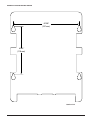
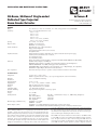
I56-3433-001R
INSTALLATION AND MAINTENANCE INSTRUCTIONS
SK-Beam, SK-Beam-T Single-ended
Reflected Type Projected
Beam Smoke Detector
Specifications
General
Range:
Sensitivity:
Spacing:
Response Time:
Trouble Conditions:
Test/Reset Features:
Indicators:
Style 7 Operation:
Environmental
Temperature:
Humidity:
Mechanical
Shipping Weight:
Shipping Size:
Mounting:
Wiring:
Adjustment Angle:
Paintable Trim Ring:
Electrical
Voltage:
Standby Current:
External Supply (SK-Beam-T only):
Remote Output: (alarm)
16 to 230 Feet (5 to 70m); 230 to 328 Feet (70 to 100m) using optional accessory BEAMLRK
25% to 50% Total Obscuration in 6 levels
Level 1 = 25%
Level 2 = 30%
Level 3 = 40%
Level 4 = 50%
Level 5 = 30% to 50% (Acclimate)
Level 6 = 40% to 50% (Acclimate)
30 to 60 Feet (9.1 to 18.3m)
Alarm - 20 seconds typical
Trouble - 30 seconds typical
Beam Blockage (96% or More Obscuration)
Improper Initial Alignment
Self-compensation limit reached (service needed)
In Alignment mode
Integral Sensitivity Test Filter (SK-Beam-T only, requires additional external power supply)
Sensitivity Filter (Incremental scale on reflector)
Local Alarm Test Switch
Local Alarm Reset Switch
Remote Test and Reset Switch Capability (compatible with RTS451/RTS451KEY/RTS151/RTS151KEY)
Alarm - Remote Output, Local LED (red)
Trouble - Remote Output, Local LED (yellow) Blink Pattern Indicates Trouble Diagnostics
Normal Operation - Local LED (flashing green with communication)
Alignment Aids - Optical Gunsight (coarse adjustment) 00 to 99 Digital Display (fine adjustment)
Sensitivity - Digital Display Readout in Percent Obscuration
On-board isolators provide style 7 operation. (may be disabled via shunts on circuit board)
–22°F to 131°F (–30°C to 55°C);
Note: for applications below 32°F (0°C) see Special Applications section of this manual.
10% to 93% RH Noncondensing
3.9 lbs. (1.77 kg)
15˝ × 10.5˝ × 6.5˝ (381mm × 267mm × 165mm)
Wall only without optional accessories
Plug-in Terminal Blocks (12 to 22AWG)
±10° Horizontal and Vertical
May be painted using enamel or acrylic type paints
15 to 32 VDC
Avg. Standby:
2mA Max. (1 communication every 5 sec., LED flashing, SLC @ 24 V)
Max. Alarm (LED on):
8.5mA Max.
Max. Trouble (LED on):
4.5mA Max.
Max. Alignment:
20mA Max.
Voltage - 15 to 32 VDC
Current - 0.5A Max.
Voltage - 15 to 32 VDC; Note: Output voltage same as device input voltage.
Current - 15mA maximum; 6mA minimum; Note: Output current is limited by 2.2Kohm resistor
tector are compensated for by a microcontroller that continuously monitors
the signal strength and periodically updates the alarm and trouble thresholds. When the self-compensation circuit reaches its limit, the detector generates a trouble signal, indicating the need for service.
General Description
Model SK-Beam/SK-Beam-T is a long range projected beam smoke detector
designed to provide open area protection. It is to be used with UL-listed compatible control panels only. The detector consists of a transmitter/receiver unit
and a reflector. Smoke entering the area between the transmitter/receiver and
reflector causes a reduction in signal. When the obscuration reaches alarm
thresholds (chosen at the transmitter/receiver unit), the detector generates
an alarm signal. Complete blockage of the beam causes a trouble signal. Slow
changes in obscuration due to a build up of dirt or dust on the lens of the deSK-400-007
12 Clintonville Road, Northford, CT 06472
203.484.7161; Fax: 203.484.7118
www.silentknight.com
Three LEDs on the detector indicate the current status: a red LED for alarm,
a yellow LED for trouble, and a blinking green LED for standby operation.
Note: The panel controls the status of the red and green LEDs. The local
reset button is accessible by removing the outer paintable trim ring. The
yellow LED will blink in specific patterns to provide a diagnostic aid when
1
I56-3433-001R
BEAMHKR
diagnosing the cause of a trouble signal. It will also blink the amount of drift
compensation that has been used at the conclusion of the test. Trouble signals
automatically reset upon removing the cause of trouble. Red and yellow LEDs
can be remotely connected to the remote Alarm and Trouble outputs. These
outputs mimic the functions of the detector’s red and yellow LEDs. In addition
to these indicators, there is a dual digital display that reads 00 to 99. This display is used to indicate the signal strength of the beam in alignment mode and
to indicate the sensitivity setting of the detector in percent obscuration when
setting the sensitivity of the detector. No additional equipment is needed for
alignment of the beam.
The BEAMHKR allows the reflector to operate in environments prone to the
formation of condensation. Condensation forming on the reflector may result in trouble or false alarm conditions. BEAMHKR will lessen the likelihood
of condensation by maintaining the reflector at a temperature that is slightly
higher than surrounding air. The kit requires a 24V power supply. When used
with the long-range reflector kit (BEAMLRK), it is necessary to purchase and
install four BEAMHKR kits. Please refer to the BEAMHKR installation manual
for operation instructions.
RTS451/RTS451KEY/RTS151/RTS151KEY
Special Applications
Due to the inherent capabilities of projected type beam detectors they are often
installed in locations where spot-type detection is impractical. Projected type
beam smoke detectors are ideally suited for environmental conditions that
might include high ceilings, dusty and dirty environments, or environments
that experience temperature extremes. Often these conditions present special
problems for the installation of spot-type detectors and even greater problems
for their proper maintenance. Due to the inherent flexibility of mounting locations and large coverage area of projected type beam detectors often the conditions above can be addressed or minimized.
The remote test accessory, RTS451/RTS451KEY or RTS151/RTS151KEY, allows
for the beam detector to be tested remotely. The test accessory provides test and
reset functions and green and red LED’s that mimic the LEDs on the detector.
Parts List
Description
Quantity
Transmitter/Receiver Unit. . . . . . . . . . . . . . . . . . . . . . . . . . . . . . . . . . . . . 1
Paintable Trim Ring. . . . . . . . . . . . . . . . . . . . . . . . . . . . . . . . . . . . . . . . . 1
Reflector . . . . . . . . . . . . . . . . . . . . . . . . . . . . . . . . . . . . . . . . . . . . . . 1
Plug-in Terminal Blocks. . . . . . . . . . . . . . . . . . . . . . . . . . . . . . . . . . . . . . 3
Isolator Shunts . . . . . . . . . . . . . . . . . . . . . . . . . . . . . . . . . . . . . . . . . . . . 2
Instruction Manual . . . . . . . . . . . . . . . . . . . . . . . . . . . . . . . . . . . . . . . . . 1
Orange Sticky Paper. . . . . . . . . . . . . . . . . . . . . . . . . . . . . . . . . . . . . . . . . 1
Parts Diagram (not to scale)
Some examples of applications for beam detectors might include freezers, aircraft hangars, cold storage warehouses, shipping warehouses, enclosed parking facilities, sporting arenas and stadiums, concert halls, barns, or stables.
Some of these environments might be considered too hostile for spot-type
smoke detectors. If the environment is considered to be hostile then the colder
alarm threshold settings should be used.
TERMINAL BLOCK
Before installing the transmitter/receiver unit or reflector in these types of
applications special consideration should be given to insure proper operation
of the beam detector. The beam detector should not be installed in environments where there is no temperature control and condensation or icing is
likely. Condensation or icing of the reflector surface or the outer surface of
the transmitter/receiver unit will obscure the light beam resulting in a false
alarm. If elevated humidity levels and rapidly changing temperatures can be
expected then condensation will likely form and the application should not be
considered acceptable for the beam detector.
ISOLATOR
SHUNT
Approved Accessories
The following accessories can be purchased separately for use with this beam
detector.
C0306-00
Detector Placement
This section of the manual discusses the placement of projected beam detectors. Though this information is based upon industry expertise, it is intended
to be used only as a technical guide. Always comply with the requirements of
applicable codes and standards such as, NFPA 72, National Fire Alarm Code,
as well as directives of the Authority Having Jurisdiction (AHJ).
BEAMLRK
The BEAMLRK allows Silent Knight reflected beam detectors to be installed at
separations between 230 and 328 feet (70 to 100 meters). At these distances,
four 8˝ × 8˝ reflectors must be used to provide enough reflected infrared light.
This kit includes 3 additional reflectors with new test scale legends. The reflector included with the transmitter/receiver unit is the fourth reflector to be
used. This kit is not compatible with the multi-mount kit (BEAMMMK).
Projected beam detectors are usually located with their beams parallel to the
ceiling. However, they can be mounted vertically or at any angle to protect the
area involved. Since beam detectors sense the smoke buildup over a distance,
they are ideal for locations with high ceilings. They can also be mounted on a
wall or ceiling below the level of a spot type detector, reducing the effects of
air stratification. Some typical locations would include large areas with high
ceilings such as atriums, warehouses, and factories.
BEAMMMK
The BEAMMMK allows Silent Knight reflected beam detectors and reflectors
to be mounted to either a vertical wall or the ceiling. The kit allows for additional alignment range in cases where the detector and reflector cannot be
mounted within 10° of each other. The kit includes the hardware necessary
to mount either a single transmitter/receiver unit or a single reflector. (To
mount the transmitter/receiver the surface mount kit, BEAMSMK, must also
be used). If the transmitter/receiver and the reflector require additional alignment range two kits are required. The kit is not compatible with the longrange reflector kit (BEAMLRK).
NOTE: Projected beam smoke detectors should always be mounted to stable mounting surfaces. See the MOUNTING LOCATION section for details.
Some fire codes specify spacing on a given center-to-center distance between
detectors under ideal conditions. This spacing is based on rooms with smooth
ceilings and no physical obstructions between the contents being protected
and the detectors. Moreover, they are also based on a maximum ceiling height,
and on the assumption that the value and the combustible nature of the contents of the room being protected do not warrant greater protection or closer
spacing.
BEAMSMK
The BEAMSMK allows Silent Knight reflected beam detectors to be mounted
when surface wiring is used. This kit must be used when mounting the transmitter/receiver unit with the multi-mount kit (BEAMMMK).
In a room with a smooth ceiling, detectors should be spaced between 30 and
60 feet (9.1 to 18.3m). One-half that spacing between the beam and the sidewall may be used as a guide. See Figure 1. The beam detector can be mounted
with the transmitter/receiver on one wall and the reflector on the opposite
wall, or both suspended from the ceiling, or any wall/ceiling combination.
In the case of the ceiling mount, the distance from the end walls should not
exceed one-quarter of the selected spacing (7.5 ft. [2.3m] maximum if the
spacing is 30 ft. [9.1m]). See Figure 2.
BEAMHK
The BEAMHK allows the transmitter/receiver unit to operate in environments
prone to the formation of condensation. Condensation forming on the beam
detector unit may result in trouble or false alarm conditions. BEAMHK will
lessen the likelihood of condensation by maintaining the unit at a temperature
that is slightly higher than the surrounding air. Please refer to the BEAMHK
installation manual for operation instructions.
SK-400-007
PAINTABLE TRIM RING
2
I56-3433-001R
Figure 1. Spacing for smooth ceiling (side view):
/ S
Figure 4. Sloped ceiling (peaked type):
S
1 2
MOUNT DETECTOR
ANYWHERE IN
THIS AREA
12 - 18 IN.
(0.3 - 0.46M)
REFLECTOR
Tx/Rx
1
/2 S
S
3 FT.
(0.9
MAX. M)
WALL
S
1
/2 S
3 FT.
(0.9
MAX. M)
C0254-00
C0257-00
Figure 2. Spacing for smooth ceiling (top view):
Mounting Locations
Beam detectors require a stable mounting surface for proper operation. A surface that moves, shifts, vibrates, or warps over time will cause false alarm or
trouble conditions. Initial selection of a proper mounting surface will eliminate false alarms and nuisance trouble signals.
/ S MAXIMUM
1 2
Tx/Rx
REFLECTOR
/ S
MAX.
1 4
Mount the detector on a stable mounting surface, such as brick, concrete,
a sturdy load-bearing wall, support column, structural beam, or other surface that is not expected to experience vibration or movement over time. DO
NOT MOUNT the beam detector on corrugated metal walls, sheet metal walls,
external building sheathing, external siding, suspended ceilings, steel web
trusses, rafters, nonstructural beam, joists, or other such surfaces.
S
Tx/Rx
In cases where only one stable mounting surface as defined above can be used,
the transmitter/receiver unit should be mounted to the stable surface and the
reflector should be mounted to the less stable surface. The reflector has a
much greater tolerance for the unstable mounting locations defined above.
REFLECTOR
16 FT. (5M) MINIMUM
328 FT. (100M) MAXIMUM
Mounting Instructions
The transmitter/receiver unit may be mounted over a recessed junction box.
The cavity behind the detector is then used for routing of the wiring from the
junction box to the terminal blocks on the detector. The transmitter/receiver
unit should be mounted to the wall such that unit covers the recessed junction box in the wall completely. If the junction box is not recessed then you
may use the surface mount kit (BEAMSMK). See the BEAMSMK installation
instructions for surface mounting instructions. The transmitter/receiver unit
can be mounted to the wall using the supplied drilling template (see Appendix
II). The detector base has 4 primary mounting keyholes, one in each corner of
the base. All four hole locations should be used to provide a secure mounting.
The outer housing of the beam detector is held to the base using four screws.
In order to mount the detector you must remove the outer housing first.
C0255-00
In the case of peaked or sloped ceilings, codes may specify spacing of detectors by using horizontal spacing from the peak of the roof or ceiling. Figures
3 and 4 show the spacing for both the shed type and peaked type sloped
ceilings.
On smooth ceilings, beam smoke detectors should generally be mounted between 12 and 18 inches (0.3 to 0.46m) from the ceiling. In many cases, however, the location and sensitivity of the detectors shall be the result of an
engineering evaluation that includes the following: structural features, size
and shape of the room and bays, occupancy and uses of the area, ceiling
height, ceiling shape, surface and obstructions, ventilation, ambient environment, burning characteristics of the combustible materials present, and the
configuration of the contents in the area to be protected.
The reflector can be mounted to the wall using the supplied drilling template
(see Appendix III). The reflector has 4 mounting holes, one in each corner.
All four hole locations should be used to provide a secure mounting. The
reflector must be mounted such that it is within 10° in both the X and Y
planes of the transmitter/receiver unit. See Figure 5a. The reflector must also
be mounted such that plane of the reflector is perpendicular to the optical
line of sight to the transmitter/receiver unit. The maximum tolerance for nonperpendicular mounting locations is 10°. See Figure 5b. If the reflector cannot
be mounted within 10° of the transmitter/receiver unit then the multi-mount
kit (BEAMMMK) may be used to provide greater angular adjustment of the
transmitter/receiver unit. If the perpendicular plane of the reflector cannot be
mounted within 10° of the optical line of sight then the multi-mount kit can be
used for the reflector. See BEAMMMK instructions.
Figure 3. Sloped ceiling (shed type):
3F
(0.9M T.
)MAX
.
S
S
1
REFLECTOR
/2 S M
AX.
Tx/Rx
To aid in locating the reflector in the alignment mirror at long distances a
bright orange sticky backed piece of paper is provided. Remove the protective
backing from the orange sticker. Temporarily affix the orange paper next to
the reflector using the sticky backing of the paper. The location of the sticky
paper is not critical. It may be placed anywhere near the reflector as long as it
not covering the reflective surface of the reflector. This sticky paper should be
removed once the installation is completed.
C0256-00
SK-400-007
3
I56-3433-001R
Figure 5a. Reflector Mounting Guidelines
Wiring Installation Guidelines
Always install all wiring in compliance with the National Electrical Code, and/
or the applicable local codes, and any special requirements of the local authority having jurisdiction. Proper wire gauges and suitable means for strain
relief should be used. The conductors used to connect beam smoke detectors
to control panels and accessory devices should be color-coded to reduce the
likelihood of wiring errors. Improper connections can prevent a system from
responding properly in the event of a fire.
L
L
WA
10
OR
CT
10
Installation wire used for the beam detector shall be no smaller than 22 AWG
(1.0 mm2). For best system performance, all wiring should be twisted pair and
installed in separate grounded conduit. Do NOT mix fire system wiring in the
same conduit as any other electrical wiring. Shielded cable may be used to
provide additional protection against electrical interference.
E
FL
RE
When installing the beam smoke detector in applications where the head
unit will be mounted to either a wall or the ceiling using the multi-mount kit
(BEAMMMK) flexible conduit will be used. The surface mount kit (BEAMSMK)
and multi-mount kit (BEAMMMK) must be installed with the cable before wiring the unit, according to the instructions supplied with the kit.
ACCEPTABLE MOUNTING
LOCATIONS FOR REFLECTOR
C0258-00
When the detector has been mounted over a recessed junction box, all wiring
should be routed out of the box and behind the detector to the bottom of the
detector where the terminal blocks are located. When installing the wiring
in the junction box be sure to leave enough wire in the box to connect to the
terminal blocks. (Approximately 9˝ (23cm) of wire outside of the junction box
will be required for proper installation). All wiring to the detector is done via
pluggable terminal blocks. In order to properly make electrical connections
strip approximately 1/4˝ (6mm) of insulation from the end of the wire, sliding
the bare end of the wire under the clamping plate screw.
Figure 5b. Reflector Mounting Guidelines
10 MAXIMUM
OPTICAL LINE OF SIGHT
Figure 6 shows all the wiring connections to the transmitter/receiver unit.
Figure 7 shows the proper wiring diagram for either class A or class B operation. Figure 8 shows the connections that are necessary when using one of
the optional remote test stations (RTS451/RTS151 or RTS451KEY/RTS151KEY).
Figure 9 shows the remote output for alarm indication.
REFLECTOR
C0259-00
Mounting Considerations for Single Ended Beam Detectors
There must be a permanent clear line of vision between the detector and the
reflector. Reflective objects must not be near the line of vision between the
detector and reflector. Reflective objects too near to the line of sight can reflect
the light beam from the transmitter to the receiver. If this occurs, the detector
will not be able to distinguish these reflections from those of the reflector and
the protected space will be compromised. Reflective objects should be a minimum of 15 inches (38.1cm) from the line of sight between the detector and
reflector. In cases where reflective objects cannot be avoided, the complete reflector blockage test can be used to determine if the installation is acceptable.
See Testing and Maintenance Section of this manual.
WARNING: Disable the zone or system before applying power to the beam
detector to prevent unwanted alarms. When applying power to
the beam detector before the alignment procedure has been completed the detector may enter alarm or fault.
Light sources of extreme intensity such as sunlight and halogen lamps, if directed at the receiver, can cause a dramatic signal change resulting in fault
and alarm signals. To prevent this problem direct sunlight into the transmitter/
receiver unit should be avoided. There should be a minimum of 10° between
the pathway of the light source and detector and the line of sight between
detector and reflector.
Operation of the detector through panes of glass should be avoided. Since
single ended beam detectors operate on a reflection principle, a pane of glass
perpendicular to the line of sight between the detector and the reflector can
reflect the light beam from the transmitter to the receiver. If this occurs, the
detector will not be able to distinguish these reflections from those of the reflector and the protected space will be compromised.
Panes of glass will also absorb some of the light as it passes through it. This
absorption of light will reduce the acceptable installed distance between the
detector and the reflector.
In cases where operation through panes of glass cannot be avoided some specific installation practices can help to minimize the effects of the glass. These
practices include: avoid penetration of multiple panes of glass, position the
glass so that it is not perpendicular to the line of sight between the detector
and the reflector, (A minimum of 10° off perpendicular should be considered),
and make certain that the glass is smooth, clear and mounted securely. The
complete reflector blockage test can be used to determine if the installation is
acceptable. See Testing and Maintenance Section of this manual.
Where high ceilings (in excess of 30 feet or 9.1 meters) are present additional
beams may be required to detect smoke at lower levels.
SK-400-007
4
I56-3433-001R
Figure 6. Wiring Connections at Detector
Figure 8. Wiring Diagram (RTS451/RTS151)
DETECTOR
PIN 1
PIN 2
PIN 4
PIN 3
PIN 5
RTS451/RTS451KEY
or RTS151/RTS151KEY
T1-1 SLC IN +
SLC OUT + T1-3
T1-2 SLC IN –
SLC OUT – T1-4
T2-1 REMOTE ALARM OUT
T2-2 AUX (–)
T2-4 RESET INPUT
T2-3
TEST INPUT
T3-3
REMOTE TROUBLE OUTPUT
OPTIONAL YELLOW LED
C0328-06
Figure 9. Wiring Diagram (RTS451/RTS151)
BDT-SS
SLC (+)
T3
T2
Alarm
Signal
Circuit
(Note 1)
T1
T2-1
SLC (–)
SLC (+)
SLC (–)
SLC (+)
RESET I NPUT
TEST INPUT
AUX (–)
REMOTE ALARM OUT
NOT USED
REMOTE TROUBLE OUT
TEST OPTION (–)
TEST OPTION (+)
Red
T2-2
SLC (–)
Note 1: See electrical ratings section of this
manual for circuit output ratings.
C0260-01
C0369-00
Installation / Alignment
Reference Figures 10 through 14 for installation, alignment, and maintenance.
Figure 7. Wiring Diagram
The alignment of the SK-Beam/SK-Beam-T is divided into four steps: coarse
alignment, fine adjustment, final gain adjustment, and final verification. It is
necessary for all four steps to be executed properly to ensure proper alignment
of the product. If the detector and reflector are mounted per Mounting Locations and Mounting Instructions sections of this manual and the alignment
procedures are executed properly, false alarms and nuisance trouble signals
will be minimized.
Pre-Alignment Checklist
• Insure that both the detector and reflector are mounted securely to stable
surfaces.
• Insure that all wiring is correct.
• Insure that terminal blocks are fully seated into their receptacles on the
detector.
• Complete
any wiring dressing to minimize movement to the detector once
the alignment procedure is completed.
T3
LISTED
REMOTE
POWER
SOURCE
* Only used for
SK-BEAM-T. See
electrical ratings.
+
T2
ñ
• Insure
that the appropriate number of reflectors are used for the installed
distance. Distances between 230 and 328 Feet (70 – 100m) require additional reflectors (4 total). The BEAMLRK accessory should be used in
these cases.
T1
+ ñ
+
ñ
ñ
+
FROM PANEL OR
PREVIOUS DEVICE
• Insure that the line of sight between the detector and reflector is clear
and that reflective objects are not too near. See Mounting Instructions
for more details.
+ ñ
COMMUNICATION LINE
32 VDC MAX.
TWISTED PAIR IS
RECOMMENDED.
TO NEXT
DEVICE
• Insure that both the detector and reflector are mounted within their
operational parameters for off axis angles. See Mounting Instructions
for more details.
C0335-03
• D
isable the zone or system to prevent unwanted alarms before applying
power.
• Insure power to the detector is “ON”.
• I nsure that the appropriate address is set on the code wheels.
You are now ready to begin the alignment procedure.
SK-400-007
5
I56-3433-001R
Step 1. Coarse Alignment
Refer to Figures 11 and 12 for this step.
NOTE: The alignment procedure is not complete yet.
At this time it is possible to set the sensitivity of the detector using the sensitivity switch and digital display. See the Sensitivity Selection section of this
manual for further details.
1.Insure that both of the optics lock-down screws are loosened so that the
optics will move freely.
2.Looking through the alignment mirror at both the alignment sight and
reflector simultaneously locate the position of the reflector in the optical
sight. This step will require some practice. It is necessary to train your
eyes to shift focus between the reflector and the mirror in order to locate
the reflector. If the distance between the reflector and the detector is
large it is helpful to place a brightly colored object on the wall near the
reflector to aide in seeing the reflector in the alignment mirror.
3.Once the reflector has been located, begin to adjust both the horizontal
and vertical alignment knobs so that the reflector becomes centered in
the alignment mirror. Take care in this step. If the optics are incorrectly
aligned in this step, it will not be possible to proceed with the fine adjustment step.
Step 2. Fine Adjustment
Refer to Figures 10 through 12 for this step.
Step 3. Final Gain Adjustment
Refer to Figure 13 for this step.
In this step, the detector will electronically adjust its internal gain one final
time. It is necessary to complete this step with the outer housing installed
since the housing will change the amount of light received from the reflector.
1.Tighten the optics lock down screws so the optics are secure.
2.Install the outer housing of the detector. The housing is installed by tightening four screws, one in each corner of the housing. The screws are captivated in the plastic of the housing and cannot fall out during assembly.
NOTE: The housing contains a gasket seal that protects the detector circuitry
from corrosion and moisture sources. To insure that the gasket seal performs
correctly it is necessary to fully tighten all four of the screws that hold the
outer housing in place.
3.Remove the protective film from the front surface of the outer housing.
4.To initiate the final electronic gain adjustment, the reset switch must
be depressed. Once depressed the yellow LED will begin to blink. This
indicates that the detector is adjusting the electronic gain setting. Once
complete, the yellow LED will stop blinking and the green LED will begin
blinking. This indicates that the gain adjustment was successful.
NOTE: Use caution not to block the line of sight between the detector and
reflector in this step.
5.Install the outer aesthetic ring by snapping it onto the outer housing.
NOTE: If the outer aesthetic ring has been painted insure that the paint is
completely dry before proceeding with this step.
Step 4. Final Verification
This step is required to insure the detector has been setup correctly and will
detect smoke at the proper sensitivity level.
In this step you will be fine-tuning the optics to the reflector. To provide feedback of the signal level coming from the reflector the dual digital display readout will be used. Due to the large distance range that the detector can operate
over it is necessary that the detector operate with many different settings of
“electronic amplifier gain”. The detector is capable of determining the appropriate gain setting and then setting it itself via on-board processing algorithms.
There are no external gain settings on the detector that must be set by the
operator. Periodically throughout the fine adjustment step the detector will
need to re-adjust its “electronic amplifier gain” setting. When this occurs it
will be indicated by the dual digital readout as “- -”. When this occurs, cease
any further adjustment until the display again reads a number value.
1.Insure that neither you nor any other objects are in the line of sight between the detector and the reflector.
2.Depress the Alignment switch once. Both the digital display and the yellow LED should turn on indicating that alignment mode has been entered. The display should begin reading “- -” signifying an electronic gain
adjustment. After a few moments the display will indicate a numeric
value near 20. If the display reads “Lo” then the detector is not receiving
enough light from the reflector. Go back and repeat the course alignment
step and verify that the proper number of reflectors is used for the installed distance.
NOTE: The display will continue to read “Lo” until the detector receives
enough light from the reflector to continue with the fine adjustment step.
NOTE: In alignment mode (indicated by the yellow LED and the numeric display) the sensitivity select and test switches are disabled.
3.With the display reading a numeric value, begin adjusting the horizontal
and vertical alignment knobs one at a time in the direction that increases
the numeric signal level on the display. Continue adjusting each axis
one at a time going back and forth between them until a peak value is
indicated. If a value of 90 is achieved, the detector will re-adjust the electronic gain once again. This will be indicated by a “- -” reading on the
display. When this happens halt any further adjustment until the display
again reads a numeric value. This process may occur more than once
during the fine adjustment step.
NOTE: Each time the display reads a value of 90 or greater the detector will
reduce the electronic gain. Each time the display reads a value of 10 or less the
detector will increase the electronic gain.
4.Once satisfied that it is not possible to achieve a higher reading on the
display depress the alignment switch to complete the fine adjustment
step. The digital display readout will turn “OFF” and the yellow LED will
remain “ON”.
NOTE: It may not be possible to achieve a value near 90 on the display during
the last adjustment iteration. The final value of the display will not likely be
near 90. This is normal. It is due to the detector reducing its electronic gain
each time a value of 90 is achieved. When this occurs the detector resumes
with less electronic gain than previously when 90 was achieved. Less gain
makes it more difficult to achieve higher values. Final values anywhere between 20 and 90 are acceptable if no further increase can be achieved.
SK-400-007
1.With the detector functioning (indicated by the green LED blinking),
completely block the reflector with an opaque material. (Due to the high
optical efficiency of the reflector the selection of the opaque material
used to block the reflector is not critical. Acceptable materials include,
but aren’t limited to, this manual or the cardboard packaging inserts.)
See Figure 14. The detector should enter the fault condition (indicated by
the fault relay and the yellow LED (see Appendix I). If the detector does
not enter the trouble condition there is a problem with the installation
refer to the troubleshooting section in Appendix I for further assistance.
2.Complete a sensitivity test of the detector. Refer to the Sensitivity Testing
section of this manual for the appropriate procedure.
3. If the orange sticky paper was used to aid in the location of the reflector in
the alignment mirror it should be removed now. It is no longer necessary.
Congratulations. You have completed the final installation and alignment
procedure.
6
I56-3433-001R
Figure 10. Switch Locations
Figure 12. Coarse Alignment Procedure
EYE
!,)'.-%.4
3%.3)4)6)49
REFLECTOR
#/$%37)4#(
4%.3 /.%3
4%34
C0265-00
Figure 13. Housing Screw Locations
2%3%4
SCREW LOCATIONS
349,%)3/,!4/23(5.43
3(/7.$)3!",%$
C0854-00
Figure 11. Alignment Adjustment Locations
ALIGNMENT
POSITION
INDICATOR
ALIGNMENT MIRROR
ALIGNMENT GUNSIGHT
DIGITAL SIGNAL
STRENGTH
READOUT
RESET SWITCH
C0266-00
Short Circuit Isolation
The detector includes an on-board circuit isolator that allows for NFPA72 style
7 operation. In cases where style 7 operation is not desired the isolator can be
disabled using the two shunts on the circuit board. See Figure 10 for jumper
locations. When the jumpers are present the isolator is disabled. This is the
default state.
HORIZONTAL
ADJUSTMENT
OPTICS
LOCK-DOWN
SCREWS
VERTICAL
ADJUSTMENT
SK-400-007
Sensitivity Selection
The detector has six sensitivity selections. Each of these selections is only
acceptable over a specific distance separation between the detector and the
reflector per UL268. The chart below is used to determine which selections are
acceptable for your installed distance. The sensitivity of the detector can be
set only when the housing is removed and the detector is not in the fine adjustment step of the alignment mode, indicated by the illumination of the dual
digital display. To set the sensitivity depress the sensitivity button one time.
See Figure 10. Once the switch is pressed the digital display will illuminate
and read the current sensitivity setting in percent obscuration. To change the
sensitivity continue to depress the sensitivity switch until the desired setting
is achieved. The digital display will turn off automatically if no further switch
presses occur.
C0264-00
7
I56-3433-001R
Sensitivity
Setting
%
Obscuration
Display
Reading
Acceptable
Distance
Between
Detector
and
Reflector
(Feet)
Figure 14. Reflector Test Card Procedure
Acceptable
Distance
Between
Detector and
Reflector
(meters)
Level 1
25
25
16.4 to 120
5.0 to 36.6
Level 2
30
30
25 to 150
7.6 to 45.7
Level 3
40
40
60 to 220
18.3 to 67
Level 4
50
50
80 to 328
24.4 to 100
Acclimate
Level 1
30 to 50
A1
80 to 150
24.4 to 45.7
Acclimate
Level 2
40 to 50
A2
80 to 220
24.4 to 67
LINE UP EDGE OF
TEST CARD WITH
APPROPRIATE
OBSCURATION LEVEL
In addition to the four standard sensitivity selections the detector has two Acclimate settings. When either of these settings is chosen the detector will automatically adjust its sensitivity using advanced software algorithms to select
the optimum sensitivity for the environment. The sensitivity will be continuously adjusted within the ranges specified in the chart above.
MOVE TEST CARD TO DESIRED AMOUNT OF OBSCURATION
C0267-00
Sensitivity
Total obscuration can be converted to percent per foot, assuming uniform
smoke density for the entire length of the beam. The charts below converts
4.The detector can be reset with the reset switch on the detector unit or
remote reset.
5.Notify the proper authorities that the system is back on line.
If the detector fails this test several steps should be taken to determine if the
detector is faulty or simply needs to be re-adjusted before returning the unit.
These steps include:
total obscuration to percent per foot for all acceptable sensitivity settings.
SENSITIVITY IN PERCENT PER FOOT VS. DISTANCE
OBSCURATION (%/FT.)
(ASSUMES UNIFORM SMOKE DISTRIBUTION)
2.0
1.Verify all wiring connections and appropriate power is applied to the
detector.
2.Verify that the optical line of sight is free from obstructions and reflective
objects.
3.Apply the maintenance procedure in this manual. Repeat the test procedure. If the detector still fails the test procedure proceed with step 4.
4.Repeat the alignment procedure in this manual. If the alignment procedure is successful repeat the test procedure. If the detector still fails
the test it should be returned.
NOTE: For the SK-Beam-T the external power supply must be connected for
the test switch to work.
B. Test Switch
The detector can be tested using the local test switch on the transmitter/receiver unit or remotely using the remote test station.
30% SETTING
1.5
40% SETTING
1.0
50% SETTING
0.5
0.0
25% SETTING
0
50
100
150
200
DISTANCE IN FEET
250
300
350
C0268-00
Sensitivity Testing
NOTE: Before testing, notify the proper authorities that the smoke detector
system is undergoing maintenance, and therefore the system will be temporarily out of service. Disable the zone or system undergoing maintenance to
prevent unwanted alarms.
Detectors must be tested after installation and following periodic maintenance.
The sensitivity of the SK-Beam/SK-Beam-T may be tested as follows:
The remote test station, RTS451/RTS151 or RTS451KEY/RTS151KEY, can be
used with the SK-Beam/SK-Beam-T beam smoke detector. Follow instructions
included with the test station for proper use. See Figure 8 (Remote Test Station) for wiring diagram.
NOTE: Before testing the detector, check for the presence of the flashing green
LED at the receiver, making sure not to disturb or block the beam. If it does
not flash and the detector is not in trouble or alarm, power has been lost to
the detector (check the wiring).
A. Calibrated Test Filter
The sensitivity of the detector can be tested using an opaque material to cover
the reflector by an amount indicated by the graduated scale on the reflector.
(Due to the high optical efficiency of the reflector the selection of the opaque
material used to block the reflector is not critical. Acceptable materials include, but aren’t limited to, this manual or the cardboard packaging inserts.)
The SK-Beam-T is equipped with an integral sensitivity test feature that consists of a calibrated test filter attached to a servo motor inside the detector
optics. When a test is initiated using the remote test station or local test switch
the test filter is moved in the pathway of the light beam. The on-board microprocessor then determines if the proper level of signal reduction is received at
the receiver. If the proper level of signal reduction is received the detector will
enter alarm. If the proper level of signal reduction was not achieved, indicating that the sensitivity of the detector is out of tolerance, the detector will
enter the trouble condition.
Refer to Figure 14 for this procedure.
Always perform a complete reflector blockage test as in step 4 of the Installation/Alignment procedure to insure that the pathway between the detector
and reflector is clear.
1.Verify the sensitivity setting of the detector in % obscuration. See the
Sensitivity Selection section of this manual for sensitivity determination
if sensitivity is unknown.
2.Place the blocking material over the reflector, lining it up with the graduated marks that are 10 less than the detector’s setting in % obscuration.
The detector should not alarm or fault. Keep the material in place for a
minimum of 1 minute.
3.Place the blocking material over the reflector lining it up with the graduated marks that are 10 more than the detectors setting in % obscuration.
The detector should enter alarm within 1 minute.
SK-400-007
NOTE: For the SK-Beam this test does not satisfy the requirements of NFPA72
for periodic maintenance and sensitivity verification of beam type detectors.
For the SK-Beam-T this test in conjunction with the complete reflector blockage test (see step 4 of the Installation/Alignment procedure in this manual)
does satisfy the requirements of NFPA72 for periodic maintenance and sensitivity verification of beam type detectors.
If the detector fails this test several steps should be taken to determine if the
detector is faulty or simply needs to be re-adjusted before returning the unit.
8
I56-3433-001R
These steps include:
1.Verify all wiring connections and appropriate power is applied to the
detector.
2.Verify that the optical line of sight is free from obstructions and reflective
objects.
3.Apply the maintenance procedure in this manual. Repeat the test procedure. If the detector still fails the test procedure proceed with step 4.
4.Repeat the alignment procedure in this manual. If the alignment procedure is successful repeat the test procedure. If the detector still fails the
test it should be returned for repair.
NOTE: For the SK-Beam-T, the external power supply must be connected for
the test switch to work.
Maintenance
NOTE: Before cleaning the detector, notify the proper authorities that the
smoke detector system is undergoing maintenance, and therefore the system
will be temporarily out of service. Disable the zone or system undergoing
maintenance to prevent unwanted alarms.
1. Carefully clean the outer housing lens face. A damp soft cloth with a mild
soap may be used. Avoid products with solvents or ammonia.
2. Carefully clean the reflector. A damp soft cloth with a mild soap may be
used. Avoid products with solvents or ammonia.
3. Notify the proper authorities that the system is back on line.
Painting
The outer aesthetic ring may be painted using a spray or brush type paint of
appropriate type. See specification section of this manual for paint types.
NOTE: Never paint the flat lens surface of the outer housing.
Special Note Regarding Smoke Detector Guards
Smoke detectors are not to be used with detector guards unless the combination has been evaluated and found suitable for that purpose.
SK-400-007
9
I56-3433-001R
Appendix I. Operation Modes and Troubleshooting Guide
Normal
Yellow,
*Red
Remote
See
Trouble
Note
Below
Off
Off
Dual Digital Display
*Green Remote
Alarm
See
Note
Below
Blink
Blink
Off
Alignment
Off
On
Blink
Alarm
On
Off
Off
Trouble-Drift
Comp Elevated
Signal
Trouble-Drift
Comp Reduced
Signal
Off
3 Quick
Blinks
Blink
Blink
Off
Long Term Drift Reference Out
of Range
• Sunlight into detector or reflector.
• Re-Align detector.
Off
2 Quick
Blinks
Blink
Blink
Off
Long Term Drift Reference Out
of Range
• Clean detector and reflector.
Trouble-Signal
Over Range
Off
2 Quick
Blinks
Blink
Blink
Off
Increase of Reflected Signal
• Inspect line of sight between detector and
reflector for reflective objects in the pathway.
Trouble-Beam
Blockage
Response
InitializationPower on
Off
4 Quick
Blinks
Blink
Blink
Off
Beam Blockage
• Remove blockage.
• Faulty unit.
Off
Blink until
complete
Blink
Blink
Off
Apply Power from discharged
state.
Initializationalignment exit
Off
Blink until
complete
Blink
Blink
Off
Depressing RESET switch after
alignment
Local Test
(SK-Beam-T)
Pass Result
On
Off
On
Off
Panel or RTS451, RTS451KEY, Remains in alarm until reset or time-out
RTS151, or RTS151KEY
Local Test
(SK-Beam-T)
Fail Result
Local Test
(SK-Beam)
Fail
Local Test
(SK-Beam)
Pass Result
Off
Blinking
the
amount of
drift used
On until
reset or
time-out
On until
reset or
time-out
Blinking
the
amount of
drift used
Blink
Blink
Off
Panel or RTS451, RTS451KEY,
Remains in fault until reset or time-out
RTS151, or RTS151KEY test input
Blink
Blink
Off
Panel or RTS451, RTS451KEY,
Remains in fault until reset or time-out
RTS151, or RTS151KEY test input
On
Off
Panel or RTS451, RTS451KEY, Remains in alarm until reset or time-out
RTS151, or RTS151KEY
Modes
Off
On
Off
Blink
On
Initiating means
Comments & Troubleshooting Tips
Successful completion of
initialization or detector reset
Alignment Switch
On, Relative amount
of signal 0-99, or – if
automatic gain resetting, or
Lo if signal is too low
Off
Smoke, Test Filter, RTS451/
RTS151 Test Stations
Note: Green and Red LEDs are controlled by the control panel.
Blinks output by Yellow LED and Remote Trouble Output once the device
has passed a local remote test:
Percent the detector has drifted
Number of blinks output
<10%
None
<20%
1
<30%
2
<40%
3
<50%
4
<60%
5
<70%
6
<80%
7
<90%
8
<100%
9
SK-400-007
10
I56-3433-001R
Appendix II. Detector Drilling Template
6.190˝
(157 mm)
4.345˝
(110 mm)
Scale = 1:1
SK-400-007
11
I56-3433-001R
SK-400-007
12
I56-3433-001R
Appendix III. Reflector Drilling Template
5.512˝
(140mm)
8.465˝
(215mm)
Scale = 1:1
SK-400-007
13
I56-3433-001R
SK-400-007
14
I56-3433-001R
Please refer to insert for the Limitations of Fire Alarm Systems
FCC Statement
This projected beam smoke detector has been tested and found to comply with the
limits for a Class B digital device, pursuant to part 15 of the FCC Rules. These limits
are designed to provide reasonable protection against harmful interference when the
equipment is operated in a commercial environment. This equipment generates, uses,
SK-400-007
and can radiate radio frequency energy and, if not installed and used in accordance
with the instruction manual, may cause harmful interference to radio communications.
Operation of this equipment in a residential area is likely to cause harmful interference in
which case the user will be required to correct the interference at his own expense.
15
I56-3433-001R
©2009 Honeywell International Inc.