1
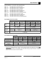
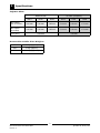
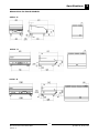
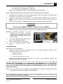
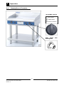
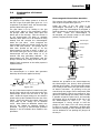
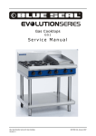
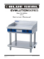
Gas Griddles
GP51
Service Manual
Blue Seal Evolution Series Gas Griddles
Revision 1/
© Moffat Ltd, January 2007
WARNING:
ALL INSTALLATION AND SERVICE REPAIR WORK MUST BE CARRIED OUT BY
QUALIFIED PERSONS ONLY.
IMPORTANT: MAKING ALTERATIONS MAY VOID WARRANTIES AND APPROVALS.
Blue Seal Evolution Series Gas Griddles
Revision 1/
© Moffat Ltd, January 2007
Contents
This manual is designed to take a more in depth look at the Blue Seal Gas Griddles for the purpose of
making the units more understandable to service people.
There are settings explained in this manual that should never require to be adjusted, but for completeness
and those special cases where these settings are required to change, this manual gives a full explanation
as to how, and what effects will result.
Section
Page Number
1.
Specifications ............................................................................................ 1
2.
Installation ................................................................................................ 7
3.
Operation ................................................................................................. 10
3.1
3.2
Description of Controls
Explanation of Control System
4.
Maintenance ............................................................................................ 12
5.
Trouble-shooting Guide ........................................................................... 15
5.1
5.2
6.
Trouble-shooting Chart
Fault Diagnosis
Service Procedures .................................................................................. 18
6.1
6.2
6.3
Access
Replacement
Adjustment / Calibration
7.
Accessories .............................................................................................. 23
8.
Exploded Parts Diagrams ........................................................................ 24
8.1
8.2
8.3
8.4
9.
G514 600mm Griddle
G516 900mm Griddle
G518 1200mm Griddle
Base Options
Service Contacts ...................................................................................... 33
Appendix A: Gas Type Conversion ................................................................. 35
Blue Seal Evolution Series Gas Griddles
Revision 1/
© Moffat Ltd, January 2007
Blue Seal Evolution Series Gas Griddles
Revision 1/
© Moffat Ltd, January 2007
Specifications
1
Model Numbers covered in this Specification
GP514 - B
GP514 - CB
GP514 - LS
Gas Griddle 600mm wide Bench Model.
Gas Griddle 600mm wide with Cabinet Base.
Gas Griddle 600mm wide on Leg Stand.
GP516
GP516
GP516
GP516
-
B
CB
LS
RB
Gas
Gas
Gas
Gas
Griddle
Griddle
Griddle
Griddle
900mm
900mm
900mm
900mm
GP518
GP518
GP518
GP518
-
B
CB
LS
RB
Gas
Gas
Gas
Gas
Griddle
Griddle
Griddle
Griddle
1200mm
1200mm
1200mm
1200mm
wide
wide
wide
wide
Bench Model.
with Cabinet Base.
on Leg Stand.
with Refrigerated Base.
wide Bench Model.
wide with Cabinet Base.
wide on Leg Stand.
wide with Refrigerated Base.
Gas Supply (Non UK models)
Natural Gas
GP514
Input
Rating
GP516
GP518
GP514
GP516
GP518
53 MJ/hr
80 MJ/hr
108 MJ/hr
53 MJ/hr
80 MJ/hr
108 MJ/hr
(50,234 BTU) (75,825 BTU) (102,364 BTU) (50,234 BTU) (75,825 BTU) (102,364 BTU)
Supply
Pressure
Operating
Pressure
LP Gas (Propane)
1.13 - 3.40 kPa
(4.5” - 13.5” w.c.)
0.85 kPa (*)
(3.4” w.c.)
2.75 - 3.40 kPa
(11” - 13.5” w.c.)
0.90 kPa (*)
(3.6”w.c.)
2.5 kPa (*)
(9.8” w.c.)
Gas
Connection
2.6 kPa (*)
(10.2” w.c.)
¾” BSP Male
Gas Supply (Non UK models)
Natural Gas (G20)
Heat Input (nett)
Gas Rate (nett)
GP514
GP516
GP518
GP514
GP516
GP518
13.3 kW
21 kW
28.5 kW
13.3 kW
21 kW
28.5 kW
1.03 kg/hr
1.63 kg/hr
2.21 kg/hr
3
1.41 m /hr
Supply Pressure
Burner Operating
Pressure
Gas Connection
*
Propane (G31)
3
3
2.22 m /hr
3.02 m /hr
20 mbar
8.5 mbar (*)
37 mbar
8.2 mbar (*)
3
26 mbar (*)
/4” BSP Male
The burner operating pressure is to be measured at the gas control valve outlet test point with one
griddle burner operating at ‘High’ setting. The operating pressure is ex-factory set, through the
appliance regulator and not to be adjusted, apart from when carrying out gas conversion, if required.
(Refer to the ‘Gas Conversion’ section for details).
1
Blue Seal Evolution Series Gas Griddles
Revision 1/
© Moffat Ltd, January 2007
1
Specifications
Injector Sizes
Natural Gas
LP Gas (Propane)
G514
G516
G518
G514
G516
G518
Main Injector
(Non-UK models)
3.60 mm
3.00 mm
2.85 mm
2.10 mm
1.80 mm
1.70 mm
Main Injector
(UK models)
3.40 mm
3.00 mm
2.85 mm
2.10 mm
1.80 mm
1.70 mm
Pilot Injector
0.41 mm
0.25 mm
Removable Griddle Plate Weights
G514
50 Kgs (approx.)
G516
75 Kgs (approx.)
G518
100 Kgs (approx.)
2
Blue Seal Evolution Series Gas Griddles
Revision 1/
© Moffat Ltd, January 2007
Specifications
1
Dimensions for Bench Models
GP514 - B
GP516 - B
GP518 - B
3
Blue Seal Evolution Series Gas Griddles
Revision 1/
© Moffat Ltd, January 2007
1
Specifications
Dimensions for Cabinet Base Models
GP514 - CB
GP516 - CB
GP518 - CB
4
Blue Seal Evolution Series Gas Griddles
Revision 1/
© Moffat Ltd, January 2007
Specifications
1
Dimensions for Leg Stand Models
GP514 - LS
GP516 - LS
GP518 - LS
5
Blue Seal Evolution Series Gas Griddles
Revision 1/
© Moffat Ltd, January 2007
1
Specifications
Dimensions for Refrigeration Base Models
GP516 - RB
GP518 - RB
6
Blue Seal Evolution Series Gas Griddles
Revision 1/
© Moffat Ltd, January 2007
Installation
2
Installation Requirements
NOTE:
• It is most important that this appliance is installed correctly and that operation is correct before use.
Installation shall comply with local gas, health and safety requirements.
• This appliance shall be installed with sufficient ventilation to prevent the occurrence of
unacceptable concentrations of health harmful substances in the room, the appliance is installed in.
Blue Seal Gas Griddles are designed to provide years of satisfactory service and correct installation is
essential to achieve the best performance, efficiency and trouble-free operation.
This appliance must be installed in accordance with National installation codes and in addition, in
accordance with relevant National / Local codes covering gas and fire safety.
Australia:
New Zealand:
United Kingdom:
Ireland:
- AS5601
- Gas Installations.
- NZS5261
- Gas Installation.
- Gas Safety (Installation & Use) Regulations 1998.
- BS6173
- Installation of Catering Appliances.
- BS5440
- 1 & 2 Installation Flueing & Ventilation.
- IS 820
- Non - Domestic Gas Installations.
Installations must be carried out by authorised persons only. Failure to install equipment to the
relevant codes and manufacturer’s specifications shown in this section will void the
warranty.
Components having adjustments protected (e.g. paint sealed) by the manufacturer are only
allowed to be adjusted by an authorised service agent. They are not to be adjusted by the
installation person.
Unpacking
• Remove all packaging and transit protection from the appliance including all protective plastic
coating from the exterior stainless steel panels.
• Check equipment and parts for damage.
•
•
•
Report any damage immediately to the carrier and
distributor.
Ensure that the 4 adjustable feet are fitted with the protruding centre screw.
Report any deficiencies to the distributor who supplied the appliance.
Check that the available gas supply is correct to that shown on the rating plate located behind the front
control panel and on the inner face of the right hand panel.
Location
1.
Installation must allow for a sufficient flow of fresh air for the combustion air supply.
Natural Gas (G20)
LPG / Propane (G31)
2.
3.
4.
5.
6.
Combustion Air Requirements:
GP514
GP516
21 m3/hr
14 m3/hr
15 m3/hr
22 m3/hr
GP518
28 m3/hr
29 m3/hr
Installation must include adequate ventilation means, to prevent dangerous build up of combustion products.
Any gas burning appliance requires adequate clearance and ventilation for optimum and
trouble-free operation. The minimum installation clearances shown below are to be adhered to.
Position the appliance in its approximate working position.
All air for burner combustion is supplied from underneath the unit. The legs must always be fitted and no
obstructions placed on the underside or around the base of the unit, as obstructions will cause incorrect
operation and/or failure of the appliance.
Components having adjustments protected (e.g. paint sealed) by manufacturer are only allowed to be
adjusted by an authorised service agent. They are not to be adjusted by the installation person.
NOTE: Do not obstruct or block the appliances flue.
system to the appliance flue outlet.
Never directly connect a ventilation
7
Blue Seal Evolution Series Gas Griddles
Revision 1/
© Moffat Ltd, January 2007
2
Installation
Clearances
NOTE: Only non-combustible materials can be used in close proximity to this appliance.
Left/Right Hand Side
Rear
Combustible Surface Non Combustible Surface
50 mm
0 mm
50 mm
0 mm
Assembly
NOTE:
• All Models are delivered completely assembled. No further assembly is required.
• This appliance is fitted with adjustable feet to enable the appliance to be positioned
securely and level. This should be carried out on completion of the gas connection. Refer
to the ‘Gas Connection’ section.
Optional Accessories (Refer to Replacement Parts List)
• Rear Roller Kit. For installation details, refer to the instructions supplied with each kit.
• Plinth Kit. For installation details, refer to the instructions supplied with each kit.
Gas Connection
NOTE: ALL GAS FITTING MUST ONLY BE CARRIED OUT BY AN AUTHORISED PERSON.
1.
2.
Blue Seal Gas Griddles do not require an electrical connection, as they function totally on the gas
supply only.
It is essential that the gas supply is correct for the appliance to be installed and that adequate
supply pressure and volume is available. The following checks should therefore be made before
installation:a. Gas Type the appliance has been supplied for is
shown on coloured stickers located above the gas
connection and next to the rating plate. Check that
this is correct for the gas supply the appliance is being installed for. The gas conversion procedure is
detailed in this manual.
b. Supply Pressure required for this appliance is
shown in the “Specifications” section of this manual.
Check the gas supply to ensure adequate supply
pressure exists.
c. Input Rate of this appliance is stated on the Rating
Plate, refer to the ‘Dimensions’ section for rating plate
locations for the different models. The input rate
should be checked against the available gas supply
line capacity. Particular note should be taken if
the appliance is being added to an existing
installation.
Rating Plate Location
for Leg Stand Models
Fig 1
NOTE: It is important that adequately sized piping runs directly to the connection joint on the
appliance with as few tees and elbows as possible to give maximum supply volume.
3.
Fit the gas regulator supplied, into the gas supply line as close to the appliance as possible.
NOTE: The gas pressure regulator provided with this appliance is convertible between Natural Gas
and LPG and is already converted ex-factory to the gas type labelled beside the gas
connection point. The regulator outlet pressure is fixed ex-factory and it is NOT to be
adjusted.
8
Blue Seal Evolution Series Gas Griddles
Revision 1/
© Moffat Ltd, January 2007
Installation
2
The regulator connections are 3/4" BSP female.
The connection to the appliance is 3/4" BSP male.
(Refer to the “Specifications” section for the gas supply location dimensions).
NOTE: A Manual Isolation Valve must be fitted to the individual appliance supply line.
4.
5.
6.
Correctly locate the appliance into its final operating position and using a spirit level, adjust the legs
so that the unit is level and at the correct height.
Connect the gas supply to the appliance. A suitable jointing compound which resists the
breakdown action of LPG must be used on every gas line connection, unless compression fittings are
used.
Check all gas connections for leakages using soapy water or other gas detecting equipment.
WARNING:
DO
7.
NOT USE A NAKED FLAME TO CHECK FOR GAS LEAKAGES .
Check that the gas operating pressure is as shown in the “Specifications” section.
NOTE: The operating pressure is to be
measured at the burner operating
pressure test point outlet and with one
griddle burner operating at the “High
Flame” setting.
8.
9.
10.
Turn off the mains gas supply and bleed the
gas out of the appliance gas lines.
Turn on the gas supply and the appliance.
Verify the operating pressure remains
correct.
Burner Operating Pressure
Test Point (Outlet)
Fig 2
Commissioning
Before leaving the new installation;
Check the following functions in accordance with the operating instructions specified in the
“Operation” section of the User manual.
•
Light the Pilot Burner.
•
Light the Main Burner.
•
Turning 'Off' the Main Burner / Pilot.
Ensure that the operator has been instructed in the areas of correct lighting, operation, and
shutdown procedure for the appliance.
The User manual must be kept by the owner for future reference and a record of the Date of
Purchase, Date of Installation and the Serial Number of the Appliance must be recorded and kept
with the manual. (These details can be found on the Rating Plate, refer to the ‘Dimensions’
section for the locations of the Rating Plate for different applications. Also refer to the ‘Gas
Connection’ section).
NOTE: If for some reason it is not possible to get the appliance to operate correctly, shut off the
gas supply and contact the supplier of this appliance.
For the Refrigeration Cabinet Installation refer to the Refrigeration Cabinet Installation and
Operation Manual supplied with the appliance.
9
Blue Seal Evolution Series Gas Griddles
Revision 1/
© Moffat Ltd, January 2007
3
Operation
3.1
Description of Controls
Gas Griddle Controls
OFF Position
PILOT Burner
Temperature Gradient
Piezo Igniter
Viewing Hole
with
Fig 3
10
Blue Seal Evolution Series Gas Griddles
Revision 1/
© Moffat Ltd, January 2007
Operation
3.2
3
Explanation of Control
System
Safety System
Electromagnetic Flame Failure Gas Valve
The purpose of the safety system is to shut off
the flow of gas if the pilot flame goes out. It is
comprised of the flame itself, the thermocouple,
and the flame failure gas valve.
The purpose of the safety valve is to shut off the
flow of gas if the pilot flame goes out.
Inside the body of the gas valve is an
electromagnet connected to a spring loaded
plunger. When the electromagnet is energized, it
holds the plunger in, allowing gas to flow through
the valve.
When the electromagnet is
de-energized, the plunger snaps to the closed
position, stopping the flow of gas.
The pilot flame is lit by holding in the gas
control knob, which in turn temporarily pushes
the plunger inside the safety valve open and
allows gas to flow through. Once the burner is
lit, the thermocouple will begin to generate
millivolts (after about 10 to 30 seconds of being
heated) and will energize the electromagnet
inside the gas valve.
Once energized the
electromagnet holds the plunger inside the gas
valve in the open position. The plunger has to
have been pushed all the way in for the
electromagnet to be able to hold it in place. If
the burner flame goes out for some reason, the
thermocouple will cool after about 10 to 30
seconds and stop generating millivolts. The
electromagnet will then de-energize, and the
plunger will snap shut, cutting off the flow of gas.
Thermocouple
Electromagnet
Plunger
Gas flow
Shaft
Knob
Detail of each component in the safety system is
explained below.
Gas flow
Plunger
Thermocouple
The thermocouple is a device that generates
electricity when heat is applied to the tip.
Insulator
Internal
Wire
Nut
Conductor
Figure 3.2b
Tip
Millivolts are provided to the electromagnet by
the thermocouple (not shown) which generates
millivolts when heated. The thermocouple screws
into a fitting at the back of the gas valve to make
an electric connection. By pressing in the gas
control knob, the plunger can be temporarily held
open while lighting. There's two reasons for this;
gas has to flow through the safety valve to make
it possible to light the pilot burner, and secondly
the plunger has to be pushed all the way in for
the electromagnet to hold it in.
I.e.; the
electromagnet is strong enough to hold the
plunger in once there, but is not strong enough
to pull it in by itself. Sometimes a problem with
the flame not staying lit after releasing the button
can be attributed to not pushing the plunger all
the way in.
Figure 3.2a
The tip of the thermocouple is located in the pilot
burner flame, and the nut at the other end of the
thermocouple screws into the back of the gas
valve. Inside the copper tubing is a wire which is
joined at the tip but insulated from the rest of the
tubing. These two parts (the copper tubing and
wire) make up the "wiring" for an electrical
circuit. When these two dissimilar metals, wire
and tip, are heated an electrical voltage is
produced. This type of thermocouple generates
between 7 and 30 millivolts when heated in the
pilot flame.
11
Blue Seal Evolution Series Gas Griddles
Revision 1/
© Moffat Ltd, January 2007
4
Cleaning / Maintenance
CAUTION:
Always turn off the gas supply before cleaning.
This unit is not water proof.
Do not use water jet spray to clean interior or exterior of this appliance.
Routine Maintenance
To achieve the best results cleaning must be regular and thorough and all controls and mechanical
parts checked and adjusted periodically by a competent serviceman. If any small faults occur, have
them attended to promptly. Don't wait until they cause a complete breakdown. It is recommended
that the appliance is serviced every 6 months.
Clean the griddle regularly. A clean appliance looks better, will last longer and will perform better.
Carbonised grease on the surface or on the griddle plate will hinder the transfer of heat from the
cooking surface to the food. This will result in loss of cooking efficiency.
NOTE: Each griddle is supplied with a scraper tool and a pack of blades for cleaning the griddle
surface. Griddles with both ribbed and flat surfaces are supplied with two scraper tools and
two packs of blades for use with both flat and ribbed surfaces. These are for use with both
chromed and steel surfaced griddles. NEVER use the ribbed scraper blade on the flat
chrome surfaced griddle plate.
WARNING
THE BLADES FITTED TO THE
SCRAPER TOOL ARE EXTREMELY SHARP AND ARE TO BE USED WITH CARE.
DO NOT use water on the griddle plate while this item is still hot as warping and
cracking may occur. Allow the griddle plate to cool down before cleaning.
NOTE:
• DO NOT use abrasive detergents, strong solvents or caustic detergents as they could corrode or damage the range.
• In order to prevent the forming of rust on the griddle plate (Steel Plate), ensure that any
detergent or cleaning material has been completely removed after each cleaning. The appliance should be switched on briefly to ensure the griddle plate becomes dry. Oil or
grease should be spread over the griddle surface in order to form a thin protective greasy
film.
To keep your griddle clean and operating at peak efficiency, follow the procedures shown below:After Each Use
1.
Clean the griddle with the supplied scraper tools to remove any food debris.
C AUTI ON
Always ensure that an even pressure is applied over the whole surface of the
scraper tool when using on the flat chromed surface of the griddle, to prevent
scoring of the surface.
NEVER bang the sharp edge of the scraper tool on the flat chromed surface of
the griddle as this will damage the chrome finish and invalidate the warranty.
2.
Always ensure that the scraper tool blades are changed regularly to ensure that the scraper tool
works efficiently and prevents damage to the griddle plate surface.
12
Blue Seal Evolution Series Gas Griddles
Revision 1/
© Moffat Ltd, January 2007
Cleaning / Maintenance
4
Daily Cleaning
1.
2.
3.
4.
The grease drawer should be checked and emptied frequently to prevent overflow and spillage.
Remove the grease drawer while still warm so that the grease is in a liquid state. Empty any grease
from the drawer and wash thoroughly in the same manner as any cooking utensil.
Thoroughly clean the splash back, the interior and exterior surfaces of the range with hot water, a
detergent solution and a soft scrubbing brush.
Brush the griddle surface with a soft bristled brush. Any carbon deposits should be removed using
the supplied scraper tool followed by wiping with a cloth to prevent accumulation of food
deposits.
Dry the griddle thoroughly with a dry cloth and polish with a soft dry cloth.
NOTE: Chrome Griddle Plate; DO NOT use abrasive detergents, strong solvents or caustic detergents as they could corrode or damage the chrome plate.
Weekly Cleaning
NOTE:
• If the griddle usage is very high, we recommend that the weekly cleaning procedure is
carried out on a more frequent basis.
• Ensure that protective gloves are worn during the cleaning process.
• DO NOT use harsh abrasive detergents, strong solvents or caustic detergents as they will
damage the range and burners.
• DO NOT use water on the griddle plates while they are still hot as warping may occur.
Allow these items castings to cool and remove for cleaning.
Griddle - Steel Plate
NOTE: In order to prevent the forming of rust on the griddle plate, ensure that all detergent and
cleaning material has been entirely removed after each cleaning process. The appliance
should be switched on briefly to ensure the griddle plate becomes dry. Oil or grease should
be spread over the griddle surface in order to form a thin protective greasy film.
a. Remove and clean the grease collection drawer frequently to prevent over spills.
b. Clean the griddle surface thoroughly with the supplied scraper tool or a wire brush. If necessary
use a griddle stone or a scotch bright pad on the griddle surface for the removal of stubborn or
accumulated carbon deposits..
c. Occasionally bleach the griddle plate with vinegar when the plate is cold.
d. Clean with hot water, a mild detergent solution and a scrubbing brush. Dry all components thoroughly with a dry cloth.
e. The griddle should be switched on briefly to ensure that the griddle plate becomes dry. A thin
smear of cooking oil should be spread over the griddle in order to form a protective film.
13
Blue Seal Evolution Series Gas Griddles
Revision 1/
© Moffat Ltd, January 2007
4
Cleaning / Maintenance
Griddle - Chrome Plate
C AUTI ON
Always ensure that an even pressure is applied over the whole surface of the
scraper tool when using on the flat chromed surface of the griddle, to prevent
scoring of the surface.
NEVER bang the sharp edge of the scraper tool on the flat chromed surface of
the griddle as this will damage the chrome finish and invalidate the warranty.
NOTE: In order to maintain the finish on the chrome griddle plate, ensure that all detergent and
cleaning material has been entirely removed after each cleaning process. The appliance
should be switched on briefly to ensure the griddle plate becomes dry.
a. Remove and clean the grease collection drawer frequently to prevent over spills.
b. Clean the griddle surface thoroughly with the supplied scraper tool.
c. Allow the plate to cool, then clean the plate with a scrubbing brush, a mild non-abrasive
detergent and water.
d. Occasionally bleach the plate with vinegar when cold.
e. Dry the griddle thoroughly with a dry cloth and polish with a soft dry cloth.
f. The griddle should be switched on briefly to ensure that the griddle plate becomes dry.
Griddle Cooking Area
a. Clean the griddle cooking area with a soft cloth and a mild detergent and hot water solution.
b. Baked on deposits or discolouration may require a good quality stainless steel cleaner or stainless
steel wool. Always apply cleaner when the appliance is cold and rub in the direction of the grain.
c. Remove the grease drawer and clean with a mild anti bacterial detergent and hot water solution
using a soft bristled brush. Dry the grease drawer thoroughly with a dry cloth.
Stainless Steel Surfaces
a. Clean the exterior surfaces of the griddle with hot water, a mild detergent solution and a soft
scrubbing brush. Note that the gas control knobs are a push fit onto the gas control valve
spindles and can be removed to allow cleaning of the front control panel.
b. Baked on deposits or discolouration may require a good quality stainless steel cleaner or stainless
steel wool. Always apply cleaner when the appliance is cold and rub in the direction of the grain.
c. To remove any discolouration, use an approved stainless steel cleaner or stainless steel wool.
Always rub in the direction of the grain.
d. Remove the grease tray and clean with a mild anti bacterial detergent and hot water solution
using a soft bristled brush.
e. Dry the grease tray thoroughly with a dry cloth.
f. Dry all components thoroughly with a dry cloth and polish with a soft dry cloth.
For the Refrigeration Cabinet Cleaning and Maintenance refer to the Refrigeration Cabinet
Installation and Operation Manual supplied with the appliance.
14
Blue Seal Evolution Series Gas Griddles
Revision 1/
© Moffat Ltd, January 2007
Trouble-shooting
WARNING:
5.1
5
ALL INSTALLATION AND SERVICE REPAIR WORK MUST BE CARRIED OUT BY
QUALIFIED PERSONS ONLY.
Trouble Shooting Chart
Fault
Pilot won’t light
Piezo ignitor not sparking.
Pilot flame small / lazy / yellow.
Pilot goes out when knob
released.
Possible cause
Remedy
Gas control knob not being held
in.
Hold in button while lighting pilot.
No gas supply.
Ensure gas is connected and on
(bottles not empty).
Gas pressure too low.
Check gas supply pressure.
(Refer specifications section)
Blocked pilot injector.
Clean or replace pilot injector.
(Refer service section 6.2.8)
Gas control faulty.
Replace.
(Refer service section 6.2.12)
Short in high tension lead.
(Refer fault diagnosis 5.2.2)
Replace lead.
(Refer service section 6.2.11)
Piezo faulty.
(Refer fault diagnosis 5.2.2)
Replace piezo.
(Refer service section 6.2.14)
Gas pressure too low.
Check gas supply pressure.
(Refer specifications section)
Blocked / incorrect size pilot
injector.
Clean or replace pilot injector.
(Refer service section 6.2.8)
Releasing knob before the
thermocouple is heated.
Hold control in for longer (10 s),
see if pilot will stay lit.
Pilot flame too small.
Correct fault.
(Refer fault:Pilot Flame Small)
Main burners will not light.
Thermocouple faulty.
(Refer fault diagnosis 5.2.1)
Replace thermocouple.
(Refer service section 6.2.9)
Gas magnet faulty.
(Refer fault diagnosis 5.2.1)
Replace gas magnet.
(Refer service section 6.2.13)
Wrong size or blocked injectors.
Replace / clean injectors.
(Refer service section 6.2.6)
Obstruction in burner.
Clean burner.
Incorrect supply pressure.
Check supply pressure.
Faulty gas control.
Replace gas control.
(Refer service section 6.2.12)
15
Blue Seal Evolution Series Gas Griddles
Revision 1/
© Moffat Ltd, January 2007
5
Trouble-shooting
Fault
Main burner flame
incorrect colour (yellow / wavy).
Pilot goes out when main burner
comes on.
Possible cause
Remedy
Aeration setting incorrect.
Adjust aeration.
(Refer service section 6.4.4)
Incorrect gas pressure.
Check supply pressure.
Incorrect injector size.
Check injector correct size.
Obstruction in burner.
Inspect burner for obstruction.
Incorrect gas pressure.
Check supply / adjust pressure.
(Refer specifications section)
Faulty gas control.
Replace gas control.
(Refer service section 6.2.12)
16
Blue Seal Evolution Series Gas Griddles
Revision 1/
© Moffat Ltd, January 2007
Trouble-shooting
5.2.2
5.2
Fault diagnosis
5.2.1
Pilot goes out when pilot
knob is released
5
Piezo ignitor not sparking
Short in high tension lead
If repeated sparking of the piezo shows
intermittent sparking at the electrode, then the
lead should be traced to find area of short. This
can normally be visually seen as the spark arcs.
If the lead is shorting the best solution is to
replace it, as the electrical insulation strength of
the lead may have deteriorated.
Pilot flame too small
If pilot can be lit but the flame is too small to impinge on the thermocouple, then check the gas
pressure. If ok, remove pilot injector from pilot
burner and check for blockages and/or correct
size.
If the spark arc can be seen at the electrode
insulator at the pilot burner instead of at the
electrode tip, then the insulator probably has a
fracture and should be replaced.
Thermocouple faulty
Inspect thermocouple for build-up of carbon or
food deposits on the tip. Clean off any deposits,
taking care not to scratch off the aluminium
coating on the thermocouple.
Piezo ignitor faulty
If no spark at all can be generated, remove piezo
ignitor and hold close to the hob body, depress
piezo ignitor and if a spark cannot be generated
to hob body the piezo ignitor is faulty and should
be replaced.
Check that the thermocouple tip is in the flame
zone of the pilot burner. When the burner is lit,
the flame should impinge on the top 5mm of the
thermocouple tip.
NOTE: The thermocouple should not touch the
burner.
Check
thermocouple
connection
to
gas
control is firm (loose connections will cause resistance in millivolt circuit and result in pilot outage).
If connection is OK, then disconnect the
thermocouple from the gas control, light the pilot,
and whilst holding the control knob in, measure
voltage between the thermocouple internal wire
(refer figure 5.2.1) and earth (e.g. the body of
the gas control). This should read approximately
30mV. If this reading is less than 10mV then the
thermocouple is faulty—replace.
Tip
Internal Wire
Figure 5.2.1
Gas magnet faulty
If thermocouple milli-voltage is above 10mV, and
the pilot still will not hold, then the gas magnet is
faulty - replace.
NOTE: Oven valves will require replacement if
the gas magnet is faulty.
17
Blue Seal Evolution Series Gas Griddles
Revision 1/
© Moffat Ltd, January 2007
6
Service Procedures
Section
Page no.
6.1 Access .................................................................................................... 18
6.1.1
Control Panel........................................................................................................... 18
6.2 Replacement ........................................................................................... 18
6.2.1
6.2.2
6.2.3
6.2.4
6.2.5
6.2.6
6.2.7
6.2.8
Griddle Burner ......................................................................................................... 18
Griddle Burner Injector ............................................................................................. 19
Pilot Burner ............................................................................................................. 19
Pilot Burner Injector ................................................................................................. 20
Thermocouple ......................................................................................................... 20
Spark Electrode ....................................................................................................... 20
Piezo Ignitor ........................................................................................................... 20
Gas Control Valve .................................................................................................... 20
6.3 Adjustment / Calibration ....................................................................... 21
6.3.1
Thermostat Calibration ............................................................................................. 21
WARNING:
ALL INSTALLATION AND SERVICE REPAIR WORK MUST BE CARRIED OUT BY
QUALIFIED PERSONS ONLY.
ENSURE GAS SUPPLY IS SWITCHED OFF BEFORE SERVICING
ALWAYS CHECK / TEST FOR GAS LEAKS AFTER SERVICE REPAIRS ON THE GAS
SYSTEM
18
Blue Seal Evolution Series Gas Griddles
Revision 1/
© Moffat Ltd, January 2007
Service Procedures
6.1
Access
6.2
6.1.1
Control panel
6.2.1 Griddle Burner
securing
Replacement
1) Remove the griddle plate control panel (refer
section 6.1.1).
1) Remove all gas control knobs by pulling away
from the control panel.
2) Remove the two screws
control panel to the hob.
6
2) Using the jacking screw provided, lift the
griddle plate as high as possible.
the
3) Disconnect H.T leads from rear of piezo
ignitors on control panel.
4) Remove the control panel.
Jacking screw
Gas control knobs
Figure 6.2.1a
3) Withdraw all thermostat capillaries and phials
from their pockets underneath the plate.
Two screws
Figure 6.1.1
Figure 6.2.1b
4) Lift the plate off the unit. A second person
may be required.
5) Undo the two screws at the rear of the
burner.
6) Undo the two screws securing the burner
venturi cover. Remove the venturi cover from
the burner.
19
Blue Seal Evolution Series Gas Griddles
Revision 1/
© Moffat Ltd, January 2007
6
Service Procedures
6.2.2 Griddle Burner Injector
1) Remove the griddle plate control panel (refer
section 6.1.1).
2) Unscrew the griddle burner injector from its
mounting bracket.
3) Clean or replace as necessary and reassemble
in reverse order.
Injector
Figure 6.2.1c
Figure 6.2.2
7) The burner can now be withdrawn from the
unit. Replace and reassemble in reverse order.
6.2.3 Pilot Burner
Note: When reassembling, it is important that
the thermostat phials are correctly located.
These should be pushed fully into the block
on the underside of the griddle plate. A small
hole in the burner box panel indicated the
approximate position of the thermostat phial
block.
1) Remove the griddle plate control panel (refer
section 6.1.1).
2) Disconnect the piezo electrode, thermocouple,
and pilot supply tube from the pilot burner
assembly.
3) Undo the two screws securing the pilot burner
to the burner box.
4) Withdraw the pilot burner and replace.
Reassemble in reverse order.
Figure 6.2.1d
Figure 6.2.3
20
Blue Seal Evolution Series Gas Griddles
Revision 1/
© Moffat Ltd, January 2007
Service Procedures
6
6.2.4 Pilot Burner Injector
6.2.7 Piezo Ignitor
1) Remove the pilot burner (refer 6.2.3).
1) Remove the griddle plate control panel (refer
section 6.1.1).
2) Withdraw the pilot burner injector from the
pilot burner.
2) Remove the HT lead form the rear of the
piezo ignitor by pulling firmly away.
3) Clean or replace as necessary.
3) Unscrew the nut securing the piezo ignitor to
the control panel.
4) Reassemble in reverse order.
4) Replace ignitor and reassemble.
6.2.5 Thermocouple
1) Remove the griddle plate control panel (refer
section 6.1.1).
6.2.8 Gas Control
2) Disconnect the thermocouple from the pilot
burner assembly.
1) Remove the griddle plate control panel (refer
section 6.1.1).
3) Undo the thermocouple from the rear of the
gas control valve.
2) Using the jacking screw provided, lift the
griddle plate as high as possible.
4) Replace thermocouple and reassemble.
NOTE: When screwing thermocouple back into
gas control, once threaded up tighten up
another ¼ turn only. Do not over-tighten.
Jacking screw
Figure 6.2.8a
3) Withdraw the thermostat capillary and phial
from it’s pocket underneath the plate.
Figure 6.2.5
6.2.6 Spark Electrode
1) Remove the griddle plate control panel (refer
section 6.1.1).
2) Undo the spark electrode from the pilot
burner assembly.
3) Replace electrode and reassemble.
Figure 6.2.8b
21
Blue Seal Evolution Series Gas Griddles
Revision 1/
© Moffat Ltd, January 2007
6
Service Procedures
4) Disconnect the pilot supply tube and thermocouple from the rear of the gas control valve.
6.3
Adjustment/ calibration
6.3.1
Thermostat Calibration
Note: It is recommended that the faulty gas
valve is replaced, rather than recalibrated.
As the thermostat control has special
fasteners, a Torx T20 security tip or
screwdriver is required. These are readily
available from a tool retailer.
1) Place
an
accurate
thermometer
thermocouple in the centre of the oven.
or
2) Light burner and set the thermostat knob to
200°C.
3) Wait for the oven temperature to stabilise
(approximately 20 minutes). Oven centre
temperature should be 200°C ± 10°C.
Figure 6.2.8c
4) Remove the shaft extension (A) by loosening
off grub screw with the appropriate sized
allan key.
5) Disconnect the gas supply pipe, and main
burner supply pipe from the gas control valve.
6) Undo the mounting screws securing the gas
control valve to the mounting bracket.
5) With the control knob (C) in the off position
and while holding it in, undo the Torx head
screw (B).
7) Replace gas valve and reassemble. Ensure
that the gas valve is set up correctly (correct
low fire screw fitted etc).
6) Pull the control knob (C) straight off taking
care not to rotate it at all while extracting.
Ensure the spring (D) is not lost.
Note: When reassembling, it is important that
the thermostat phials are correctly located.
These should be pushed fully into the block
on the underside of the griddle plate. A small
hole in the burner box panel indicated the
approximate position of the thermostat phial
block.
7) Put a mark on the gear (E) for future
reference to rotation of gear.
8) Carefully rotate the gear (E) for adjustment.
One tooth rotation equals a temperature
change of 5ºC.
Anticlockwise to decrease temperature.
9) Replace the knob, ensuring spring is in
position and taking care not to rotate the
knob while inserting, hold fully in.
E
D
C
B
A
Figure 6.2.8d
Figure 6.3.1
10) Replace Torx head screw and release knob.
11) Test oven temperature, and re-adjust if
required.
12) Push snap cap back into position on knob.
22
Blue Seal Evolution Series Gas Griddles
Revision 1/
© Moffat Ltd, January 2007
Accessories
7
Accessories
228566
228567
228568
228921
228795
228799
228803
228801
228805
Griddle Scraper Tool.
Smooth Plate Scraper Blades
Ribbed Plate Scraper Blade
Rear Roller Kit.
600 mm Plinth Kit
900 mm Plinth Kit
1200 mm Plinth Kit
Refrigeration Base - 900 mm Plinth Kit
Refrigeration Base - 1200 mm Plinth Kit
(Pack of 5 blades).
(Individual Blade).
(LS and CB
(LS and CB
(LS and CB
(RB Models
(RB Models
Models only).
Models only).
Models only).
only).
only).
23
Blue Seal Evolution Series Gas Griddles
Revision 1/
© Moffat Ltd, January 2007
8
Exploded Parts Diagrams
8.1
GP514 600mm Griddle
8.1.1
GP514 Main Assembly
Item
1
2
3
4
5
6
7
8
9
10
Part No
228653
PGH620
PGH620R3
PGH620R6
PGH620C
PGH620R3C
227656
227550
227584
228400
228010
227508
227380
228173
227960
Description
SPLASHBACK BLUE SEAL
GRIDDLE G 600x20
GRIDDLE G 600x20 RIB300RH
GRIDDLE G 600x20 RIB600
GRIDDLE G 600x20 CHROMED
GRIDDLE G 600x20 RIB300RH CHROMED
GRIDDLE G 600x20 RIB600 CHROMED
CONTROL PANEL
FRONT TRIM BLUE SEAL
GREASE DRAWER WA
PIEZO HOUSING
PIEZO - SIT
KNOB BSEAL 8MM 90-300°C
SPLASHBACK ENDS
BLUE SEAL BADGE
24
Blue Seal Evolution Series Gas Griddles
Revision 1/
© Moffat Ltd, January 2007
Exploded Parts Diagrams
8.1.2
Item
11
12
13
14
15
16
17
18
19
20
21
22
23
24
25
8
GP514 Gas Assembly
Part No
227444
228625
228522
032360
032340
032210
228393
230132
024156
019624
019464K
228047
229407
018097
230319
019593
019594
019218
Description
GRIDDLE BURNER
SUPPLY PIPE
EUROSIT MANIFOLD PIPE LH
INJECTOR 3.60mm (NAT GAS)
INJECTOR 3.40mm (UK NAT GAS)
INJECTOR 2.10mm (LPG/PROPANE)
EUROSIT KNOB ADAPTOR
EUROSIT GAS THERMOSTAT 80-320°
FLEXTUBE DORMONT T6X12
ELECTRODE
PILOT BURNER KIT
HT LEAD 250mm
GRIDDLE OVERTEMP 365°
PILOT SIT 100 SERIES OLIVE NUT 16mm
FLEXTUBE 12"x1/4 OD ST/ST
PILOT SPUD 0.41mm (NAT GAS)
PILOT SPUD 0.25mm (LPG / PROPANE)
THERMOCOUPLE 450MM
25
Blue Seal Evolution Series Gas Griddles
Revision 1/
© Moffat Ltd, January 2007
8
Exploded Parts Diagrams
8.2
GP516 900mm Griddle
8.2.1
GP516 Main Assembly
Item
1
2
3
4
5
6
7
8
9
10
Part No
228656
PGH920
PGH920R3
PGH920R5
PGH920R9
PGH920C
PGH920R3C
PGH920R9C
227549
227580
227380
227508
228010
228400
228173
227960
Description
SPLASHBACK BLUE SEAL
GRIDDLE G 900X20
GRIDDLE G 900x20 RIB300RH
GRIDDLE G 900x20 RIB450RH
GRIDDLE G 900x20 RIB900
GRIDDLE G 900X20 CHROMED
GRIDDLE G 900x20 RIB300RH CHROMED
GRIDDLE G 900x20 RIB900 CHROMED
CONTROL PANEL
FRONT TRIM BLUE SEAL
KNOB BSEAL 8MM 90-300°C
PIEZO - SIT
PIEZO HOUSING
GREASE DRAWER WA
SPLASHBACK ENDS
BLUE SEAL BADGE
26
Blue Seal Evolution Series Gas Griddles
Revision 1/
© Moffat Ltd, January 2007
Exploded Parts Diagrams
8.2.2
Item
11
12
13
14
15
16
17
18
19
20
21
22
23
24
25
26
27
8
GP516 Gas Assembly
Part No
227443
228526
228626
228522
032300
032180
228393
230132
228541
227443
019624
019464K
228047
229407
018097
230319
019593
019594
019218
Description
GRIDDLE BURNER RH
EUROSIT MANIFOLD PIPE RH
MANIFOLD ASSEMBLY WA
EUROSIT MANIFOLD PIPE LH
INJECTOR 3.00 mm (NAT GAS)
INJECTOR 1.80 mm (LPG / PROPANE)
EUROSIT KNOB ADAPTOR
EUROSIT GAS THERMOSTAT 80-320°
BURNER SUPPLY TUBE LH
GRIDDLE BURNER LH
ELECTRODE
PILOT BURNER KIT
HT LEAD 250mm
GRID OVERTEMP 365°
PILOT SIT 100 SERIES OLIVE NUT 16mm
FLEXTUBE 12"x1/4 OD ST/ST
PILOT SPUD 0.41mm (NAT GAS)
PILOT SPUD 0.25mm (LPG / PROPANE)
THERMOCOUPLE 450MM
27
Blue Seal Evolution Series Gas Griddles
Revision 1/
© Moffat Ltd, January 2007
8
Exploded Parts Diagrams
8.3
GP518 1200mm Griddle
8.3.1
GP518 Main Assembly
Item Part No
1 228925
2 PGH1220
PGH1220R4
PGH1220R6
PGH1220R12
PGH1220C
PGH1220R4C
3 227548
4 227581
5 228400
6 227508
7 228010
8 227381
9 228173
10 227960
Description
SPLASHBACK 1200 BLUE SEAL WA
GRIDDLE G 1200X20
GRIDDLE G 1200x20 RIB400RH
GRIDDLE G 1200x20 RIB600RH
GRIDDLE G 1200x20 RIB1200
GRIDDLE G 1200X20 CHROMED
GRIDDLE G 1200x20 RIB400RH CHROMED
CONTROL PANEL
FRONT TRIM BLUE SEAL
GREASE DRAWER WA
PIEZO - SIT
PIEZO HOUSING
KNOB BSEAL 8MM 100-290°C
SPLASHBACK ENDS
BLUE SEAL BADGE
28
Blue Seal Evolution Series Gas Griddles
Revision 1/
© Moffat Ltd, January 2007
Exploded Parts Diagrams
8.3.2
Item
11
12
13
14
15
16
17
18
19
20
21
22
23
24
25
26
27
28
8
GP518 Gas Assembly
Part No
227443
228526
228626
228551
228549
032285
032170
228393
230132
024156
227443
019624
019464K
228047
229407
018097
230319
019593
019594
019216
Description
GRIDDLE BURNER RH
EUROSIT MANIFOLD PIPE RH
MANIFOLD ASSEMBLY WA
CONTROL SUPPLY BUNDY SHORT LH
CONTROL SUPPLY BUNDY LONG LH
INJECTOR 2.85 mm (NAT GAS)
INJECTOR 1.70 mm (LPG / PROPANE)
EUROSIT KNOB ADAPTOR
EUROSIT GAS THERMOSTAT 80-320°
FLEXTUBE DORMONT T6X12
GRIDDLE BURNER LH
ELECTRODE
PILOT BURNER KIT
HT LEAD 250mm
GRID OVERTEMP 365°
PILOT SIT 100 SERIES OLIVE NUT 16mm
FLEXTUBE 12"x1/4 OD ST/ST
PILOT SPUD 0.41mm (NAT GAS)
PILOT SPUD 0.25mm (LPG / PROPANE)
THERMOCOUPLE 450MM
29
Blue Seal Evolution Series Gas Griddles
Revision 1/
© Moffat Ltd, January 2007
8
Exploded Parts Diagrams
8.4
GP51 Base Options
8.4.1
Bench Mount Base
ITEM PART NO
1 230354
2 227123
227120
227125
3 227855
4 227852
5 230355
6 228313
227121
228314
DESCRIPTION
SIDE COVER RH
TOP TRIM 600MM WIDE
TOP TRIM 900MM WIDE
TOP TRIM 1200MM WIDE
LEG 80MM X Ø63.5
LEG PLATE
SIDE COVER LH
HOB BACK PANEL SUPPORT 600MM WIDE
HOB BACK PANEL SUPPORT 900MM WIDE
HOB BACK PANEL SUPPORT 1200MM WIDE
30
Blue Seal Evolution Series Gas Griddles
Revision 1/
© Moffat Ltd, January 2007
Exploded Parts Diagrams
8.4.2
ITEM
1
2
3
4
5
6
7
8
9
10
11
12
8
Cabinet Base
PART NO
227048
228321
227075
227901
227409
227790
227789
227791
227788
227787
227786
227850
227852
227049
229674
229671
227040
227104
227117
228935
DESCRIPTION
SIDE PANEL RH
SIDE RACK WA
SILL 600MM WA
SILL 900MM WA
SILL 1200MM WA
FILLER 600MM
FILLER 900MM
FILLER1200MM
SIDE SUPPORT 600MM
CENTRE SUPPORT 900MM
CENTER SUPPORT 1200MM
LEG 150MM X Ø63.5
LEG PLATE
SIDE PANEL LH
REAR ROLLER ASSEMBLY
LEG RING PLATE THREADED
BACK PANEL 600MM WIDE
BACK PANEL 900MM WIDE
BACK PANEL 1200MM WIDE
GAS HOUSING
31
Blue Seal Evolution Series Gas Griddles
Revision 1/
© Moffat Ltd, January 2007
8
Exploded Parts Diagrams
8.4.3
Leg Base
ITEM PART NO
1 230354
2 227123
227120
227125
3 227853
4 227408
227407
227409
5 227075
227901
227902
6 227851
7 229674
8 748010
9 229673
10 230355
11 228313
228312
228314
DESCRIPTION
SIDE COVER RH
TOP TRIM 600MM
TOP TRIM 900MM
TOP TRIM 1200MM
LEG EXTENSION 530 X Ø63.5
BASE TRAY 600MM
BASE TRAY 900MM
BASE TRAY 1200MM
SILL 600MM WA
SILL 900MM WA
SILL 1200MM WA
LEG 150MM X Ø63.5 EXTD THREAD
REAR ROLLER ASSEMBLY
SCREW 5/8"X1 HEX SET ZP
LEG RING PLATE PLAIN
SIDE COVER LH
HOB BACK PANEL SUPPORT 600MM
HOB BACK PANEL SUPPORT 900MM
HOB BACK PANEL SUPPORT 1200MM
32
Blue Seal Evolution Series Gas Griddles
Revision 1/
© Moffat Ltd, January 2007
Service Contacts
10
Australia
VICTORIA - MOFFAT PTY
HEAD OFFICE AND MAIN WAREHOUSE
740 Springvale Road
Mulgrave VIC 3170
Spare Parts Department
Tel (03) 9518 3888
Fax (03) 9518 3838
Free Call 1800 337 963
Fax (03) 9518 3895
NEW SOUTH WALES - MOFFAT PTY
Unit 3/142 James Ruse Drive
Rosehill NSW 2142
Spare Parts
Tel (02) 8833 4111
Free Call 1800 337 963
Fax (03) 9518 3895
QUEENSLAND - MOFFAT PTY
30 Prosperity Place
Geebung QLD 4034
Spare Parts
Tel (07) 3630 8600
Free Call 1800 337 963
Fax (03) 9518 3895
WESTERN AUSTRALIA - MOFFAT PTY
67 Howe St
Osbourne Park, WA 6017
Spare Parts
Tel (08) 9202 6820
Fax (08) 9202 6836
Free Call 1800 337 963
Fax (03) 9518 3895
NATIONAL COVERAGE FOR 24 HOUR SERVICE OR MAINTENANCE DIAL
FREE CALL 1800 622 216 (AUSTRALIA ONLY)
Canada
SERVE CANADA
22 Ashwarren Rd
Downview
Ontario M3J1Z5
Tel 416-631-0601
Fax 416-631-0315
New Zealand
CHRISTCHURCH - MOFFAT LTD
16 Osborne St
PO Box 10-001
Christchurch
Spare Parts
Tel (03) 389 1007
Fax (03) 389 1276
Free Call 0800 MOFFAT
(0800 66 33 28)
Fax (03) 381 3616
AUCKLAND - MOFFAT LTD
4 Waipuna Road
Mt Wellington
Auckland
Spare Parts
Tel (09) 574 3150
Fax (09) 574 3159
Free Call 0800 MOFFAT
(0800 66 33 28)
33
Blue Seal Evolution Series Gas Griddles
Revision 1/
© Moffat Ltd, January 2007
10
Service Contacts
United Kingdom
BLUESEAL LTD
67 Gravelly Industrial Park
Erdington
Birmingham B24 8TQ
England
Tel 0121 327 5575
Fax 0121 327 9711
United States of America
MOFFAT INC.
3765 Champion Blvd
Winston-Salem
NC27115
Tel 1800 551 8795
Fax 336 661 9546
NATIONAL COVERAGE FOR SERVICE OR MAINTENANCE DIAL
FREE CALL 1800 551 8795 (USA ONLY)
34
Blue Seal Evolution Series Gas Griddles
Revision 1/
© Moffat Ltd, January 2007
Appendix A: Gas Type Conversion
A
Conversion Procedure
C AUTIO N :
Ensure that the appliance is isolated from the gas supply before commencing
servicing.
NOTE:
• These conversions should only be carried out by qualified persons. All connections must be
checked for leaks before re-commissioning the appliance.
• Adjustment of components that have adjustments/settings sealed (e.g. paint sealed) can only be
adjusted in accordance with the following instructions and shell be re-sealed before recommissioning this appliance.
• For all relevant gas specifications refer to the ‘Gas Specifications’ table at the end of this section.
Main Burners
1.
2.
3.
4.
5.
6.
7.
Turn off the gas supply at the mains supply.
Turn off the power supply at the mains electrical supply.
Remove the gas control knobs from the front control panel.
The control knobs are a push fit onto the shaft of the gas
control valves.
Remove the front control panel by slackening the 2 screws
on the underside of the control panel and remove the panel
from the front of the appliance.
Take care to
disconnect the electrical connection lead from the rear of
the piezo igniter fitted to the control panel.
Unscrew and remove the injector (13 mm or ½” A/F) from
the main burner end clamp.
Determine the correct injector size for the corresponding
gas from the rating plate affixed behind the front control
panel and on the inner face of the right hand panel.
Replace with the correct size injectors. Refer to ‘Gas
Specifications Table’ for injector sizes.
Main Injector
Fig A1
Piezo
Igniter
Pilot Injector Gas
Supply Pipe
Pilot Burners
1.
2.
3.
4.
5.
6.
7.
To remove the pilot burner injector, disconnect the lead to
the piezo igniter and unscrew the piezo igniter from the
mounting bracket (this is precautionary to prevent damage
to the igniter).
Slacken the gas supply tube at the gas control unit end of
the supply tube to allow the tube to be moved easily
without bending.
Disconnect the gas supply tube from the base of the pilot
burner and withdraw the pilot injector from inside the pilot
burner.
Determine the correct injector size for the corresponding gas
from the rating plate affixed to the bulkhead by the manifold
test point.
Re-connect the supply tube to the base of the pilot burner
and tighten the gas supply tube at the gas control unit end.
Refit the piezo igniter to the mounting bracket.
Reconnect the electrical connection to the piezo igniter. This
is a push fit connection.
Thermocouple
Fig A2
Thermocouple
Piezo Igniter
Pilot Injector
Viewed from Inside the Burner Box
Fig A3
35
Blue Seal Evolution Series Gas Griddles
Revision 1/
© Moffat Ltd, January 2007
A
8.
9.
Appendix A: Gas Type Conversion
Refit the front control panel and tighten the 2 screws on the underside to secure the panel in place.
Refit the control knobs to the front control panel. The control knobs are a push fit onto the shafts of
the gas control valves.
Low Fire Adjustment - (Gas Griddle)
To change the gas griddle thermostat ‘Low Fire’ adjustment, the low fire screw on the gas control valve
should be screwed fully in, then unscrewed by 1 full turn as shown in the “Gas Specifications” table at the
end of this section.
1.
Remove the griddle gas control knob from the
front control panel. The knob is a push fit
Low Fire
Adjustment Screw
onto the shaft of the gas control valve.
2.
Remove the gas griddle control panel from the
front of the gas griddle by removing the 2
securing screws in the lower corners of the
panel.
3.
Screw the ‘Low Fire’ screw fully ‘IN’ and then
unscrew by 1 Full Turn of the ‘Low Fire’
screw. (Refer to the ‘Gas Specification’ table
at the rear of this section).
4.
Refit the control panel and secure with the
Fig A4
securing screws.
5.
Refit the gas control knob to the shaft of the gas control valve.
NOTE: The “Low Fire Screw” should be sealed with coloured paint on completion of the low fire
adjustment.
36
Blue Seal Evolution Series Gas Griddles
Revision 1/
© Moffat Ltd, January 2007
Appendix A: Gas Type Conversion
A
Gas Regulator
NOTE: The regulator supplied is convertible between Natural Gas and LPG, but it’s outlet
pressure is fixed ex-factory and is NOT to be adjusted.
NOTE, Pin rotated
for Natural Gas
NOTE, Pin
rotated for LPG
Fig 9
1.
2.
3.
4.
Ensure that the gas supply is turned ‘OFF’ at the mains.
Unscrew the hexagonal cap (23mm A/F) from the regulator.
Un-clip the plastic pin from the cap, rotate the pin and re-fit it back to
the cap the correct way for the gas type to be used. (Either ‘LP’ or
‘NAT’ should be visible on the flank of the pin once
re-fitted to the cap).
Screw the cap back into the regulator.
Gas Type Identification Label
On completion of the gas conversion, replace the gas type identification label, located at the rear of the
unit, above the gas entry port.
Low Fire Adjustment
The gas control valve is fitted with a maximum flow bypass blanking screw. No adjustment is required.
37
Blue Seal Evolution Series Gas Griddles
Revision 1/
© Moffat Ltd, January 2007
A
Appendix A: Gas Type Conversion
Commissioning
Before leaving the converted installation;
WARNING:
DO NOT USE A NAKED FLAME
1.
2.
3.
TO CHECK FOR GAS LEAKAGES.
Check all gas connections for leakages using soapy water or other gas detecting equipment.
Check the following functions in accordance with the operating instructions specified in the
“Operation” section of the User manual.
•
Light the Pilot Burner.
•
Light the Main Burner.
•
Check the ‘Low Fire’ burner operation.
•
Check the ‘High Fire’ Burner operation.
•
Ensure that all the controls operate correctly.
•
Ensure that the operating pressure remains correct.
Ensure any adjustments done to components that have the adjustments/settings sealed (e.g. paint
sealed) are re-sealed.
NOTE: If for some reason it is not possible to get the appliance to operate correctly, shut off the
gas supply and contact the supplier of this appliance.
Gas Specifications
- Non-UK Only
Natural Gas
Main Burner Injector
LP Gas (Propane)
GP514
GP516
GP518
GP514
GP516
GP518
3.60
3.00
2.85
2.10
1.80
1.70
0.41
Pilot Burner Injector
0.25
Low Fire Adjustment
1 Full Turn Counter Clockwise from the 'Fully In' Position
High Fire Adjustment
Maximum Flow Screw. Fully In c.w. (Note 1)
Operating Pressure
Supply Pressure
0.85 kPa
(Note 2)
0.90 kPa
(Note 2)
1.13 - 3.40 kPa
(4.5” - 13.5” w.c.)
2.5 kPa
(Note 2)
2.6 kPa
(Note 2)
2.75 - 3.40 kPa
(11” - 13.5” w.c.)
Gas Regulator Cap
Screw
38
Blue Seal Evolution Series Gas Griddles
Revision 1/
© Moffat Ltd, January 2007
A
Appendix A: Gas Type Conversion
- UK Only
Appliance Classification
Category:
Flue Type:
II2H3P.
A1.
Natural Gas
Main Burner Injector
LP Gas (Propane)
GP514
GP516
GP518
GP514
GP516
GP518
3.40
3.00
2.85
2.10
1.80
1.70
0.41
Pilot Burner Injector
0.25
Low Fire Adjustment
1 Full Turn Counter Clockwise from the 'Fully In' Position
High Fire Adjustment
Maximum Flow Screw. Fully In c.w. (Note 1)
Operating Pressure
Supply Pressure
8.5 mbar
(Note 2)
8.2 mbar
(Note 2)
20 mbar
26 mbar
(Note 2)
37 mbar
Gas Regulator Cap
Screw
Note 1 The Gas Control Valve is fitted with a maximum flow bypass blanking screw, nonadjustable.
Note 2 The burner operating pressure is to be measured at the gas control valve outlet test point
(Refer to Fig 2) with one griddle burner operating at ‘High’ setting. The operating pressure
is ex-factory set, through the appliance regulator and not to be adjusted, apart from when
carrying out gas conversion, if required. (Refer to the ‘Gas Conversion’ section for details).
39
Blue Seal Evolution Series Gas Griddles
Revision 1/
© Moffat Ltd, January 2007