1
INSTALLATION AND OPERATION MANUAL
'VEE-RAY' GAS FRYERS
GT45E
GT46E
GT60E
For use in GB & IE
228661-7
MANUFACTURED BY
Moffat Limited
PO Box 10001
Christchurch
New Zealand
Ph: (03) 389 1007
Fax: (03) 389 1276
WORLD-WIDE BRANCHES
UNITED KINGDOM
Blue Seal
67 Gravelly Business Park
Gravelly Park
Birmingham
West Midlands
B24 8TQ
Ph: (121) 327 5575
Fax: (121) 327 9711
UNITED STATES
Moffat Inc
3765 Champion Blvd
Winston-Salem
North Carolina 27115
Ph: (336) 661 0257
Fax: (336) 661 9546
CANADA
Serve Canada
22 Ashwarren Road
Downview
Ontario M3J1Z5
Toll Free:800 263 1455
Ph: (416) 631 0601
Fax: (416) 631 0315
[email protected]
www.servecanada.com
www.moffat.com
NEW ZEALAND
Christchurch
Moffat Limited
PO Box 10-001
16 Osborne Street
Christchurch
Ph: (03) 389 1007
Fax: (03) 389 1276
Auckland
Moffat Limited
4 Waipuna Road
Mt Wellington
Auckland
Ph:
(09) 574 3150
Fax: (09) 574 3159
AUSTRALIA
Victoria
Moffat Pty Limited
740 Springvale Road
Mulgrave, Melbourne
Victoria 3171
Ph: (03) 9518 3888
Fax: (03) 9518 3838
New South Wales
Moffat Pty Limited
3/142 James Ruse Drive, Rose Hill
PO Box 913, Smithfield
Sydney, N.S.W. 2142
Ph:
(02) 8833 4111
Fax: (02) 8833 4133
Western Australia
Moffat Pty Limited
67 Howe Street
Osbourne Park
WA 6017
Ph: (08) 9202 6820
Fax: (08) 9202 6836
Queensland
Moffat Pty Limited
30 Prosperity Place
Geebung, Brisbane
Queensland 4034
Ph:
(07) 3630 8600
Fax
(07) 3630 8623
The reproduction or copying of any part of this manual by any means whatsoever is strictly forbidden unless authorized previously
in writing by the manufacturer.
In line with policy to continually develop and improve its products, Moffat Ltd. reserves the right to change the specifications and
design without prior notice.
© Copyright Moffat Ltd. November 2008.
Contents
GT45E
GT46E
GT60E
‘FAST FRI’ GAS FRYER (Single Tank - 20Ltr)
‘FAST FRI’ GAS FRYER (Twin Tank - 26Ltr)
‘FAST FRI’ GAS FRYER (Single Tank - 31Ltr)
Introduction ............................................................................................ 2
Specifications .......................................................................................... 4
Model Numbers Covered in this Specification
General
Optional Accessories
Gas Connection
Gas Supply Requirements
Electrical Supply Requirements
Electrical Connection
Dimensions ............................................................................................... 6
Installation ............................................................................................... 8
Installation Requirements
Unpacking
Location
Clearances
Assembly
Gas Connection
Electrical Connections
Commissioning
Operation................................................................................................ 12
Operation Guide
Description of Controls
Description of the Electronic Control Panel
Operation of the Appliance.
Before Use
Filling the Tank(s)
Lighting the Pilot Burners
Lighting the Main Burners
Turning 'OFF' the Fryer
Setting the Operating Temperature
Frying Guide and Care of Frying Oils and Fats
Frying Temperature Guide and Care of Frying Medium
Cleaning and Maintenance ..................................................................... 22
General
Draining and Cleaning
Daily Cleaning
Weekly Cleaning
Periodic Maintenance
Fault Finding........................................................................................... 25
Wiring Schematics .................................................................................. 29
1
Contents
Controller Basic Programming Mode...................................................... 32
Programming the Password Protection.
Programming the Timers.
Programming the Temperature.
Programming the Keypad Lock - Unlock.
To Exit the Programming Mode.
Controller Advanced Programming Mode .............................................. 35
Timing Mode.
Temperature Offset.
Temperature Display Mode.
Programming the Melt Cycle.
Setting the Temperature Units.
System Programmable Default Settings
Gas Conversion and Specifications......................................................... 38
Conversion Procedure
Gas Specifications
Replacement Parts List........................................................................... 41
2
Introduction
We are confident that you will be delighted with your BLUE SEAL 'Vee Ray' Fryer and it will become a most
valued appliance in your commercial kitchen.
To ensure you receive the utmost benefit from your new Blue Seal appliance, there are two important
things you can do.
Firstly:
Please read the instruction book carefully and follow the directions given. The time taken will be well
spent.
Secondly:
If you are unsure of any aspect of the installation, instructions or performance of your appliance,
contact your BLUE SEAL dealer promptly. In many cases a phone call could answer your question.
CE Only:
These instructions are only valid if the country code appears on the appliance. If the code does not
appear on the appliance, refer to the supplier of this appliance to obtain the technical instructions for
adapting the appliance to the conditions for use in that country.
WARNING:
IMPROPER INSTALLATION, ADJUSTMENT, ALTERATION, SERVICE OR MAINTENANCE CAN CAUSE PROPERTY
DAMAGE, INJURY OR DEATH. READ THE INSTALLATION, OPERATING AND MAINTENANCE INSTRUCTIONS
THOROUGHLY BEFORE INSTALLING OR SERVICING THIS APPLIANCE.
WARNING:
INSTRUCTIONS TO BE FOLLOWED IN THE EVENT THE USER SMELLS GAS ARE TO BE POSTED IN A PROMINENT
LOCATION. THIS INFORMATION SHALL BE OBTAINED BY CONSULTING THE LOCAL GAS SUPPLIER.
WARNING:
GREAT CARE MUST BE TAKEN BY THE OPERATOR
•
•
TO USE THE EQUIPMENT SAFELY TO GUARD IT AGAINST
RISK OF FIRE.
THE APPLIANCE MUST NOT BE LEFT 'ON' UNATTENDED.
IT IS RECOMMENDED THAT A REGULAR INSPECTION IS MADE
BY A COMPETENT SERVICEMAN TO ENSURE
CORRECT AND SAFE OPERATION OF YOUR APPLIANCE IS MAINTAINED.
•
DO NOT
•
DO NOT SPRAY AEROSOLS IN THE VICINITY OF THIS APPLIANCE WHILE IT IS IN OPERATION.
STORE OR USE GASOLINE OR OTHER FLAMMABLE VAPOURS OR LIQUIDS IN THE VICINITY OF
THIS OR ANY OTHER APPLIANCE.
CAUTION:
This appliance is;
•
For professional use and is to be used by qualified persons only.
•
Only authorised service persons are to carry out installation, servicing and
gas conversion operations.
•
Components having adjustments protected (e.g. paint sealed) by the
manufacturer should not be adjusted by the user / operator.
•
DO NOT operate the appliance without the legs supplied fitted.
3
Specifications
Model Numbers Covered in this Specification
GT45E
GT46E
GT60E
‘FAST FRI’ GAS FRYER (Single Tank - 20Ltr).
‘FAST FRI’ GAS FRYER (Twin Tank - 13Ltr per Tank).
‘FAST FRI’ GAS FRYER (Single Tank - 31Ltr).
General
A commercial heavy duty, gas fired Fryer having a fast fry infra red burner system which an intense
even heat through the tank.
It is available in 3 model types. All model types are fitted with dual main burners and pilot burners,
with the single tank models fitted with a single gas controller which controls both pilot and main
burners where the twin tank model is fitted with twin gas controllers which work independently for
each burner.
These Fryers feature an Over Temperature Safety Cut Out system with Full Flame Failure Safety
Controls.
A programmable controller with digital display and electronic temperature control. Twin
programmable timers and melt cycle programs.
An open tank design for both single and twin tank units to make cleaning a simple and easy task.
Optional Accessories
This appliance can be fitted with the following optional accessories, (refer to the 'Replacement Parts
List' for details).
•
Plinth Kit.
Gas Connection
For all Appliances other than UK models:
GT45E and GT46E
Gas supply connection point is located 151 mm from the left hand side, 36 mm from the rear of the
appliance and 124 mm from the floor and is entered from beneath the appliance. An optional rear
connection is available.
GT60E
Gas supply connection point is located 301 mm from the left hand side, 36 mm from the rear of the
appliance and 124 mm from the floor and is entered from beneath the appliance. An optional rear
connection is available.
For UK Appliances Only:
GT45E, GT46E and GT60E
Gas supply connection point is located 190 mm from the right hand side and 526 mm from the floor
and is entered from the rear of the appliance. An optional lower connection is available.
For all Appliance Options, gas connection is 3/4” BSP male.
- Flexible Hose Connection
If a Gas Hose assembly is used to connect this appliance, the hose and all fittings must have a
minimum ¾” (Natural Gas) or ½” (LPG) inside bore diameter to ensure gas flow rate capacity
required by this appliance is achieved.
This must be verified by the operating pressure testing at the maximum gas supply demand condition.
The Gas Hose assembly should also be classified for use in the commercial kitchen conditions, the
appliance will be used in.
4
Specifications
Recommended Gas Hose Assembly Specification:
- AS/NZS 1869 Class B or D compliant or equivalent, that meets the following requirements:Class
Max Working Pressure
at 23 ± 2ºC
B
7.0 kPa
D
2.6 MPa
Working Temperature
Range
Resistance to Oil
- 20ºC to + 125ºC
Oil resistant
lining and cover.
Gas Supply Requirements
- Australia / New Zealand Only:
Input Rating
(N.H.G.C.)
Supply Pressure
Operating Pressure
Natural Gas
LP Gas (Propane)
90 MJ/hr
(85,300 Btu/hr)
1.13 - 2.00 kPa
(4.5” - 8.0” w.c.)
0.98 kPa
(3.9” w.c.)
90 MJ/hr
(85,300 Btu/hr)
2.75 - 3.00 kPa
(11” - 12” w.c.)
2.50 kPa
(10.0” w.c.)
Gas Connection
¾” BSP Male
- UK Only:
Natural Gas (G20)
Propane (G31)
22.5 kW
22.5 kW
Heat Input (nett)
WARNING:
2.26
m3/hr
Gas Rate
Supply
Pressure MUST BE EARTHED. IF THE
20 mbar
SUPPLY CORD
THIS APPLIANCE
Burner
Operating
Pressure
9.8Ambar
QUALIFIED
SERVICE
PERSON IN ORDER TO AVOID
HAZARD.
1.75 kg/hr
37 mbar
IS DAMAGED, IT MUST BE REPLACED BY A
25 mbar
3
Gas Connection
/4” BSP Male
NOTE: The operating pressure is to be measured at the lower test point (Out) on the gas control
valve located behind the access door and through the access hole in the control panel, this
is to be carried out with all burners operating at the 'High Flame' setting.
Electrical Supply Requirements
230 -240 Vac, 1P+N+E, 50 Hz, 0.5 A.
Electrical Connection
WARNING:
THIS
APPLIANCE MUST BE EARTHED.
IF
THE SUPPLY CORD IS DAMAGED, IT MUST BE REPLACED BY A
QUALIFIED SERVICE PERSON IN ORDER TO AVOID A HAZARD.
GT45E and GT46E
Electrical supply entry point is located 56 mm from the right hand side of the appliance and 218 mm
from the floor.
GT60E
Electrical supply entry point is located 44 mm from the right hand side of the appliance and 257 mm
from the floor.
The power cord comes fitted with:
Australia / NZ Models United Kingdom Models -
10 A 3-pin plug.
13 A 3-pin fused plug.
5
Dimensions
GT45E
GT46E
6
Dimensions
GT60E
7
Installation
Installation Requirements
NOTE:
• It is most important that this Fryer is installed correctly and that the operation is
correct before use. Installation shall comply with local electrical, gas and health and
safety requirements.
• This appliance shall be installed with sufficient ventilation to prevent the occurrence
of unacceptable concentrations of health harmful substances in the room, the
appliance is installed in.
Blue Seal ‘FAST FRI’ gas fryers are designed to provide years of satisfactory service, and correct
installation is essential to achieve the best performance, efficiency and trouble-free operation.
This appliance must be installed in accordance with National installation codes and in addition, in
accordance with relevant National / Local codes covering gas and fire safety.
Australia:
- AS 5601
- Gas Installations.
New Zealand:
- NZS 5261
- Gas Installation.
Australia / New Zealand:
- AS / NZS 3000 - Wiring Rules.
United Kingdom:
- Gas Safety (Installation & Use) Regulations 1998.
- BS 6173
- Installation of Catering Appliances.
- BS 5440 1 & 2 - Installation Flueing & Ventilation.
- BS 7671
- Requirements for Electrical Installation.
Ireland:
- IS 820
- Non - Domestic Gas Installations.
Installations must be carried out by qualified service persons only. Failure to install
equipment to the relevant codes and manufacturer’s specifications shown in this section will
void the warranty.
Components having adjustments protected (e.g. paint sealed) by manufacturer are only to be
adjusted by an authorised service agent. They are not to be adjusted by the installation
person.
Unpacking
• Remove all packaging and transit protection from the appliance including all protective plastic
coating from the door outer panel and exterior stainless steel panels.
• Check equipment and parts for damage. Report any damage immediately to the carrier and
distributor.
• Report any deficiencies to the distributor who supplied the appliance.
• Check that the available gas supply is correct to that shown on the rating plate located on the inside
of the door.
• Check that the following parts have been supplied with the appliance:
Baskets
Basket Grids
Lid
Adjustable Legs
Rear Rollers
Drain Stick
GT45E
2
1
1
2
2
1
GT46E
2
2
1
2
2
1
GT60E
3
1
1
2
2
1
Location
1.
2.
This appliance must be installed in a suitably ventilated room to prevent dangerous build up of
combustion products.
Installation must allow for a sufficient flow of fresh air for the combustion air supply. Combustion
air requirements:
Combustion Air Requirements
Natural Gas (G20)
LPG / Propane (G31)
24 m3/hr minimum.
24 m3/hr minimum.
8
Installation
3.
4.
5.
Position the appliance in its approximate working position.
All air for burner combustion is supplied from underneath the appliance. The legs must always be
fitted and no obstructions placed on the underside or around the base of the appliance, as
obstructions will cause incorrect operation and / or failure of the appliance.
Components having adjustments protected (e.g. paint sealed) by manufacturer are only allowed to
be adjusted by an authorised service agent. They are not to be adjusted by the installation person.
NOTE: Do not obstruct or block the appliances flue. Never directly connect a ventilation system to
the appliance flue outlet.
Clearances
NOTE: Only non-combustible materials can be used in close proximity to this appliance.
Any gas burning appliance requires adequate clearance and ventilation for optimum and trouble-free
operation. The following minimum installation clearances are to be adhered to:
Combustible Surface
Non Combustible Surface
Left / Right hand side
50 mm.
0 mm.
Rear
50 mm.
0 mm.
NOTE: In order to facilitate easy operation, drainage and servicing of the appliance, a minimum of
600mm clearance should be maintained at the front of the appliance.
Assembly
This model is delivered completely assembled. Ensure that the legs are securely attached.
NOTE:
• This appliance is fitted with adjustable feet to enable the appliance to be positioned
securely and level. This should be carried out on completion of the gas connection.
Refer to the 'Gas Connection' section below.
Optional Accessories (Refer to Replacement Parts List)
• Plinth Kit. For installation details, refer to the instructions supplied with each kit.
Gas Connection
NOTE: ALL GAS FITTING MUST ONLY BE CARRIED OUT BY AN AUTHORISED PERSON.
1.
It is essential that the gas supply is correct for the appliance to be installed and that adequate
supply pressure and volume are available. The following checks should therefore be made before
installation:a. The Gas Type the appliance has been supplied for is shown on
a coloured sticker located above the gas entry point. Check that
this is correct for the gas supply the appliance is being installed
for. The gas conversion procedure is detailed in this manual.
b. Supply Pressure required for this appliance is shown in the
Rating Plate
'Specifications' section of this manual. Check the gas supply to
Location
ensure that adequate supply pressure exists.
c. Input Rate of this appliance is also stated on the Rating Plate
attached to the inside of the access door and in the
'Specifications' section of this manual. The input rate should be
checked against the available gas supply line capacity.
Particular note should be taken if the appliance is being
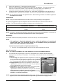
Fig 1
added to an existing installation.
NOTE: It is important that adequately sized piping runs directly to the connection joint on the
appliance, with as few tees and elbows as possible to give maximum supply volume.
9
Installation
2.
A suitable joining compound which resists the breakdown action of LPG must be used on every gas
line connection, unless compression fittings are used.
The connection to the appliance is 3/4” BSP male.
NOTE: A Manual Isolation Valve must be fitted to the individual appliance supply line.
3.
4.
5.
6.
Correctly locate the appliance into its final operating position and using a spirit level, adjust the legs
so that the appliance is level and at the correct height.
Connect the gas supply to the appliance.
Check the gas operating pressure to, as shown in the ‘Specifications’ section. If the pressure is
incorrect, adjust the pressure by adjusting the operating pressure adjusting screw of the gas control
valve as shown in the ‘Gas Conversion and Specifications’ section.
Check all gas connections for leakages using soapy water or other gas detecting equipment.
WARNING:
DO
NOT USE A NAKED FLAME TO CHECK FOR GAS LEAKAGES .
NOTE: The operating pressure is to be measured at the lower test point (Out) on the gas control
valve located behind the access door and through the access hole in the control panel, this
is to be carried out with all burners operating at the 'High Flame' setting.
I MPO RTAN T :
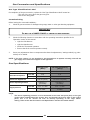
The Control Panel ‘ON' / 'OFF’ Key provides ‘ON' / 'OFF’ control of the Controller and
Main Burner heating cycles ONLY.
The Gas Valve Control Knob is used to turn ‘ON' / 'OFF’ the Gas System in conjunction
with providing Pilot Ignition and Pilot Standby functions.
7.
8.
9.
10.
11.
Turn ‘OFF’ the mains gas supply and bleed the
gas out of the appliance gas lines.
Turn ‘ON’ the gas supply and the appliance.
Verify the operating pressure remains correct
(Re-adjust if required, using the operating
pressure adjusting screw as shown in the ‘Gas
Conversion and Specifications’ section).
Check the pilot flame size. (Re-adjust if
required, using the pilot adjusting screw as
shown in the ‘Gas Conversion and
Specifications’ section).
Turn ‘ON’ to ‘Full’ settings all other gas
appliances / equipment supplied from the same
gas supply line and verify the operating
pressure remains unaffected by the maximum
gas supply demand.
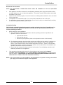
Supply Pressure
Test Point
Operating Pressure
Adjusting Screw
Pilot Burner
Adjusting Screw
Operating Pressure
Test Point
Fig 2
NOTE: Insufficient gas supply line capacity, indicated by the operating pressure drop during the
maximum gas supply demand, is NOT ACCEPTABLE and may invalidate the manufacturers
warranty for this appliance.
10
Installation
Electrical Connection
NOTE: ALL ELECTRICAL CONNECTION MUST ONLY BE CARRIED OUT BY AN QUALIFIED
PERSON.
1.
2.
3.
4.
Each appliance should be connected to an adequately protected power supply and isolation switch
mounted adjacent to, but not behind the appliance. This switch must be clearly marked and readily
accessible in case of fire.
Check that the electricity supply is correct as shown on the Rating Plate attached to the to the inside
of the access door.
The appliance is connected through a 2 m, 10 Amp flex located at the rear of the oven.
For immediate electrical supply, simply fit a plug to the flex (if a plug is not already fitted) and plug
the lead into a properly earthed, 3 pin socket.
Commissioning
The following commissioning checks must be carried out before the fryer is handed over for
use, to ensure that the appliances operates correctly and the operator(s) understand the
correct operating procedure.
1.
Before leaving the new installation;
a. Check the following functions in accordance with the operating instructions specified in the
'Operation' section of this manual.
•
Light the Pilot Burners.
•
Light the Main Burners.
•
Check the Fryer Operation (Refer to the 'Operation' section of this manual).
b. The thermostat operation check should be carried out by filling the fryer with oil / shortening to
the oil 'FILL LEVEL' mark at the rear of the tank (refer to 'Filling the Tank' in the 'Operation
Section' of the Manual) and set the thermostat temperature to 180°C. (Refer to the Controller
Programming section). Light the pilot burners and turn on the main burners in accordance with
'Operation Instructions' found in this manual.
c. Ensure that each operator has been instructed in the areas of correct lighting, operation, and
shutdown procedures for the appliance.
2.
This manual must be kept by the owner for future reference and a record of the Date of
Purchase, Date of Installation and the Serial Number of the Appliance is recorded and kept
with this manual. (These details can be found on the Rating Plate attached to the rear of
the access door. Refer to the 'Gas Connection' section).
NOTE: If for some reason it is not possible to get the appliance to operate correctly, shut off the
gas supply and contact the supplier of this appliance.
11
Operation
Operation Guide
C AUTIO N :
• This appliance is for professional use and is only to be used by qualified
persons.
• Only qualified service persons are to carry out installation, servicing or gas
conversion operations.
• Components
having adjustments protected (e.g. paint sealed)
manufacturer should not be adjusted by the user / operator.
1.
2.
by
the
BLUE SEAL 'FAST-FRI' fryers have been designed to provide simplicity of operation and 100% safety
protection.
Improper operation is therefore almost impossible, however bad operation practices can reduce the
oil / shortening life and produce a poor quality product. To use this fryer correctly please read the
following sections carefully:•
Filling the Tank.
•
Lighting the Pilot Burners.
•
Lighting the Main Burners.
•
Setting the Operating Temperature.
•
Frying Temperature Guide and Care of Oil.
•
Draining and Cleaning.
IMPORTANT
Should any abnormal operation like;
- ignition problems,
- abnormal burner flame,
- burner control problems,
- partial or full loss of burner flame in normal operation, be noticed, the appliance requires
IMMEDIATE service by a qualified service person and should not be used until such service is
carried out.
12
Operation
Description of Controls
A commercial heavy duty, gas fired Fryer using a fast fry infra red burner system and is available in 3
model types:Gas Single Pan Electronic Fryer (20 Ltr).
Gas Twin Pan Electronic Fryer (26 Ltr).
Gas Single Pan Electronic Fryer (31 Ltr).
•
All models are fitted with dual main burners and pilot burners.
•
Single tank models fitted with a single gas controller which controls both pilot and main burners.
•
Twin tank model fitted with twin gas controllers which work independently for each burner.
•
Fryers feature an Over Temperature Safety Cut Out system with Full Flame Failure Safety Controls.
•
Electronic temperature control sensitive to changes in oil temperature.
•
Open tank design for both units to simplify cleaning operation.
•
Programmable melt cycle.
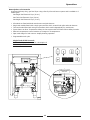
Single Tank GT45E Controls
Refer to the ‘Operation’ section for a description of
the control panel functions.
ON/OFF
O
Supply Pressure
Test Point
Gas Control
Valve
Piezo Igniter
Fig 3
13
Operation
Twin Tank GT46E Controls
ON/OFF
O
O
Fig 4
Single Tank GT60E Controls
O
ON/OFF
Flame Failure
Button
Left & Right
Piezo Igniters
Fig 5
14
Gas Control Knob
Operation
Description of the Electronic Control Panel
ON/OFF
Control Panel Functions
Each control panel comprises the following:One 4 digit, seven segment display with a 0.5” high, bright green LED display.
Three green LED indicator lights located under each of the 3 Timer Controls.
6 Touch Control Keys;ON/OFF
‘ON’ / ’OFF’ Key.
Programme Key (P).
Left Timer - ‘UP’ Key and LED indicator light.
Centre Timer - and LED indicator light.
Right Timer - ‘DOWN’ Key and LED indicator light.
The 3 Timer keys on each control
panel can be used to program 3
different cook times for each tank.
NOTE: Only one temperature
setting applies to all 3 timers.
Temperature Key (Thermostat).
Modes of Operation
The Fryer has the following Modes of Operation:• Power Up Mode.
• Melt Cycle Modes (Programmable in the Programming Mode).
• Idle Mode.
• Cook Mode.
• Temperature Display Mode.
Refer to the ‘Operation of the Appliance’ information for further details.
For Controller Programming refer to the 'System Programmable Default Settings' in the ‘Controller
Programming’ section at the rear of this manual, to access the following options:Basic Programming Mode.
- Programming the Password Protection - (Unlock Lock).
- Programming the Timers.
- Programming the Temperature.
Advanced Programming Mode.
- Timing Mode (straight or flexi time cooking).
- Temperature Offset (calibration setting) - 14° to + 14°.
- Temperature Display Mode Setting (Temp display or prompt display).
- Programming the Melt Cycle.
- Setting the Temperature Units (either °C or °F).
15
Operation
Operation of the Appliance
WARNING:
GREAT CARE MUST BE TAKEN BY THE OPERATOR TO USE THE FRYER SAFELY TO GUARD AGAINST THE RISK
OF INJURY AND FIRE.
•
DO NOT LEAVE THE FRYER UNATTENDED DURING OPERATION.
•
DO NOT REPLENISH THE OIL (FRYING MEDIUM) IN THE FRYER WHEN THE FRYER IS HOT.
•
DO NOT OVER FILL THE OIL (FRYING MEDIUM) IN THE FRYER ABOVE THE TOP LEVEL MARK.
•
DO NOT ALLOW THE OIL (FRYING MEDIUM) IN THE FRYER TO FALL BELOW THE LOWER LEVEL MARK.
•
DO NOT ALLOW THE OIL (FRYING MEDIUM) IN THE FRYER TO OVERHEAT.
•
DO NOT INTRODUCE WET FOOD OR WATER INTO THE HOT OIL (FRYING MEDIUM).
•
DO NOT USE FLAMMIBLE SOLVENTS AND CLEANING AIDS ON OR IN CLOSE PROXIMITY TO THE FRYER
WHILST THE FRYER IS STILL HOT.
I MPO RTAN T :
The Control Panel ‘ON' / 'OFF’ Key provides ‘ON' / 'OFF’ control of the Controller and
Main Burner heating cycles ONLY.
The Gas Valve Control Knob is used to turn ‘ON' / 'OFF’ the Gas System in conjunction
with providing Pilot Ignition and Pilot Standby functions.
NOTE: For Controller Programming details refer to the ‘Controller Programming’ section at the rear
of this manual.
Power-Up Mode:
1.
2.
With the mains power turned on at the mains supply, the appliance will automatically enter
the ‘OFF’ Mode. The display and alarm buzzer will remain ‘OFF’.
To turn the appliance ‘ON’, depress and release the ‘ON' / 'OFF’ key on the control panel.
Melt Cycle Active
3.
The control panel will display ‘CY’ and within 10 seconds of being turned ‘ON’ the heat
indicator (the dot to the left of the ‘CY’) will indicate burners ‘ON’ (heating).
Melt Cycle Deactive
4.
The control panel will display ‘HEAt’.
Melt Cycle Mode:
NOTE:
1.
2.
3.
4.
The only time that the appliance can enter the Melt Cycle, is immediately after
'Power-Up'.
The control panel will display ’CY’ and perform the programmed ‘Melt Cycle’ (Either ‘L’ or ‘S’
with the ‘ON/OFF’ times shown in the “Programmable Default Settings” section.
There is a minimum Melt Cycle time of 10 minutes.
After the appliance has been in the Melt Cycle for 10 minutes and the cooking medium
temperature is above the melt temperature, the system will exit the Melt Cycle.
If the Melt Cycle is programmed to OFF (O), then the appliance will not perform the Melt
Cycle and will go directly to the heat cycle and display ‘HEAt’ on the display.
Idle Mode:
1.
2.
3.
4.
After the appliance has exited the Melt Cycle Mode, or on Start-Up if the Melt Cycle Mode was
by-passed, the appliance will go to the Idle Mode.
If the temperature is more than 10° below its Set Temperature, the display will show ’HEAt’
and the heating element is ‘ON’.
When the temperature is less than 10° below its Set Temperature the display will show ‘droP’.
The appliance also displays ‘droP’ when the temperature is equal to or higher than the Set
Temperature.
16
Operation
5.
6.
7.
When the appliance displays ‘droP’ this indicates that the Fryer is ready to commence cooking
operations.
If there is a “.” displayed between the first and second characters of ‘H.EAt’ this indicates that
the heating element is ‘ON’. The appliance uses a heating rate dependent (temperature vs
time) heating algorithm.
When idling around its Set Temperature, the appliance will usually maintain a temperature
range of 5° from the Set Temperature.
Cook Mode:
NOTE:
• Each Control Panel has 3 timers for each tank, which can be programmed with
separate cook times to allow different products with different cook times to be
cooked in the same tank.
• IMPORTANT; Only one temperature can be set for all 3 timers.
• Entering the Cook Mode does not exit the melt Cycle Mode.
1.
2.
3.
4.
5.
6.
7.
8.
9.
The Cook Mode can be entered at any temperature, even when in the Melt Cycle Mode, by
pressing either the ‘1'-(Left), ‘2'-(Centre) or '3'-(Right) Timer keys, this will start the pre
programmed time set for each timer.
When only one timer is activated, the LED under the timer will blink rapidly and the time
remaining will be displayed.
When more than 1 timers are activated, the LED under the timer with the least remaining
time blinks more rapidly.
The LED's above the other active timers will blink less frequently.
When the first timer has expired and has not been cancelled the second timer’s LED turns
‘OFF’ until cancellation of the first timer.
If the second timer has not expired while the operator was cancelling the first timer, then it’s
time remaining is displayed and it’s LED will blink at the more rapidly.
When a timer expires, a beeping sound is generated and a blinking ‘L’ 'ctr' or ‘r’ is displayed
for either the left, centre or right timers respectively. This will continue until the expired
timer’s key is pressed to cancel the cooking for that timer.
An active timer may be cancelled at any time by pressing its ‘Timer’ key.
To turn the appliance ‘OFF’ depress and hold in the ‘ON/OFF’ key for approximately 3
seconds.
Temperature Display Mode:
1.
2.
3.
4.
The appliance actual temperature and set temperatures can be displayed by depressing the
Temperature Key.
If the Temperature Key is depressed the actual temperature will be displayed.
If the Temperature Key is depressed again within approximately 3 seconds, the Set
Temperature is displayed.
Further depressing of the Temperature Key will enter the Idle Mode.
NOTE: The temperatures can be checked at any time except when in the 'Program Mode'.
Before Use
1.
2.
Check that the gas supply is turned on.
Check that no foreign articles are in the tank.
WARNING:
DANGER OF FIRE EXISTS IF THE OIL LEVEL IS BELOW
17
THE MINIMUM
'LO' INDICATED
LEVEL
Operation
Filling the Tank(s)
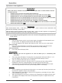
CORRECT LEVEL FOR FRYING MEDIUM
WHEN AT FRYING TEMPERATURE, KEEP
INDICATES CORRECT FRYING MEDIUM
LEVEL WHEN COLD
Fig 6
NOTE: BLUE SEAL 'FAST-FRI' fryers can be used with both oil and shortening.
1. Before filling the tank, always check that the drain valve(s) behind the door is (are) closed. A locking
slide is provided on these valves and this should always be locked in position during use.
a. OIL - Carefully fill fryer tank with oil until the 'FILL-LEVEL' mark is reached.
The GT45E fryer will hold 20 litres of oil (37lbs shortening).
The GT46E fryer will hold 13 litres of oil per tank (24lbs shortening per tank).
The GT60E fryer will hold 31 litres of oil. (46.5lbs shortening).
b. SHORTENING - Ideally shortening should be pre-melted prior to putting it into the tank. This is
normally done in a suitable vessel on a boiling table burner(s). The liquefied shortening can then be
poured into the tank until it reaches the 'FILL LEVEL' mark.
•
When pre-melting shortening, only heat until the shortening is just liquefied. Do not bring up
to high temperature as handling of hot shortening is dangerous.
•
If pre-melting of shortening is not possible then the shortening should be cut in pieces and
packed down into the tank.
•
Bringing the shortening up to frying temperature, when not pre-melting, should be done in two
stages.
i. Pre-Heating;
Light the main burners and select the melt cycle (CY) on the control panel display, the
burners will cycle ‘On’ / ‘Off’ until the shortening has liquefied.
Lighting the Pilot Burners
1.
2.
3.
4.
5.
6.
7.
8.
GT45E Fryer (Single Tank)
With the fryer tank full of frying medium, the pilot burners
can be lit.
Check that the gas supply is turned on at the mains
supply.
Open the access door at the front of the appliance to
access the control panel.
Rotate the gas control knob to the position marked 'PILOT'
and hold depressed.
At the same time hold the flame failure button depressed.
Depress the piezo igniter until the right hand pilot ignites.
Continue holding the gas control knob and flame failure
button depressed until the left hand pilot cross lights from
the right hand pilot.
Hold the gas control knob and flame failure button
depressed for approx. 10 to 15 seconds after igniting the
second pilot burner, then release, both pilot burners
should remain alight. If the pilot burners do not ignite,
repeat Items 1 to 8 above.
18
Flame Failure
Button
Gas Control Knob
Piezo Igniter
Fig 7
Operation
1.
2.
3.
4.
5.
6.
7.
8.
9.
1.
2.
3.
4.
5.
6.
7.
8.
9.
GT60E Fryer (Single Tank)
Flame Failure
Gas Control Knob
With the fryer tank full of frying medium, the
Button
pilot burners can be lit.
Check that the gas supply is turned on at the
mains supply.
Open the access door at the front of the
Left & Right
appliance to access the control panel.
Piezo Igniters
Rotate the gas control knob to the position
marked 'PILOT' and hold depressed.
At the same time hold the flame failure button
depressed.
Fig 7
Depress the right hand piezo igniter until the
right hand pilot ignites.
Continue holding the gas control knob and flame failure button depressed.
Depress the left hand piezo igniter until the left hand pilot ignites.
Hold the gas control knob and flame failure button depressed for approx. 10 to 15 seconds after
igniting both pilot burners, both pilot burners should remain alight. If the pilot burners do not
ignite, repeat Items 1 to 9 above.
GT46E Fryer (Twin Tank)
With the fryer tank full of frying medium, the pilot
burners can be lit.
Check that the gas supply is turned on at the mains
supply.
Open the access door at the front of the appliance to
access the control panel.
Rotate the right hand gas control knob to the position
marked 'PILOT' and hold depressed.
Depress the right hand piezo igniter until the right hand
pilot ignites.
Continue holding the gas control knob depressed for
approx. 10 to 15 seconds after igniting the right hand
pilot burner, the pilot burner should remain alight. If the
pilot burner does not ignite, repeat Items 1 to 6 above.
To ignite the left hand pilot burner, rotate the left hand
gas control knob to the position marked 'PILOT' and hold
depressed.
Depress the left hand piezo igniter until the left hand
pilot ignites.
Continue holding the gas control knob depressed for
approx. 10 to 15 seconds after igniting the left hand pilot
burner, the pilot burner should remain alight. If the pilot
burner does not ignite, repeat Items 7 to 9 above.
Lighting the Main Burners
1.
2.
3.
Gas Control
Valve
Right Hand
Gas Control
Piezo Igniter
Fig 8
Gas Control
Valve
Piezo Igniter
Left Hand Gas
Control Valve
Fig 9
Ensure that the pilot burners are alight, by opening the front access door of the appliance and
checking that both pilot flames are alight.
Depress and rotate the gas control knob to the ‘Full Flame’ position.
The main burners will now ignite automatically off the pilot burners.
NOTE:
• The main burners will not light if the frying medium temperature is above the
thermostat set temperature.
19
Operation
Turning ‘OFF’ the Fryer
To the ‘Pilot’ Position
a. Depress and rotate the gas control valve clockwise to the ‘Pilot’ position.
b. The main burners will extinguish and the ‘Pilot’ will remain alight.
To the ‘Off’ Position
a. Depress and rotate the gas control valve fully clockwise to the ‘Off’ position.
b. The ‘Pilot’ burners will extinguish.
c. Rotate the thermostat to the ‘O’ position.
Setting the Operating Temperature
1.
2.
3.
4.
5.
6.
7.
The temperature used for frying food is the most important aspect of fryer operation. Incorrect
temperatures will result in poor product quality and will reduce the life of the oil / shortening.
BLUE SEAL 'FAST-FRI' fryers feature a digital display electronic thermostat which is accurate to 1°C,
with a temperature range from 88°C to 193°C, although we do not recommend any food to be
cooked above 190°C.
To set the operating temperature for each timer, refer to the ’Controller Programming’ section of this
manual.
When the appliance is in ‘Cook Mode’, the main burners will operate automatically to maintain this
temperature.
In order to obtain the best results with your fryer and the product cooked in it, the following pages
detail recommended temperatures and a practical guide to frying. Time spent reading this
information will assist in obtaining a cooked product of exceptional quality and taste.
As a safety precaution all BLUE SEAL 'FAST-FRI' fryers feature an Over-Heat control which will turn
off the fryer in the event that the oil reaches over 220°C, should there be a thermostat failure.
BLUE SEAL GT46E 'FAST-FRI' Fryers feature a split tank allowing distinctive products to be cooked in
individual pans and at different temperatures. This allows seafood products to be fried separate
from French Fries for instance to stop flavour contamination between products and allow products to
be cooked at their optimum frying temperature.
Frying Guide and Care of Frying Oils and Fats.
1.
2.
3.
4.
5.
6.
7.
8.
9.
10.
Prepare the food correctly. Prepare the food in as nearly uniform pieces as possible and bring the
food up to room temperature. Ensure that the food is free from excessive moisture and also
excessive crumbing when 'breading' is done.
Preheat the frying medium to the recommended temperature for the particular food to be cooked
and no higher - specially prepared frying mediums are recommended.
The frying medium should be at the correct temperature for the food to be cooked before lowering
the food into the tank. Avoid heating the frying medium to any higher temperature than is
recommended. Also avoid holding the frying medium at the frying temperature when there is no
food being cooked. Any frying medium will break down if held for long periods at frying
temperatures.
Lower the food gradually into the hot frying medium using a wire basket, until all the food pieces are
submerged. Avoid overloading the basket, we recommend no more that 900g per basket or 1800g
per load. Overloading will cause the temperature to drop so low that a longer frying time will be
needed and the foods will become grease soaked and unattractive. With a little experience you can
determine what amount of food may be added to the fryer without causing an excessive drop in
temperature. If the temperature drop is excessive, either the food is too cold or there is too much
food in the fryer. Temperatures and cooking times quoted are based on average size batches being
used in the fryer.
Continue cooking until the outside of the food is brown and crisp and the pieces are cooked through.
The exact cooking time depends upon the size of the food pieces and upon whether the food has
been pre-cooked. When in doubt, test a sample and be sure.
Remove the food from the frying medium and allow the food to drain in the basket over the fryer.
Conserve the excess frying medium by letting it drain back into the fryer. This draining should not
consume much time if the fried food is to be served at its hot, crisp and flavoursome best.
Serve the food immediately after frying.
Deep fried foods are at their flavour peak as soon as the frying is complete. Serve them within a
minute or two after they are taken from the fryer. Fried foods should never be held.
20
Operation
Frying Temperature Guide and Care of Frying Medium
Summary of Practical Care of Frying Fats and Oils
Fats and oils are unstable compounds. Even the best oils and fats will break down to some extent in
the fryer.
There are a number of causes of frying mediums ceasing to be edible. Heat and moisture are two of
the most important causes and we have both heat and moisture in the deep well fryer.
Frying medium is by far the most expensive item of deep well frying equipment, if the following
points are carefully observed, the cost of frying can be kept to a minimum.
a. Select one of the recommend mediums for deep frying (Hydrogenated shortening, high grade
lards or salad oils made from peanuts, cottonseed or corn). Know the smoking temperature of
the one you select, generally the heat temperate qualities and stability of frying oils, particularly
peanut oil, are perhaps greater than that of the solid fats.
b. Avoid burning the medium - either when putting new medium into fryer or during frying, No
food needs a deep well frying temperature higher than 195°C and most foods should be fried
around 180°C.
c. Have rapid 'turnover' of the frying medium. The term 'turnover' means the rate at which fresh
medium is added to the old medium in the fryer.
d. Filter the frying medium daily, or more often if necessary, to remove crumbs and other sediment.
e. Clean fryer each time the medium is filtered, to keep it free from gum. Also be sure that all soap
and detergent is thoroughly removed from the fryer after cleaning it.
f. Taste the frying medium daily to be sure there is no 'Off' flavour which may be transmitted to
other foods.
If these simple precautions are taken consistently, fried foods can always be served at their delicious
best. Furthermore, the breakdown of frying medium can be kept at a minimum and the cost of frying
operations can be considerably lowered.
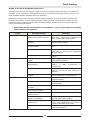
Smoking Temperatures of Frying Mediums.
Based on work by the American Meat Institute.
Medium
Hydrogenated Fats.
Compounds.
Lards - Team-rendered.
Refined deodorised lard.
Kettle-rendered.
Oils.
Corn.
Cottonseed.
Smoking Temperature
190°C to 225°C.
194°C to 223°C.
165°C to 225°C.
221°C.
190°C.
190°C.
208°C.
217°C.
Frying Temperature Chart
Please note that this chart is intended as a guide only.
Product
Chicken - Small Pieces
- Large Pieces
Chops / Cutlets
Fish Battered / Breaded
Prawns / Shellfish
Doughnuts - Cake type
- Yeast raised
Fritters
Vegetables
Potato chips - Blanch
- Fry
French Fries - Medium
- Shoe string
Temperature (°C)
175-185
160-170
165-175
170-175
170-175
185-190
175-180
175-185
185-190
165
190
190
190
21
Duration (minutes)
8-10
14-16
5-8
1-5
1-5
2
2
3-5
2-3
3-4
3-4
3-4
3-4
Cleaning and Maintenance
WARNING:
DO NOT USE FLAMMIBLE
SOLVENTS AND CLEANING AIDS ON OR IN CLOSE PROXIMITY TO THE FRYER
WHILST THE FRYER IS STILL
HOT.
C AUTIO N :
Always turn off the gas and electrical supply at the mains supply before
cleaning.
This appliance is not water proof.
Do not use water jet spray to clean interior or exterior of this appliance.
General
•
To achieve the best results cleaning must be regular and thorough and all controls and mechanical
parts checked and adjusted periodically by a qualified service person. If any small faults occur, have
them attended to promptly.
•
Don't wait until they cause a complete breakdown. It is recommended that the appliance is serviced
every 6 months.
•
Clean the fryer regularly. A clean fryer looks better, will last longer and will perform better.
NOTE:
• DO NOT use abrasive detergents, sharp scrapers, strong solvents or caustic
detergents as they could corrode or damage the fryer.
• Ensure that any detergent or cleaning material have been completely removed after
each cleaning.
To keep your fryer clean and operating at peak efficiency, follow the procedures below:Draining and Cleaning
WARNING:
DO NOT ATTEMPT TO MOVE THE FRYER WHILST THE FRYER IS FULL OF OIL.
BEFORE ATTEMPTING TO MOVE THE FRYER, ENSURE THAT ALL THE OIL HAS BEEN
DRAINED FROM THE TANK. REFER TO THE INFORMATION BELOW ON HOW TO DRAIN THE
OIL FROM THE FRYER.
C AUTIO N :
Never drain the fryer with power or burners ‘ON’
Always switch ‘OFF' the fryer before draining or re-filling the tank.
Opening the Drain Valve
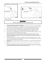
a. Lift the locking slide on valve handle (Fig 10) to release valve.
b. While holding the locking slide in the withdrawn position, rotate the handle anticlockwise (Fig 11)
to open the valve.
c. When the valve is closed, the locking slide will drop down over the locking valve to prevent
accidental opening of the valve as shown in Fig.10.
22
Cleaning and Maintenance
Locking Slide
Locking Slide
Fig 10
Fig 11
Daily Cleaning
WARNING:
HOT OIL WILL BURN - DO NOT RUSH THIS JOB.
1.
2.
3.
4.
5.
6.
7.
8.
9.
10.
11.
At the end of each day or at the end of each shift, if the frying schedule is heavy, the frying medium
should be drained and strained into a receptacle.
Always filter the fryer when the cool zone under the elements is hot and liquid. A cold fryer heated
up won't drain, because the frying medium in this zone will remain hard if using solid fat / oils.
Screw on the drain extension pipe and position a suitable container and filter under the drain.
Open the drain valve slowly to minimise splashing, and take care not to overfill the container.
Use a drain stick, if necessary, to stir up any solid medium into the top medium to melt it.
Slip a muslin or other suitable bag over the drain valve. Crumbs will be caught in the bag but frying
medium will strain freely through bag into the receptacle.
When the tank is empty, use a small tank with a handle as a ladle and dip into the hot frying
medium from receptacle and pour vigorously around sides and bottom of the tank to wash out
crumbs and particles adhering to them. Continue to dip and pour until all crumbs are washed down
and into the filter bag.
Open the drain valve fully and check for any particles or crumb residue lodged in the valve. Clean
out with a stiff nylon brush. Do not use wire brush or metal rods as these damage the seating in the
valve and will eventually lead to valve leakage.
If the obstruction in the valve cannot be removed with a brush, use a wooden probe to dislodge any
obstruction.
Clean the Control Panel with a damp cloth lightly moistened with a solution of mild detergent and
water.
Once the daily cleaning operation is completed, close the valve and pour the frying medium back
into the tank and continue the days work. Straining takes less time than frying one load of potatoes
and will pay dividends in food quality and saving of frying medium.
23
Cleaning and Maintenance
Weekly Cleaning
NOTE: If the fryer usage is very high, we recommend that the weekly cleaning procedure is carried
out on a more frequent basis.
1.
2.
Proceed as for 'Daily Cleaning' to drain and filter the tank. Do not refill the tank with frying medium
until it has been cleaned as shown below.
Fill the fryer with cold water to the normal fill level and add a high quality commercial cleaner that
has been specifically formulated for fryers. All purpose cleaners are not recommended.
NOTE: Never use a caustic or lye solution, as this will leave a fat destroying film on the tank.
3.
4.
5.
6.
7.
8.
Heat the water to approximately 80-90°C.
Clean the fryer baskets at the same time by simply immersing them in the cleaning solution. Allow
the fryer to soak for 5-10 minutes or as directed on the cleaner instructions. Remove the baskets
and turn OFF the main burners.
Scrub the baskets and fryer tank lightly, but vigorously with a stiff nylon bristle brush to remove any
remaining deposits. DO NOT use a wire brush, as this will scratch the sides.
Empty the fryer and rinse thoroughly with water. Use a 1 part vinegar to 15 parts water solution to
rinse the tank and neutralise any cleaner residue. Use a weaker solution of up to 1 part to 25 water
if this proves unsuitable for the cleaner being used.
Rinse the tank thoroughly with water, drain and dry.
Refill the tank with new filtered frying medium.
Stainless Steel Surfaces
a. With the tank(s) drained, cleaned and dried as shown above, clean the exterior surfaces of the
fryer with hot water, a mild detergent solution and a soft cloth. Clean the Control Panel with a
damp cloth lightly moistened with a solution of mild detergent and water.
b. Note that the gas control knobs are a push fit onto the gas control valve spindles and can be removed to allow cleaning of the front control panel.
c. Dry all components thoroughly with a dry cloth and polish with a soft dry cloth.
d. To remove any discolouration, use an approved stainless steel cleaner or stainless steel wool.
Always rub in the direction of the grain.
Periodic Maintenance
WARNING:
DO NOT ATTEMPT TO MOVE THE FRYER WHILST THE FRYER IS FULL OF OIL.
BEFORE ATTEMPTING TO MOVE THE FRYER, ENSURE THAT ALL THE OIL HAS BEEN
DRAINED FROM THE TANK. REFER TO THE INFORMATION ON THE PREVIOUS PAGES ON
HOW TO DRAIN THE OIL FROM THE FRYER.
NOTE: All maintenance operations should only be carried out by a qualified service person.
To achieve the best results cleaning must be regular and thorough and all controls and mechanical parts
should be checked and adjusted periodically by a qualified service person. If any small faults occur, have
them attended to promptly. Don't wait until they cause a complete breakdown. It is recommended that
the appliance is serviced every 6 months.
24
Fault Finding
Guide to Cooking Problems with Fryer
This section provides an easy reference guide to the more common problems that may occur during the
operation of your equipment. The fault finding guide in this section is intended to help you correct, or at
least accurately diagnose problems with your equipment.
Although this section covers the most common problems reported, you may encounter a problem not
covered in this section. In such instances, please contact your local authorised service agent who will
make every effort to help you identify and resolve the problem. Please note that the service agent will
require the following information:• Model Code and the Serial Number of the appliance. (both can be found on the Rating
Plate located on the appliance.
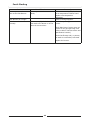
Fault
Possible Cause
Remedy
Frying medium foaming.
Presence of soap or detergent
residue from cleaning the tank.
Rinse the fryer thoroughly three times with
clean water. Ensure fryer is perfectly dry
before re-filling with frying medium.
Excessive breakdown of frying
medium.
Add fresh frying medium daily to replace
contents every 3-5 days.
Continual frying of food with
excess moisture.
Remove excess moisture from foods to be
fried.
Continued overheating of oil.
Check setting of the thermostat. Turn
down heat to around 120°C (Standby)
when use is quiet
Overloading.
Maintain 1-8 ratio of food to frying
medium.
When charging fryer or starting up, melt
frying medium gradually.
Gumming.
Greasy foods.
Heating
rapidly.
frying
medium
too
Continued overheating of the
frying medium.
Check the thermostat setting by using a
'Mercury In Glass' thermometer or
thermocouple.
Frying oil broken down.
Check amount of fresh frying medium
added to fryer to be sure 'turnover' is
adequate.
Some frying mediums form gums when
used in a deep fryer. e.g safflower oil.
Increase temperature and check
thermostat setting.
Be sure foods (especially potatoes) are
'cured' correctly.
Remove surplus breading or batter.
Using wrong cooking frying
medium.
Frying at too low temperatures.
Inadequate preparation of food.
Excessive quantities of breading
or batter.
Placing food in frying medium
direct from the freezer.
Surplus moisture in and on
surface of food.
Frying medium in advanced
stages of breakdown.
Use of dripping or other
unrefined oil.
Using the wrong kind of cooking
oil.
25
Allow frozen foods to thaw before frying.
Drain and dry foods before frying.
Discard 'old' frying medium and refill the
fryer with new cooking medium.
Due to low smoking point, cooking in these
oils at lower temperatures will result in
greater oil absorbtion by the food.
Always use a completely refined and
deodorised cooking oil.
Fault Finding
Fault
Rapid oil breakdown.
Possible Cause
Remedy
Inadequate frying oil turnover.
Adjust procedures to fry more food in the
fryer to increase the turnover.
Overheating of oil.
Check the setting of the thermostat with a
'Mercury In Glass' thermometer or
thermocouple.
Filter or strain the oil daily.
Contamination.
Poor cleaning procedures.
Oil smoking.
Presence of copper or brass in the
fryer equipment.
Overloading fryer.
Clean the fryer each day or at least once a
week and rinse thoroughly. Dry the fryer
before use.
Remove all copper or brass fittings from
contact with the oil.
Maintain 1-8 ratio of food to frying oil.
Food excessively moist.
Overheating oil on ‘Standby’
mode.
Drain and dry the food before frying.
Reduce temperature of frying oil between
93°C during idle (‘Standby’) periods.
Insufficient turnover of oil.
Maintain a minimum quantity of oil in the
fryer for more rapid turnover or increase
the quantity of food fried in the fryer.
Replace with fresh oil every 3 to 5 days.
Drain foods before frying, pat food dry.
Continual frying with
moisture on food.
Contamination of oil.
excess
Filter or strain daily to remove
contaminants.
Check the setting of the thermostat with a
'Mercury In Glass' thermometer or
thermocouple.
Use stable frying oil.
Overheating of oil.
Rapid breakdown of oil.
Darkening of oil.
Use of unrefined oils.
Dripping smokes at lower temperature than
refined and deodorised oils.
Presence of salt on the food.
Salt foods after frying and away from the
fryer.
Reduce egg content of the batter, replace
part egg with milk.
Filter or strain oil daily to remove contaminants.
Clean the fryer at least once a week or
each day in cases of heavy usage. Ensure
fryer is perfectly dry before use.
Check the setting of the thermostat with a
'Mercury In Glass' thermometer or thermocouple.
Foods dipped in batter high in
egg yolk.
Contamination of oil.
Poor cleaning practice.
Overheating of oil.
Insufficient oil turnover.
Cooking foods with high sugar
levels.
Top up daily to replace the contents of fryer
in 3 to 5 days.
Potatoes at the end of a season are usually
high in reduced sugars. When fried, they
will darken quickly and colour the oil.
NOTE: Excessive usage of oil is an indication of high absorption of oil into the food. This is a
function of temperature and character of the goods being fried - NOT due to the type of oil
being used (unless refined oils are being used). Any variation in the apparent life of the oil
is always due to one or more of the causes mentioned above.
26
Fault Finding
Fault Finding the Gas System
Fault
Pilot Burners will not light /
stay alight.
Possible Cause
Check gas supply is turned on.
Check gas supply is low or empty.
Thermocouple connection loose.
Over temperature lead connection
to interrupter on thermocouple is
loose.
Loose connections will
cause resistance to millivolt circuit
and result in pilot outage.
Pilot Burner delay in ignition
of main burners.
Remedy
Turn on gas supply.
Replenish gas supply.
Tighten thermocouple connection.
Replace any damaged connectors.
Tighten over temperature lead to the
interrupter on the thermocouple.
If sufficient pilot flame cannot be
obtained, remove pilot orifice
from pilot burner and check for
blockage of the pilot burner and /
or correct size.
If connections OK, check for gas at
the pilot burner by manually lighting
the pilot burner.
If pilot can be lit but flame too
small to impinge on the
thermocouple.
Check adjustment of pilot flow by
adjusting screw below control knob
on gas control. Check the supply.
If pilot flame OK but goes out
after control knob released (after
holding in for approx. 30 secs).
Check for faulty thermocouple or
over temperature thermostat.
Call service provider.
Check the oil temperature. If
above 205°C, the over
temperature will be open circuit.
Wait for oil to cool to approximately
190°C and re-light pilot burner. If
overtemp is operating OK the pilot
should now stay alight.
Check the oil temperature, if the
oil is cold, disconnect the
thermocouple from the gas
control, while holding in the
control knob in the pilot position
and using a multimeter measure
the millivolts being generated
between the thermocouple end
and earth (place other probe of
multimeter on body of gas
control).
If no millivolts generated,
disconnect overtemperature
thermostat leads from interrupter
terminal on thermocouple and
check continuity through
overtemperature thermostat with
multimeter.
If all of the above in the pilot and
thermocouple system checks out
satis. but the problem still
persists.
Check operating pressure as
stated in ‘Installation’ section.
Check pilot flame adjustment.
With the thermocouple hot, millivolt
reading should be between 20-30
mV. If voltage reading below 15
millivolts the thermocouple is
defective. Replace the
thermocouple.
27
If overtemperature thermostat is
open circuit it is faulty and needs
replacing.
If there is continuity through over
temperature thermostat then
thermocouple is faulty and needs
replacement.
The gas control valve is defective
and needs replacement.
I n c r e a s e b y a dj u s t i n g p i l o t
adjustment screw on gas control.
Pilot flame for main burner ignition
should be approximately 1 inch long.
Check pilot burner size is correct.
(See 'Specifications' section).
Fault Finding
Fault
Over temperature thermostat
cuts out the Pilot Burners.
Possible Cause
Overtemperature thermostat is
faulty.
Main Burners do not light.
Main Burners Do Not Burn
Correctly.
Remedy
If thermostat cutting out pilot when
the oil temperature is below 200°C.
Replace over temperature
thermostat.
Refer to ‘Wiring Diagrams’.
Burners roar, light back through
the mesh to the burner or do not
burn the correct colour.
Check the operating pressure is
correct.
Check Main Burner Injector sizes are
correct for the gas type being used.
(refer to table in 'Gas Conversion and
Specifications' section).
Check that flueway and / or primary
air intake is not blocked / restricted.
Replace the burners.
28
29
N
P
FLAME FAILURE VALVE
SIT M1/A
L.H. PILOT T/C
TRANSFORMER
24v
CROSS LIGHTING
FUSE
2.0 Amp
R.H. PILOT
T/C
'FAST' DIGITAL
CONTROLLER
OVER TEMP
THERMOSTAT
PROBE
IGNITION
MAIN GAS
CONTROL
SIT NOVA 820mV
24V 50Hz
Wiring Schematics
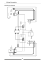
GT45E Fryer Schematic
IGNITION
TH
MAIN GAS
CONTROL
SIT NOVA 820mV
24v 50Hz
PILOT
TC
30
N
P
TRANSFORMER
24v
'FAST' DIGITAL
CONTROLLER
OVER TEMPS.
THERMOSTAT
PROBE
FUSE
2.0 Amp
PILOT
'FAST' DIGITAL
CONTROLLER
T/C
MAIN GAS
CONTROL
SIT NOVA 820mV
24v 50Hz
IGNITION
Wiring Schematics
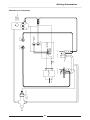
GT46E Fryer Schematic
FLAME FAILURE VALVE
SIT M1/A
31
P
N
L.H. PILOT T/C
TRANSFORMER
24v
FUSE
2.0 Amp
R.H. PILOT
T/C
THERMOSTAT
PROBE
IGNITION
'FAST' DIGITAL
CONTROLLER
OVER TEMP
IGNITION
MAIN GAS
CONTROL
SIT NOVA 820mV
24V 50Hz
Wiring Schematics
GT60E Fryer Schematic
Controller Basic Programming Mode
Controller Basic Programming Mode:
NOTE:
• 'Timer 1', 'Timer 2' and ‘Timer 3' keys on each control panel can be programmed with
3 different cook times for each tank.
• The user may not enter Programming Mode whilst a timer is running. An alarm will
sound indicating the key press, but the unit will not go to the Programming Mode.
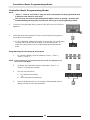
1.
To enter the ‘Programming Mode’, press the ‘ON / OFF’ key to turn ‘ON’ the
appliance.
2.
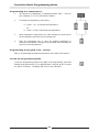
Continually press the Programme ‘P’ key to cycle through the programs to
the program to be changed.
a. If ‘LoC’ is displayed, password protection is turned ‘ON’, the control panel
is locked which, will prevent any change to the operating mode. To
unlock the control panel, refer to 'Programming Password Protection'
below.
Programming the Password Protection
1.
To unlock the display, enter the password 'Timer 1', 'Timer 1',
'Timer 3', 'Timer 3'.
NOTE: If the password is not entered within 6 seconds, the appliance will
return to the Idle Mode.
2.
To change the ‘Password Protection’ press either 'Timer 1', or
'Timer 3', to change the selection.
3.
The user may select from,
a. ‘Loc’ (Password protected).
Or
b. ‘ULoc’ (No password protection).
4.
Press the Programme Key ‘P’, the change will be accepted and the
display will step on to the next parameter.
32
Controller Basic Programming Mode
Programming the Timers
1.
To change the settings, press either 'Timer 1', or 'Timer 3', to change
the selection.
2.
Press the Programme Key ‘P’ to enter the ‘Programme Mode’.
3.
Once in the ‘Programme Mode’ the following options can be cycled
through by pressing the Programme Key again.
NOTE: If only one parameter is to be changed, cycle through the parameters by depressing the
Programme ‘P’ key to the desired parameter, change the parameter and then press and hold
down the Programme ‘P’ key for approximately 3 seconds, the display will return to the ‘Idle
Mode’.
'Timer (1)’.
1.
The user access's 'Timer 1’ immediately upon entering ‘Programme
Mode’.
2.
The stored time is displayed (Default; 3:00) with flashing colon and
the LED indicator below 'Timer 1’ remains ‘ON’.
3.
To change the time, press either;
a. 'Timer 1 - Up ’ to increase the time.
Or
b. 'Timer 3 - Down' to decrease the time.
4.
When changing the time, the value changes at a slow rate for the first
10 seconds and then at an increased rate.
5.
Press the Programme Key ‘P’ once the desired time is reached, the
time change will be accepted and the display will step on to the next
parameter.
'Timer (2)’.
'Timer 2’ behaves the same as 'Timer 1’ shown above.
'Timer (3)'.
'Timer (3)’ behaves the same as the 'Timer 1’ shown above.
33
Controller Basic Programming Mode
Programming the 'Temperature'.
1.
The stored set ‘Temperature’ is displayed (default 350°F - 176.5°C)
with a flashing ‘F’ or ‘C’ for Fahrenheit or Celsius.
2.
To change the temperature, press either;
a. 'Timer 1 - Up ’ to increase the temperature.
Or
b. 'Timer 3 - Down' to decrease the temperature.
3.
When changing the temperature, the value changes at a slow rate for
the first 8 degrees and then at an increasing rate.
4.
Press the Programme Key ‘P’ once the desired temperature is
reached, the temperature change will be accepted and the display will
step on to the next parameter.
Programming the Keypad 'Lock - Unlock’.
Refer to 'Programming the Password Protection' at the start of this section.
To Exit the Programming Mode.
To exit the Programming Mode at any stage of the programming, press and
holding the Programme Key ’P’ for approximately 3 seconds, or do not press
any key for 2 minutes. The display will revert to the ‘Idle Mode’.
34
Controller Advanced Programming Mode
Controller Advanced Programming Mode:
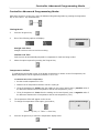
With power turned on to the fryer, enter the Advanced Programming Mode by pressing the Programme
Key ‘P’ and 'Timer 1' key simultaneously.
Timing Mode
3.
Press the 'Program' key.
4.
One of the following options will display:-
Factory Default Settings
Straight Cook Time
Straight cook time refers to real time cooking.
Flexible Cook Time
Cook time can be automatically adjusted to compensate for load size being cooked.
5.
Select the option required by pressing the 'Program' key.
Temperature Offset
To calibrate the thermostat control of the display temperature in relation to the oil temperature, the
display temperature can be adjusted by between -14° to +14°.
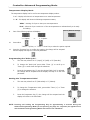
To Calibrate the Control Temperature
6.
7.
•
Set the control temperature to 170°.
•
Measure the oil temperature that the control is cycling at.
•
If the oil temperature is higher than the reading on the control panel, enter a positive value of
the difference between the oil temperature and the set temperature (170°).
•
If the oil temperature is lower than the reading on the control panel, enter a negative value of
the difference between the oil temperature and the set temperature (170°).
The temperature offset will appear on the screen.
To change the temperature offset option, press either;
Factory Default Settings
O°
'Timer 1 - Up’ key or 'Timer 3 - Down' key.
8.
Press the 'Program' key to select the temperature display mode.
35
Controller Advanced Programming Mode
Temperature Display Mode
The temperature display can be set for two temperature display modes:-
't -1’ - Display will show the oil temperature as an actual temperature.
’t - 0’ - The display will show the following temperature status;
‘HEAt’ - Awaiting for fryer to heat up to set temperature.
‘droP’ - When the fryer is within 10° of the set temperature to indicate that fryer is ready
for loading.
9.
‘t -0’ Option
10.
Factory Default Settings
One of the following options will display:-
or
‘t -1' Option.
Press either
'Timer 1 - Up’ key or 'Timer 3 - Down' key to select the option required.
11.
Press the 'Program' key to confirm the options, the change will be accepted
and the display will step on to the next parameter.
Programming the ‘Melt Cycle’.
1.
The user may select from ‘L’ (Liquid), ‘S’ (Solid) or ‘O’ (Override).
2.
To change the ‘Melt Cycle’ press either ‘Timer (1)' to scroll up or
'Timer (3)' to scroll down through the selections.
3.
Press the Programme Key ‘P’ once the desired ‘Melt Cycle’ is selected,
the change will be accepted and the display will step on to the next
parameter.
Setting the ‘Temperature Units’.
1.
The user may select from ‘F’ (Fahrenheit) or ‘C’ (Celsius).
2.
To change the 'Temperature Units', press either ‘Timer (1)' or 'Timer
(3)' to change the selection.
3.
Press the Programme Key ‘P’, the change will be accepted and the
display will revert to the ‘Idle Mode’.
NOTE: Pressing and holding the Programming Key for approximately 3 seconds during the
Advanced Programming Mode (Or not pressing any keys for 2 minutes) the appliance will
exit the Advanced Programming Mode and return to the ‘Idle Mode’.
36
Controller Advanced Programming Mode
System Programmable Default Settings
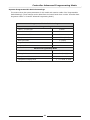
This section shows the system parameters for this model and contains a table of the ‘Programmable
Default Settings’, (These settings can be edited from the Control Panel when in either ‘Controller Basic
Programme Mode’ or 'Controller Advanced Programming Mode').
Programmable Default Settings
Basic Programming Mode
Timer 1 ‘L’ Cook Time
3:00min
Timer 2 'Ctr’ Cook Time
3:00min
Timer 3 'R’ Cook Time
3:00min
Temperature Set Point
177°C (350°F)
Melt Cycle Mode
L (Liquid)
Keypad Lock or Unlock
Unlock
Degrees; °F or °C
°C
Advanced Programming Mode
Number of Product Timers
3
Timing Mode
S.t (Straight)
Temperature Offset
0°
Temperature Display Mode
t. -0 = 'HEAt' or 'droP'
37
Gas Conversion and Specifications
Conversion Procedure
C AUTIO N :
Ensure the appliance is isolated from the gas supply before commencing
servicing.
NOTE:
• These conversions should only be carried out by qualified service persons.
connections must be checked for leaks before re-commissioning the appliance.
All
• Adjustment of components that have adjustments / settings sealed (e.g. paint sealed)
can only be adjusted in accordance with the following instructions and shall be
re-sealed before re-commissioning this appliance.
• For all relevant information and specifications refer to the table at the end of this
section.
• Flexible Hose Connection;
If a Gas Hose assembly is used to connect this appliance, the hose and all fittings must have a
minimum ¾” (Natural Gas) or ½” (LPG) inside bore diameter to ensure gas flow rate capacity
required by this appliance is achieved.
This must be verified by the operating pressure testing at the maximum gas supply demand
condition.
The Gas Hose assembly should also be classified for use in the commercial kitchen conditions, the
appliance will be used in.
Recommended Gas Hose Assembly Specification:
- AS/NZS 1869 Class B or D compliant or equivalent, that meets the following requirements:-
1.
2.
3.
Class
Max Working Pressure
at 23 ± 2ºC
B
7.0 kPa
D
2.6 MPa
Ensure that the gas supply has been turned off.
Open the front door of the unit to access the
main burner and pilot burner injectors.
Connect a manometer to the upper test point
(Supply Pressure) on the gas control valve
located through the access hole in the
enamelled control panel. Ensure that the
supply pressure is within the specification
shown in the ‘Gas Specifications Table’ at the
end of this section.
Working Temperature Range
Resistance to Oil
- 20ºC to + 125ºC
Oil resistant
lining and cover.
Supply Pressure
Test Point
Operating Pressure
Adjustment
Pilot Burner
Adjusting Screw
Operating Pressure
Test Point
Fig 12
38
Gas Conversion and Specifications
Main Burner Injectors
1.
2.
3.
Main Burner
Injector
Unscrew and remove the main burner injectors (12.7 mm
A/F) located in front of main burner venturi openings.
Determine the correct injectors for the corresponding gas
from the ‘Gas Specifications Table’ at the end of this
section.
Screw in the correct sized injectors. Refer to the ‘Gas
Specifications Table’ at the end of this section.
Pilot Burner Injectors
1.
2.
3.
4.
5.
To prevent damage to the 2 piezo ignition electrodes,
unscrew and remove the electrodes from the mounting
brackets.
Unscrew the pilot supply tubes from both pilot burners
and remove the pilot injectors.
Determine the correct sized pilot injectors for the
corresponding gas from the table below.
Fit the correct sized injectors into the pilot burners and
re-connect the gas supply tubes to both pilot burners.
Refit the 2 piezo ignition electrodes to the mounting
brackets and tighten hand tight.
Fig 13
Pilot Burner
Thermocouple
Piezo Igniter
Fig 14
Gas Controller
NOTE: For Twin Tank Fryers only, the units will be fitted with 2 gas controllers. These controllers
operate independently of each other. The gas regulators and pilot adjustment will need to
be carried out separately for each gas controller.
Main Burner Operating Pressure Adjustment
a. Connect a manometer to the lower test point (Burner Pressure) on the gas control valve located
through the access hole in the control panel.
b. Remove the slotted cap located directly below the main gas control knob on the gas control
valve, this will reveal an operating pressure adjusting screw.
c. Light the main burners and adjust the adjusting screw to obtain the correct burner pressure for
the type of gas being used. Refer to the specification table shown at the end of this section.
d. Refit the slotted cap to the screw adjustment point.
Pilot Burner Flame Adjustment
a. Once the main burner operating pressure has been set, the pilot burner supply can be adjusted
so that impingement of the pilot flame on the thermocouple is correct and the main burner pilot
flame ignites the main burners satisfactorily.
b. Adjust the pilot flame size by adjusting the pilot burner adjusting screw on the lower right side of
the gas control valve, below the gas control knob. (Refer to Fig 12).
c. Adjust this screw so that the flame impingement on the thermocouple is correct and that the
flame of the pilot burner is approximately 1" long for main burner ignition. Anti-clockwise
rotation of the adjustment screw will increase the size of the pilot flame. (Refer to Fig 12).
On completion of the main and pilot burner adjustments, check all gas connections for leakages and then
turn off the main burners at the gas control knob. Turn off the main gas supply.
WARNING:
DO NOT USE A NAKED FLAME
39
TO CHECK FOR GAS LEAKAGES.
Gas Conversion and Specifications
Gas Type Identification Label
On completion of the gas conversion, replace the 'Gas Type Identification Label' located at:- The rear of the unit, above the gas entry port.
- Next to the rating plate.
Commissioning
Before leaving the converted installation;
1.
Check all gas connections for leakages using soapy water or other gas detecting equipment.
WARNING:
DO NOT USE A NAKED FLAME
2.
TO CHECK FOR GAS LEAKAGES.
Check the following functions in accordance with the operating instructions specified in the
'Operation' section of this manual.
3.
•
Light the Pilot Burners.
•
Light the Main Burners.
•
Check the Thermostat operation.
•
Ensure that all the controls operate correctly.
Ensure any adjustments done to components that have the adjustments / settings sealed (e.g. paint
sealed) are re-sealed.
NOTE: If for some reason it is not possible to get the appliance to operate correctly, shut off the
gas supply and contact the supplier of this appliance.
Gas Specifications
Natural Gas.
(G20)
LP Gas (Propane)
(G31)
Ø 3.10 mm
Ø 1.90 mm
Non-UK
0.62
0.35
UK Only
0.45
0.30
Full out (CCW)
1½ turns out (CCW)
0.98 kPa (*)
(9.8 mbar)
2.50 kPa (*)
(25 mbar)
Non-UK
1.13 - 2.0 kPa
2.75 - 3.0 kPa
UK Only
20 mbar
37 mbar
Main Burner Injectors
Pilot Burner Injectors
Pilot Screw Adjustment
Burner Operating Pressure
Supply Pressure
NOTE:
*
The burner operating pressure is to be measured at the lower test point (Out) on the gas
control valve located behind the access door and through the access hole in the control
panel, this is to be carried out with all burners operating at the 'High Flame'
setting. Refer to the ‘Gas Conversion and Specification’ Section for further details.
40
Replacement Parts List
Replacement Parts List
IMPORTANT:
Only genuine authorized replacement parts should be used for the servicing and
repair of this appliance. The instructions supplied with the parts should be followed
when replacing components.
For further information and servicing instructions, contact your nearest authorized
service branch (contact details are as shown on the reverse of the front cover of this
manual).
When ordering spare parts, please quote the part number and the description as listed below. If the part
required is not listed below, request the part by description and quote model number and serial number
which is shown on the rating plate.
Gas System
018094
227865
018093
Thermocouple Interrupted - Main Gas Valve.
Thermocouple - Flame Failure Valve.
Thermopile.
032190
032300
Main Burner Injector
Main Burner Injector
018090
Pilot Burner (Special) - (No Injector - includes electrode).
018971
018972
018091
018092
Pilot
Pilot
Pilot
Pilot
228617
229158
229159
019237
018095
227508
022575
018022
Gas Control Valve 24V
Gas Valve Cable / Plug 24V.
Gas Valve Cable / Plug 24V.
Flame Failure Valve.
Piezo H.T. Lead 0.5m long.
Piezo Ignitor.
Burner Kit.
Overtemperature Thermostat.
Injector
Injector
Injector
Injector
(LPG)
(Nat)
(LPG / Propane)
(Nat)
(Nat)
(LPG)
Electrical System
020117
228660
229033
020109
228707
230101
025948
025951
Temperature Probe.
Transformer 24Vac.
Fuse Holder
Fuse 2 Amp.
Digital Controller.
Controller Overlay (3 Basket).
Terminal Block - 6 Way.
Terminal Block - 3 way.
41
Ø 1.90 mm.
Ø 3.10 mm.
0.30.
0.45.
0.62
0.35
(UK Only).
(UK Only).
(Non UK).
(Non UK).
(Nova).
(GT45E / GT46E Only).
(GT60E Only).
(GT45E / GT60E Only).
Replacement Parts List
General
018019
227856
227449
227459
018358
018147
018176
228576
228577
228578
228419
228575
229674
227850
Basket.
Door Magnet.
Door Handle.
Door Handle.
Drain Valve.
Drain Extension.
Drain Stick.
Basket Tray.
Basket Tray.
Basket Tray.
Lid.
Lid.
Rear Roller Assy.
Leg 150 mm - Adjustable.
(GT45E / GT46E).
(GT60E).
(GT45E).
(GT46E).
(GT60E).
(GT45E / GT46E).
(GT60E).
Gas Conversion Kits
Gas Type to Convert to:
Model
Australia / New Zealand Only
Nat. Gas
GT45E
GT46E
GT60E
231963
LPG
Butane
231962
Accessories
228793
228794
450 mm (Fryer) Plinth Kit.
600 mm (Fryer) Plinth Kit.
42
231964
UK Only
Nat. Gas
231967
LPG
231966