1
Fuel Systems for LPG and
Natural Gas Engines
Fuelock Filters
Regulators
& Vaporizers
Mixers &
Carburetors
Product
Catalog
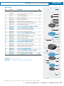
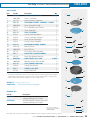
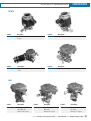
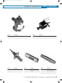
Woodward’s Streamline™ fuel system products are easy to select
and easy to use. A broad selection of Streamline mixers, carburetors,
regulators, vaporizors, and fuelocks cover a wide range of gaseous
engine applications, from 50 to 400 horsepower.
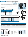
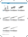
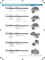
Mixers & Carburetors
Streamline™ mixers are a simple, air-valve design
that draws fuel into the mixer consistently across the
engine operating range, from cranking to full load.
That consistency assures reliable starts, smooth
off-idle progression and repeatable performance even
under extreme operating conditions.
With the engine stopped, fuel is sealed off within the
carburetor as well as the converter and fuelock,
giving a triple seal for safety. The mixer is completely
self-contained. It requires no linkage or idle vacuum
line to the intake manifold, and allows tremendous
installation flexibility. We can add throttle body and
air horn to provide you with a complete carburetor
assembly, such as the N-CA55-500, N-CA100 and
N-CA125 Series carburetors.
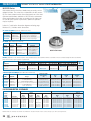
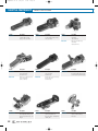
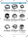
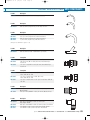
Fuelock Filters
Streamline™ N-VFF30 Series fuelock filters are
used with high-pressure LPG vapor or liquid
withdrawal systems where dependable fuel shut off
is required. The vacuum-operated lockoffs are
designed for minimal engine vacuum activation, and
the integrated filter removes foreign materials from
the fuel.
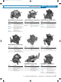
Regulators & Vaporizers
Streamline™ regulators and vaporizers are available
in a range of sizes and types to cover most propane
and natural gas fuel control requirements.
TABLE OF CONTENTS
WOODWARD
Fuel System Products
PRODUCT LINE OVERVIEW
. . . . . . . . . . . . . . . .2-5
FUEL LOCKOFFS & FILTERS . . . . . . . . . . . . . . . .4-7
N -VFF-30 Vacuum Fuelock Filter . . . . . . . . . . . . . . . . . .4-5
Fuel Lock . . . . . . . . . . . . . . . . . . . . . . . . . . . . . . . . . . . . .6-7
REGULATORS & VAPORIZERS . . . . . . . . . . . . . .8-30
N-LPR Vapor Regulator . . . . . . . . . . . . . . . . . . . . . . . . . .8-9
N-51 Vapor Regulator . . . . . . . . . . . . . . . . . . . . . . . . .10-11
N-PJ Vapor Regulator . . . . . . . . . . . . . . . . . . . . . . . . .12-13
N-H420-NG Vapor Regulator . . . . . . . . . . . . . . . . . . . .14-15
N-J Regulator . . . . . . . . . . . . . . . . . . . . . . . . . . . . . . .16-17
N-2001 Regulator/Vaporizer . . . . . . . . . . . . . . . . . . . . .18-19
N-E Regulator . . . . . . . . . . . . . . . . . . . . . . . . . . . . . . .20-21
N-H420 Regulator . . . . . . . . . . . . . . . . . . . . . . . . . . . .22-23
N-H420 Turbo . . . . . . . . . . . . . . . . . . . . . . . . . . . . . . .24-25
N-S Regulator . . . . . . . . . . . . . . . . . . . . . . . . . . . . . . .26-27
N-L Regulator Repair Kit . . . . . . . . . . . . . . . . . . . . . . . . . .28
Model N-IMP Reduction Valve . . . . . . . . . . . . . . . . . . . . .29
Flow Capacity Chart . . . . . . . . . . . . . . . . . . . . . . . . . . . . .30
CARBURETORS . . . . . . . . . . . . . . . . . . . . . . .31-51
Model N-CA55-500 Series . . . . . . . . . . . . . . . . . . . . . .32-33
Model N-CA70 Series . . . . . . . . . . . . . . . . . . . . . . . . . .34-35
Model N-CA100 Series . . . . . . . . . . . . . . . . . . . . . . . . .36-37
Model N-CA 125 Series . . . . . . . . . . . . . . . . . . . . . . . .38-39
Model N-CA200 Series . . . . . . . . . . . . . . . . . . . . . . . . .40-41
Model N-CA225 Series . . . . . . . . . . . . . . . . . . . . . . . . .42-43
Model N-CA300 Series . . . . . . . . . . . . . . . . . . . . . . . . .44-45
Model N-CA475 Series . . . . . . . . . . . . . . . . . . . . . . . . .46-47
Custom Fit Carburetors . . . . . . . . . . . . . . . . . . . . . . . .48-51
FORKLIFT KITS . . . . . . . . . . . . . . . . . . . . . . .77-87
Introduction . . . . . . . . . . . . . . . . . . . . . . . . . . . . . . . . .77-78
Caterpillar . . . . . . . . . . . . . . . . . . . . . . . . . . . . . . . . . . . . .79
Clark . . . . . . . . . . . . . . . . . . . . . . . . . . . . . . . . . . . . . .80-81
Datsun/Nissan . . . . . . . . . . . . . . . . . . . . . . . . . . . . . . . . . .82
Hyster . . . . . . . . . . . . . . . . . . . . . . . . . . . . . . . . . . . . . . . .83
Komatsu/Mistubishi . . . . . . . . . . . . . . . . . . . . . . . . . . . . . .84
Toyota . . . . . . . . . . . . . . . . . . . . . . . . . . . . . . . . . . . . . . . .85
Yale . . . . . . . . . . . . . . . . . . . . . . . . . . . . . . . . . . . . . . . . . .86
Universal Kits . . . . . . . . . . . . . . . . . . . . . . . . . . . . . . . . . .87
TECHNICAL INFORMATION . . . . . . . . . . . . . .88-118
Typical Forklift Schematic . . . . . . . . . . . . . . . . . . . . . .88-89
Automotive Duel Fuel Schematic . . . . . . . . . . . . . . . . .90-93
Stationary Engine Schematic . . . . . . . . . . . . . . . . . . . .94-95
Stationary Engine Dual Fuel Schematic . . . . . . . . . . . .96-97
Standard Dual Fuel Wiring W/ Vacuum, Lift . . . . . . . . . . . .98
3-way Vacuum Control Solenoid Duel Fuel Operation . . . .99
Air-Valve Diaphragm Installation . . . . . . . . . . . . . . . . . . .100
Fuel Characteristics . . . . . . . . . . . . . . . . . . . . . . . . .101-102
LPG Fuel Tanks . . . . . . . . . . . . . . . . . . . . . . . . . . . . . . . .103
Carburetor Selection Chart . . . . . . . . . . . . . . . . . . . .104-105
Carburetor Position/Bolt Spacing . . . . . . . . . . . . . . .106-107
Fuel System Adjustment . . . . . . . . . . . . . . . . . . . . . . . . .108
Preliminary Engine Inspection Before Conversion . . .109-110
Ignition Modifications for LP-Gas . . . . . . . . . . . . . . .111-113
Engine Starting Problems . . . . . . . . . . . . . . . . . . . . . . . .114
Maintenance Suggestions & Checks . . . . . . . . . . . . . . . . 115
Return Goods Authorization Procedures . . . . . . . . . . . . .116
Order Form . . . . . . . . . . . . . . . . . . . . . . . . . . . . . . . . . . .117
Product Warranty . . . . . . . . . . . . . . . . . . . . . . . . . . . . . .118
COMPONENTS . . . . . . . . . . . . . . . . . . . . . . . .52-76
Throttle Components . . . . . . . . . . . . . . . . . . . . . . . . . .52-54
Air Flow Components . . . . . . . . . . . . . . . . . . . . . . . . . .55-56
Hoof Governors . . . . . . . . . . . . . . . . . . . . . . . . . . . . . . . . .57
Century & Zenith . . . . . . . . . . . . . . . . . . . . . . . . . . . . . . . .58
Primers & Thermostats . . . . . . . . . . . . . . . . . . . . . . . . . . .59
Model Microvac N-1501L Vacuum Safety Switch . . . . .60-61
Switches & Gauges . . . . . . . . . . . . . . . . . . . . . . . . . . .62-63
Hours Meters . . . . . . . . . . . . . . . . . . . . . . . . . . . . . . . . . .64
Low Fuel Warning Light . . . . . . . . . . . . . . . . . . . . . . . . . . .65
Hose Components . . . . . . . . . . . . . . . . . . . . . . . . . . . .66-69
Brass Fittings . . . . . . . . . . . . . . . . . . . . . . . . . . . . . . . . . .70
Bulkheads, Inline Filters & Sealants . . . . . . . . . . . . . . . . .71
Tank Fittings & Accessories . . . . . . . . . . . . . . . . . . . . . . . .72
Tank Brackets . . . . . . . . . . . . . . . . . . . . . . . . . . . . . . .73-74
Warning Labels . . . . . . . . . . . . . . . . . . . . . . . . . . . . . .75-76
phone: 847.967.7730 / 800.451.7040 fax: 815.639.5299 web: www.woodward.com/fsp
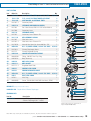
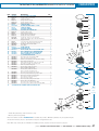
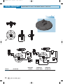
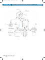
PRODUCT LINE OVERVIEW
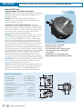
CARBURETORS, REGULATORS & FUELOCKS
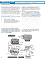
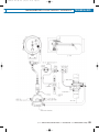
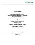
Typical LPG Fuel System (Items highlighted in boldface blue are shown on the diagram)
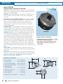
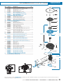
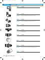
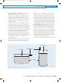
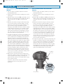
Vacuum Fuelock Filter The Streamline carburetion system
starts with the vacuum fuelock filter (VFF). When a slight
vacuum signal from the engine (2” of water column [W.C].) is
sensed by the VFF, the fuel is allowed to flow through a tenmicron filter to the pressure regulator/vaporizer. When the
vacuum ceases, a spring force pushes on a lever and the
valve operating pin closes against the orifice, thus shutting-off
the fuel flow. Therefore, the vacuum fuelock filter has two
primary functions: (1) it prevents dirty fuel from reaching the
carburetor and (2) it shuts off the fuel flow automatically,
regardless of the ignition being on or off.
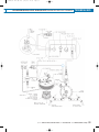
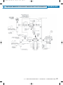
Pressure Regulator/Vaporizer Streamline pressure regulators
are categorized as two-stage, negative pressure,
regulator/vaporizers because they:
1.
Reduce fuel pressure in two stages,
2.
Meter the fuel output in relation to a negative
pressure signal (vacuum) from the carburetors, and
3.
Convert the fuel from a liquid to a vapor.
The negative pressure signal from the carburetor acts upon
the secondary diaphragm, allowing atmospheric pressure from
the upper side to move the diaphragm down. This causes the
secondary seat to open; thus allowing fuel to progress from
the primary chamber of the regulator to the secondary
chamber. To assist in engine start-up, some regulator models
have a primer button. These regulators use engine coolant to
assist in vaporizing the fuel via a heat transfer process that
occurs in the vaporizing chamber.
2
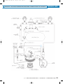
Carburetors The air valve carburetors consist of a mixer,
throttle body and an optional air horn. The air horn enables
the connection of an air hose or air filter assembly. The
throttle valve controls delivery of the air-fuel mixture into the
engine intake manifold based on the operator’s command
(foot pedal).
The air and fuel are mixed at controlled amounts in the
mixer. The air valve spring pushes the air valve assembly
closed until vacuum from the engine causes the spring to
compress and release fuel. The vacuum signal is transmitted
to the air valve assembly via the communication passages on
the air valve assembly. The greater the vacuum draw from
the engine, the more the air valve spring is compressed and
allows a larger amount of fuel to flow and mix with the air.
The air valve spring begins to compress in the presence of 6”
W.C. of vacuum, and the maximum spring displacement will
occur with 24” W.C. of vacuum.
The air-fuel metering device, or mixer, is completely selfcontained. It requires no linkage or idle vacuum line from the
engine intake manifold. This construction allows for great
flexibility in the assembly and service of Streamline
carburetors. The mixer has a replaceable air valve assembly.
Fuel systems using air valve carburetors provide triple safety
seals. When the engine is stopped, fuel cannot pass the air
valve because the air valve spring holds the air valve closed.
At the same time, neither the pressure regulator nor the
vacuum fuelock filter allows the fuel flow as there is no
vacuum signal from the engine.
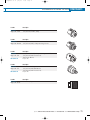
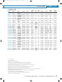
SELECTION CHART
WOODWARD
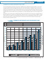
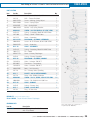
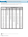
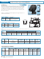
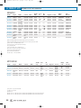
CARBURETOR & REGULATOR SELECTION CHART
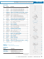
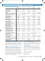
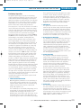
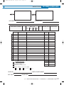
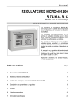
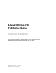
The chart below shows the Streamline carburetors and regulators that are available for specific applications. Simply match
your engine’s flow rate (CFM) and/or horsepower (HP) to the model of carburetor and regulator that best suits your needs.
Carburetor models are listed at the bottom of the chart under each set of vertical bars. Regulators, shown at the top of the
chart, are listed according to fuel type: natural gas (NG), compressed natural gas (CNG) and liquified petroleum gas (LPG).
Regulator models N-LPR, N-PJ, N-51, N-J, and N-S can be used with carburetors shown in the white area (left side of chart).
Regulator models N-H420, N-2001, N-EB, and N-H420 can be used with carburetors shown in the blue area (right side of
chart).
For Example: If an industrial engine has 200 CFM of air flow and runs on CNG, then the recommended carburetor would be
Model N-CA200 and the recommended regulator would be Model N-H420. Or, referencing horsepower, a 300 HP industrial
engine running on LPG would use carburetor Model N-CA-475 and any of the regulator Models N-2001, N-EB, or N-H420.
Note that this chart should be used for reference only. To determine the ideal fuel system components for your engine,
contact a Streamline application engineer.
CARBURETOR AND REGULATOR SELECTION REFERENCE CHART
N-LPR
N-PJ
N-51, N-J, N-S
NG
CNG
LPG
N-H420
N-2001, N-EB, N-H420
400
600
550
350
500
300
450
250
Flow Rate (CFM)
350
200
300
250
150
200
100
150
Maximum Engine Power (HP)
400
100
50
50
0
0
N-CA55
N-CA70
N-CA100
Minimum Flow
N-CA125
N-CA200
Maximum Flow - Industrial
N-CA225
N-CA300
N-CA475
Maximum Flow - Vehicle
phone: 847.967.7730 / 800.451.7040 fax: 815.639.5299 web: www.woodward.com/fsp
3
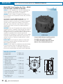
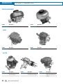
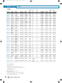
FUEL LOCKOFFS
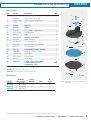
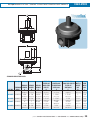
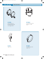
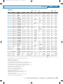
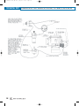
N-VFF30 VACUUM FUELOCK FILTER
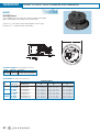
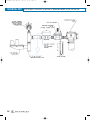
Information & Dimensions
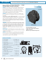
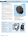
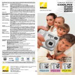
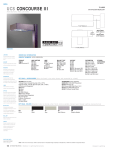
Model N-VFF30 Series Vacuum Fuelock Filter — 325 HP
Parts Description, Installation & Operation
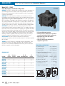
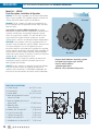
GENERAL The N-VFF30 is a vacuum operated lockoff designed for
low engine vacuum activation. It also contains a filter to remove
foreign materials from the fuel. It is used with high pressure LPG
vapor or liquid withdrawal, where dependable fuel shut-off is
required. It can be used for many mobile powered applications,
such as forklifts, floor buffers or pressure washers.
U.L Listed
WARNING! The N-VFF30 should be installed and maintained per
these instructions and all applicable federal, state, and local laws
and codes.
Special Note in regards to NFPA Pamphlet 58: For indoor applications
by NFPA definition, a regulator is not considered a positive shut-off
valve. An approved automatic shut-off device is required to be
installed. This will shut off the fuel supply should the engine fail
while unattended. Shut-off devices come in vacuum- or solenoidactuated configurations.
OPERATION The N-VFF30 is a dedicated vacuum operated fuelock
designed to shut-off and release fuel. When engine vacuum ceases,
a spring force causes the valve seat to close, shutting off the fuel.
It is important to remember that fuel should not flow to the engine
when it is not in operation. A properly installed N-VFF30 requires
approximately 2 inches of water vacuum to start the opening
sequence.
INSTALLATION The N-VFF30 should be mounted between the fuel
supply and the vaporizer/regulator and be connected to an available
manifold vacuum source.
SERVICE The N-VFF30 should be periodically checked for leakage.
If the unit requires service, we suggest you take it to a qualified
service technician. If not available, Woodward will furnish a list of
repair facilities or provide service information.
FUELOCK SPECIFICATIONS
A. Overall Height . . . . . . . . . . . . 49⁄32" (108.7 mm)
B. Overall Width . . . . . . . . . . . . . 41⁄2" (114.3 mm)
C. Overall Depth . . . . . . . . . . . . . . 23⁄4" (69.9 mm)
D. Front of Fuelock to Center of
Mounting Hole . . . . . . . . . . . . . 15⁄16" (23.8 mm)
E. Mounting Holes Center to Center17⁄8" (47.6 mm)
F. Mounting Hole Diameter . . . . . . . . . . . . . . 1⁄4-20
G. Back of Fuelock to Center of
Fuel Outlet . . . . . . . . . . . . . . . 17⁄16" (36.5 mm)
H. Back of Fuelock to Center of
Vacuum Port . . . . . . . . . . . . . . 11⁄4" (31.6 mm)
J. Air Valve Vacuum Port NPT . . . . . . 1⁄8" (3.2 mm)
K. Fuel Outlet NPT . . . . . . . . . . . . . 1⁄4" (6.35 mm)
L. Fuel Inlet NPT. . . . . . . . . . . . . . . 1⁄4" (6.35 mm)
M. Vent . . . . . . . . . . . . Accepts 1⁄8" (3.2 mm) NPT
4
N-VFF30 Series
•
•
•
•
Fuel lock and filter in one unit
Low (2" W.C.) vacuum signal activation
Liquid or vapor fuel
Rated to 312 psi maximum inlet pressure
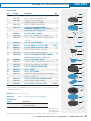
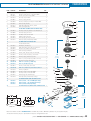
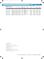
Parts Listing
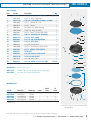
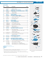
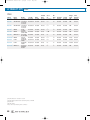
N-VFF30 VACUUM FUELOCK FILTER
FUEL LOCKOFFS
PARTS LISTING
Item
Part No.
Description
Qty.
1*
N00-6443
N-S1-59, Screw, 8-32 x 5⁄8" SEMS
2
N00-4525
N-C1-37, Cover, Diaphragm
1
3*
N00-4723A
N-AD1-26, DIAPHRAGM ASSEMBLY, SILICONE
1
4
N00-6404
N-S1-7, Screw 8-32 x 1/4"
2
5
N00-5016
N-F3-2, Fulcrum
1
6
N00-5654
N-L1-39, Lever, Valve Opening
1
7
N00-4230A
N-AB1-34, Body Assembly
1
8
N00-6402
N-S1-5, Screw, 1/4-20 x 5/8" SEMS
2
9*
N00-7511
N-W1-42, WASHER, SEAL RETAINING
1
10*
N00-6735-1
N-S3-42, SEAL, O-RING
1
11*
N00-5908
N-P1-15, PIN, VALVE OPERATING
1
6 (RK 2)
12*
N00-6806
N-S4-18, SEAT, VALVE
1
13
N00-6623
N-S2-40, Spring, Valve
1
14
N00-6408
N-S1-12, Screw, 8-32 x 5/16" SEMS
1
15*
N00-7003
N-S7-3, SCREEN, FILTER BACKUP
1
16*
N00-4910
FILTER PAD
1
17*
N00-5260
N-G1-89, GASKET, FILTER COVER
1
18*
N00-4910A
FILTER PAD AND GASKET
1
19
N00-4526
N-C1-38, Cover, Filter
1
20*
N00-6478
N-S1-10, SCREW, 12-24 X 3⁄4" SEMS
1
2
3
4
5
6
8
7
10
9
11
12
7 (RK 2)
13
* Indicates Repair Kit Components
14
REPAIR KITS: (Components shown in blue)
N00-6321A
N-RKVFF30-2, Repair Kit with Silicone Diaphragm
N00-4910A
Item 18, Filter Pad and Gasket only
15
16
18
17
ORDERING INFO
Part No.
N00-0124A
N00-0125A
N00-0126A
N00-0128A
N00-0129A
Model No.
N-VFF30-2 *
N-VFF30-2
N-VFF30-2-3
N-VFF30-2-4
N-VFF30-2-5
Diaphragm
Silicone
Silicone
Silicone
Silicone
Silicone
Primer
•
•
Check
Valve
•
•
UL
Listed
•
•
•
•
•
19
20
(*) Blank Cover
Note: Parts in blue are components of Repair Kit
(N-RKVFF30-2).
Note: While only certain parts are available for purchase, all parts are listed for reference purposes.
phone: 847.967.7730 / 800.451.7040 fax: 815.639.5299 web: www.woodward.com/fsp
5
FUEL LOCKOFFS
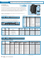
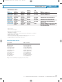
FUEL LOCKS
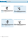
Inline LP-Gas Filter Shut-off Valve,12V
Part No.
Description
N3-0342
1/4" (6.4 mm) NPT Female Inlet,
1/4" (6.4 mm) Male Outlet
Repair Kit
N3-0344-1A
Inline LP-Gas Multi-fuel Shut-off with Magnet
Part No.
Description
N3-0225-4
1/8" (3.2 mm) NPT Female Inlet and
Outlet, Self-Grounded
LP-Gas Multi-fuel Shut-off Solenoid Valve, 12V
Part No.
Description
Part No.
Description
N3-0343
1/4" (6.4 mm) NPT Female Inlet,
1/4" (6.4 mm) Male Outlet
Repair Kit
N3-0173-1
1/4" (6.4 mm) NPT Female Inlet,
1/4" (6.4 mm) Male Outlet
N3-0343-1
6
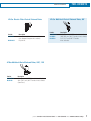
Dual Fuel Gasoline Inline Solenoid, 12V
FUEL LOCKS
LP-Gas Electric Filter Shut-off Solenoid Valve
Part No.
Description
N3-0239
Use with N3-0083-1 Vacuum Switch
(see Control Components section)
Repair Kit
N3-0220-1
FUEL LOCKOFFS
LP-Gas Multi-fuel Shut-off Solenoid Valve, 90°
Part No.
Description
N3-0164-2
N3-0362
N3-0183
1/4" (6.4 mm) NPT Female Inlet & Outlet
3/8" (9.5 mm) NPT Female Inlet & Outlet
1/2" (12.7 mm) NPT Female
Inlet & Outlet
LP-Gas Multi-fuel Shut-off Solenoid Valve, 180°, 12V
Part No.
Description
N3-0165-2
N3-0148
1/4" (6.4 mm) NPT Female Inlet & Outlet
3/4" (19.1 mm) NPT Female Inlet & Outlet
(Low Pres.)
phone: 847.967.7730 / 800.451.7040 fax: 815.639.5299 web: www.woodward.com/fsp
7
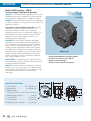
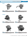
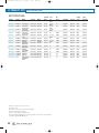
REGULATORS
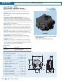
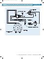
N-LPR VAPOR REGULATOR
Information & Dimensions
Model N-LPR Series Regulator – 25 HP
GENERAL The N-LPR is designed for sensitivity and simple operation.
It is used with low pressure gaseous fuels, where dependable starting is
required. Because of its extreme sensitivity, the N-LPR offers excellent
results in most remote starting applications (standby power generators,
etc.) if installed and maintained properly. Suitable for engines up to
25 HP.
U.L. Listed
WARNING! The N-LPR should be installed and maintained per these
instructions and all applicable federal, state, and local laws and codes.
Special Note in regards to NFPA Pamphlet 58: For indoor applications by
NFPA definition, a regulator is not considered a positive shut-off valve. An
approved automatic shut-off device is required to be installed. This will
shut off the fuel supply should the engine fail while unattended. Shut-off
devices come in vacuum- or solenoid-actuated configurations.
OPERATION The N-LPR is an automatic zero regulator. The engine
creates a vacuum which acts through the outlet of the N-LPR on the
diaphragm. Atmospheric pressure then forces the diaphragm toward the
vacuum, depressing the lever and pulling the valve seat away from the
orifice which allows fuel to flow as long as the demand persists. When
the vacuum ceases, a spring force pushes on the lever and forces the
seat valve against the orifice shutting off the fuel flow. It is important to
remember that fuel should not flow through the N-LPR when the engine is
not running. A properly adjusted N-LPR requires a vacuum of less than
0.35" of water column to start the opening sequence. Due to this
sensitivity, most installations do not need priming to start unless low
cranking speed or restricted and lengthy piping are required.
If priming is necessary and a manual primer is installed, use only
1 or 2 second bursts of fuel and immediately start the engine.
If there is a choke on the carburetor, do not use it as this will probably
cause flooding and hard starting.
INSTALLATION The N-LPR should be mounted as close to the carburetor
as possible with the outlet on top (the arrow on the cover pointing up)
and the diaphragm in a vertical position. This helps to minimize the
effects of gravity on diaphragm travel. The unit should also be placed for
easy access to the primer if provided.
There are two sets of mounting holes provided. Either set of mounts will
adequately support the N-LPR. The bottom set of holes has a 1-3/4"
(44.5 mm) bolt spacing. The mounting bosses on cover are spaced
5-3/4" (146.1 mm) apart for use with 5/16" (7.9 mm) bolts.
Before installing the fuel supply line, be sure that the gas pressure
is no more than the maximum inlet pressure shown on the front of the
N-LPR. If the pressure is greater, leakage could result in a fire hazard
and/or hard starting. The piping to the inlet should be of sufficient size
to allow full fuel flow to the N-LPR. This is very important in natural gas
installations, as any restrictions can affect engine performance.
N-LPR Series
• Sensitive, low pressure vapor regulator with
precise break-off setting
• 11" W.C. (6 oz.) maximum inlet pressure
REGULATOR SPECIFICATIONS
A. Overall Width . . . . . . . . . . . . . . . . . 61⁄4" (158.8 mm)
B. Overall Depth . . . . . . . . . . . . . . . . . 35⁄8" (92.1 mm)
C. Overall Height . . . . . . . . . . . . . . . . 61⁄2" (165.1 mm)
D, E. Mounting Holes
53⁄4"; 13⁄4"
Center to Center . . . . . . . (146.1mm; 44.5 mm)
F. Mounting Holes
Distance from Center . . . . . . . . . . . 121⁄32" (42.1 mm)
G. Air Vent NPT . . . . . . . . . . . . . . . . . . . . 1⁄8" (3.2 mm)
H. Vapor Fuel Inlet NPT . . . . . . . . . . . . . 3⁄4" (19.1 mm)
J. Vapor Fuel Outlet NPT . . . . . . . . . . . . . 3⁄8" (9.5 mm)
K. Test Port NPT . . . . . . . . . . . . . . . . . . . 1⁄8" (3.2 mm)
If a solenoid is used ahead of the N-LPR in the low pressure line,
it should have an orifice at least 7/16" (11.1 mm) in diameter.
Flexible piping to the inlet should be used to prevent cracking from
vibration if the N-LPR is mounted on the engine or other vibrating
surface.
SERVICE The N-LPR should be periodically checked for leakage. If the
unit requires service, we suggest you take it to a qualified service
technician. If not available, Woodward will furnish a list of repair facilities
or provide service information.
K
8
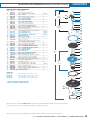
Parts Listing
N-LPR VAPOR REGULATOR
REGULATORS
PARTS LISTING
Item
Part No.
Description
Qty.
1*
N-C11-1
CAP, ADJ. SCREW, TR
1
2
N-S2-18
Screw, Lock, Adj. Spring
1
3
N-S2-11-LPR
Screw, Pressure Adjustment
1
4
N-J1-3
Jet
1
5*
N-W1-6
SEAL, JET
1
6*
N-S3-14
SPRING
1
7
N2-1011
Plug, 1⁄8 NPT, Slotted Head
1
8
N-B1-3-LPR
Standard Body
1
9*
N-S5-1
SEAT
1
10*
N-W1-5-LPR
WASHER, SEAT BACKUP
1
11
N-L1-5A
Lever Assembly
1
12
N-P1-11-LPR
Pin, Lever Fulcrum
1
13
N-S10-11
Screw, #4-40 x 1⁄4" Pan Head
2
14
N-P1-12
Pin, Connector
1
15*
N-D1-7A
DIAPHRAGM ASSEMBLY, SILICONE
1
16
N00-7505
N-W1-27, Washer, Primer
1
17
N-C1-7-LPR
Cover, Back
1
18
N-S2-21-LPR
Spring, Primer
1
19
N-R11-2
Pin, Primer
1
20*
N00-6400
SCREW, 10-24 X 5/8" SLOTTED
FILISTER HEAD WITH SPLIT
LOCKWASHER, SEMS
1
2
3
4
6
5
7
8
9
10
11
12
14
13
15
16
6
(RK4)
17
* Indicates Repair Kit Components
REPAIR KIT:
(Components shown in blue)
N-RK-LPR
Repair Kit with Silicone Diaphragm
18
19
20
ORDERING INFO
Part No.
N-LPR-1A
N-LPR-2A
N-LPR-3A
N-LPR-4A
Maximum
Inlet Pressure
11" WC (6 oz.)
11" WC (6 oz.)
11" WC (6 oz.)
11" WC (6 oz.)
TamperResistant
•
•
Primer
•
•
UL
Listed
•
•
•
•
Note: Parts in blue are components of Repair Kit
(N-RK-LPR).
Note: While only certain parts are available for purchase, all parts are listed for reference purposes.
phone: 847.967.7730 / 800.451.7040 fax: 815.639.5299 web: www.woodward.com/fsp
9
REGULATORS
N-51 VAPOR REGULATOR
Information & Dimensions
Model N-51 – 25 HP
Parts Description, Installation & Operation
U.L Listed*
GENERAL The N-51 is designed for sensitivity and simple operation. It is
used with high pressure propane vapor in applications up to 25 HP.
Because of its compactness, it offers excellent results in most mobile
equipment applications.
WARNING! The N-51 should be installed and maintained per these
instructions and all applicable federal, state, and local laws and codes.
Special Note in regards to NFPA Pamphlet 58: For indoor applications by
NFPA definition, a regulator is not considered a positive shut-off valve.
An approved automatic shut-off device is required to be installed. This
will shut off the fuel supply should the engine fail while unattended.
Shut-off devices come in vacuum- or solenoid-actuated configurations.1
OPERATION LP-gas vapor enters the primary chamber and is then
reduced from the tank pressure to about 4 psi.2 As negative pressure is
transmitted from the carburetor to the regulator, the regulator will allow
fuel to be drawn into the carburetor. Some N-51 models are equipped
with an idle circuit that allows for adjustment of the fuel mixture at low
engine speeds. Some regulators are equipped with a primer button.
Correctly installed regulator should not require priming. If priming is
required, a maximum duration of only 1 second should be used.
INSTALLATION The N-51 should be mounted as close to the
carburetor as possible, with the fuel outlet placed in the lowest position
for best flow.
SERVICE The N-51 should be periodically checked for leakage. If the
unit requires service, we suggest you take it to a qualified service
technician. If not available, Woodward will furnish you a list of repair
facilities or provide service information.
N-51 Series
• LP vapor withdrawal regulator
• Primary pressure setting may be specified
to meet engine displacement requirements
• Adjustable idle circuit with internal
lock off available
• Ideal for indoor mobile maintenance
equipment applications
REGULATOR SPECIFICATIONS
A. Overall Height. . . . . . . . . . 53⁄8" (136.5mm)
B. Overall Depth . . . . . . . . . . . 35⁄8" (92.1mm)
C. Overall Width . . . . . . . . . . 53⁄8" (136.5mm)
D. Back of Regulator to Center of
Vapor Fuel Inlet/Outlet . . . . 15⁄16" (33.3mm)
ORDERING INFO
Part No.
N-51A
N-51A-C
N-51-1A
N-51-1A-C
N-51-2A
N-51-2A-C
N-51-3A
N-51-3A-C
N-51-4A
N-51-4A-C
N-51-5A
N-51-5A-C
N-51-6A
N-51-6A-C
Idle
Circuit
•
•
•
•
•
•
•
•
Vacuum
Lockoff
•
•
•
•
•
•
Primer
•
•
•
•
•
•
•
•
No. Of
Mounting Ears
2
1
2
1
2
1
2
1
2
1
2
1
2
1
UL
Listed*
•
•
•
•
•
•
E. Mounting Holes Center . . . . 4.73"; 1.024"
To Center (2) Locations (120mm; 26mm)
F. Fuel Inlet NPT. . . . . . . . . . . . . 1⁄4" (6.4mm)
G. Vacuum Port NPT . . . . . . . . 1⁄8" (3.2 mm)
H. Primary Test Port NPT . . . . . . 1⁄8" (3.2mm)
J. Vent/Balance Line . . . . . . . . . . . . . . . . N/A
K. Vapor Fuel Outlet NPT . . . . . . 3⁄8" (9.5mm)
C
K
J
10
Parts Listing
N-51 VAPOR REGULATOR
REGULATORS
PARTS LISTING
Item
Part No.
Description
Qty.
1
N-C2-3
Cap, Tamper Resistant
1
2
N-R2-2
Retainer, Spring
1
3*
3B*
N-S2-5
N-S2-5T
4
N-C1-4-1
Cover, Primary
1
5
N-S3-8
Spring, Primary
1
6*
N-G1-3
GASKET, PRIMARY
1
7*
N-D1-6A
DIAPHRAGM ASSEMBLY, PRIMARY
1
8
N-S2-4
Screw, Lever Bridge, 10-32 x 5/16" SLFH
2
9
N-B2-1
Bridge, Primary Lever
1
10
N-P1-5
Pin, Primary Lever
1
11*
N-L1-2
LEVER, PRIMARY
1
12*
N-V1-4
VALVE, SECONDARY SEAT
2
13
N-S3-7
Spring, Primary Lever
1
14
N00-6104
Plug, 1⁄8" NPT, Hex Head
1
15
N00-6402
Screw, 1⁄4-20 x 9/16" SEMS
2
16
N-B1-2A
Body Assembly
1
17
N-S3-9
Spring, Vacuum Lock
1
18*
N-D1-4A
19
N-R3-1
Ring, Vacuum Lock
1
20
N-S2-6
Screw, Vacuum Lock Ring, 10-32 x 3/8"
Slotted Pan Head
4
21
N-S3-12-2
Spring, Secondary Lever
1
22
N-S2-10
Screw, Secondary Lever, 10-32 x 1/4"
Slotted Pan Head
2
SCREW, COVER, 10-32 X 5⁄8" SEMS
SCREW, COVER, 10-32 X 5⁄8" TAMPER RESISTANT
DIAPHRAGM ASSEMBLY, VACUUM LOCK
LEVER ASSEMBLY, SECONDARY
1
3
4
5
6
7
8
9
11
10
12
13
14
15
16
17
18
19
20
21
N-L1-3A
24
N-P1-10
25*
N-D1-5A
DIAPHRAGM ASSEMBLY, SECONDARY
1
26*
N-C2-2
CAP, TAMPER RESISTANT FOR IDLE SCREW
1
27
N-S2-8
Screw, Idle Adjustment (Part of Item 28)
28
N-C1-5A
N-C1-5A-1
N-C1-5A-C
N-C1-5A-1C
Cover
Cover
Cover
Cover
Assembly,
Assembly,
Assembly,
Assembly,
2
6 (RK 4)
4 (RK 2)
23*
Pin, Secondary Lever
1
1
12
1
23
22
24
25
26
28
27
1
Secondary
1
Sec., with Primer
Sec., One Mounting Ear
Sec., w/ Primer, One Mounting Ear
* Indicates Repair Kit Components
REPAIR KIT: (Components shown in blue)
N-RK-51A
3B
Notes:
1. Although some N-51 models are equipped with an internal lockoff to override the idle circuit, this
is not considered a positive shut-off valve per NFPA pamphlet 58.
2. Alternate primary pressure settings are available to meet engine displacement requirements,
ranging from 2.5 psi to 4.5 psi, in 0.5 psi increments. To order primary pressure other than 4.0 psi
add as a suffix to the part number. Ex. N-51A-C-3.0
Note: Parts in blue are components of Repair Kit
(N-RK-51A).
Note: While only certain parts are available for purchase, all parts are listed for reference purposes.
phone: 847.967.7730 / 800.451.7040 fax: 815.639.5299 web: www.woodward.com/fsp
11
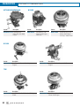
REGULATORS
N-PJ VAPOR REGULATOR
Information & Dimensions
Model N-PJ (CNG) – 100 HP
Parts Description, Installation & Operation
GENERAL The N-PJ type regulator is a two-stage positive
pressure regulator for CNG applications up to 100 HP output.
WARNING! The N-PJ should be installed and maintained per
these instructions and all applicable federal, state, and local
laws and codes.
Special Note in regards to NFPA Pamphlet 58: For indoor
applications by NFPA definition, a regulator is not considered a
positive shut-off valve. An approved automatic shut-off device is
required to be installed. This will shut off the fuel supply should the
engine fail while unattended. Shut-off devices come in vacuum- or
solenoid-actuated configurations.
IMPORTANT NOTE: The N-PJ is rated to 312 psi inlet pressure. In
CNG applications (where tank pressure may exceed 3000 psi) a
separate high-pressure regulator must be installed between the
tank and the N-PJ to reduce the incoming pressure below 312 psi.
OPERATION The low pressure N-JP regulator is a positive pressure
output, two-stage regulator. The unit reduces the compressed
natural gas received from the high pressure regulator to an outlet
pressure slightly above atmospheric pressure.
INSTALLATION The N-PJ should be mounted as close to the
carburetor as possible, with the fuel outlet placed in the lowest
position for best flow.
SERVICE The N-PJ should be periodically checked for leakage.
If the unit requires service, we suggest you take it to a qualified
service technician. If not available, Woodward will furnish a list of
repair facilities or provide service information.
N00-0027A
• Positive pressure regulator for natural gas, CNG
and LP applications
• Rated to 312 psi maximum inlet pressure
ORDERING INFO
Part No.
Description
N00-0027A
N-PJ, CNG Regulator,
Silicone Diaphragm
REGULATOR SPECIFICATIONS
A. Overall Height . . . . . . . . . . . . . 43⁄8" (111.1 mm)
B. Overall Depth . . . . . . . . . . . . . 313⁄16" (96.8 mm)
C. Overall Width. . . . . . . . . . . . . . 45⁄8" (117.5 mm)
D. Back of Regulator to Center of
Vapor Fuel Outlet . . . . . . . . . . . 15⁄8" (41.3 mm)
E. Back of Regulator to Center of
Water Outlet . . . . . . . . . . . . . . . 13⁄8" (34.9 mm)
F. Mounting Holes
Center to Center. . . . . . . . . . . . . 15⁄8" (41.3 mm)
G. Coolant Inlet & Outlet NPT . . . . . . 3⁄8" (9.5 mm)
H. Vapor Fuel Inlet NPT. . . . . . . . . . . 1⁄4" (6.4 mm)
J. Primary Test Port NPT . . . . . . . . . . 1⁄8" (3.2 mm)
K. Vapor Fuel Outlet NPT. . . . . . . . . 1⁄2" (12.7 mm)
L. Vent/Balance Line Connect NPT . . 1⁄8" (3.2 mm)
12
L
Parts Listing
N-PJ VAPOR REGULATOR
REGULATORS
PARTS LISTING
1
Item
Part No.
Description
Qty.
1*
N00-6443
N-S1-59, SCREW, 8-32 X 5⁄8" SEMS
2
N00-6416
N-S1-22, Screw, 6-32 x 1/4" SEMS
4
3
N-C2-4
Cap, Spring Retainer
1
4
N-S2-9
Screw, Spring Retainer
1
3
5
N-N1-1
Nut, Spring Housing
1
4
6
N00-5255
Gasket, Spring Retainer
1
5
7
N00-7004
N-S7-4, Screen, Atmospheric Vent
1
8
N00-4523-2
N-AC1-34-3, Cover Assembly, Secondary
1
6
7
9
N-S3-6
Spring, Positive Pressure
1
8
10*
N00-4733A
N-AD1-26-2, DIAPHRAGM ASSEMBLY, SILICONE
1
11*
N00-6434
N-S1-42, SCREW 8-32 X 3⁄8" SEMS
1
12
N00-5651
N-L1-37, Lever, Secondary Regulator
1
13
N00-5904
N-P1-8, Pin, Secondary Fulcrum
1
14*
N00-6812
N-S4-27, SEAT, SECONDARY REGULATOR
1
15
N00-4229A
N-AB1-33, Body Assembly
1
16
N00-6402
N-S1-5, Screw, 1/4-20 x 5/8" SEMS
2
17
N00-6105
N-P3-14, Plug 1⁄2" NPT
1
18*
N00-6804
N-S4-16, SEAT, PRIMARY REGULATOR
1
19*
N00-5256
N-G1-85, GASKET, BODY TO PLATE
1
20
N00-6009
N-P2-26, Plate, Converter Body Cover
1
21
N00-6104
N-P3-13, Plug, 1⁄8" Pipe, Hex Head
1
22
N00-6711
N-S3-15, Spring, Primary Valve
1
23*
N00-5907
N-P1-14, PIN, PRIMARY VALVE
1
24*
N00-4717A
N-AD1-22, DIAPHRAGM ASSEMBLY, PRIMARY
1
25
N00-4521
N-C1-33, Cover, Primary Regulator
1
26*
N00-6406
N-S1-10, SCREW, 8-32 X 1" SEMS
6 (RK2)
7 (RK2)
2
9
10
11
12
13
14
15
17
16
18
19
* Indicates Repair Kit Components
20
REPAIR KIT: (Components shown in blue)
N00-6315A
N-RK-PJ, Repair Kit with Silicone Diaphragm
22
21
23
24
25
26
Note: Parts in blue are components of Repair Kit
(N-RK-PJ).
Note: While only certain parts are available for purchase, all parts are listed for reference purposes.
phone: 847.967.7730 / 800.451.7040 fax: 815.639.5299 web: www.woodward.com/fsp
13
REGULATORS
N-H420-NG VAPOR REGULATOR
Information & Dimensions
Model N-H420-NG
Parts Description, Installation & Operation
GENERAL The N-H420-NG regulator is designed for use with stationary
engines fueled by natural gas, or in on-highway applications fueled by
compressed natural gas (CNG).
WARNING! The N-H420-NG should be installed and maintained per
these instructions and all applicable federal, state, and local laws
and codes.
Special Note in regards to NFPA Pamphlet 58: For indoor applications
by NFPA definition, a regulator is not considered a positive shut-off
valve. An approved automatic shut-off device is required to be
installed. This will shut off the fuel supply should the engine fail
while unattended. Shut-off devices come in vacuum- or solenoidactuated configurations.
IMPORTANT NOTE: The N-H420-NG is rated to 250 psi inlet pressure.
In CNG applications (where tank pressure may exceed 3000 psi) a
separate high-pressure regulator must be installed between the tank
and the N-H420-NG to reduce the incoming pressure below 250 psi.
OPERATION Natural gas enters the regulator primary chamber and the
pressure of the incoming gas is reduced to approximately 1.5 psi.
The zero governor N-H420-NG will not pass fuel without a vacuum
signal from the carburetor. Its orange secondary spring (N-S3-3)
requires approximately -0.5" of water column to initiate fuel flow.
The positive pressure N-H420-NG works well in venturi applications
where the vacuum signal to the regulator outlet may be weak at low
engine speeds. It will flow fuel at a volumetric rate of approximately
1 CFM with the outlet at atmospheric pressure. Flow is interrupted
when approximately 8 inches of water backpressure is developed at the
outlet.
INSTALLATION The N-H420-NG should be mounted as close to the
carburetor as possible, with the fuel outlet placed in the lowest position
for best flow.
SERVICE The N-H420-NG should be periodically checked for leakage.
If the unit requires service, we suggest you take it to a qualified service
technician. If not available, Woodward will furnish a list of repair
facilities or provide service information.
REGULATOR SPECIFICATIONS
A. Overall Width . . . . . . . . . . . 57⁄10" (144.8 mm)
B. Overall Length . . . . . . . . . . 57⁄10" (144.8 mm)
C. Depth (N-H420-SNGA) . . . . 49⁄10" (124.5 mm)
D. Depth (N-H420-SONGA) . . 49⁄10" (124.5 mm)
E. Mounting Holes
Center to Center. . . . . . . . . . 222⁄25" (73.2 mm)
F. Mounting Screws (4). . . . . . . . . . . . 1⁄4-20 x 5⁄8"
G. Fuel Outlet NPT . . . . . . . . . . . . 1" (25.4 mm)
H. Fuel Inlet NPT . . . . . . . . . . . . . . 1⁄4" 6.4 mm)
J. Coolant Inlet and Outlet NPT . . . 3⁄8" (9.5 mm)
14
N-H420-NG
• Mounts vertically or horizontally
• Positive pressure version flows fuel at 1.0 CFM
with outlet at atmospheric pressure
• Zero governor version with orange secondary
spring initiates fuel flow at -0.5 inches of
water column
Parts Listing N-H420-NG
VAPOR REGULATOR
REGULATORS
PARTS LISTING
Item
Part No.
Description
Qty.
1
N00-6416
Screw – N-S1-22, 6-32 X 1/4" (N-H420-SNGA only)
4
2
N-C2-4
Cap – Spring Retainer (N-H420-SNGA only)
1
3
N-S2-9
Screw – Spring Adjust (N-H420-SNGA only)
1
4
N-N1-1
NUT – Spring Adjust (N-H420-SNGA only)
1
5
N00-6443
SCREW – N-S1-59 COVER, 8-32 X 5/8" SEMS
6
N00-5255
Gasket – N-G1-84, Spring Cap (N-H420-SNGA only) 1
7
N00-7004
Screen – Secondary Vent
1
8
N-C1-1-1
Cover – Secondary (N-H420-SNGA only)
1
N-C1-1
Cover – Secondary (N-H420-SONGA only)
1
9
N-S3-6
Spring – Positive Pressure (N-H420-SNGA only)
1
10*
N-D1-2A
DIAPHRAGM ASSEMBLY, SECONDARY, SILICONE
1
8 (RK 4)
11
N00-6443
Screw – N-S1-59 Cover, 8-32 X 5/8" SEMS
8
12
N-P1-2
Pin – Secondary Lever Fulcrum
1
13
N-L1-1
Lever – Secondary
1
14*
N-V1-1A
VALVE – SECONDARY
1
15
N-S3-3
Spring, Secondary Orange (N-H420-SONGA only)
1
16
N-C1-2
Cover – Primary Diaphragm
1
17
N-S3-4
Spring – Primary Regulator
2
18*
N-D1-3A
DIAPHRAGM ASSEMBLY, PRIMARY
1
19
N00-6104
Fitting – 1/8" NPT Hex Pipe Plug
1
20
N-B1-1CA
Body – Sub-Assembly
1
21
N-P1-3
Pin – Primary Valve Operating
1
22*
N-G1-1
GASKET – GAS & WATER CHAMBER
1
23
N-C1-3
Cover – Gas & Water Chamber
1
24
N-V1-2A
VALVE – PRIMARY
1
25
N-S3-5
Spring – Primary Seat
1
26
N-O1-1
O-RING – LP-GAS INLET
1
27
N-P3-2
Plug – LP-GAS Inlet
1
28*
N00-6400
SCREW – N-S1-3, COVER, 10/24 X 5/8" SEMS
29
N00-6402
Screw – 1/4-20 UNC-2A X 5/8" Hex
12 (RK 2)
4
* Indicates Repair Kit Components
REPAIR KIT:
(Components shown in blue)
N-RKH420SA
Repair Kit with Silicone Diaphragm
ORDERING INFO
Part No.
Description
N-H420-SNGA
Natural Gas Regulator, Adjustable
Positive Pressure
Natural Gas Regulator, Zero Governor
w/ Orange Spring (-0.5" WC)
N-H420-SONGA
Note: Parts in blue are
components of Repair
Kit (N-RKH420SA).
phone: 847.967.7730 / 800.451.7040 fax: 815.639.5299 web: www.woodward.com/fsp
15
REGULATORS
N-J VAPORIZER/REGULATOR
Information & Dimensions
Model N-J – 100 HP
Parts Description, Installation & Operation
GENERAL The N-J type regulator is an LPG liquid withdrawal
high pressure regulator. This regulator provides excellent fuel
delivery with liquid-cooled engines up to 100 HP.
U.L Listed †
WARNING! The N-J should be installed and maintained per
these instructions and all applicable federal, state, and local
laws and codes.
Special Note in regards to NFPA Pamphlet 58: For indoor
applications by NFPA definition, a regulator is not considered
a positive shut-off valve. An approved automatic shut-off
device is required to be installed. This will shut off the fuel
supply should the engine fail while unattended. Shut-off
devices come in vacuum- or solenoid-actuated configurations.
OPERATION Liquid propane enters the regulator and then is
vaporized using heat from the engine’s coolant. Tank pressure
is reduced to approx. 1.5 psi. As negative pressure is
transmitted from the carburetor to the regulator, the regulator
releases propane vapor to the carburetor. Some regulators are
equipped with a primer button. Correctly installed regulator
should not require priming. If priming is required, a maximum
duration of only 1 second should be used.
INSTALLATION The N-J should be mounted as close to the
carburetor as possible, with the fuel outlet placed in the
lowest position for best flow.
SERVICE The N-J should be periodically checked for leakage.
If the unit requires service, we suggest you take it to a
qualified service technician. If not available, Woodward will
furnish a list of repair facilities or provide service information.
N-J Series
• Propane liquid withdrawal vaporizing regulator
• For liquid-cooled engines up to 100 HP
• Ideal for mobile industrial
equipment applications
• Rated to 312 psi maximum inlet pressure
REGULATOR SPECIFICATIONS
A. Overall Height . . . . . . . . . . . . . 43⁄8" (111.1 mm)
B. Overall Depth . . . . . . . . . . . . . . . 3" (76.2 mm)
C. Overall Width. . . . . . . . . . . . . . 45⁄8" (117.5 mm)
D. Back of Regulator to Center of
Vapor Fuel Outlet . . . . . . . . . . . 15⁄8" (41.3 mm)
E. Back of Regulator to Center of
Water Outlet . . . . . . . . . . . . . . . 13⁄8" (34.9 mm)
F. Mounting Holes
Center to Center. . . . . . . . . . . . . 15⁄8" (41.3 mm)
G. Coolant Inlet & Outlet NPT . . . . . . 3⁄8" (9.5 mm)
H. Liquid Fuel Inlet NPT . . . . . . . . . . 1⁄4" (6.4 mm)
J. Primary Test Port NPT . . . . . . . . . . 1⁄8" (3.2 mm)
K. Vapor Fuel Outlet NPT. . . . . . . . . 1⁄2" (12.7 mm)
L. Vent/Balance Line Connect NPT . . 1⁄8" (3.2 mm)
16
L
Parts Listing
N-J VAPORIZER/REGULATOR
REGULATORS
PARTS LISTING
Item
Part No.
Description
Qty.
1*
N00-6443
N-S1-59, SCREW, 8-32 X 5⁄8" SEMS
2
N00-7004
N-S7-4, Screen, Atmospheric Vent
(Part of Item 3)
1
3
N00-4523A
N-AC1-34, Cover Assembly, Secondary:
(N-C1-34, N-S2-21, N-W1-27, N-S7-4)
1
4
N00-7505
N-W1-27, Washer, Hand Primer
(Part of Item 3)
1
5*
N00-4722A
N-AD1-26, DIAPHRAGM ASSEMBLY,
SECONDARY, SILICONE
1
1
1
6 (RK2)
2
3
4
5
6*
N00-6434
N-S1-42, SCREW, 8-32 X 3⁄8" SEMS
7
N00-5651A
N-AL1-37, Lever Assembly, Secondary Regulator 1
6
8
N00-5904
N-P1-8, Pin, Secondary, Fulcrum
1
7
9*
N00-6812
N-S4-27, SEAT, SECONDARY REGULATOR
1
10*
N00-6618**
N-S2-35, SPRING, BLUE SECONDARY
1
8
10
N00-6621**
N-S2-38, SPRING, ORANGE SECONDARY
1
11
N00-4229A
N-AB1-33, Body Assembly
1
12
N00-6402
N-S1-5, Screw 1⁄4-20 x 5/8" SEMS
2
13
N00-6105
N-P3-14, Plug 1/2 NPT
1
14*
N00-6804
N-S4-16, SEAT, PRIMARY REGULATOR
1
15*
N00-5256
N-G1-85, Gasket, Body to Plate
1
13
16
N00-6009
N-P2-26, Plate, Converter Body Cover
1
14
17
N00-6104
N-P3-13, Plug 1⁄8" Pipe, Hex Head
1
18
N00-6711
N-S2-36, Spring, Primary Valve
1
19*
N00-5907
N-P1-14, PIN, PRIMARY VALVE
1
20*
N00-4717A
N-AD1-22, DIAPHRAGM ASSEMBLY, PRIMARY
1
21
N00-4521
N-C1-33, Cover, Primary Regulator
22*
N00-6406
N-S1-10, SCREW, 8-32 X 1" SEMS
* Indicates Repair Kit Components
** Two outlet fuel flow initiation pressures are available. Orange secondary spring (N00-6621)
requires approximately -0.5" of water column to initiate fuel flow. Blue secondary spring
(N00-6618) requires approximately -1.5" of water column.
REPAIR KIT:
12
15
16
17
18
19
20
(Components shown in blue)
N00-6313A
11
1
7 (RK2)
9
21
N-RK-J-2, Repair Kit with Silicone Diaphragm
Blue and Orange Secondary Springs
ORDERING INFO
Part No.
N00-0005A
N00-0009A
N00-0010A
N00-0014A
N00-0024A
N00-0040A
Model No.
N-JB-2
N-JB-2
N-JO-2*
N-JO-2
N-JO-C734
N-JB-L549
Vacuum
H2O
1.5
1.5
1.5
0.5
0.5
1.5
Check
Spring Diaphragm Primer Valve
Blue
Silicone
Silicone
Blue
•
Silicone
Blue
Orange Silicone
Orange Silicone
•
•
Blue
Silicone
•
Inline
UL
Filter Listed†
•
•
•
•
•
•
22
Note: Parts in blue are components of Repair Kit
(N-RK-J-2).
(*) Blank Cover
Note: While only certain parts are available for purchase, all parts are listed for reference purposes.
†
See ordering info chart for U.L. Listed models.
phone: 847.967.7730 / 800.451.7040 fax: 815.639.5299 web: www.woodward.com/fsp
17
REGULATORS
N-2001 VAPORIZER/REGULATOR
Information & Dimensions
N-2001 Vaporizer/Regulator for LPG-fueled engine
–150 HP
GENERAL The N-2001 two-stage regulator is an LPG liquid
withdrawal high-pressure regulator with an integrated heat
exchanger vaporizer. It provides excellent fuel delivery with
liquid-cooled engines up to 150 HP.
UL Listed
WARNING! The N-2001 should be installed and maintained
per these instructions and all applicable federal, state, and
local laws and codes.
Special Note in regards to NFPA Pamphlet 58: For indoor
applications by NFPA definition, a regulator is not considered
a positive shut-off valve. An approved automatic shut-off
device is required to be installed. This will shut off the fuel
supply should the engine fail while unattended. Shut-off
devices come in vacuum- or solenoid-actuated configurations.
OPERATION Liquid propane enters the regulator primary
chamber and is vaporized using heat from the engine’s
coolant. Tank pressure is reduced to approximately 1.5 psi.
As negative pressure is transmitted from the carburetor to the
regulator, the secondary diaphragm depresses the secondary
lever and the regulator releases propane vapor to the
carburetor. The red secondary spring (N-S11-10) requires
approximately -1.0" of water column to initiate fuel flow.
N-2001
• Mounts vertically or horizontally
• Designed for use in closed-loop certified systems
• Propane liquid withdrawal vaporizing regulator
INSTALLATION The N-2001 should be mounted as close to the
carburetor as possible, with the fuel outlet placed in the lowest
position for best flow. If mounted horizontally, the secondary
cover must face up.
• Internally vented (primary diaphragm is
referenced to sedondary chamber pressure)
• For liquid-cooled engines up to 150 HP
SERVICE The N-2001 should be periodically checked for
leakage. If the unit requires service, we suggest you take it to
a qualified service technician. If not available, Woodward will
furnish a list of repair facilities or provide service information.
• Designed for use in closed-loop certified systems
of mobile industrial equipment
• Rated to 312 psi maximum inlet pressure
REGULATOR SPECIFICATIONS
A. Overall Height . . . . . . . . . . 51/5" (132.1 mm)
B. Overall Width . . . . . . . . . . . 44/5" (121.9 mm)
C. Overall Depth . . . . . . . . . . . . 4" (101.6 mm)
B
C
D. Mounting Holes
Center to Center . . . . . . . . . 21/10" (53.3 mm)
E. Fuel Outlet NPT . . . . . . . . . . . 1/2" (12.7 mm)
F. Coolant Inlet and Outlet NPT . . 1/4" (6.4 mm)
G. Fuel Inlet NPT . . . . . . . . . . . . . 1/4" (6.4 mm)
F
A
D
E
G
18
Parts Listing N-2001
VAPORIZER/REGULATOR
REGULATORS
PARTS LISTING
Part
Order No.
Description
Qty.
1*
N00-6443
N-S1-59, COVER SCREW, 8-32 X 5/8" SEMS
2*
1031-1158
T-15, 8-32 X 5/8" TORX TAMPER RESISTANT
2
3*
1012-939
LOCK WASHER, #8 INTERNAL TOOTH
2
4
N-C10-1-1
Secondary Cover
1
5*
N-D10-1A
SECONDARY DIAPHRAGM ASSEMBLY
1
6
N-S10-2
Pan Head Screw, #10-24 x 1/4" w/Star Washer
1
7
N-L10-3
Secondary Lever
1
8*
N-V1-1A
SECONDARY VALVE
1
9
N-P10-1
Secondary Lever Fulcrum Pin
1
10*
N-S11-10
RED SECONDARY SPRING
1
11
N-L10-1
Pilot Valve Lever
1
4 (RK 2)
1
2
3
4
5
7
8
12
N-P10-1-1
Pilot Valve Lever Fulcrum Pin
1
13
N-S10-10
Internal Hex Head Set Screw, #8-32 x 1/4"
1
10
11
12
13
14*
NOO-6413
N-S1-19, COVER SCREW, 12-24 X 5/8" SEMS
6 (RK 2)
14
15
N-C10-3
Primary Diaphragm Cover
1
16
N-S11-1
Primary Regulator Spring
2
17*
N-D1O-2A
PRIMARY DIAPHRAGM ASSEMBLY
1
18
N00-6104
Fitting, 1/8 NPT Hex Pipe Plug
1
16
19
N-B10-1A
Body Assembly
1
17
20*
N-O10-4
BODY SEAL O-RING
1
21*
N-G10-1-1
BODY GASKET
1
22
N-P11-1-1
Regulator Back Plate
1
23*
N-O10-1
PRIMARY SEAL O-RING
1
24*
N-V10-1
PRIMARY REGULATOR VALVE
1
25*
N00-6413
N-S1-19, COVER SCREW, 12-24 X 5/8" SEMS
26*
N-O1-1
INLET SEAL O-RING
1
27
N-P3-2
Inlet Plug
1
28
N00-6402
Screw, 1/4-20 UNC-2A X 5/8" Hex Head, SEMS
2
15
18
19
6 (RK 2)
20
21
* Indicates repair kit components
REPAIR KIT
22
(Components shown in blue)
23
24
25
26
27
N-RK2001-RSA Repair Kit w/ Silicone Diaphragm
ORDERING INFO
Part No.
Description
N-2001-RSA
N-2001 Regulator, Red Spring, w/
Silicone Diaphragm (U.L. Listed)
28
Note: Parts in blue are components of
Repair Kit (N-RK2001-RSA)
Note: While only certain parts are available for purchase, all parts are listed for reference purposes.
phone: 847.967.7730 / 800.451.7040 fax: 815.639.5299 web: www.woodward.com/fsp
19
REGULATORS
N-E VAPORIZER/REGULATOR
Information & Dimensions
Model N-EB-2 Series Regulators For LP-Gas – 400 HP
Parts Description, Installation & Operation
GENERAL The N-E regulator is an LPG liquid withdrawal high
pressure regulator. This regulator provides excellent fuel
delivery with liquid-cooled engines up to 400 HP.
WARNING! The N-E should be installed and maintained per
these instructions and all applicable federal, state, and local
laws and codes.
Special Note in regards to NFPA Pamphlet 58: For indoor
applications by NFPA definition, a regulator is not
considered a positive shut-off valve. An approved automatic
shut-off device is required to be installed. This will shut
off the fuel supply should the engine fail while unattended.
Shut-off devices come in vacuum- or solenoid-actuated
configurations.
OPERATION Inside the N-E regulator, liquid propane enters the
regulator and then is vaporized using heat from the engine's
coolant. Tank pressure is reduced to approximately 1.5 psi.
As negative pressure is transmitted from the carburetor to the
regulator, the regulator releases propane vapor to the
carburetor. N-E regulators are equipped with a primer button.
A correctly installed regulator should not require priming. If
priming is required, a maximum duration of only 1 second
should be used.
INSTALLATION The N-E should be mounted as close to the
carburetor as possible, with the fuel outlet placed in the
lowest position for best flow.
SERVICE The N-E should be periodically checked for leakage.
If the unit requires service, we suggest you take it to a
qualified service technician. If not available, Woodward will
furnish a list of repair facilities or provide service information.
REGULATOR SPECIFICATIONS
A. Overall Height . . . . . . . . . . . . 71⁄4" (184.2 mm)
B. Overall Depth . . . . . . . . . . . . . 4" (101.6 mm)
C. Back of Converter to Center
of Vapor Fuel Outlet . . . . . . . . . 2" (50.8 mm)
D. Back of Converter to Center
of Water Outlet . . . . . . . . . . . . . 1" (25.4 mm)
E. Mounting Holes,
Center-to-Center . . . . . . . . . . 65⁄8" (168.3 mm)
F. Mounting Hole Diameter . . . . . . 9⁄32" (7.1 mm)
G. Coolant Inlet & Outlet NPT . . . . . 3⁄8" (9.5 mm)
H. LPG Fuel Inlet NPT . . . . . . . . . . 1⁄4" (6.4 mm)
J. Secondary Accessory Port NPT. . 1⁄8" (3.2 mm)
K. Primary Test Port NPT . . . . . . . . 1⁄8" (3.2 mm)
L. Vapor Fuel Outlet NPT . . . . . . . 1" (25.4 mm)
M. Vent/Balance Line
Connection NPT . . . . . . . . . . . . 1⁄8" (3.2 mm)
20
N-EB-2 Series
• Propane liquid withdrawal vaporizing regulator
• For liquid-cooled engines up to 400 HP
• -1.5" W.C. fuel initiation (break-off) pressure
• Rated to 312 psi maximum inlet pressure
Parts Listing
N-E VAPORIZER/REGULATOR
REGULATORS
PARTS LISTING
Qty.
1
8 (RK3)
2
Item
Part No.
Description
1*
N00-6400
N-S1-3, SCREW, 10-24 X 5⁄8" SEMS
2
N00-7002
N-S7-1, Screen, Atmospheric Vent
1
3
N00-4509
N-ACI-22-1, Cover Assembly,
Secondary: with Primer Button
1
4
N00-7505
N-W1-27, Washer, Hand Primer
1
5*
N00-4718A
N-AD1-23, DIAPHRAGM ASSEMBLY,
SECONDARY, SILICONE: N-D1-23, N-P22-14,
N-P2-14 (2), N-L2-1, N-R2-3 (2)
1
3
4
5
6
6*
N00-5681
N-L1-86A, LEVER, SILICONE
1
7
N00-5903
N-P1-7, Pin, Secondary Lever Fulcrum
1
8
N00-6610**
N-S2-22, Spring, Secondary Regulator, (Blue)
1
-1.5" W.C.
1
7
8
9
10
9*
N00-6820
N-S4-37, SEAT, SECONDARY
10*
N00-6431
N-S1-39, SCREW, 12-24 X 7⁄8" SEMS
7 (RK2)
11*
N00-6432
N-S1-40, SCREW, 10-24 X 3⁄8" SEMS
2
12
N00-4506
N-C1-20, Cover, Primary Diaphragm
1
13
N00-6604
N-S2-13, Spring, Primary Regulator
2
14*
N00-4709A
N-AD1-15, DIAPHRAGM ASSEMBLY, PRIMARY:
1
13
14
11
12
N-D1-15, N-P2-16, N-P2-17, N-R2-3 (3)
15*
N00-5906
N-P1-11, PIN, PRIMARY VALVE
2
16
N00-4216
N-AB1-20, Body, Regulator: N-B1-20, N-J1-13
1
17
N00-6104
N-P3-13, Plug, 1⁄8" Pipe, Hex Head
2
15
18*
N00-5225
N-G1-37, GASKET, REGULATOR BODY
1
16
19*
N00-5015
N-F3-1, SPONGE
1
20*
N00-6801
N-S4-7, SEAT, PRIMARY
1
21
N00-4212
N-AB1-19-1, Body Assembly, Heat Exchanger:
1
18
N-B1-19-1, N-J1-9
22*
N00-5224
N-G1-35, GASKET, HEAT EXCHANGER COVER
1
23
N00-4507
N-C1-21, Cover, Heat Exchanger
1
24*
N00-6400
N-S1-3 SCREW, 10-24 X 5⁄8" SEMS
19
6 (RK3)
* Indicates Repair Kit Components
** Blue secondary spring (N00-6610) requires approximately negative 1.5 inches of water outlet fuel
flow initiation pressure.
REPAIR KIT:
17
20
21
17
(Components shown in blue)
N00-6301A
N-RK-E-2, Repair Kit with Silicone Diaphragm
22
ORDERING INFO
Part No.
Description
N00-0001A
N-EB-2 Regulator w/
Silicone Diaphragm
23
24
Note: Parts in blue
are components of
Repair Kit (N-RK-E-2).
Note: While only certain parts are available for purchase, all parts are listed for reference purposes.
phone: 847.967.7730 / 800.451.7040 fax: 815.639.5299 web: www.woodward.com/fsp
21
REGULATORS
N-H420 VAPORIZER/REGULATOR
Information & Dimensions
Model N-H420 Regulator – 400 HP
Parts Description, Installation & Operation
GENERAL The N-H420 two-stage regulator is an LPG liquid
withdrawal high pressure regulator with a heat exchanger
that will vaporize enough fuel for up to 400 HP engines.
U.L Listed
WARNING! The N-H420 should be installed and maintained
per these instructions and all applicable federal, state, and
local laws and codes.
Special Note in regards to NFPA Pamphlet 58: For indoor
applications by NFPA definition, a regulator is not
considered a positive shut-off valve. An approved
automatic shut-off device is required to be installed. This
will shut off the fuel supply should the engine fail while
unattended. Shut-off devices come in vacuum- or
solenoid-actuated configurations.
OPERATION With the N-H420's improved vaporization
characteristics, liquid propane enters the regulator and
then is vaporized using heat from the engine's coolant.
Tank pressure is reduced to approximately 1.5 psi. As
negative pressure is transmitted from the carburetor to
the regulator, the regulator releases propane vapor to the
carburetor. Some regulators are equipped with a primer
button. Correctly installed regulator should not require
priming. If priming is required, a maximum duration of
only 1 second should be used.
INSTALLATION The N-H420 should be mounted as close
to the carburetor as possible, with the fuel outlet placed in
the lowest position for best flow.
SERVICE The N-H420 should be periodically checked for
leakage. If the unit requires service, we suggest you take
it to a qualified service technician. If not available, we will
furnish a list of repair facilities or provide service
information.
REGULATOR SPECIFICATIONS
A. Overall Width . . . . . . . . . . . 511⁄16" (144.5 mm)
B. Overall Depth . . . . . . . . . . . 41⁄8" (104.8 mm)
C. Mounting Holes
Center to Center 27⁄8" x 27⁄8" (73 mm x 73 mm)
D. Mounting Hole Diameter . . . . . . . . . 1⁄4"-20 (4)
E. Fuel Inlet NPT . . . . . . . . . . . . . . 1⁄4" (6.4 mm)
F. Fuel Outlet NPT . . . . . . . . . . . . 1" (25.4 mm)
G. Coolant Inlet and Outlet NPT . . . 3⁄8" (9.5 mm)
22
N-H420 Series
•
•
•
•
Propane liquid withdrawal vaporizing regulator
For liquid-cooled engines up to 400 HP
Compact, low-profile design
Rated to 312 psi maximum inlet pressure
Parts Listing
N-H420 VAPORIZER/REGULATOR
REGULATORS
PARTS LISTING
Item
Part No.
Description
Qty.
1*
N00-6443
COVER SCREW, 8-32 X 5⁄8"
2
N00-7004
Screen, Secondary
1
3
N-C1-1A
Cover Assembly, Secondary
1
4*
N-D1-2A
DIAPHRAGM ASSEMBLY, SECONDARY, SILICONE
1
5
N00-6443
Cover Screw, 8-32 x 5/8"
8
6
N-P1-2
Pin, Secondary Lever Fulcrum
1
7
N-L1-1
Lever, Secondary
1
8*
N-V1-1A
VALVE, SECONDARY
1
9
N-S3-2
Spring, Secondary (Blue)**
1
10
N-S3-3
Spring, Secondary (Orange)**
1
11
N-C1-2
Cover, Primary Diaphragm
1
12
N-S3-4
Spring, Primary Regulator
2
13*
N-D1-3A
DIAPHRAGM ASSEMBLY, PRIMARY
1
14
N-B1-1A
Body Assembly
1
15
N00-6104
Plug, 1⁄8" Pipe
1
16
N-P1-3
Pin, Primary Valve Operating
1
17*
N-G1-1
GASKET, GAS & WATER CHAMBER
1
18
N-C1-3
Cover, Gas & Water Chamber
1
19*
N00-6400
COVER SCREW, 10-24 X 5⁄8"
20
N00-6402
Mounting Screw, 1⁄4"-20 x 5/8"
4
21*
N-V1-2A
VALVE, PRIMARY REGULATOR
1
22
N-S3-5
Spring, Valve Closing
1
23*
N-O1-1
O-RING, LP-GAS INLET
1
24
N-P3-2
Plug, LP-Gas Inlet
1
8 (RK4)
1
2
3
4
5
7
6
8
9,10
11
12
12 (RK2)
13
15
14
* Indicates Repair Kit Components
** Two outlet fuel flow initiation pressures are available. Orange secondary spring (N-S3-3) requires
approximately negative 0.5 inches of water pressure to initiate fuel flow. Blue secondary spring
(N-S3-2) requires approximately negative 1.5 inches of water pressure.
16
17
REPAIR KIT:
(Components shown in blue)
N-RKH420SA
Repair Kit with Silicone Diaphragm
18
ORDERING INFO
Part No.
Description
N-H420-SA
N-H420 Regulator, Blue Spring with
Silicone Diaphragm (UL Listed)
N-H420-OSA
N-H420 Regulator, Orange Spring with
Silicone Diaphragm (UL Listed)
19
20
21
Note: Parts in blue are
components of Repair Kit
(N-RKH420SA).
22
23
24
Note: While only certain parts are available for individual purchase, all parts are listed for reference purposes.
phone: 847.967.7730 / 800.451.7040 fax: 815.639.5299 web: www.woodward.com/fsp
23
REGULATORS
N-H420 TURBO VAPORIZER/REGULATOR
Information & Dimensions
Model N-H420 Turbo
Parts Description, Installation & Operation
GENERAL The N-H420 Turbo two-stage regulator is an LPG liquid
withdrawal high-pressure regulator with an integrated heat
exchanger vaporizer.
WARNING! The N-H420 Turbo should be installed and
maintained per these instructions and all applicable federal,
state, and local laws and codes.
Special Note in regards to NFPA Pamphlet 58: For indoor
applications by NFPA definition, a regulator is not considered a
positive shut-off valve. An approved automatic shut-off device is
required to be installed. This will shut off the fuel supply should
the engine fail while unattended. Shut-off devices come in
vacuum- or solenoid-actuated configurations.
OPERATION Liquid propane enters the regulator primary chamber
and is vaporized using heat from the engine’s coolant. Tank
pressure is reduced to 38-54 inches of water — approximately
1.5 psi. The idle outlet pressure is pre-set to positive 0.4 ± 0.1
inch of water at 1.0 CFM with no boost applied. Turbo boost
pressure up to 15 psi may be applied at the hose barb fitting on
the cover to maintain the 0.4 ± 0.1 inch of water pressure
differential across the secondary diaphragm during turbocharging.
The primary diaphragm is referenced to the secondary chamber,
so primary pressure is always equal to outlet pressure plus 38-54
inches of water. Schrader valves mounted in the primary and
secondary chambers and a thermocouple transducer (for
sensing secondary gas temperature) allow for quick diagnostics,
and may be used in the fuel system closed-loop control strategy.
N-H420 Turbo
• Mounts vertically or horizontally
• Boost pressure up to 15 psi
• Pre-set positive 0.4 ± 0.1 inches of water
idle outlet pressure at 1.0 CFM (with no
boost applied)
• Designed for use in closed-loop systems
• Built to withstand extreme vibration conditions
INSTALLATION The N-H420 Turbo should be mounted as close to
the carburetor mixer/venturi as possible, with the fuel outlet
placed in the lowest position for best flow.
SERVICE The N-H420 Turbo should be periodically checked for
leakage. If the unit requires service, we suggest you take it to a
qualified service technician. If not available, Woodward will
furnish a list of repair facilities or provide service information.
REGULATOR SPECIFICATIONS
A
A. Overall Width . . . . . . . . . . . . . . 61⁄2" (165.1 mm)
B. Overall Length . . . . . . . . . . . . 61⁄10" (154.9 mm)
C. Body Width. . . . . . . . . . . . . . . 57⁄10" (144.8 mm)
F
B
D. Overall Depth . . . . . . . . . . . . . 53⁄5" (142.2 mm)
E. Mounting Holes Center to Center222⁄25" (73.2 mm)
F. Mounting Screws (4). . . . . . . . . . . . . . 1⁄4-20 x 5⁄8"
E
G
C
J
K
G. Fuel Outlet NPT. . . . . . . . . . . . . . 1" (25.4 mm)
H. Fuel Inlet NPT. . . . . . . . . . . . . . . . 1⁄4" (6.4 mm)
D
E
J. Coolant Inlet and Outlet NPT . . . . . 3⁄8" (9.5 mm)
K. Hose Barb . . . . . . . . . . . . . . . . . . . ⁄8" (9.5 mm)
3
H
24
Parts Listing N-H420
TURBO VAPORIZER/REGULATOR
REGULATORS
PARTS LISTING
Item
Part No.
Description
Qty.
1
1036-611
Screw – Socket Head Cap #6
4
2
N-C2-3
CAP – Tamper-Resistant
1
3
3381-1010
Screw – Locking, Spring Adjust
1
4
5352-1000
Screw – Spring Adjust
1
5
4250-1051
Cap – Spring Adjust
1
6
N00-5255-P
Gasket – Cap Spring Retainer
1
7*
N00-6443
SCREW – N-S1-59 COVER, 8-32 X 5/8" SEMS
8
8
N-S3-2-P
Spring – Secondary, Model N-H420 Turbo
1
9
N2-1039
Fitting – 1/8 NPT X 3/8" Hose
1
10
N-C1-1-1
Cover – Secondary
1
11*
6612-1010
DIAPHRAGM – ASSEMBLY, SECONDARY
1
12
N00-6443
Screw – N-S1-59 cover, 8-32 X 5/8" SEMS
8
13
5300-1015
Lever – Secondary
1
14*
N-V1-1A
VALVE – SECONDARY
1
15
N-S3-2-P
Spring - Secondary, Model N-H420 Turbo
1
16
1002-727
Pin – Dowel
1
17
3550-1173
Cover – Primary Diaphragm
1
18
N-S3-4
Spring – Primary Regulator
2
19*
N-D1-3A
DIAPHRAGM – ASSEMBLY, PRIMARY
1
20
1310-913
Valve – Schrader 1/8" NPT
1
21
6913-007
Transducer – Temperature
1
22
1310-913
Valve – Schrader 1/8" NPT
1
23
4030-1056
Body – Sub-Assembly
1
24
N-P1-3
Pin – Primary Valve Operating
1
25*
N-G1-1
GASKET – GAS & WATER CHAMBER
1
26
N-C1-3
Cover – Gas & Water Chamber
1
27*
N00-6400
SCREW – N-S1-3, COVER, 10/24 X 5/8" SEMS
28
N00-6402
Screw – 1/4-20 UNC-2A X 5/8" Hex
4
29*
N-V1-2A
VALVE – PRIMARY
1
30
N-S3-5
Spring – Primary Seat
1
31*
N-O1-1
O-RING – LP-GAS INLET
1
32
N-P3-2
Plug – LP-Gas Inlet
12
* Indicates Repair Kit Components
REPAIR KIT:
(Components shown in blue)
5233-1005-RK Repair Kit with Silicone Diaphragm
ORDERING INFO
Note: Parts in blue are components of
Repair Kit (5233-1005-RK).
Part No.
Description
5233-1005
N-H420 Regulator, Positive Pressure,
with 15 psi Boost
phone: 847.967.7730 / 800.451.7040 fax: 815.639.5299 web: www.woodward.com/fsp
25
REGULATORS
N-S VAPORIZER/REGULATOR
Information & Dimensions
Model N-S Regulator – 100 HP
Parts Description, Installation & Operation
GENERAL The N-S type regulator is an LPG liquid
withdrawal two-stage vaporizer/regulator. This regulator
provides excellent fuel delivery with liquid-cooled engines
up to 100 HP.
WARNING! The N-S should be installed and maintained
per these instructions and all applicable federal, state, and
local laws and codes.
Special Note in regards to NFPA Pamphlet 58: For indoor
applications by NFPA definition, a regulator is not
considered a positive shut-off valve. An approved automatic
shut-off device is required to be installed. This will shut off
the fuel supply should the engine fail while unattended.
Shut-off devices come in vacuum- or solenoid-actuated
configurations.
OPERATION Liquid propane enters the regulator and then
is vaporized using heat from the engine's coolant. Tank
pressure is reduced to approximately 1.5 psi. As negative
pressure is transmitted from the carburetor to the regulator,
the regulator releases propane vapor to the carburetor.
INSTALLATION The N-S should be mounted as close to the
carburetor as possible, with the fuel outlet placed in the
lowest position for best flow.
SERVICE The N-S should be periodically checked for
leakage. If the unit requires service, we suggest you take
it to a qualified service technician. If not available,
Woodward will furnish a list of repair facilities or provide
service information.
N-S Series
• Propane liquid withdrawal vaporizing regulator
• For liquid-cooled engines up to 100 HP
• New primary seat design
• Improved safety characteristics
• Ideal for mobile industrial equipment applications
• Rated to 312 psi maximum inlet pressure
REGULATOR SPECIFICATIONS
A. Overall Height . . . . . . . . . . . . . 43⁄8" (111.1 mm)
B. Overall Depth . . . . . . . . . . . . . . . 3" (76.2 mm)
C. Overall Width. . . . . . . . . . . . . . 45⁄8" (117.5 mm)
D. Back of Regulator to Center of
Vapor Fuel Outlet . . . . . . . . . . . 15⁄8" (41.3 mm)
E. Back of Regulator to Center of
Water Outlet . . . . . . . . . . . . . . . 13⁄8" (34.9 mm)
F. Mounting Holes
Center to Center. . . . . . . . . . . . . 15⁄8" (41.3 mm)
G. Coolant Inlet & Outlet NPT . . . . . . 3⁄8" (9.5 mm)
H. Liquid Fuel Inlet NPT . . . . . . . . . . 1⁄4" (6.4 mm)
J. Primary Test Port NPT . . . . . . . . . . 1⁄8" (3.2 mm)
K. Vapor Fuel Outlet NPT. . . . . . . . . 1⁄2" (12.7 mm)
L. Vent/Balance Line Connect NPT . 1⁄8" (13.2 mm)
26
L
Parts Listing
N-S VAPORIZER/REGULATOR
REGULATORS
PARTS LISTING
Item
Part No.
Description
Qty.
1*
N00-6443
N-S1-59, SCREW, 8-32 X 5⁄8" SEMS
2
N00-7004
N-S7-4, Screen, Atmospheric Vent
1
3
N00-4523-1
Cover Assembly, Secondary
1
4*
N00-4722A
N-AD1-26, DIAPHRAGM ASSEMBLY,
SECONDARY, SILICONE
1
5*
N00-6434
N-S1-42, SCREW 8-32 X 3⁄8" SEMS
1
6
N00-5651
N-L1-37, Lever Assembly, Secondary Regulator
1
7
N00-5904
N-P1-8, Pin, Secondary Fulcrum
1
8*
N00-6812
N-S4-27, SEAT, SECONDARY REGULATOR
1
9
N00-6618**
N-S2-35, Spring, Blue Secondary (N-SBA)
1
N00-6621**
N-S2-38, Spring, Orange Secondary (N-SOA)
N00-4229A
N-AB1-33, Body Assembly
10
N00-6402
N-S1-5, Screw, 1/4-20 x 5/8" SEMS
2
N00-6105
N-P3-14, Plug, Pipe
1
13*
N00-6804-1
N-S4-16-2, SEAT, PRIMARY REGULATOR
1
14*
N00-5256
N-G1-85, GASKET, BODY TO PLATE
1
15
N00-6009
N-P2-26, Plate, Converter Body Cover
1
16
N00-6104
N-P3-13, Plug, 1⁄8" Pipe, Hex Head
1
17
N00-6711
N-S3-15, Spring, Primary Valve
1
18*
N-P10-3
PIN, PRIMARY VALVE
1
19*
N00-4717-1A
N-AD1-22-1, DIAPHRAGM ASSEMBLY, PRIMARY
1
N-C1-33, Cover, Primary Regulator
21*
N00-6406
N-S1-10, SCREW, 8-32 X 1" SEMS
3
4
1
12
N00-4521
2
5
11
20
1
6 (RK2)
1
7
6
8
9
10
12
11
13
14
7 (RK2)
* Indicates Repair Kit Components
** Two outlet fuel flow initiation pressures are available. Orange secondary spring (N00-6621)
requires approximately -0.5" of water pressure to initiate fuel flow. Blue secondary spring
(N00-6618) requires approximately -1.5" of water pressure.
15
17
REPAIR KIT: (Components shown in blue)
N-RK-S-2A
16
18
Repair Kit with Silicone Diaphragm
19
20
ORDERING INFO
Part No.
Description
N-SBA
N-S, Regulator, with Silicone
Diaphragm, Blue Spring (-1.5")
N-SOA
N-S, Regulator, with Silicone
Diaphragm, Orange Spring (-0.5")
21
Note: Parts in blue are components of Repair Kit
(N-RK-S-2A).
Note: While only certain parts are available for individual purchases, all parts are listed for reference purposes.
phone: 847.967.7730 / 800.451.7040 fax: 815.639.5299 web: www.woodward.com/fsp
27
REGULATORS
MODEL N-L VAPORIZER/REGULATOR REPAIR KIT Parts Listing
Repair Kit only for Model L Regulators
While Woodward does not manufacture Model L regulators,
we do provide repair kits for them. Components of these
kits are shown in blue on the parts diagram.
1
2
3
REPAIR KIT COMPONENTS
4
Item
Part No.
Description
1
N00-6443
N-S1-9, Screw, 8-32 x 5/8" SEMS
3
5
N00-4725A
N-AD1-23, Diaphragm Assembly,
Secondary, Hydrin
1
N00-4726A
Qty.
5
6
N-AD1-23, Diaphragm Assembly,
Secondary, Silicone
7
8
N00-6820
N-S4-37, Seat, Secondary
1
13
N00-4731A
N-AD1-32, Diaphragm Assembly, Primary
1
16
N00-5275
N-G1-118, Gasket, Water Passage
1
21
N00-5276
N-G1-119, Gasket, Vaporization Chamber
1
23
N00-6400
N-S1-3, Screw, 10-24 x 5/8" SEMS
3
24
N00-6806
N-S4-18, Seat, Primary Valve
1
25
N00-6808A
N-S4-23, Seat, Support, Primary
1
9
8
11
10
12
14
13
18
15
16
17
19
ORDERING INFO
Part No.
Description
N00-6316A
N-RK-L, Repair Kit with Hydrin Diaphragm
N00-6317A
N-RK-L-2, Repair Kit with Silicone Diaphragm
20
21
22
23
24
25
26
27
Note: Parts in blue are components of
Model L Repair Kits.
28
Gas Vapor MODEL
N-IMP SERIES PRESSURE REDUCTION VALVES
REGULATORS
STANDARD REDUCTION VALVES
OVERALL OVERALL OVERALL
STANDARD LENGTH WIDTH
HEIGHT
PART NO.
VALVE
A
B
C
3-1/4"
5-1/16"
N00-0054 N-IMP52 3-3/16"
(80.96mm) (82.55mm) (128.59mm)
N00-0055 N-IMP53
3-5/8"
3-7/8"
5-9/16"
(92.08mm) (98.43mm) (141.29mm)
N00-0056 N-IMP61
4-3/8"
5-7/16"
6-7/16"
(111.13mm)(138.11mm) (163.51mm)
N00-0057 N-IMP81
6"
7"
8-3/8"
(152.4mm) (177.8mm) (212.73mm)
N00-0058 N-IMP91
7-1/8"
9-1/8"
10-1/2"
(180.98mm) (231.78mm) (266.7mm)
BOTTOM TO
CENTER OF
VAPOR FUEL
OUTLET
D
1-1/2"
CENTER OF
CENTERLINE VAPOR FUEL OUTLET INLET &
TO CENTER OF
TO TOP OF
OUTLET
VENT BOSS
VENT BOSS
NPT
E
F
G
1-3/32"
2"
3/4"
VENT
BOSS
DIA.
I
1/8"
(38.1mm)
(27.78mm)
(50/8mm)
(19.1mm)
1-11/32"
1-15/32"
2-11/32"
1"
(3.2mm)
1/8"
(34.13mm)
(37.31mm)
(59.53mm)
(25.4mm)
(3.2mm)
1-21/32"
1-27/32"
2-7/8"
1-1/4"
1/8"
(42.07mm)
(46.83mm)
(73.03mm)
(31.75mm)
(3.2mm)
2-1/32"
2-3/8"
3-1/16"
1-1/2"
1/8"
(51.59mm)
(60.36mm)
(77.79mm)
(38.1mm)
(3.2mm)
2-7/16"
3-1/4"
4-3/16"
2"
1/8"
(64.45mm)
(82.55mm)
(106.36mm)
(50.8mm)
(3.2mm)
phone: 847.967.7730 / 800.451.7040 fax: 815.639.5299 web: www.woodward.com/fsp
29
REGULATORS
PRESSURE REDUCTION VALVES FLOW CAPACITY
Cubic Feet per Hour (CFH)
This chart shows pressure drop values for each model with the regulator in the open position. Differential
pressure (inlet pressure minus outlet pressure) must be at least twice pressure drop value for practical use.
Maximum recommended capacity limit is at a flow equivalent to 4.0" W.C. pressure drop.
PRESSURE DROP MODEL/PIPE SIZE
RATE OF FLOW
CFH 0.64 GR GAS
100
200
300
400
500
600
700
800
900
1,000
1,100
1,200
1,300
1,400
1,500
1,600
1,700
1,800
1,900
2,000
2,500
3,000
3,500
4,000
4,500
5,000
5,500
6,000
6,500
7,000
7,500
8,000
8,500
9,000
!
30
N-IMP52
3/4" (19.1mm)
.18
.39
.70
1.10
1.58
2.16
2.82
3.55
4.37
5.30
N-IMP53
N-IMP60
N-IMP81
1" (25.4mm) 1-1/4" (31.75mm) 1-1/12" (38.1mm)
.13
.24
.37
.54
.73
.95
1.20
1.48
1.79
2.13
2.52
2.90
3.31
3.78
4.27
4.80
.16
.23
.32
.41
.52
.64
.78
.93
1.09
1.26
1.45
1.65
1.87
2.09
2.33
2.58
4.03
5.80
7.90
.13
.16
.20
.24
.28
.33
.38
.44
.50
.56
.63
.71
.78
1.22
1.76
2.38
3.12
3.95
4.86
5.90
WARNING: Improper installation or use of this product may cause serious injury and/or property damage.
N-IMP91
2" (50.8mm)
.12
.14
.15
.18
.20
.22
.25
.27
.43
.62
.84
1.09
1.39
1.71
2.07
2.46
2.90
3.35
3.85
4.39
4.95
CARBURETORS
phone: 847.967.7730 / 800.451.7040 fax: 815.639.5299 web: www.woodward.com/fsp
31
CARBURETORS
MODEL N-CA55-500 SERIES
For LP and Natural Gas
N-CA55-500 Series
For LP-Gas & Natural Gas
Mixer
Carburetors consist of a mixer, throttle body assembly, and an optional air horn.
The mixer has a replaceable air valve assembly. The charts below describe these
components and the most common combinations available as CA55-500 Series
carburetors. Other combinations of air valve assemblies and air horns can be built
for your specific requirements. (Minimum quantities may be required.)
Throttle
Body
Assembly
Letters in ( ) refer to the dimension diagrams on facing page. Numbers in ( )
indicate metric dimensions.
AIR VALVE ASSEMBLY (Item No. 8 on Parts List)
Part No.
N00-7462A
Model No.
N-AV1-18
AIR HORN (Item No. 2 on Parts List)
Description
Standard air valve assembly
Part No.
N1-4063
N1-4064
N1-4065
N1-4066
N00-4067
N00-4068
N00-4070
N00-4070-1
N1-4086
MIXERS (Item No. 13 on Parts List) The chart below lists the
most common mixer assemblies. Please contact factory for other
assemblies that can be built to your specific requirements.
AIR HORN
DIAMETER
N/A
Fuel Inlet
NPT
(E)
Standard Air Valve
Mixer Part No.
Mixer Model No.
N00-0405A
N-CA55M-500
Model No.
N-A2-35
N-A2-36
N-A2-37
N-A2-38
N-A2-39
N-A2-39-1
N-A2-41
N-A2-41
A2-65
3/8" (9.5mm)
N1-4085
N1-4085-1
N1-4081
A2-61
A2-61-2
A2-59
Description
Aluminum
Aluminum
Aluminum
Aluminum
Aluminum
Polycarbonate
Polycarbonate
Aluminum
Adapter for
Toyota 4Y engines
8mm center stud
8mm center stud
Aluminum
Diameter (C)
1-1/2" (38.1mm)
1-5/8" (41.40mm)
1-7/8" (47.75mm)
2-1/16" (52.32mm)
2-1/16" (52.32mm)
2-5/16" (58.67mm)
2-5/16" (58.67mm)
N/A
2-1/2" (63.5mm)
2-1/2" (63.5mm)
1-11/16" (42.80mm)
THROTTLE BODY ASSEMBLIES (Item No. 20 on Parts List)
Part No.
N1-7251
N1-7253
N00-7255
N1-7256
N00-7259
N1-7260
N00-4096*
Model No.
N-AT2-24
N-AT2-25
N-AT2-26
N AT2-26-2
N-AT2-27
N-AT2-27-2
N-A2-41
Center to Center
Bolt Spacing
(A)
Flange
1/2" SAE (12.7mm)
3/4" SAE (19.05mm)
1" SAE (25.4mm)
1" SAE (25.4mm)
1-1/4" SAE (31.75mm)
1-1/4" SAE (31.75mm)
N/A
2-1/4" (57.15mm)
2-3/8" (60.45mm)
Bore
(B)
Height
(G)
Shaft Dia.
(H)
1-1/6" (26.99mm) 1-5/16" (33.34mm)
1-3/16" (31.24mm) 1-5/16" (33.34mm)
1/4" (6.35mm)
1/4" (6.35mm)
2-11/16" (68.33mm) 1-3/16" (31.24mm) 1-5/16" (33.34mm)
2-11/16" (68.33mm) 1-3/16" (31.24mm) 1-5/16" (33.34mm)
N/A
2-5/16" (58.67mm)
N/A
1/4" (6.35mm)
1/4" (6.35mm)
N/A
(*) Hose adapter used in place of throttle body.
THROTTLE BODY ADAPTER (Not shown on Parts List)
Part No.
N-A10-2
Model No.
N/A
Description
CA55 mixer attached to CA100 or CA125 throttle body
CA55 CARBURETOR ASSEMBLIES
CARBURETORS COMPRISED OF:
Carburetor
Assembly
Part No.
N1-0200A
N00-0225A
N1-0225A
N1-0226A
N00-0231A
N00-0239A
N00-0268A
N1-0269A
N00-0306A
N1-0306-1A
N00-0307A
N1-0307-1A
N00-0307-2A
N00-0703A
Model No.
N-CA55-4
N-CA55-508
N-CA55-508
N-CA55-510
N-CA55-542
N-CA55-576
N-CA55-598
N-CA55-553
N-CA55-596-2
N-CA55-596
N-CA55-577
N-CA55-577
N-CA55-577-2
N-CA55-756L
Mixer
Part No.
N00-0405A
N00-0405A
N00-0405A
N00-0405A
N00-0405A
N00-0405A
N00-0405A
N00-0405A
N00-0405A
N00-0405A
N00-0405A
N00-0405A
N00-0405A
N00-0405A
Throttle
Body Assembly
Part No.
N1-7253
N1-7259
N1-7260
N1-7259
N00-7206**
N00-7206**
N1-7260
N1-7256
N1-7260
N1-7260
N00-7206**
N00-7206**
N00-7206**
N00-4096
Air Horn
Part No.
N1-4065
N00-4068
N00-4067
N00-4070
N1-4063
N1-4081
N1-4085
N1-4086
N1-4085
N1-4085-1
N1-4081
N1-4082
N1-4081
N00-4067
CARBURETOR ASSEMBLY DIMENSIONS
Air Valve
Part No.
N00-7462A
N00-7462A
N00-7462A
N00-7462A
N00-7462A
N00-7462A
N00-7462A
N00-7462A
N00-7462A
N00-7462A
N00-7462A
N00-7462A
N00-7462A
N00-7462A
Width
(D)
4-1/8" (104.78mm)
4-1/8" (104.78mm)
4-1/8" (104.78mm)
4-1/8" (104.78mm)
4-1/8" (104.78mm)
4-1/8" (104.78mm)
4-1/8" (104.78mm)
4-1/8" (104.78mm)
4-1/8" (104.78mm)
4-1/8" (104.78mm)
4-1/8" (104.78mm)
4-1/8" (104.78mm)
4-1/8" (104.78mm)
4-1/8" (104.78mm)
(**) See CA 100 throttle bodies for description.
4-1/8" (104.78mm)
32
Height
(E)
4-1/2" (114.3mm)
6-1/4" (158.75mm)
4-1/2" (114.3mm)
4-3/4" (120.65mm)
4-1/2" (114.3mm)
4-1/2" (114.3mm)
4-1/10" (104.14mm)
4-3/4" (120.65mm)
4-1/10" (104.14mm)
4-1/10" (104.14mm)
4-1/2" (114.3mm)
4-1/10" (104.14mm)
4-1/2" (114.3mm)
4-3/4" (120.65mm)
For LP and Natural Gas MODEL
N-CA55-500 SERIES
ITEM
PART NO.
DESCRIPTION
1
2
3
4
5
6
7
8
9
10
11
12
13
141
15
16
17
18
19
20
21
22
23
24
25
26
27
N00-6400
28
29
30
N00-6605
N00-6415
N00-5601
N00-5603
N00-5604
N00-6411
N00-5000
N00-5001
N00-6416
N00-6400
N00-5261
N00-5207
N00-5208
N00-5209
N-S1-3, Screw, 10-24 x 5/8" SEMS
4
SEE AIR HORN CHART ON PREVIOUS PAGE
1
N-G1-101, Gasket, Air Horn
1
N-S1-74, Screw, Idle
1
N-S2-88, Spring, Idle Screw
1
N-P3-13, Plug, 1/8" Pipe
1
Body Assembly
1
SEE AIR VALVE ASSEMBLY CHART ON PREVIOUS PAGE
1
Ring, Air Valve Sealing
1
Spring, Air Valve
1
N-AP2-32, Plate, Check Valve
1
N-G1-92, Gasket, Throttle Body to Mixer
1
SEE MIXER CHART ON PREVIOUS PAGE
1
SEE TB ADAPTER CHART ON PREVIOUS PAGE
Optional
N-P4-1, Piston, Idle Cutoff
1
N-S2-44, Spring, Idle Cutoff
1
N-T1-7, Vacuum Port Tube
1
N-F4-2, Fitting, 1/4-28 x 1/4" Hose
1
N-S1-69, Screw, 1/4-28 x 5/16"
1
SEE THROTTLE BODY ASSEMBLY CHART ON PREVIOUS PAGE
1
N-P1-5, Pin, Throttle Stop
2
N-B2-11, Bearing, Oilite, 1/4" (6.4 mm) ID
2
N-S3-8, Seal, 1/4" (6.4 mm) Shaft
2
N-R1-9, Ring, Seal Retainer
2
N-S5-6, Shaft, Throttle 1/4" (6.4 mm)
1
N-S1-18, Pin Screw, Throttle Stop
1
N-AL1-8-1, Throttle Stop Ass'y., 1/4" (6.4 mm) ID: N-L1-8-1, 1
N-S2-15, N-S2-21, N-S1-18
N-S2-15, Spring, Idle Stop Screw
1
N-S1-21, Stop Screw, 10-32 x 3/4"
1
N-AL1-7-1, Throttle Lever, Long, w/Screw, N-L1-7-1, N-S1-17 1
N-AL1-7-3, Throttle Lever, Short, w/Screw, N-L1-7-3, N-S1-17
N-AL1-7-4, Throttle Lever, Long, w/Screw and Swivel
N-S1-17, Screw, Clamp 10-24 x 5/8"
1
N-F2-1, Fly, 3/4" (19.1 mm)
1
N-F2-2, Fly, 1" (25.4 mm)
N-S1-22, Screw, 6-32 x 1/4" SEMS
2
N-S1-3, Screw, 10-24 x 5/8" SEMS
4
N-G1-91, Gasket, 1/2" (12.7 mm) SAE Flange
1
N-G1-16, Gasket, 3/4" (19.05 mm) SAE Flange
N-G1-17, Gasket, 1" (25.4 mm) SAE Flange
N-G1-18, Gasket, 1-1/4" (31.75 mm) SAE Flange
31
32
33
34
35
N00-5267
N00-6457
N00-6606
N00-6104
N00-0405
N00-6212
N00-6627
N00-6010-A
N00-5262
N0-0405A
N-A10-2
N00-6108
N00-6626
N00-7101
N00-5101
N00-6453
N00-5901
N00-4305
N00-6706
N00-6203
N00-6905
N00-6412
N00-5611
REPAIR KITS:
N00-6311
CARBURETORS
QTY.
1
2
3
4
7
5
6
13
Mixer
8
9
10
11
12
15
16
17
18
N-CA55-50, Repair Kit
19
24
14
21
22
25
27
26
34
23
30
20
Throttle Body
Assembly
32
31
28
33
35
29
1
Optional
Note: Part numbers shown in BOLDFACE BLUE are available for purchase. Minimum quantities may be required. All parts are listed for reference purposes. Specifications subject to change without notice.
phone: 847.967.7730 / 800.451.7040 fax: 815.639.5299 web: www.woodward.com/fsp
33
CARBURETORS
MODEL N-CA70 SERIES
For LP and Natural Gas
N-CA70 Series
Carburetors consist of a mixer and throttle body assembly, and an optional air horn.
The mixer has a replaceable air valve assembly. The charts below describe these
components and the most common combinations available as CA70 Series carburetors. Other combinations of air valve assemblies and air horns can be built for your
specific requirements. (Minimum quantities may be required.)
Mixer
Letters in ( ) refer to the dimension diagrams on this page. Numbers in ( ) indicate
metric dimensions.
Throttle
Body
Assembly
AIR VALVE ASSEMBLY (Item No. 12 on Parts List)
Part No.
N-AV1-70-2A
N-FBV1-70-2A
N-FBV1-70-3A
Model No.
----
Description
Standard, silicone diaphragm
Feedback, lean flow, silicone diaphragm
Feedback, silicone diaphragm
AIR HORN ASSEMBLY (Item No. 19 on Parts List)
Part No.
N1-4064
N1-4065
N00-4066
N00-4067
N00-4068
N00-4070
N00-4070-1
Model No.
N-A2-36
N-A2-37
N-A2-38
N-A2-39
N-A2-39-1
N-A2-41
N-A2-41
Description
Aluminum
Aluminum
Aluminum
Aluminum
Polycarbonate
Polycarbonate
Aluminum
Diameter (C)
1-1/2" (38.1mm)
1-5/8" (41.40mm)
1-7/8" (47.75mm)
2-1/16" (52.32mm)
2-1/16" (52.32mm)
2-5/16" (58.67mm)
2-5/16" (58.67mm)
MIXERS (Item No. 22 on Parts List) The chart below lists the most common mixer assemblies. Please
contact factory for other assemblies that can be built to your specific requirements.
AIR HORN
DIAMETER
None
1-1/2" (38.1mm)
1-5/8" (41.40mm)
1-7/8" (47.74mm)
2-1/16" (52.32mm)
2-1/16" x 2-1/2" L (52.32mm x 63.5mm)
2-5/16" polycarbonate (58.67mm)
2-5/16" aluminum (58.67mm)
Standard Air Valve
Mixer Part No.
N-CA70M-A
N-CA70M-1A
N-CA70M-5A
N-CA70M-2A
N-CA70M-3A
N-CA70M-6A
N-CA70M-4A
N-CA70M-4A
Feedback Air Valve
Mixer Part No.
N-FB70M-A
N-FB70M-1A
N-FB70M-5A
N-FB70M-2A
N-FB70M-3A
N-FB70M-6A
N-FB70M-4A
N-FB70M-4A
Lean Feedback Air Valve
Mixer Part No.
—
—
—
—
—
N-FB70M-6A-1
—
NOTE: Contact factory for lean feedback mixers suited to your particular requirements.
THROTTLE BODY ASSEMBLIES (Item No. 23 on Parts List)
Part No.
N1-7201
N00-7206
N00-7208
N00-7239
N00-7271-1
N1-7210
N1-7214
N00-7223
Model No.
N-AT2-1
N-AT2-2-5
N-AT2-3
N-AT2-16-1
—
N-AT2-4-1
N-AT2-4-3
N-AT2-23
Flange
3/4" SAE (19.05mm)
1" SAE (25.4mm)
1-1/4" SAE (31.75mm)
1-1/4" and 1-1/2", short (31.75mm and 38.1mm)
1" SAE (25.4mm)*
1-1/2" (38.1mm)
1-3/4" (44.45mm)
1-1/4" SAE short (31.75mm)
Center to Center
Bolt Spacing
(A)
2-1/4" (57.15mm)
2-3/8" (60.45mm)
2-11/16" (68.33mm)
2-13/16" (71.37mm)
3-1/4" (82.55mm)
2-15/16" (74.68mm)
3-5/16" 84.07mm)
2-11/16" (68.33mm)
Bore
Height
(B)
(H)
1-1/6" (26.92mm) 1-3/8" (35.05mm)
1-3/16" (31.24mm) 1-3/8" (35.05mm)
1-7/16" (36.58mm) 2-23/32" (69.09mm)
1-11/16" (42.93mm) 1-5/8" (41.40mm)
1-3/16" (31.24mm)
3" (76.2mm)
1-11/16" (42.93mm) 2-13/16" (71.37mm)
1-11/16" (42.93mm) 2-13/16" (71.37mm)
1-7/16" (36.58mm) 1-38" (35.05mm)
Shaft Dia.
(L)
1/4" (6.35mm)
5/16" (8.13mm)
5/16" (8.13mm)
5/16" (8.13mm)
0.31" (7.87mm)
5/16" (8.13mm)
5/16" (8.13mm)
5/16" (8.13mm)
( * ) Nissan H20-II / H25 Engines
CA70 CARBURETOR ASSEMBLIES
CARBURETOR ASSEMBLY DIMENSIONS
CARBURETORS COMPRISED OF:
Carburetor
Assembly
Part No
N-CA70-1A
N-CA70-1A-2
N-CA70-7A
N-CA70-7ANG
Model
No.
-----
Mixer
Part No.
N-CA70M-1A
N-CA70M-5A
N-CA70M-3A
N-CA70-7ANG
Throttle
Body
Assembly
Part No.
N1-7201
N1-7201
N00-7206
N00-7206
Air
Horn
Part No.
N1-4064
N1-4065
N1-4067
N1-4067
Air
Valve
Part No.
N-AV1-70-2A
N-AV1-70-2A
N-AV1-70-2A
—
Depth
(D)
4-1/2"
4-1/2"
—
—
Height
(E)
3-7/8"
3-7/8"
—
—
NOTE: All above carburetor assemblies are available in feedback models. Please contact factory if you have that requirement.
34
Width
(F)
3"
3"
—
—
Flange to
Center of
Air Horn
(J)
2-3/8"
2-3/8"
—
—
For LP and Natural Gas MODEL
ITEM
PART NO.
DESCRIPTION
1
N00-6443
N-S1-59, Screw, 8-32 x 5/8" SEMS
4
2
N-C1-6
Cover, Diaphragm
1
3
N-S3-70
Spring, Air Valve
1
4
N-S10-11
Screw, 4-40 x 1/4" SEMS
3
5
N-P2-70
Plate, Diaphragm Backup
1
6
N-D1-70-2
Diaphragm, Silicone
1
7
N-R1-70
Ring, Air Valve
1
8
N-R12-1
Ring, Lean Idle Mixture *
1
9
N-V1-70
Air Valve
1
10
N-W1-70-2
Washer, Gas Valve *
1
N-W1-70
Washer, Gas Valve, Feedback †
N-V2-70
Gas Metering Valve *
N-V2-70-2
Gas Metering Valve, Feedback †
11
12
N-CA70 SERIES
QTY.
1
1
2
SEE AIR VALVE ASSEMBLY CHART ON PREVIOUS PAGE
1
13
N-S2-70
Screw, Idle, 5/16-18 Hex Head
1
14
N-S11-9
Spring, Idle Screw
1
15
N2-1011
N-P3-3, Plug, 1/8" NPT, Brass
3
16
N-B9-4
Body, Mixer
1
22
17
N00-6453
N-S1-69, Screw, 1/4-28 x 5/16" Slotted Fillister Head
2
Mixer
18
N00-5267
19
20
N00-6400
21
N00-5204
22
23
CARBURETORS
N-G1-101, Gasket for Air Horn
1
SEE AIR HORN CHART ON PREVIOUS PAGE
1
N-S1-3, Screw, 10-24 x 5/8" SEMS Slotted Fillister Head
4
3
4
5
6
N-G1-11, Gasket, Throttle Body to Mixer
1
12
SEE MIXER CHART ON PREVIOUS PAGE
1
Air Valve Assembly
7
8
Throttle Body
1
24
N00-5901
N-P1-5, Pin, Throttle Stop
1
25
N00-4305
N-B2-11, Bearing, Oilite, 1/4" ID (6.4mm)
2
9
N00-4306
N-B2-12, Bearing, Oilite, 5/16" ID (7.9mm)
N00-6706
N-S3-8, Seal, 1/4" Shaft (6.4mm)
2
10
11
26
13
N00-6707
N-S3-9, Seal, 5/16" Shaft (7.9mm)
27
N00-6203
N-R1-9, Ring, Seal Retainer
2
28
N00-6900
N-S5-1, Throttle Shaft, 1/4" Dia. (6.4mm): N-T2-1, N-T2-2
1
N00-6901
N-S5-2, Throttle Shaft, 5/16" Dia. (7.9mm): N-T2-3, N-T2-4-1,
N-T2-4-3,N-T2-16, N-T2-23
N00-6911
N-S5-11, Throttle Shaft, 5/16" Dia. (7.9mm): N-T2-3, N-T2-4-1,
N-T2-4-3, N-T2-16, N-T2-23
29
N00-6415
N-S1-21, Stop Screw, 10-32 x 3/4"
1
30
N00-6605
N-S2-15, Spring, Idle Stop Screw
1
31
N00-5611
N-AL1-8-1, Throttle Stop Ass'y., 1/4" ID (6.4mm): N-L1-8-1,
N-S2-15, N-S2-21, N-S1-18
1
N00-5612
N-AL1-8-2, Throttle Stop Ass'y., 5/16" ID (7.9mm): N-L1-8-2,
N-S2-15, N-S1-21, N-S1-28
N00-5601
N-AL1-7-1, Throttle Lever, Long, w/Screw, N-L1-7-1, N-S1-17
N00-5603
N-AL1-7-3, Throttle Lever, Short, w/Screw, N-L1-7-3, N-S1-17
N00-5604
N-AL1-7-4, Throttle Lever, Long, w/Screw and Swivel
32
18
15
17
20
N00-6411
N-S1-17, Screw, Clamp 10-24 x 5/8"
1
N00-6412
N-S1-18, Pin Screw, Throttle Stop
1
35
N00-5000
N-F2-1, Fly, 3/4" (19.1mm)
1
N00-5001
N-F2-2, Fly, 1" (25.4mm)
N00-5002
N-F2-3, Fly, 1-1/4" (31.75mm)
N00-5003
N-F2-4, Fly, 1-1/2" (38.1mm)
N00-5004
N-F2-5, Fly, 1-3/4" (44.45mm)
N00-6416
N-S1-22, Screw, 6-32 x 1/4" SEMS
N00-6408
N-S1-12, Screw, 8-32 x 5/16" SEMS
37
N00-7101
N-T1-7, Vacuum Port Tube
38
N00-6413
N-S1-19, Screw 12-24 x 5/8 "SEMS
4
39
N00-6104
N-P3-13, Plug, 1/8" Pipe, Hex Head
1
40
N00-5207
N-G1-16, Gasket, 3/4" (19.1mm) Flange
1
N00-5208
N-G1-17, Gasket, 1" (25.4mm) Flange
N00-5209
N-G1-18, Gasket, 1-1/4" (31.75mm) Flange
N00-5210
N-G1-19, Gasket, 1-1/2" (38.1mm) Flange
N00-5214
N-G1-23, Gasket, 1-3/4" (44.45mm) Flange
N00-5239
N-G1-56, Gasket, 1-1/4" - 1-1/2" (31.75-38.1mm) Flange
41
16
1
34
N00-5241
19
Air Horn
21
33
36
14
24
27
29
31
37
38
30
1
34
32
26 25
28
2
23
35
39
36
40
41
Throttle
Body
Assembly
33
Gasket, Throttle Body, N00-7271
SEE THROTTLE BODY ASSEMBLY CHART ON PREVIOUS PAGE
1
(*) For use on air valve assembly N-FBV1-70-2A only. (†) For use on air valve assemblies N-FBV1-70-2A and -3A only.
Note: Part numbers shown in BOLDFACE BLUE are available for purchase. Minimum quantities may be required. All parts are listed for reference purposes. Specifications subject to change without notice. boldface blue are available for purchase.
phone: 847.967.7730 / 800.451.7040 fax: 815.639.5299 web: www.woodward.com/fsp
35
CARBURETORS
MODEL N-CA100 SERIES
For LP and Natural Gas
N-CA100 Series
Carburetors consist of a mixer, throttle body assembly and an
optional air horn. The mixer has a replaceable air valve
assembly. The charts below describe these components and
the most common combinations available as CA100 Series
carburetors. Other combinations of air valve assemblies and
air horns can be built for your specific requirements.
(Minimum quantities may be required)
Mixer
N00-0607A
shown here
Letters in ( ) refer to the dimension diagrams on facing page.
Numbers in ( ) indicate metric dimensions.
AIR VALVE ASSEMBLY (Item No. 8 on Parts List)
Part No.
N00-7426A
N00-7426A-L
N00-7426A-R
N00-7433A
Model No.
N-AV1-14-4
N-AV1-14-3
N-AV1-14-4R
N-AV1-1447-2
Throttle
Body
Assembly
AIR HORN (Item No. 16 on Parts List)
Description
Standard, silicone diaphragm
Lean flow, silicone diaphragm
Rich flow, silicone diaphragm
Feedback, silicone diaphragm
Part No.
N1-4064
N1-4065
N00-4066
N00-4067
N00-4068
N00-4070
N00-4070-1
Model No.
N-A2-36
N-A2-37
N-A2-38
N-A2-39
N-A2-39-1
N-A2-41
N-A2-41
Description
Aluminum
Aluminum
Aluminum
Aluminum
Polycarbonate
Polycarbonate
Aluminum
Diameter
(C)
1-1/2" (38.1mm)
1-5/8" (41.40mm)
1-7/8" (47.75mm)
2-1/16" (52.32mm)
2-1/16" (52.32mm)
2-5/16" (58.67mm)
2-5/16" (58.67mm)
MIXERS (Item No. 19 on Parts List) The chart below lists the most common mixer assemblies. Please contact factory for other assemblies
that can be built to your specific requirements.
AIR HORN
DIAMETER
None
1-1/2" (38.1mm)
1-5/8" (41.40mm)
1-7/8" (47.75mm)
2-1/16" (52.32mm)
2-1/16" x 2-1/2" L (52.32mm)
2-5/16"(polycarbonate)(58.67mm)
2-5/16" (aluminum) (58.67mm)
Standard Air Valve
Mixer Part No.
Mixer Model No.
N00-0799A
N-CA100M
N00-0800A
N-CA100M-1
N00-0807A
N-CA100M-5
N00-0801A
N-CA100M-2
N00-0803A
N-CA100M-3
N00-0803-1A
N-CA100M-3
N00-0805A
N-CA100M-4
N00-0805-1A
N-CA100M-4
AIR VALVE OPTIONS
Feedback Air Valve
Mixer Part No.
Mixer Model No.
N00-0799AFB
N-FB100M
N00-0800AFB
N-FB100M-1
N00-0807AFB
N-FB100M-5
N00-0801AFB
N-FB100M-2
N00-0803AFB
N-FB100M-3
N00-0803-1AFB
N-FB100M-3
N00-0805A-FB
N-FB100M-4
N00-0805-1AFB
N-FB100M-4
Fuel Inlet
Rich Air Valve
NPT
Mixer Part No. Mixer Model No.
(G)
—
—
1/2" (12.7mm)
—
—
1/2" (12.7mm)
—
—
1/2" (12.7mm)
—
—
1/2" (12.7mm)
N00-0803A-R
CA100M-3-R
1/2" (12.7mm)
—
—
1/2" (12.7mm)
N00-0805A-R
CA100M-4-R
1/2" (12.7mm)
—
—
1/2" (12.7mm)
THROTTLE BODY ASSEMBLIES (Item No. 36 on Parts List)
Part No.
N1-7201
N00-7206
N00-7208
N00-7239
N00-7271-1
N1-7210
N1-7214
N1-7223
Model No.
N-AT2-1
N-AT2-2-5
N-AT2-3
N-AT2-16-1
—
N-AT2-4-1
N-AT2-4-3
N-AT2-23
Flange
3/4" SAE (19.05mm)
1" SAE (25.4mm)
1-1/4" SAE (31.75mm)
1-1/4" and 1-1/2", short (31.75mm and 38.1mm)
1" SAE (25.4mm)
1-1/2" (38.1mm)
1-3/4" (44.45mm)
1-1/4" short (31.75mm)
Center to Center
Bolt Spacing
(A)
2-1/4" (57.15mm)
2-3/8" (60.45mm)
2-11/16" (68.33mm)
2-13/16" (71.37mm)
3-1/4" (82.55mm)
2-15/16" (74.68mm)
3-5/16" 84.07mm)
2-11/16" (68.33mm)
Bore
Height
(B)
(H)
1-1/6" (26.92mm) 1-3/8" (35.05mm)
1-3/16" (31.24mm) 1-3/8" (35.05mm)
1-7/16" (36.58mm) 2-23/32" (69.09mm)
1-11/16" (42.93mm) 1-5/8" (41.40mm)
1-3/16" (31.24mm)
3" (76.2mm)
1-11/16" (42.93mm) 2-13/16" (71.37mm)
1-11/16" (42.93mm) 2-13/16" (71.37mm)
1-7/16" (36.58mm) 1-38" (35.05mm)
Shaft Dia.
(L)
1/4" (6.35mm)
5/16" (8.13mm)
5/16" (8.13mm)
5/16" (8.13mm)
0.31" (7.87mm)
5/16" (8.13mm)
5/16" (8.13mm)
5/16" (8.13mm)
CA100 CARBURETOR ASSEMBLIES
CARBURETORS COMPRISED OF:
Carburetor
Assembly
Part No.
N00-0599A
N00-0600A
N00-0602A
N00-0604A
N00-0604-R
N00-0607A
N00-0609A
N00-0611A
N00-0614A
N00-0614A-R
36
Model No.
N-CA100-2
N-CA100-4
N-CA100-6
N-CA100-8
N-CA100M-3-R
N-CA100-10
N-CA100-12
N-CA100-26
N-CA100-46
N-CA100M-3-R
Mixer
Part No.
N00-0800A
N00-0800A
N00-0801A
N00-0803A
N00-0803A-R
N00-0805A
N00-0805A
N00-0803A
N00-0805A
N00-0805A-R
Throttle
Body Assembly
Part No.
N1-7201
N00-7206
N00-7206
N00-7208
N00-7208
N00-7208
N1-7210
N00-7206
N1-7214
N1-7214
Air Horn
Part No.
N1-4064
N1-4064
N00-4066
N00-4067
N00-4067
N00-4070
N00-4070
N00-4067
N00-4070
N00-4070
CARBURETOR ASSEMBLY DIMENSIONS
Air Valve
Part No.
N00-7426A
N00-7426A
N00-7426A
N00-7426A
N00-7426A-R
N00-7426A
N00-7426A
N00-7426A
N00-7426A
N00-7426A-R
Depth
(D)
5-11/16" (14.45mm)
5-11/16" (14.45mm)
5-3/4" (14.61mm)
5-11/16" (14.45mm)
5-11/16" (14.45mm)
5-15/16" (15.08mm)
5-15/16" (15.08mm)
5-11/16" (14.45mm)
5-15/16" (15.08mm)
5-15/16" (15.08mm)
Height
(E)
4-13/16" (12.22mm)
4-13/16" (12.22mm)
4-13/16" (12.22mm)
5-1/16" (12.86mm)
5-1/16" (12.86mm)
5-1/16" (12.86mm)
6-1/4" (15.88mm)
4-13/16" (12.22mm)
6-3/16" (15.72mm)
6-3/16" (15.72mm)
Flange to
Center of
Air Horn
(J)
2-23/32" (6.91mm)
2-23/32" (6.91mm)
2-23/32" (6.91mm)
2-23/32" (6.91mm)
2-23/32" (6.91mm)
3-31/32" (10.08mm)
3-31/32" (10.08mm)
2-23/32" (6.91mm)
3-31/32" (10.08mm)
3-31/32" (10.08mm)
For LP and Natural Gas
ITEM
PART NO.
1
2
3
4
5
6
7
8
9
10
11
12
N00-6400
N-S1-3, Screw, 10-24 x 5/8" SEMS
N00-4504
N-C1-17, Cover
N00-6646
N-S2-85, Spring, Air Valve
N00-6416
N-S1-22, Screw, 6-32 x 1/4" SEMS
N00-6006
N-P2-22, Plate, Backup
N00-4713
N-D1-17-2, Diaphragm, Silicone, Yellow
N00-6208
N-R1-19, Ring, Air Valve
SEE AIR VALVE ASSEMBLY CHART ON PREVIOUS PAGE
N00-6457
N-S1-74, Screw, Idle 3/8-16 x 1-1/4"
N00-6606
N-S2-88, Spring, Idle Screw
N00-6104
N-P3-13, Plug, 1/8" Pipe Hex Head
N00-4207A
Body Assembly: N-B1-8, N-V2-6, N-W1-12,
N-W1-13, N-W1-14, N-R1-12, N-S1-69
N00-6453
N-S1-69, Screw, 1/4-28 x 5/16"
N00-6102
N-P3-5, Plug, 1/4" Pipe
N00-6400
N-S1-3, Screw, 10-24 x 5/8" SEMS
SEE AIR HORN CHART ON PREVIOUS PAGE
N00-5267
N-G1-101, Gasket for Air Horn
N00-5204
N-G1-11, Gasket, Throttle Body to Mixer
SEE MIXER CHART ON PREVIOUS PAGE
Throttle Body
N00-5901
N-P1-5, Pin, Throttle Stop
N00-4305
N-B2-11, Bearing, Oilite, 1/4"(6.35mm) ID
N-B2-12, Bearing, Oilite, 5/16" (7.87mm) ID
N00-4306
N00-6706
N-S3-8, Seal, 1/4" (6.35mm) Shaft
N00-6707
N-S3-9, Seal, 5/16" (7.87mm) Shaft
N00-6203
N-R1-9, Ring, Seal Retainer
N00-6900
N-S5-1, Throttle Shaft, 1/4" (6.35mm) Dia. (N-T2-1, N-T2-2-1)
N-S5-2, Throttle Shaft, 5/16"(7.87mm) Dia. (N-T2-3,
N00-6901
N-T2-4-1, N-T2-4-3, N-T2-16, N-T2-23)
N-S5-11, Throttle Shaft Long, 5/16" (7.87mm)Dia. (N-T2-3,
N00-6911
N-T2-4-1, N-T2-4-3, N-T2-16, N-T2-23)
N00-6415
N-S1-21, Stop Screw, 10-32 x 3/4"
N00-6605
N-S2-15, Spring, Idle Stop Screw
N00-5611
N-AL1-8-1, Throttle Stop Assembly, 1/4"(6.35mm) ID:
N-L1-8-1, N-S2-15, N-S2-21, N-S1-18
N00-5612
N-AL1-8-2, Throttle Stop Assembly, 5/16"(7.87mm) ID:
N-L1-8-2, N-S2-15, N-S1-21, N-S1-28
N00-6412
N-S1-18, Pin Screw, Throttle Stop
N00-5601
N-AL1-7-1, Throttle Lever, Long with Screw,
N-L1-7-1, N-S1-17 (clamp screw 10-24 x 5/8")
N00-5603
N-AL1-7-3, Throttle Lever, Short with Screw,
N-L1-7-3, N-S1-17 (clamp screw 10-24 x 5/8")
N00-5604
N-AL1-7-4, Throttle Lever, Long with Screw and Swivel
N00-5000
N-F2-1, Fly, 3/4" (19.05mm)
N00-5001
N-F2-2, Fly, 1" (25.4mm)
N00-5002
N-F2-3, Fly, 1-1/4" (31.75mm)
N00-5003
N-F2-4, Fly, 1-1/2" (38.1mm)
N00-5004
N-F2-5, Fly, 1-3/4" (44.45mm)
N00-6416
N-S1-22, Screw, 6-32 x 1/4" SEMS
N00-6408
N-S1-12, Screw, 8-32 x 5/16" SEMS
N00-7001
N-T1-7, Vacuum Port Tube
N00-6413
N-S1-19, Screw, 12-24 x 5/8" SEMS
N00-5207
N-G1-16, Gasket, 3/4" (19.05mm) Flange
N00-5208
N-G1-17, Gasket, 1" (25.4mm) Flange
N00-5209
N-G1-18, Gasket, 1-1/4" (31.75mm) Flange
N-G1-19, Gasket, 1-1/2" (38.1mm) Flange
N00-5210
N00-5214
N-G1-23, Gasket, 1-3/4" (44.45mm) Flange
N00-5239
N-G1-56, Gasket, 1-1/4" - 1-1/2" (31.75 - 38.1mm) Flange
SEE THROTTLE BODY ASSEMBLY CHART ON PREVIOUS PAGE
13
14
15
16
17
18
19
20
21
22
23
24
25
26
27
28
29
30
31
32
33
34
35
36
DESCRIPTION
MODEL N-CA100 SERIES
CARBURETORS
QTY.
4
1
1
5
1
1
1
1
2
1
1
2
1
3
2
1
4
4
5
1
1
6
1
2
2
8
7
Air Valve Assembly
19
2
Mixer
2
1
9
1
1
1
10
12
1
17†
1
Air Horn
11
16
13
14
1
18
20
2
15*
21
22
1
4
1
23
33
27
13
36
Throttle Body
Assembly
26
25
24
34
31
32
35
28
* Supplied with Air Horn
†
29
30
Supplied with Mixer
F = Carburetor width: 4-1/8" (10.48mm)
Note: Part numbers shown in BOLDFACE BLUE are available for purchase. Minimum quantities may be required. All parts are listed for reference purposes.
Specifications subject to change without notice.
phone: 847.967.7730 / 800.451.7040 fax: 815.639.5299 web: www.woodward.com/fsp
37
CARBURETORS
MODEL N-CA125 SERIES
For LP and Natural Gas
N-CA125 Series
Carburetors consist of a mixer, throttle body assembly, and an
optional air horn. The mixer has a replaceable air valve assembly.The charts below describe these components and the most
common combinations available as CA125 Series carburetors.
Other combinations of air valve assemblies and air horns can
be built for your specific requirements. (Minimum quantities
may be required)
Mixer
Throttle
Body
Assembly
Letters in ( ) refer to the dimension diagrams on facing page.
Numbers in ( ) indicate metric dimensions.
AIR VALVE ASSEMBLY (Item No. 10 on Parts List)
Part No.
N00-7426A
N00-7426A-L
N00-7426A-R
N00-7433A
Model No.
N-AV1-14-4
N-AV1-14-3
N-AV1-14-4R
N-AV1-1447-2
N00-1402A
shown here
Description
Standard, silicone diaphragm
Lean flow, silicone diaghragm
Rich flow, silicone diaphragm
Feedback, silicone diaphragm
AIR HORN (Not shown on Parts List)
Part No.
N00-4047
N00-4048
N00-4049
N1-4061
N1-4062
N1-4076
Model No.
N-A2-7
N-A2-8
N-A2-9
N-A2-33
N-A2-34
N-A2-48
Description
Aluminum
Aluminum
Aluminum, Ford (6)
Aluminum
Aluminum
Aluminum, TCM
Diameter
Diameter
2-5/8" (66.66mm)
2-5/16" (58.74mm)
2-7/32" (56.36mm)
3.15" (80mm)
2.17" (54mm)
2-3/4"(69.85mm)
N-CA125 Air Horns
MIXERS (Item No. 17 on Parts List) The chart below lists the most common mixer assemblies. Please contact factory for other assemblies
that can be built to your specific requirements.
Fuel
Application
LP Gas
Natural Gas
Dual Fuel
Standard Air Valve
Mixer Part No.
Mixer Model No.
N00-1601A
N-CA125M-2
AIR VALVE OPTIONS
Feedback Air Valve
Mixer Part No.
Mixer Model No.
N00-1602A
N-FB125M-2
N00-1603A
N00-1609A
N-CA125M-10-2
N00-1611A
Fuel Inlet
NPT
(D)
1/2" (12.7mm)
N-CA125M-2R 1/2" (12.7mm)
1/2" (12.7mm)
Rich Air Valve
Mixer Part No. Mixer Model No.
N-FB125M-10-2
THROTTLE BODY ASSEMBLIES (Item No. 34 on Parts List)
Part No.
N1-7201
N00-7206
N00-7208
N00-7239
N1-7210
N1-7214
Model No.
N-AT2-1
N-AT2-2-5
N-AT2-3
N-AT2-16-1
N-AT2-4-1
N-AT2-4-3
Flange
3/4" SAE (19.05mm)
1" SAE (25.4mm)
1-1/4" SAE (31.75mm)
1-1/4" and 1-1/2", short (31.75mm and 38.1mm)
1-1/2" (38.1mm)
1-3/4" (44.45mm)
Center to Center
Bolt Spacing
Bore
Height
(A)
(B)
(F)
1-1/6" (26.92mm) 1-3/8" (35.05mm)
2-1/4" (57.15mm)
2-3/8" (60.45mm)
1-3/16" (31.24mm) 1-3/8" (35.05mm)
2-11/16" (68.33mm) 1-7/16" (36.58mm) 2-23/32" (69.09mm)
2-13/16" (71.37mm) 1-11/16" (42.93mm) 1-5/8" (41.40mm)
2-15/16" (74.68mm) 1-11/16" (42.93mm) 2-13/16" (71.37mm)
3-5/16" 84.07mm)
1-11/16" (42.93mm) 2-13/16" (71.37mm)
Shaft Dia.
(G)
1/4" (6.35mm)
1/4" (6.35mm)
5/16" (8.13mm)
5/16" (8.13mm)
5/16" (8.13mm)
5/16" (8.13mm)
CA125 CARBURETOR ASSEMBLIES
Carburetor
Assembly
Part No
N00-1402A
N00-1409A
N00-1412A
N00-1420A
N00-1442A
N00-1443A
N00-1444A
N00-1444AFB
Model No.
N-CA125-6
N-CA125-18
N-CA125-20
N-CA125-52
N-CA125-4
N-CA125-76-2
N-CA125-12
N-FB125-12
Mixer
Part No.
N00-1601A
N00-1601A
N00-1601A
N00-1601A
N00-1601A
N00-1601A
N00-1601A
N00-1602A
CARBURETORS
Throttle
Body
Assembly
Part No.
N00-7239
N00-7239
N00-7239
N00-7239
N1-7206
N00-7239
N00-7239
N00-7239
CARBURETOR ASSEMBLY DIMENSIONS
COMPRISED OF:
Air
Horn
Part No.
N00-4048
N00-4049
—
—
N00-4048
N1-4061
N00-4047
N00-4047
Air
Valve
Part No.
N00-7426A
N00-7426A
N00-7426A
N00-7426A
N00-7426A
N00-7426A
N00-7426A
N00-7433A
Height
(E)
5-9/16" (141.27mm)
5-9/16" (141.27mm)
5-9/16" (141.27mm)
5-9/16" (141.27mm)
5-9/16" (141.27mm)
5-9/16" (141.27mm)
5-9/16" (141.27mm)
5-9/16" (141.27mm)
Width
(C)
5-1/2" (139.7mm)
5-1/2" (139.7mm)
5-1/2" (139.7mm)
5-1/2" (139.7mm)
5-1/2" (139.7mm)
5-1/2" (139.7mm)
5-1/2" (139.7mm)
5-1/2" (139.7mm)
NOTE: All above carburetor assemblies are available in feedback models. Please contact factory if you have that requirement.
38
Flange to
Base of
Air Horn
(H)
3-1/8" (76.2mm)
3-1/8" (76.2mm)
3-1/8" (76.2mm)
3-1/8" (76.2mm)
3-1/8" (76.2mm)
3-1/8" (76.2mm)
3-1/8" (76.2mm)
3-1/8" (76.2mm)
For LP and Natural Gas MODEL
ITEM
PART NO.
1
2
3
4
5
6
7
8
N00-5243
N-G1-66, Gasket, Mixer to Air Horn
N00-6436
N-S1-47, Screw, 1/4-20 x 1", Hex Head SEMS
N00-6400
N-S1-3 Screw, 10-24 x 5/8" SEMS
N00-4514
N-C1-26, Cover
N00-6646
N-S2-85, Spring, Air Valve
N00-6416
N-S1-22, Screw, 5-32 x 1/4" SEMS
N00-6006
N-P2-22, Plate, Backup
N00-4713
N-D1-17-2, Diaphragm, Silicone, Yellow
N-D1-17-3, Diaphragm, Fluorosilicone, Blue
N00-4714
N00-6208
N-R1-19, Ring, Air Valve
SEE AIR VALVE ASSEMBLY CHART ON PREVIOUS PAGE
N00-6453
N-S1-69, Screw, 1/4-28 x 5/16"
N00-6606
N-S2-88, Spring, Idle Screw
N00-6457
N-S1-74, Screw, Idle, 3/8-16 x 1-1/4"
N00-4221
N-AB1-25, N-CA125 Body Assembly
N00-6104
N-P3-13, Plug, 1/8" Pipe Hex Head
N00-5204
N-G1-11, Gasket, Throttle Body to Mixer
SEE MIXER CHART ON PREVIOUS PAGE
Throttle Body
N00-5901
N-P1-5, Pin, Throttle Stop
N00-4305
N-B2-11, Bearing, Oilite, 1/4" ID
N00-4306
N-B2-12, Bearing, Oilite, 5/16" ID
N00-6706
N-S3-8, Seal, 1/4" Shaft
N00-6707
N-S3-9, Seal, 5/16" Shaft
N00-6203
N-R1-9, Ring, Seal Retainer
N00-6900
N-S5-1, Throttle Shaft, 5/16" Dia. (N-T2--3, N-T2-4-1,
N-T2-4-3, N-T2-16, N-T2-23)
N00-6901
N-S5-2, Throttle Shaft, 5/16" Dia. (N-T2-3, N-T2-4-1,
N-T2-4-3, N-T2-16, N-T2-23)
N00-6911
N-S5-11, Throttle Shaft, 5/16" Dia. (N-T2-3, N-T2-4-1,
N-T2-4-3, N-T2-16, N-T2-23)
N00-6415
N-S1-21, Stop Screw, 10-32 x 3/4"
N00-6605
N-S2-15, Spring, Idle Stop Screw
N00-5611
N-AL1-8-1, Throttle Stop Assembly, 1/4" ID:
N-L1-8-1, N-S2-15, N-S2-21, N-S1-18
N00-5612
N-AL1-8-2, Throttle Stop Assembly, 5/16" ID:
N-L1-8-2, N-S2-15, N-S1-21, N-S1-28
N00-6412
N-S1-18, Pin Screw, Throttle Stop
N00-5601
N-AL1-7-1, Throttle Lever, Long with Screw,
N-L1-7-1, N-S1-17 (clamp screw 10-24 x 5/8")
N00-5603
N-AL1-7-3, Throttle Lever, Short with Screw,
N-L1-7-3, N-S1-17 (clamp screw 10-24 x 5/8")
N00-5604
N-AL1-7-4, Throttle Lever, Long with Screw and Swivel
N00-5000
N-F2-1, Fly, 3/4"
N00-5001
N-F2-2, Fly, 1"
N00-5002
N-F2-3, Fly, 1-1/4"
N00-5003
N-F2-4, Fly, 1-1/2"
N00-5004
N-F2-5, Fly, 1-3/4"
N00-6416
N-S1-22, Screw, 6-32 x 1/4" SEMS
N00-6408
N-S1-12, Screw, 8-32 x 5/16" SEMS
N00-7001
N-T1-7, Vacuum Port Tube
N00-7001
N-S1-19, Screw, 12-24 x 5/8" SEMS
N00-5207
N-G1-16, Gasket, 3/4" Flange
N00-5208
N-G1-17, Gasket, 1" Flange
N00-5209
N-G1-18, Gasket, 1-1/4" Flange
N00-5210
N-G1-19, Gasket, 1-1/2" Flange
N00-5214
N-G1-23, Gasket, 1-3/4" Flange
N00-5239
N-G1-56, Gasket, 1-1/4" - 1-1/2" Flange
SEE THROTTLE BODY ASSEMBLY CHART ON PREVIOUS PAGE
SEE AIR HORN CHART ON PREVIOUS PAGE
9
10
11
12
13
14
15
16
17
18
19
20
21
22
23
24
25
26
27
28
29
30
31
32
33
34
—
DESCRIPTION
N-CA125 SERIES
CARBURETORS
QTY.
1
1
4
1
1
5
1
1
1
3
3
1
1
1
2
1
4
2
5
2
2
2
6
2
1
7
8
1
1
1
10
Air Valve Assembly
1
17
9
Mixer
1
1
1
12 11
11
2
13
1
4
1
11
14
15
16
18
23
24
22
21
20
Throttle Body
Assembly
34
31
17
25
29
28
19
26
32
30
33
27
Note: Part numbers shown in BOLDFACE BLUE are available for purchase. Minimum quantities may be required. All parts are listed for reference purposes.
Specifications subject to change without notice.
phone: 847.967.7730 / 800.451.7040 fax: 815.639.5299 web: www.woodward.com/fsp
39
CARBURETORS
MODEL N-CA200 SERIES
For LP and Natural Gas
N-CA200 Series
Carburetors consist of a mixer and throttle body assembly, and an optional
air horn. The mixer has a replaceable air valve assembly. The charts below
describe these components and the most common combinations available
as CA200 Series carburetors. Other combinations of air valve assemblies
and air horns can be built for your specific requirements. (Minimum quantities may be required.)
Letters in ( ) refer to the dimension diagrams on this page. Numbers in ( )
indicate metric dimensions.
Mixer
Throttle
Body
Assembly
N00-0000
shown here
AIR VALVE ASSEMBLY (Item No. 8 on Parts List)
Part No.
N00-7407A
N00-7415A
N00-7418A
Model No.
N-AV1-12-2
N-AV1-1245-2
N-CV1-12-2
Description
Standard, silicone diaphragm
Feedback, silicone diaphragm
CNG, silicone diaphragm
AIR HORN ASSEMBLY (Item No. 14 on Parts List)
Part No.
N00-4095
N00-4090
Model No.
N-A3-30
N-A3-28
Description
Aluminum
Aluminum
Diameter
(C)
2-5/8" (66.55mm)
3-1/16" (77.79mm)
MIXERS (Item No. 18 on Parts List) The chart below lists the most common mixer assemblies. Please contact factory for other assemblies
that can be built to your specific requirements.
Air Horn
Diameter
Standard Air Valve
Mixer Part No.
Mixer Model No.
None
2-5/8" (66.55mm)
3-1/16" (77.79mm)
3-1/16" (77.79mm)
N00-4206A
N00-2001A
N00-2003A
N00-2003A.D.F.*
N-CA200M
N-CA200M-1-2
N-CA200M-2-2
N-CA200M-10-2
AIR VALVE OPTIONS
Feedback Air Valve
Mixer Part No.
Mixer Model No.
N00-4206-1A
N00-2005A
N00-2007A
—
N-FB200M
N-FB200M-1-2
N-FB200M-2-2
—
Rich Air Valve
Mixer Part No. Mixer Model No.
—
N00-2008A
N00-2009A
—
—
N-NG200M-1-2
N-NG200M-2-2
—
Fuel Inlet
NPT
(E)
3/4"
3/4"
3/4"
3/4"
(19.05mm)
(19.05mm)
(19.05mm)
(19.05mm)
(*) For dual fuel applications.
THROTTLE BODY ASSEMBLIES (Item No. 35 on Parts List)
Part No.
N00-7212
N00-7216
N1-7220
Model No.
N-AT2-4-2
N-AT2-5
N-AT2-6
Flange
1-1/2" SAE (38.1mm)
1-3/4" SAE (44.45mm)
2" SAE (50.8mm)
Center to Center
Bolt Spacing
Bore
Height
(A)
(B)
(G)
2-15/16" (74.61mm) 1-11/16" (42.86mm) 2-3/4" (69.85mm)
3-5/16" (84.14mm) 1-15/16" (49.21mm) 3-1/4" (82.55mm)
3-9/16" (90.49mm) 2-3/16" (55.56mm) 3-1/4" (82.55mm)
Shaft Dia.
(H)
5/16" (7.9mm)
3/8" (9.5mm)
3/8" (9.5mm)
CA200 CARBURETOR ASSEMBLIES
Carburetor
Assembly
Part No
N00-1800A
N00-1800ANG
N00-1802A
N00-1805A
N00-1806A
N00-1815A
40
Model
No.
N-CA200-2-2
N-200-2-2
N-200-4-2
N-CA200-6
N-200-8-2
N-CA200-10
Mixer
Part No.
N00-2001A
N00-2008A
N00-2008A
N00-2003A
N00-2009A
N00-2001A
CARBURETORS COMPRISED OF:
Throttle
Body
Air
Assembly
Horn
Part No.
Part No.
N00-7212
N00-4095
N00-7212
N00-4095
N1-7216
N00-4095
N1-7220
N00-4090
N00-4090
N1-7216
N1-7220
N00-4095
Air
Valve
Part No.
N00-7407A
N00-7418A
N00-7418A
N00-7407A
N00-7418A
N00-7407A
CARBURETOR ASSEMBLY DIMENSIONS
Flange to
Center of
Depth
Height
Air Horn
D
F
L
6-1/2"
6-7/8"
4-11/32"
6-1/2"
6-7/8"
4-11/32"
6-1/2"
7-3/8"
4-27/32"
6-1/2"
7-3/8"
4-27/32"
4-27/32"
7-3/8"
6-1/2"
6-1/2"
7-3/8"
4-27/32"
For LP and Natural Gas MODEL
ITEM
PART NO.
DESCRIPTION
1
2
3
4
5
6
7
8
9
10
11
12
13
14
15
16
17
18
19
20
21
N00-6400
N00-4505
N00-6607
N00-6408
N00-6005
N00-4711
N00-6206
N-S1-3, Screw, 10-24 x 5/8"SEMS
N-C1-18, Cover, Air Valve
N-S2-17, Spring, Air Valve
N-S1-12, Screw, 8-32 x 5/16" SEMS
N-P2-21, Plate, Backup
N-D1-16-2, Diaphragm, Silicone, Yellow
N-R1-17, Ring, Air Valve
SEE AIR VALVE ASSEMBLY CHART ON PREVIOUS PAGE
N-S1-28, Screw, Idle, 3/8-16 x 1-1/4" Fillister Head
N-S2-16, Spring, Idle Screw
N-AB1-11, Body Assembly
N-S1-69, Screw, 1/4-28 x 5/16"
N-G1-21, Gasket, Air Horn
SEE AIR HORN CHART ON PREVIOUS PAGE
N-S1-19, Screw, 12-24 x 5/8" SEMS
N-P3-13, Plug, 1/8" NPT, Hex Head
N-G1-21, Gasket, Throttle Body to Mixer
SEE MIXER CHART ON PREVIOUS PAGE
Throttle Body
N-P1-5, Pin, Throttle Stop
N-B2-12, Bearing, 5/16" ID (7.87mm)
N-B2-13, Bearing, 3/8" ID (9.5mm)
N-S3-9, Seal, 5/16" Shaft (7.87mm)
N-S3-11, Seal, 3/8" Shaft (9.5mm)
N-R1-9, Ring, Seal Retainer, 5/16" Shaft (7.87mm)
N-R1-8, Ring, Seal Retainer, 3/8" Shaft (9.5mm)
N-S5-2, Throttle Shaft, 5/16" Dia. (7.87mm),
5" Long (127mm)
N-S5-3, Throttle Shaft, 3/8" Dia. (9.5mm),
5-7/16" Long (138.11mm)
N-S5-7, Throttle Shaft, 5/16" Dia. (7.87mm),
5-1/4" Long (133.35mm)
N-S5-11, Throttle Shaft, 5/16" Dia. (7.87mm),
6-1/8" Long (155.58mm)
N-S1-21, Screw, Throttle Stop, 10-32 x 3/4"
N-S2-15, Spring, Throttle Stop Screw
N-L1-8-2, Lever, Throttle Stop 5/16" (7.87mm)
N-L1-10, Lever, Throttle Stop 3/8" (9.5mm)
N-S1-18, Pin Screw, Throttle Stop
N-L1-7-1, Throttle Lever Ass'y., Long 2-5/16" (58.74MM)
N-L1-9-1, Throttle Lever Ass'y.
N-S1-17, Screw, Clamp, 10-24 X 5/8"
N-F2-4, Fly, 1-1/2" (38.1mm)
N-F2-5, Fly, 1-3/4" (44.45mm)
N-F2-6, Fly, 2" (50.8mm)
N-S1-12, Screw, 8-32 x 5/16"
N-S1-19, Screw, 12-24 x 5/8" SEMS
N-G1-19, Gasket, 1-1/2" (38.1MM) Flange
N-G1-23, Gasket, 1-3/4" (44.45MM) Flange
N-G1-24, Gasket, 2" (50.8MM) Flange
SEE THROTTLE BODY ASSEMBLY CHART ON PREVIOUS PAGE
22
23
24
N00-6421
N00-6606
N00-4205
N00-6453
N00-5212
N00-6413
N00-6104
N00-5212
N00-5901
N00-4306
N00-4307
N00-6707
N00-6709
N00-6203
N00-6202
N00-6901
N00-6902
N00-6907
N00-6911
25
26
27
28
29
30
31
32
33
34
35
N00-6415
N00-6605
N00-5612
N00-5618
N00-6412
N00-5601A
N00-5615A
N00-6411
N00-5003
N00-5004
N00-5006
N00-6408
N00-6413
N00-5210
N00-5214
N00-5215
N-CA200 SERIES
CARBURETORS
QTY.
5
1
1
5
1
1
1
1
1
1
2
1
1
4
1
1
1
1
2
2
1
2
3
2
4
2
5
1
6
1
1
1
8
7
Air Valve
Assembly
18
1
1
Mixer
1
1
9
2
4
1
10
13
11
1
14
15
12
16
17
19
23
25
26
29
30
27
28
22
21
20
35
24
33
31
32
Throttle Body
Assembly
34
Note: Part numbers shown in BOLDFACE BLUE are available for purchase. Minimum quantities may be required. All parts are listed for reference purposes.
Specifications subject to change without notice.
phone: 847.967.7730 / 800.451.7040 fax: 815.639.5299 web: www.woodward.com/fsp
41
CARBURETORS
MODEL N-CA225 SERIES
For LP and Natural Gas
N-CA225 Series
Carburetors consist of a mixer and throttle body assembly, and an optional air
horn. The mixer has a replaceable air valve assembly. The charts below describe
these components and the most common combinations available as CA225
Series carburetors. Other combinations of air valve assemblies and air horns can
be built for your specific requirements. (Minimum quantities may be required.)
Mixer
Letters in ( ) refer to the dimension diagrams on this page. Numbers in ( )
indicate metric dimensions.
Throttle
Body
Assembly
AIR VALVE ASSEMBLY (Item No. 10 on Parts List)
Part No.
N00-7407A
N00-7415A
N00-7418A
Model No.
N-AV1-12-2
N-AV1-1245-2
N-CV1-12-2
Description
Standard, silicone diaphragm
Feedback, silicone diaphragm
CNG, silicone diaphragm
N-CA225 Air Horn
AIR HORN ASSEMBLY (Not shown on Parts List)
2-BARREL FLANGE ADAPTERS (Item No. 37 on Parts List)
Part No.
N00-4043
N00-4044
N00-4046
Part No.
Model No.
Description
BT2-11
1-1/4" SAE (31.75mm)
N1-7231
N1-7233
BT2-12
1-1/2" SAE (38.1mm)
N00-7237
N-BT2-13
2" SAE (50.8mm) Holley
N00-7236A
N-AT2-13-1
*
(*) Adapter assembly for Holley 2-barrel mounting flange
Model No.
A2-2
N-A2-3
N-A2-6
Description
Aluminum
Aluminum
Aluminum
Diameter
5-1/8" (130.18mm)
2-5/8" (66.55mm)
3-1/16" (77.79mm)
MIXERS (Item No. 17 on Parts List) The chart below lists the most common mixer assemblies. Please contact factory for
other assemblies that can be built to your specific requirements.
Standard Air Valve
Mixer Part No.
Mixer Model No.
N00-2803A
AIR VALVE OPTIONS
Feedback Air Valve
Mixer Part No.
Mixer Model No.
N-CA225M-2
N00-2807A
N-FB225M-2
CNG Air Valve
Mixer Part No.
Mixer Model No.
N00-2801A
N-225M-2R
Fuel Inlet
NPT
(E)
3/4" (19.05mm)
THROTTLE BODY ASSEMBLIES (Item No. 39 on Parts List)
Part No.
N00-7212
N00-7216
N1-7220
N00-4220A
Model No.
N-AT2-4-2
N-AT2-5
N-AT2-6
N-AB1-24-1
Flange
1-1/2" SAE (38.1mm)
1-3/4" SAE (44.45mm)
2" SAE (50.8mm)
Duplex
Center to Center
Height
Bore
Bolt Spacing
(A)
(B)
(F)
2-15/16" (74.61mm) 1-11/16" (42.86mm) 2-3/4" (69.85mm)
3-5/16" (84.14mm) 1-15/16" (49.21mm) 3-1/4" (82.55mm)
3-9/16" (90.49mm) 2-3/16" (55.56mm) 3-1/4" (82.55mm)
1-3/8" x 3"
1-1/5" (30.48mm)
(34.93 x 76.2mm)
Shaft Dia.
(G)
5/16" (7.9mm)
3/8" (9.5mm)
3/8" (9.5mm)
7/16" (11.09mm)
CA225 CARBURETOR ASSEMBLIES
Carburetor
Assembly
Part No
N00-2609A
N00-2610A
N00-2611A
N00-2612A
N00-2617A
N00-2621A
N00-2623A
N00-2625A
42
Model No.
N-CA225-11
N-CA225-12
N-CA225-13-1
N-225-13-1
N-CA225-30
N-CA225-52-2
N-CA225-62
N-CA225-94
Mixer
Part No.
N00-2803A
N00-2803A
N00-2803A
N00-2801A
N00-2803A
N00-2803A
N00-2803A
N00-2803A
CARBURETORS COMPRISED OF:
Throttle
2-Barrel
Body
Flange
Air
Assembly
Adapter
Horn
Part No.
Part No.
Part No.
N1-7231
—
N00-4220A
N00-4220A
N1-7233
—
N00-7236
—
—
—
—
N00-7236
N00-4220A N00-7237
N00-4043
N00-7212
—
—
N00-4044
—
N00-7212
N1-7220
—
—
Air
Valve
Part No.
N00-7407A
N00-7407A
N00-7407A
N00-7418A
N00-7407A
N00-7407A
N00-7407A
N00-7407A
6-1/4"
6-1/4"
6-1/4"
6-1/4"
6-1/4"
6-1/4"
6-1/4"
6-1/4"
CARBURETOR ASSEMBLY DIMENSIONS
Flange to
Base of
Width
Height
Air Horn
(C)
(D)
(H)
(158.75mm) 5-3/4" (146.05mm)
3-1/2" (88.9mm)
(158.75mm) 5-3/4" (146.05mm)
3-1/2" (88.9mm)
(158.75mm) 4-3/4" (120.65mm)
3-1/2" (88.9mm)
(158.75mm) 5-3/4" (146.05mm)
3-1/2" (88.9mm)
(158.75mm) 5-3/4" (146.05mm)
3-1/2" (88.9mm)
(158.75mm) 6-3/4" (171.45mm) 4-3/4" (120.65mm)
(158.75mm) 6-3/4" (171.45mm) 4-3/4" (120.65mm)
(158.75mm) 7-1/4" (184.15mm) 5-1/4" (133.35mm)
For LP and Natural Gas MODEL
ITEM
PART NO.
DESCRIPTION
1
N00-5244
N-G1-73, Gasket, Mixer to Air Horn
2
N6-1104
N-S1-47, Screw, 1/4-20 x 1" Hex Head SEMS
1
3
N00-6400
N-S1-3, Screw, 10-24 x 5/8" SEMS
5
4
N00-4513
N-C1-25, Cover, Air Valve
1
5
N00-6607
N-S2-17, Spring, Air Valve
1
6
N00-6408
N-S1-12, Screw, 8-32, Screw, 8-32 x 5/16" SEMS
5
7
N00-6005
N-P2-21, Plate, Backup
1
8
N00-4711
N-D1-16-2, Diaphragm, Silicone, Yellow
1
9
N00-6206
N-R1-17, Ring Air Valve
1
SEE AIR VALVE ASSEMBLY CHART ON PREVIOUS PAGE
1
10
1
N00-6421
N-S1-28, Screw, Idle, 3/8-16 x 1-1/4" Fillister Head
1
12
N00-6606
N-S2-16, Spring, Idle Screw
1
13
N00-6453
N-S1-69, Screw, 1/4-28 x 5/16"
3
14
N00-2802
N-AB1-23, Body Assembly
1
15
N00-6104
N-P3-13, Plug, 1/8" Pipe Hex Head
1
16
N00-5212
18
19
N00-5902
N-G1-21, Gasket, Throttle Body to Mixer
1
SEE MIXER CHART ON PREVIOUS PAGE
1
Throttle Body Assembly
1
N-P1-6, Pin, Throttle Stop
2
20
N00-4308
N-B2-14, Bearing, Oilite, 7/16" (11.11mm) ID
2
21
N00-6710
N-S3-12- Seal, 7/16 (11.11mm) Shaft
2
1
2
3
4
5
6
7
8
22
N00-6205
N-R1-11, Ring Seal Retainer
2
23
N00-6903
N-S5-4, Shaft, Throttle, 7/16" (11.11mm) Dia.
1
24
N00-6415
N-S1-21, Screw, Throttle Stop, 10-32 x 3/4"
1
10
25
N00-6605
N-S2-15, Spring, Throttle Stop Screw
1
26
N00-5619
N-L1-11-1, Lever, Throttle Stop 7/16" (11.11mm)
1
Air Valve
Assembly
27
N00-6412
N-S1-18, Pin Screw, Throttle Stop
1
28
N00-5619A
N-AL1-11-1, Lever Ass’y., Throttle Stop
1
29
N00-5623
N-L1-12-3, Throttle Lever, Short
1
30
N00-6411
N-S1-17, Screw, Clamp, 10-2 x 5/8
1
31
N00-5623A
N-AL1-12-3, Throttle Lever, Short w/Screw, N-S1-32
1
32
N00-5009
N-F2-10, Fly, Duplex
1
33
N00-6425
N-S1-31, Screw, 10-32 x 5/16" SEMS
2
34
N00-6413
N-S1-19, Screw, 12-24 x 5/8" SEMS
4
35
N00-6102
N-P3-5, Plug, 1/4" ( 6.35mm) Pipe
1
36
N00-5229
37
38
N-G1-44, Gasket, Throttle Body to Flange
1
SEE FLANGE ADAPTER CHART ON PREVIOUS PAGE
1
N00-5230
N-G1-45, Gasket, 1-1/4 (31.75MM) Duplex Flange
N00-5231
N-G1-46, Gasket, 1-1/2 (38.1MM) Duplex Flange
N00-5232
39
9
17
Mixer
11
12
13
14
15
16
N-G1-47, Gasket, Holley Duplex Flange
SEE THROTTLE BODY ASSEMBLY CHART ON PREVIOUS PAGE
18
1
22
23
21 20
19
24
25
29
30
31
N00-7237
CARBURETORS
QTY.
11
17
N-CA225 SERIES
N00-7231/N00-7233
32
33
26
27
28
34
15
35
36
39
37
Throttle
Body
Assembly
34
38
Note: Part numbers shown in BOLDFACE BLUE are available for purchase. Minimum quantities may be required. All parts
are listed for reference purposes. Specifications subject to change without notice.
phone: 847.967.7730 / 800.451.7040 fax: 815.639.5299 web: www.woodward.com/fsp
43
CARBURETORS
MODEL N-CA300 SERIES
For Dual Fuel, LP-Gas, and Natural Gas
MIXERS
N-CA300 Series
The CA300 Series are mixers only, not assembled carburetors.
Mixer specifications are shown in the chart below.
Letters in ( ) refer to the dimension diagrams on this page.
Numbers in ( ) indicate metric dimensions.
AIR VALVE ASSEMBLY (Item No. 30 on Parts List)
Part No.
Model No.
Description
N00-7404A N-AV1-10-1 Standard, hydrin diaphragm
N00-7405A N-AV1-10-2 Standard, silicone diaphragm
CA300 MIXERS (Item No. 42 on Parts List)
Gas
Valve
Mixer Part No.
N00-3002A
N00-3002VLA
STANDARD N00-3007A
N00-3010A
N00-3014VLA
N00-3008A
FEEDBACK N00-3009A
N00-3015A
44
Mixer Model No.
N-CA300A-M-3
N-VL300A-M-3
N-CA300A-M-3-2
N-CA300AM-50
N-VL300AM-50-2
N-FB300A-M-4
N-FB300A-M-4-2
N-FB300AM-50-2
MOUNTING SURFACE
Height
to Top of Inlet
(A)
(B)
4-1/8" (104.78mm)
3-1/2" (88.9mm)
3-1/2" (88.9mm)
4-1/8" (104.78mm)
3-1/2" (88.9mm)
4-1/8" (104.78mm)
3-1/2" (88.9mm)
4-1/8" (104.78mm)
4-1/8" (104.78mm)
3-1/2" (88.9mm)
3-1/2" (88.9mm)
4-1/8" (104.78mm)
3-1/2" (88.9mm)
4-1/8" (104.78mm)
3-1/2" (88.9mm)
4-1/8" (104.78mm)
Width
(C)
8-1/8" (206.38mm)
8-1/8" (206.38mm)
8-1/8" (206.38mm)
8-1/8" (206.38mm)
8-1/8" (206.38mm)
8-1/8" (206.38mm)
8-1/8" (206.38mm)
8-1/8" (206.38mm)
For Dual Fuel, LP-Gas, and Natural Gas MODEL
N-CA300 SERIES
CARBURETORS
MODEL N-CA300 SERIES CARBURETORS
ITEM
1
2†
3
4
5
6†*
7†*
8†*
9
10
11*
12
13
14†
15†
16†
17†
18†
19
20
21
22†
23
24
25*
26*
27
28
29*
30†
31
32
33
34
35
36
37†*
38
39
40
41
42
PART NO.
N00-6103
N00-6400
N00-4801
N00-5710
N00-6500
N00-5203
N00-6705
N00-6203
N00-4802
N00-6409
N00-6800
N00-7468
N00-6602
N00-7501A
DESCRIPTION
N-P3-2, Plug, Idle Adjustment
N-S1-3, SCREW, 10-24 X 5/8" SEMS
N-AE1-4, Elbow
N-N1-20, Nut, 5/8-16, Hex Head
N-S1-500, Screw, 5/8-16 x 1", Slotted
N-G1-2, GASKET, GAS ELBOW
N-S3-3, SEAL, IDLE SCREW
N-R1-9, RING, SEAL RETAINER
N-BE1-4, Elbow Ass'y., Complete
N-S1-15, Screw, Idle Adjustment
N-S4-2, SEAT, GAS VALVE (N-CA300A)
N-V2-11, Valve, Gas Metering (N-CA300A)
N-S2-3, Spring, Gas Valve
N-AV2-11, Gas Valve Ass'y.,
Complete N-S1-15, N-S4-2, N-V2-11, N-S2-3
N00-6403
N-S1-6, SCREW, 10-24 X1
N00-5700
N-N1-3, NUT, DOME, 10-24
N00-7500
N-W1-2, WASHER, NO. 10 LIGHT FLAT
N00-5202
GASKET, FILTER COVER
N00-6300
N-R2-2, Rivet, Vent Valve
N00-7422
N-V1-13, Valve, Cover Vent
6070-1003
N-AC1-2, Cover Ass'y.,
Diaphragm w/Vent Valve N-R2-2, N-V1-13, N-C1-2
N00-6601
N-S2-2, SPRING, AIR VALVE, ORANGE
N00-6408
N-S1-12, Screw, 8-32 x 5/16" SEMS
N00-6000
N-P2-1, Plate, Diaphragm Backup
N00-4700
N-D1-1-1, DIAPHRAGM, AIR VALVE, HYDRIN
N00-4701
N-D1-1-2, DIAPHRAGM, AIR VALVE, SILICONE
N00-5206
N-G1-15, GASKET, AIR VALVE
N00-6200
N-R1-2, RING, AIR VALVE
N00-7403
Valve, Air Metering
N00-5600
N-L1-3, LOCK, NYLON, IDLE ADJUSTMENT
SEE AIR VALVE ASSEMBLY CHART ON PREVIOUS PAGE
N00-6201
N-R1-3, Ring Diaphragm Support (N-CA300A)
N00-6402
N-S1-5, Screw, 1/4-20 x 5/8" Hex SEMS
N00-4204
N-AB1-2, Base Ass'y., Complete N-L1-2,
N-B1-2, N-S2-1 (3), N-P1-1 (3), (N-CA300A)
N6-1102
1/4" (6.35mm) SAE Flatwasher
N6-1100
1/4-20 Hex Finish Nut
N00-6453
N-S1-69, Screw, 1/4-20 x 5/16" (Plug)
N00-6401
N-S1-4, SCREW, 10-24 X 1-1/2" SEMS
N00-4608
N-C2-1, Clamp, Boden Wire
N00-6405
N-S1-8, Screw, 10-32 x 5/8" Hex Head
N00-4609A
N-AC2-2, Cam Ass'y. N-C2-2, N-W1-2, N-S1-7
N00-6404
N-S1-7, Screw, 8-32 x 1/4"
SEE MIXER CHART ON PREVIOUS PAGE
1
1
3 (RK 3)
1
1
1
1
1
1
1
1
1
1
1
9
Elbow
Assembly
4
5
14
Gas Valve
Assembly
1
3 (RK 3)
3 (RK 3)
6 (RK 6)
1
1
1
1
3
3
1
3 (RK 3)
1
1
1
1
1
6
7
8
10
11
12
13
15
16
17
22
42
23
Mixer
24
25
30
Air Valve
Assembly
26
27
28
29
31
REPAIR KITS
N00-6350A*
N00-6352A*
N00-6351A†
N00-6353A†
3
18
19
20
21
1
1
6
1
1
1
1
1
1
1
1
3
2
N-RK-CA300MI, Repair Kit, Minor, Hydrin
N-RK-CA300MI-2, Repair Kit, Minor, Silicone
N-RK-CA300MA, Repair Kit, Major, Hydrin
N-RK-CA300MA-2, Repair Kit, Major, Silicone
32
33
* Indicates Components of Major Repair Kit
† Indicates Components of Minor Repair Kit
34
35
36
37
38
39
40
41
Note: Part numbers shown in BOLDFACE BLUE are available for purchase. Minimum quantities may be required. All parts
are listed for reference purposes. Specifications subject to change without notice.
Note: While only certain parts are available for individual purchase, all parts are listed for reference purposes.
phone: 847.967.7730 / 800.451.7040 fax: 815.639.5299 web: www.woodward.com/fsp
45
CARBURETORS
MODEL N-CA475 SERIES
For Dual Fuel, LP-Gas, and Natural Gas
The CA475 Series are mixers only, not assembled carburetors.
Throttle body assembly N1-7222 can be used with the CA475
series, as shown in the photo at right and on the exploded view
diagram. Specifications for mixers and the throttle body assembly
are shown in the charts below.
Mixer
Throttle
Body
Assembly
Letters in ( ) refer to the dimension diagrams on this
page. Numbers in ( ) indicate metric dimensions.
GAS VALVES (Item No. 9 on Parts List)
Part No.
Model No.
N-V2-475
-N-V2-475-2
--
Description
Standard
CNG & Natural Gas
THROTTLE BODY ASSEMBLY SPECIFICATIONS (Item No. 43 on Parts List)
NOTE: This throttle body assembly is available for the CA475 mixer, it must be purchased separately.
Part No.
N1-7222
Model No.
AT2-2-7
Flange
2-1/2" SAE (63.5mm)
Bolt Spacing
(A)
2-7/8" (73.03mm)
Bore
(B)
2-11/16" (68.26mm)
Height
(G)
3-7/8" (98.43mm)
Shaft Dia.
(H)
7/16" (11.11mm)
CA475 MIXERS (Item No. 21 on Parts List)
Engine Type
Mixer Part No.
Mixer Model No.
Air Valve Spring
Part No.
Gas Valve
Part No.
Natural Aspirated
N16-475-8A
N16-475-9A
N16-475-4A
N16-475-5A
N-CA475M
N-CA475M
N-CA475M
N-CA475M
N-S3-17-1 (Light)
N-S3-17-1 (Light)
N-S3-17 (Strong)
N-S3-17 (Strong)
N-V2-475-2
N-V2-475
N-V2-475
N-V2-475-2
Turbo
46
Width
(C)
5-27/32"
5-27/32"
5-27/32"
5-27/32"
(148.43mm)
(148.43mm)
(148.43mm)
(148.43mm)
Height
(F)
4-1/8"
4-1/8"
4-1/8"
4-1/8"
(104.78mm)
(104.78mm)
(104.78mm)
(104.78mm)
Fuel Inlet
(E)
1" (25.4mm)
1" (25.4mm)
1" (25.4mm)
1" (25.4mm)
For Dual Fuel, LP-Gas, and Natural Gas MODEL
ITEM
PART NO.
1
2
3
4
N00-5243
N-S2-15
N-C3-2
N-S3-17
N-S3-17-1
N-W1-7-2
N-01-5
N-V1-475A
N-O1-4
N-V2-475
N-V2-475-2
N-S2-16
N-V1-5
N-S3-17
N-S3-15
N-S10-14
N2-1020-1
5
6
7
8
9
10
11
12
13
14
15
16
17
18
19
20
21
22
23
24
25
26
27
28
29
30
31
32
33
34
35
36
37
38
39
40
41
42
43
DESCRIPTION
N-CA475 SERIES
CARBURETORS
QTY.
N-G1-66, GASKET, AIR CLEANER
Screw, 12-24 x 1-3/8" SEMS
Cylinder, Air Valve
Spring, Air Valve, Strong
Spring, Air Valve, Light
Washer, Air Valve, Standard
O-RING, AIR VALVE
AIR VALVE ASSEMBLY, W/N-P1-11 PINS
O-RING, GAS VALVE
GAS VALVE, STANDARD
GAS VALVE, CNG & NATURAL GAS
Screw, 12-24 x 1-7/8"
Valve, Vacuum Sensing
Spring, Vacuum Sensing Valve
Spring, Idle Screw, Standard
Screw, Idle, 10-32 x 1" Int. Hex Head
Fitting, 1/8" (3.2mm) Pipe x 3/8" (9.5mm) Hose,
Nylon, 90° Elbow
N-C2-2
Cap, Idle Screw, Tamper Resistant (Optional)
N-S2-14
Screw, Idle, Tamper Resistant (Optional)
N00-6453
N-S1-69, Screw, 1/4-28 x 5/16"
N-B1-4A
Body, Mixer
N-G10-7
GASKET, ADAPTER
SEE MIXER CHART ON PREVIOUS PAGE
N00-5101
N-F4-2, FITTING, 1/4-28 X 1/4" (6.35MM) HOSE
N3-0339
N-A9-1 ADAPTER, 475 TO 4-BARREL ADAPTER
N00-5245
N-G1-74 GASKET, THROTTLE BODY ADAPTER
N00-4099
N-AA3-35 ADAPTER, 2-1/2" (63.5MM) OR
3" (76.2MM) THROTTLE BODY
N00-6413
N-S1-19, Screw, 12-24 x 5/8" SEMS
N00-5216
N-G1-25 Gasket, Throttle Body
N00-7222
N-AT2-7, Throttle Body, 2-1/2" (63.5mm) Flange
N00-5902
N-P1-6, Pin, Throttle Stop
N00-4303
N-B2-9, Bearing, Needle, 7/16" (11.11mm) ID
N00-6712
N-S3-19, Seal, 7/16" (11.11mm) Shaft
N00-6205
N-R1-11, Retainer Ring Seal
N00-6903
N-S5-4, Shaft, 7/16" (11.11mm)
Dia. x 7-1/16" (179.39) Long
N00-6908
N-S5-8, Shaft, 7/16" (11.11mm)
Dia. x 7-11/16" (177.8mm) Long
N00-6605
N-S2-15, Spring, Throttle Stop Screw
N00-6415
N-S1-21, Screw, Throttle Stop, 10-32 x 3/4"
N00-5619
N-L1-11-1, Lever Ass'y., Throttle Stop
N00-6412
N-S1-18, Pin Screw, Throttle Stop
N00-5623
N-L1-12, Lever, Throttle
N00-6411
N-S1-17, Screw, Clamp, 10-24 x 5/8"
N00-5007
N-F2-7, Fly, 2-1/2" (63.5mm)
N00-6425
N-S1-31, Screw, 10-32 x 5/16" SEMS
N00-6424
N-S1-30, Screw, 5-16-18 x 7/8" Hex Head SEMS
SEE THROTTLE BODY ASSEMBLY CHART ON PREVIOUS PAGE
1
3
1
1
1
2
1
1
1
3
3
3
4
3
1
1
1
1
5
6
7
21
Mixer
1
1
1
1
1
1
1
1
1
1
8
9
11
12
14 13
15
1
4
2
1
2
2
2
2
10
16
17
18
19
20
1
22
1
1
1
1
1
1
23
24
2
4
1
26
25
43*
27
35 34
33
32
31
30
29
28
Throttle
Body
Assembly
42
38
40
39
36
41
27
37
* Throttle Body Assembly shown for reference only.
Must be purchased separately.
Note: Part numbers shown in BOLDFACE BLUE are available for purchase. Minimum quantities may be required. All parts
are listed for reference purposes. Specifications subject to change without notice.
Note: While only certain parts are available for individual purchase, all parts are listed for reference purposes.
phone: 847.967.7730 / 800.451.7040 fax: 815.639.5299 web: www.woodward.com/fsp
47
CARBURETORS
CUSTOM FIT CARBURETORS
CATERPILLAR/PEUGEOT
Part No.
Description
Part No.
N1600-0402A For Caterpillar T40 V40D/150D Peugeot
Description
N1600-0403A For Caterpillar T40 V40D/T50D Peugeot
CLARK
Part No.
Description
Part No.
N1600-0107A N-CA100 for Clark D155/176 Waukesha
Description
N1670-0105A for Clark with Y112 Continental Engine
HYSTER
Part No.
Description
Part No.
N000-0239A
N-CA55-576 for Hyster
with VA Engine
N1600-0154A For Hyster with
172/192 Ford Engine
48
Description
Part No.
Description
N1600-0173A For Hyster with S3060/XL with Mazda VA
Engine
CUSTOM FIT CARBURETORS
CARBURETORS
KOMATSU
Part No.
Description
Part No.
N1600-0675A For Komatsu with Nissan H20 Engine, ZB
Series, Blue and Gray
Description
N1600-0746A For Komatsu with Nissan H20-II Engine,
BX Series, Turquoise and Blue
MITSUBISHI
Part No.
Description
Part No.
Description
N000-0268A
N-CA55-598. For Mitsubishi GCS017/030
and GPS020/030
N000-0306A
N-CA55-596-2. For older Mitsubishi Import
Models
Part No.
Description
N1600-0721-1A N-CA100-64G. For Mitsubishi with
4G63/64 Engine
Part No.
N1600-0328-1A For Mitsubishi with 4G32/33/52/54
Engines with N-CA100 Carb
Description
phone: 847.967.7730 / 800.451.7040 fax: 815.639.5299 web: www.woodward.com/fsp
49
CARBURETORS
CUSTOM FIT CARBURETORS
MITSUBISHI/CATERPILLAR
Part No.
Description
N1600-0721-2A For Mitsubishi/
Caterpillar with 4G64
Engine
NISSAN
Part No.
Description
Part No.
N000-0307A
N-CA55-577. For
Nissan H20 Engine,
New Style
N000-1443A
N-CA125-76-2. For
Nissan H20 Engine,
Old Style, Yellow Truck
Description
NISSAN
Part No.
Description
N1600-0253A For Nissan P40 and H30 6-Cylinder
Engines
Part No.
Description
N1600-0384A N-CA55-577. For Nissan H20 53mm
Engine
TCM
Part No.
Description
N1600-0247A N-CA125-138. For TCM with J15 Engine,
4-Bolt
50
Part No.
Description
N1600-0249A TCM FG20/25/N4/N5/N6 with
Nissan H20 Engine
CUSTOM FIT CARBURETORS
CARBURETORS
TOYOTA
Part No.
Description
Part No.
Description
N000-0231A
N-CA55-542. For Toyota 4P and 5R
Engines
N1-0269A
For Toyota 4Y Engine
Part No.
Description
Part No.
Description
N1600-0329-2A For Toyota 4P/5R Engine with N-CA100
Carb
N1600-0400A For Toyota 4Y Engine with N-CA100 Carb
YALE
Part No.
Description
Part No.
Description
N1600-0288A
For Yale GLC/CLP
020-050 with
Mazda UA Engine
N1600-0408A For Yale GLC/CLP 020050 with
Mazda VA Engine
Part No.
Description
N1600-0422A For Yale GCS40 1060
RD with
Mazda FE Engine
phone: 847.967.7730 / 800.451.7040 fax: 815.639.5299 web: www.woodward.com/fsp
51
3 Component 52-76
9/23/05
17:55
Page 52
THROTTLE COMPONENTS THROTTLE LEVERS
Part No.
Description
Part No.
Description
Part No.
Description
N00-5601
N-AL1-7-1, Lever Assembly,
2-5/16" (58.74 mm)
(long) - 1/4" (6.4 mm)
N00-5603
N-AL1-7-3, Lever Assembly,
1-7/8" (47.63 mm) (short) 1/4" (6.4 mm)
N00-5611
N-L1-8-1, Throttle Stop
Assembly, 1/4" (6.4 mm)
N00-5612
N-L1-8-2, Throttle Stop
Assembly, 5/16" (7.9 mm)
Part No.
Description
Part No.
Description
Part No.
Description
N00-5627
N-L1-25-1, Spring Loaded
Lever Assembly, 1/4" (6.4 mm)
N00-5638
N-AL1-31, Lever Assembly, 1/4" (6.4 mm)
Shaft Clamp
N00-5647A
N-AL1-33-76, Lever
Assembly with Swivel, 5/16"
(7.9 mm) Shaft, H20 Engine
N00-5628
N-L1-25-2, Spring Loaded
Lever Assembly, 5/16" (7.9 mm)
N00-5646
N-AL1-33, Lever Assembly, 5/16" (7.9 mm)
Shaft Clamp
Part No.
Description
Part No.
Description
Part No.
Description
N00-5673A
N-AL1-31-124, Lever
Assembly with Swivel, 1/4"
(6.4 mm) Shaft Clamp, J15
Engine
N5-0382A
Lever Assembly, Short - 1/4"
(6.4 mm), Nissan &
Komatsu H20, ZA/ZB; H20
II/H25, BX
N5-0083A
Lever Assembly,
5/16" (7.9 mm) Shaft,
Komatsu
52
3 Component 52-76
9/23/05
17:55
Page 53
THROTTLE BODIES THROTTLE COMPONENTS
N-CA70/100/125 Throttle Bodies
N-CA70/100/125 Throttle Bodies N-CA70/100/125 Throttle Bodies
Part No.
Description
Part No.
Description
Part No.
Description
N1-7251
AT2-24, 1/2" (12.7 mm) Flange,
1-13/16" (46.04 mm) C-C
AT2-25, 3/4" (19.1 mm) Flange,
2-1/4" (57.15 mm) C-C
AT2-26, 1" (25.4 mm) Flange,
2-3/8" (60.36 mm) C-C
AT2-27, 1-1/4" (31.76 mm)
Flange, 2-11/16"
(68.26 mm) C-C
AT2-44, 53mm Flange
N1-7201
AT2-1, 3/4" (19.1 mm)
Flange, 2-1/4" (57.15 mm)
C-C
N-AT2-2-5, 1" (25.4 mm)
Flange, 2-3/8" (60.36 mm)
C-C
N00-7208
N-T2-3, 1-1/4", (31.75 mm)
2-11/16" (68.26 mm) C-C
AT2-4-1, 1-1/2", (38.1 mm)
2-15/16" (74.61 mm) C-C
AT2-4-3, 1-3/4", (44.45 mm)
3-5/16" (84.14 mm) C-C
N1-7253
N1-7255
N1-7259
N1-7268
N00-7206
N1-7210
N1-7214
N-CA70/100/125 Throttle Bodies
Part No.
Description
Part No.
Description
Part No.
Description
N00-7239
N-AT2-16-1, 1-1/4"
(31.75 mm) and 1-1/2"
(38.1 mm) Flange,
2-11/16" (68.26 mm) 2-15/16" (74.61 mm) C-C
N00-7208A
Throttle Body for Komatsu
53mm C-C ZA/ZB, H20
Engine
N00-7271A
Throttle Body for Komatsu BX
Lift Truck 3-1/8" (79.38 mm)
Offset or 80mm C-C
N-CA200/225 Throttle Body
N-CA200/225 Throttle Bodies
Part No.
Description
Part No.
Description
Part No.
Description
N3-0177
Throttle Body for Clark,
Mitsubishi 4G63/4G64, 1-3/4"
(44.45 mm) x 1-3/8"
(34.93 mm)
OEM# CL2802637
N00-4220A
N-AT2-13-1, Throttle Body,
2 Barrel, No Flange
(Use N00-7231,
N00-7233, N00-7237
Flange Adapters)
N00-7212
N-AT2-4-2, 1-1/2"
(38.1 mm), 2-15/16"
74.61 mm) C-C
N1-7216
AT2-5, 1-3/4" (44.45 mm),
3-5/16" (84.14 mm) C-C
N1-7220
AT2-6, 2" (50.8 mm),
3-9/16" (90.49 mm) C-C
phone: 847.967.7730 / 800.451.7040 fax: 815.639.5299 web: www.woodward.com/fsp
53
3 Component 52-76
9/23/05
17:55
Page 54
THROTTLE COMPONENTS BALL STUDS, THROTTLE RETURN KITS, & THROTTLE SHAFTS
Part No.
Description
Part No.
Description
Part No.
Description
N00-6634A
N00-6726
N-S3-31, Ball Stud,
1/4" (6.4 mm) Ball,
10-32 Thread
N00-6729
N00-6635A
N-S2-50-1, Throttle Return
Spring Kit - 1/4" (6.4 mm)
N-AS2-50-2, Throttle
Return Spring Kit 5/16" (7.9 mm)
N-S3-34 Ball Stud,
5/16" (7.9 mm) Ball,
10-32 Thread
Part No.
Description
Part No.
Description
Part No.
Description
N00-6900
N-S5-1, Throttle Shaft,
1/4" (6.4 mm) Dia.,
4-1/2" (114.3 mm) Long
N00-6905
N-S5-6, Throttle Shaft,
1/4" (6.4 mm) Dia.,
4-3/4" (120.65 mm) Long
N00-6901
N-S5-2, Throttle Shaft,
5/16" (7.9 mm) Dia.,
5" Long
Part No.
Description
Part No.
Description
N00-6907
N-S5-7, Throttle Shaft,
5/16" (7.9 mm) Dia.,
5-1/4" (133.35 mm) Long
N00-6911
N-S5-11 Throttle Shaft,
5/16" (7.9 mm) Dia.,
6-1/8" (155.58 mm) Long
54
3 Component 52-76
9/23/05
17:55
Page 55
AIR HORNS & ADAPTERS AIR FLOW COMPONENTS
N-CA55 Adapter
N-CA55/100 Air Horns
N-CA55/100 Air Horns
Part No.
Description
Part No.
Description
Part No.
Description
N1-4063
A2-35 Adapter, Air Horn,
1974 Toyota Lift Truck
N-CA55
N1-4085
A2-61 Adapter,
1" (25.4 mm) x
2-1/2" (63.5 mm) Air Horn,
Mitsubishi N-CA55
N00-4066
N00-4067
N00-4068
N00-4070
N-A2-38, 1-7/8" (47.63 mm)
N-A2-39, 2-1/16" (52.39 mm)
N-A2-39-1, 2-1/2" (63.5 mm)
N-A2-41, 2-5/16" (58.74 mm),
Polycarbonate
N-A2-41, 2-5/16" (58.74 mm),
Aluminum
N00-4070-1
N-CA70/100/125 Adapters
N-CA125 Air Horns
N-CA225 Air Horns
Part No.
Description
Part No.
Description
Part No.
Description
N00-4096
N-A2-41 Adapter,
2-5/16" (58.74mm) Hose
Adapter, 2-5/8" (66.68 mm)
Hose x 1" (25.4 mm) Long,
N-CA70/100/125
N00-4047
N00-4048
N00-4049
N1-4061
N1-4062
N-A2-7, 2-5/8" (66.68 mm)
N-A2-8, 2-5/16" (58.74 mm)
N-A2-9, 2-7/32" (56.36 mm)
A2-33, 80mm
A2-34, 54mm
N00-4044
N-A2-3 Adapter,
2-5/8" (66.68 mm) Air Horn
N-A2-6 Adapter,
3-1/16" (77.78 mm)
Air Horn
N-A10-1
N00-4046
N-CA300A Adapters
N-CA300 Adapters
Part No.
Description
Part No.
Description
Part No.
Description
N1-4095
A3-30 Adapter,
2-5/8" (66.68 mm) Hose
N-A3-32-2 Adapter, 3-1/16"
(77.78 mm) Hose
N00-4005
N-A1-4 Adapter,
2-5/8" (66.68 mm)
Center Stud, N-CA300A
N-A1-6 Adapter
3-1/16" (77.78 mm)
Center Stud
N00-4015
N-A1-16-2 Adapter, 5-1/8”
(130.18mm) Center Stud
Low Bowl, Mounts
N-CA300A to Existing
Gasoline Carburetor with a
5-1/8" (130.18mm) Air Horn
N1-4090
N00-4007
phone: 847.967.7730 / 800.451.7040 fax: 815.639.5299 web: www.woodward.com/fsp
55
3 Component 52-76
9/23/05
17:55
Page 56
AIR FLOW COMPONENTS ADAPTERS & BRACKETS
N-CA100/125
N-CA55
Part No.
Description
Part No.
Description
Part No.
Description
N1-4086
A2-65 Adapter, Air Horn,
Toyota 4Y Engine
N1-4124
AA3-67 Adapter Assembly,
Mitsubishi or Clark Lift Truck
TB, 1-3/4" (44.45 mm) x
1-3/8" (34.98 mm) C-C
N00-4097A
N-3-32-1 Adapter Assembly,
2-Barrel TB
N-CA55/70/100/125/200/225
1/2" High Throttle Body Spacers
N-CA100/125
Part No.
Description
Part No.
Description
Part No.
Description
N00-6708A
N-S3-10 Adapter 90°,
N-CA100/125
N1-7231
N-BT2-11 Adapter, 1-1/4"
(31.75 mm) Duplex Flange
1-7/8" (47.63 mm) x 3-1/4"
(82.55 mm) C-C
N-BT2-11 Adapter, 1-1/2"
(38.1 mm) Duplex Flange 2"
(50.8 mm) x 3-11/16"
(93.66 mm) C-C (Use with
N00-4220, N-AB1-24-1
Throttle Body)
N3-0105
Spacer, 1/2" (12.7 mm),
1-13/16" (46.04 mm) C-C
Spacer, 3/4" (19.1 mm),
2-1/4" (57.15 mm) C-C
Spacer, 1" (25.4 mm),
2-3/8" (60.36 mm) C-C
Spacer, 53mm C-C
Spacer, 1-1/2" (38.1 mm),
2-15/16" (74.61 mm) C-C
N1-7233
N-CA200/225
56
N-CA100/125/300A
Part No.
Description
Part No.
Description
N00-7237
N-BT2-13 Adapter, Holley
Duplex Flange 3-7/16"
(87.31 mm) x 5-1/8"
(130.18 mm) C-C (Use with
N00-4220 N-AB1-24-1
Throttle Body)
N1-4401
AB4-1 Bracket Assembly,
Boden Wire, N-CA300A
AB4-2 Bracket
Assembly,Boden Wire,
N-CA100/125
N1-440-3
N3-0107
N3-0108
N3-0347
N3-0190
3 Component 52-76
9/23/05
17:55
Page 57
HOOF GOVERNORS CONTROL COMPONENTS
Part No.
OEM Part No.
Description
N17-0000
AC7303070
WB20-3010397
CL2384173
CL4322550
Hoof S200 Velocity Governor
Can also be used as a Universal Governor
for 2-11/16" (68.26 mm) C-C
C.I.D. 100-350 cu. in., RPM1000-3800
Part No.
OEM Part No.
Description
N17-0011
AC7305526
CHR4142140
CL3676066
HY199340
F5JL-12450-FA
Hoof S301 Velocity Governor
with Spark Advance for
Ford 172/192/300
Universal Governor
2-11/16" (68.26 mm)– 2-15/16"
(74.61 mm) C-C
C.I.D. 150-450 cu. in., 1200-3000 RPM
Part No.
OEM Part No.
Description
Hoof S126B Velocity Governor
Replaces Peugeot Governors
Complete kit available to replace
Solex Carburetors
2-3/8" C-C
N17-0005
Part No.
OEM Part No.
Description
N17-0016
TO3675020
CL992006
YT5137093
AC7305526
CHR3675020
HY3004946
Hoof S351T Velocity Governor
Designed for
Chrysler H225 Slant 6, 2600 RPM NL
2-11/16" – 2-15/16" C-C
Part No.
OEM Part No.
Description
N17-0107
TCM-19100-K9000
NI19100-K900
NI19100-00H73
NI19100-00H01
KO19100-K9000
Velocity Governor
Datsun/Nissan
H20 Engine/53mm C-C
Part No.
OEM Part No.
Description
N17-0109
CT973993
TY26300-78052-71
TY26300-78051-71
TY26300-96051
Velocity Governor
Toyota 4Y
phone: 847.967.7730 / 800.451.7040 fax: 815.639.5299 web: www.woodward.com/fsp
57
3 Component 52-76
9/23/05
17:55
Page 58
CONTROL COMPONENTS CENTURY & ZENITH
Part No.
Description
N20-0300
N20-5901
Century 1477B Model H Regulator
Century 286-1301A Repair Kit for
Model H Regulator
Part No.
Description
N20-0303
Century Model 2335B/G85 Regulator
Water Cooled – 4-Cylinder
Century 286-1554 Repair Kit
for Model 2335B/2379/2380
N20-5904
Part No.
Description
N20-0304
Century Model 2335B/G85 Regulator
Air Cooled Version – Manual Primer
Air Cooled Version – Electric Primer
Century 286-1554 Repair Kit
for Model 2335B/2379/2380
N20-0305
N20-5904
Part No.
Description
N20-0403
Century Model 2341 12V Electric Lockoff
Part No.
Description
N20-0406
Century Model 2385B 12V Electric Lockoff
with Filter and Magnet
Replaces Algas 1-1050
Century 286-1798 Repair Kit for Model 2385B
N20-5920A
MODEL A962A-1A VAPORIZER (NON-ADJUSTABLE)
Part No. N4-0000
MODEL A962A-1A VAPORIZER (ADJUSTABLE)
Part No. N4-0000-1
(shown)
58
3 Component 52-76
9/23/05
17:55
Page 59
PRIMERS & THERMOSTATS
CONTROL COMPONENTS
Part No.
Description
Part No.
Description
N1-0103
N-SV Start Valve, 12V, Electric Primer Solenoid
N1-0109
N-VCS Vacuum Control Solenoid
Part No.
Description
Part No.
Description
Part No.
Description
N3-0180A
Fast Idle Dashpot, Nissan
N3-0345
Inline Forklift Thermostat,
3/8" (9.5 mm) NPT Female
Connections
N3-0345-1
Inline Forklift Thermostat,
5/8" (15.9 mm) I.D. Hose
Push-on Connections
phone: 847.967.7730 / 800.451.7040 fax: 815.639.5299 web: www.woodward.com/fsp
59
3 Component 52-76
9/23/05
17:55
Page 60
CONTROL COMPONENTS
MICROVAC N-1501L VACUUM SAFETY SWITCH
PART NO.
DESCRIPTION
N-1501L-A
Microvac Safety Switch
60
DIMENSION A
DIMENSION B
DIMENSION C
DIAMETER
OVERALL WIDTH
VACUUM PORT
3-13/16" (96.84mm) 2-5/16" (58.74mm)
1/8" (3.2mm)
3 Component 52-76
9/23/05
17:55
Page 61
MICROVAC N-1501L VACUUM SAFETY SWITCH
CONTROL COMPONENTS
GENERAL
The Microvac switch provides immediate closing of points during starting.
Maximum working pressure is about 30 inches of mercury vacuum.
Maximum electrical rating is 12 Vdc @ 2A. Switch remains closed down to
1.5" of water column.
PART MODEL
NO. NO.
1
2*
3
4
5*
6*
7
8
9
10*
11*
12
DESCRIPTION
N-S10-8
Screw, 10-32 x 7/16" Slotted
Fillister Head SEMS
N-S10-9
SCREW, 8-32 X 7/16" SLOTTED FILLISTER HEAD
N-S10-11
Screw, #4-40 x 1/4" Slotted SEMS
N3-00076-1 Ring Terminal
N-H10-1
SWITCH HOUSING
N-S16-1
SWITCH, MICRO
N-G10-3
Gasket
N3-0012
Clamp
N-C10-5
Cover, Top
N-S11-8
DIAPHRAGM ASSEMBLY
N-S11-8
SPRING
N-C10-6
Cover, Bottom
1
2
3
4
QTY.
6
5
2
3
3
1
1
1
1
1
1
1
1
8
6
7
9
10
11
12
* Indicates Repair Kit Components
REPAIR KIT
N-RKN1501LA
WARNING: Never short the Microvac terminals to ground. Microvac is a precision unit and will not withstand
heavy surges of current that bypass the solenoid valve circuit.
INSTALLATION
1. Install Microvac at any convenient source of manifold vacuum, away from the heat of the exhaust system.
2. Use 16-gauge primary automotive wire. Insulated terminals are provided. To avoid mistakes, connect one circuit at a time
as follows:
3. Connect "SOL" (Solenoid) terminal of Microvac to electric solenoid valve or filter-lock.
4. Connect "IGN" (Ignition) terminal of Microvac to coil side terminal of ignition switch. If there is no bypass resistor in the
ignition circuit, this wire may be connected to the battery terminal of the ignition coil.
For use as a 2-wire switch, simply do not connect the center terminal; use the two outside terminals only.
Proceed to Step 6.
For use as a 3-wire switch, proceed with Steps 5 and 6.
5. Connect center "STR" (Starter) terminal of Microvac to terminal on starter switch which goes to starter. Engaging starter will
complete circuit to solenoid valve only while the starter is energized.
6. Secure all the electrical wires to the Microvac. After installation, remove one screw at the most convenient location, replace
it with the longer screw and clamp provided. Run all wires through the clamp and tighten. This will avoid vibration at the
terminals and extend their life.
OPERATION
2-Wire Installation: Start engine on a closed throttle or use a pumping action to allow the throttle to close momentarily to build
up manifold vacuum to close the normally open circuit ("IGN" to "SOL"). Solenoid valve will remain open as long as the manifold vacuum is present.
3-Wire Installation: Normally, the engine will start at any throttle position. The normally closed circuit (Step 5, "STR" to "SOL")
will automatically open to avoid current feedback after the engine starts.
SERVICE
If the unit requires service, we suggest you take it to a qualified service technician. If not available, Woodward will furnish you
a list of repair facilities or provide service information.
Note: While only certain parts are available for individual purchase, all parts are listed for reference purposes.
phone: 847.967.7730 / 800.451.7040 fax: 815.639.5299 web: www.woodward.com/fsp
61
3 Component 52-76
9/23/05
17:55
Page 62
CONTROL COMPONENTS SWITCHES & GAUGES
62
Part No.
Description
N3-0094
3-Way Toggle Switch, Heavy Duty
3 Screw Terminals
7/16-28 x 3/8 Threaded Mounting Stem
Part No.
Description
N3-0096
Push Button Primer Switch, Heavy Duty
2 Screw Terminals
7/16-28 x 3/8 Threaded Mounting Stem
Part No.
Description
N3-0135
Toggle Switch, (N3-0094)
Mounting Bracket
Part No.
Description
N3-0390
N3-0473
Switch Position Plate for Toggle
Switch Mounting
Switch Position Plate for Primer Button
Part No.
Description
N3-0092
N3-0092-1
Pressure Gauge 0-30 PSI
Brass 1/4 NPT Thread
Pressure Gauge 0-6 PSI Brass 1/4 NPT Thread
Part No.
Description
N3-2529
Electric Primer Solenoid for Remote
Priming of Model N-J, N-H420, N-E, N-2000,
and N-LPR Regulators
3 Component 52-76
9/23/05
17:55
Page 63
SWITCHES & GAUGES CONTROL COMPONENTS
Part No.
Description
N-1501L-A
Vacuum Micro-Switch
Part No.
Description
N3-0083
Vacuum Switch with 1/8" (3.2 mm) NPT
Female Connection
Vacuum Switch with 7/32" (5.6 mm) Nipple
and Mounting Bracket
N3-0083-1
Part No.
Description
N3-0079
Mfg. P/N
78303-40
Hobb's 2-Prong LP Pressure Switch, 40 lbs.
Used in Low Fuel Light Kit – N15-0013A
Part No.
Description
N3-0080
Mfg. P/N
78310-05
Hobb's 3-Prong Oil Pressure Switch, 3-4 lbs.
Part No.
Description
N3-0081
Mfg. P/N
76576
Hobb's 2-Prong Oil Pressure Switch, 10 lbs.
Part No.
Description
N3-0110
Mfg. P/N
79380A
Neoprene Oil Pressure Switch Boot
phone: 847.967.7730 / 800.451.7040 fax: 815.639.5299 web: www.woodward.com/fsp
63
3 Component 52-76
9/23/05
17:55
Page 64
CONTROL COMPONENTS HOUR METERS
64
Part No.
Description
N3-0158
Mfg. P/N
085094C-12
Hobb’s Hour Meter
10-80 Volt, 2 Screws, Black
Part No.
Description
N3-0159
Mfg. P/N
085097C-02
Hobb’s Hour Meter
10-80 Volt, Black
Part No.
Description
N3-0160
Mfg. P/N
085098C-03
Hobb’s Hour Meter
10-80 Volt, Chrome
3 Component 52-76
9/23/05
17:55
Page 65
LOW FUEL WARNING LIGHT CONTROL COMPONENTS
1
2
6
3
4, 5
7
8
9
COMPONENTS FOR LOW FUEL WARNING LIGHT SYSTEM
SYSTEM PART NUMBER – N15-0013-1A (LIGHT ONLY), N15-0012A-1A (LIGHT AND BUZZER)
Part
Part No.
Description
1
N3-0079
LP Pressure Switch, 40 lb.
1
2
N2-1125
1/4" (6.4 mm) T x 3/4" (3.2 mm) NPT x
1/8" (3.2 mm) Fitting
1
N3-0101
Pilot Light Socket 12V
1
N3-0186
Optional, Light/Buzzer 12V
1
Fuel Light Dash Panel
1
Decal, Refuel When Lit
1
Light Bulb for Pilot Light
1
3
4
5
N3-0074
6
Qty.
7
N3-0047
Male Bullet Connector
2
8
N3-0045
Nylon Receptacle 16-14 ga.
2
9
N3-0049
Ring Tongue Terminal
10
N3-0253
14 Ga. Wire, Yellow
3*
12 ft. (365.76 cm)
*(5) Required when using N3-0186
phone: 847.967.7730 / 800.451.7040 fax: 815.639.5299 web: www.woodward.com/fsp
65
3 Component 52-76
9/23/05
17:55
Page 66
HOSE COMPONENTS PRE-ASSEMBLED HIGH PRESSURE HOSE
STAINLESS STEEL BRAIDED – NEOPRENE – UL LISTED
There are 3 fitting styles and 8 popular lengths to choose from. Hose is also available in 20 ft. lengths and 250 ft. rolls so that
you can stock.
3/8 Female Flare Ends
1/4 NPT Male Ends
Part No.
N35-3001-FF12A
N35-3001-FF14A
N35-3001-FF16A
N35-3001-FF18A
N35-3001-FF20A
N35-3001-FF24A
N35-3001-FF28A
N35-3001-FF36A
N35-3001-FF46A
End Fittings
3/8" (9.5 mm)
3/8" (9.5 mm)
3/8" (9.5 mm)
3/8" (9.5 mm)
3/8" (9.5 mm)
3/8" (9.5 mm)
3/8" (9.5 mm)
3/8" (9.5 mm)
3/8" (9.5 mm)
Female
Female
Female
Female
Female
Female
Female
Female
Female
Part No.
N35-3001-MM12A
N35-3001-MM14A
N35-3001-MM16A
N35-3001-MM18A
N35-3001-MM20A
N35-3001-MM24A
N35-3001-MM36A
N35-3001-MM46A
End Fittings
1/4" (6.4 mm)
1/4" (6.4 mm)
1/4" (6.4 mm)
1/4" (6.4 mm)
1/4" (6.4 mm)
1/4" (6.4 mm)
1/4" (6.4 mm)
1/4" (6.4 mm)
NPT
NPT
NPT
NPT
NPT
NPT
NPT
NPT
Part No.
N35-3001-MF12A
End Fittings
1/4" (6.4 mm)
3/8" (9.5 mm)
1/4" (6.4 mm)
3/8" (9.5 mm)
1/4" (6.4 mm)
3/8" (9.5 mm)
1/4" (6.4 mm)
3/8" (9.5 mm)
1/4" (6.4 mm)
3/8" (9.5 mm)
1/4" (6.4 mm)
3/8" (9.5 mm)
1/4" (6.4 mm)
3/8" (9.5 mm)
1/4" (6.4 mm)
3/8" (9.5 mm)
NPT Male
Female Flare
NPT Male
Female Flare
NPT Male
Female Flare
NPT Male
Female Flare
NPT Male
Female Flare
NPT Male
Female Flare
NPT Male
Female Flare
NPT Male
Female Flare
N35-3001-MF14A
N35-3001-MF16A
N35-3001-MF18A
N35-3001-MF20A
N35-3001-MF24A
1/4 NPT Male and 3/8 Female Flare
N35-3001-MF36A
N35-3001-MF46A
66
Flare
Flare
Flare
Flare
Flare
Flare
Flare
Flare
Flare
Male
Male
Male
Male
Male
Male
Male
Male
Length
12"
14"
16"
18"
20"
24"
28"
36"
46"
Length
12"
14"
16"
18"
20"
24"
36"
46"
Length
12"
14"
16"
18"
20"
24"
36"
46"
3 Component 52-76
9/23/05
17:55
Page 67
HIGH PRESSURE HOSE & FITTINGS* HOSE COMPONENTS
Part No.
Description
N8-3001
5/16" (7.9 mm) ID HP Hose #6
Available in 10, 20 and 50 ft. Lengths or 250 ft. Rolls
Part No.
Description
N2-0014
1/4" (6.4 m) NPT Male x
3/8" (9.5 mm) Hose #6 HP
Part No.
Description
N2-0015
3/8" (9.5 mm) Tube x 3/8" (9.5 mm)
Hose 45° Swivel #6 HP
Part No.
Description
N3-0038-1
Hydrostatic Relief Valve
* These fittings are commonly used with N8-0002 1/4" hose.
phone: 847.967.7730 / 800.451.7040 fax: 815.639.5299 web: www.woodward.com/fsp
67
3 Component 52-76
9/23/05
17:55
Page 68
HOSE COMPONENTS VACUUM HOSE & FITTINGS
Part No.
Description
N8-1001
3/8" (9.5 mm) Hose ID Push-Lok
Hose/Balance
Part No.
Description
N00-5101
N-F4-2, 1/4"-28 to 1/4" (6.4 mm) ID
Hose, Brass Commonly used on
Carburetor to hook up Vacuum Lock-off,
N-VFF-30-2
Part No.
Description
N2-1017
1/8" (3.2 mm) NPT x 3/8" (9.5 mm)
Tube, Male Connect
Part No.
Description
N2-1019
1/8" (3.2 mm) NPT x 3/8" (9.5 mm)
Tube OD Male Elbow
1/8" (3.2 mm)NPT x 1/4" (6.4 mm)
Hose Nylon 90° Elbow
N2-1019-1
68
3 Component 52-76
9/23/05
17:55
Page 69
COOLANT HOSES & FITTINGS HOSE COMPONENTS
Part No.
Description
N8-1001
3/8" (9.5 mm) ID Push-Lok Hose, Water
Part No.
Description
N8-2200-1
5/8" (15.9 mm) Vapor Hose, thick wall, no reinf.
Part No.
Description
N8-2000-1
N8-2201
N8-2200
N8-2002
5/8" (15.9 mm) Vapor Hose, Wire Reinforced
1/2" (12.7 mm) Vapor Hose, Wire Reinforced
5/8" (15.9 mm) Vapor Hose, Wire Reinforced
1" (25.4 mm) Vapor Hose, Wire Reinforced
(All Vapor Hose Minimum Length of 10 ft.)
Part No.
Description
N3-0000
N3-0000-1
5/8" (15.9 mm) x 5/8" x 5/8" Water "Y", Brass
5/8" (15.9 mm) x 5/8" x 5/8" Water "Y", Plastic
Part No.
Description
N2-0001
N2-0003
1/4" (6.4 mm) NPT x 3/8" Hose Male Pipe
3/8" (9.5 mm) NPT x 3/8" (9.5 mm) Hose Male Pipe
Push-Lok
1/2" (12.7 mm) NPT x 3/8" (9.5 mm) Hose Male Pipe
Push-Lok
N2-0004
Part No.
Description
N2-0006
3/8" (9.5 mm) Female x 3/8" (9.5 mm)
Hose SAE JIC 45° SW
1/2" (12.7 mm) Female x 3/8" (9.5 mm)
Hose SAE JIC 45° SW
1/2" (12.7 mm) Female x 1/2" (12.7 mm) Hose SAE JIC
45° SW
N2-0007
N2-0041
Part No.
Description
N2-1305
N2-1402
3/8" (9.5 mm) M-NPT x 5/8" (15.9 mm) Hose,
Beaded Barb
1/2" (12.7 mm) M-NPT x 5/8" (15.9 mm) Beaded Hose
Part No.
Description
N2-0020-1
3/8" (9.5 mm) M-NPT x 5/8" (15.9 mm) ID
Hose Nylon Elbow
3/8" (9.5 mm) M-NPT x 5/8" (15.9 mm) Hose Zinc Elbow
1/2" M-NPT x 5/8" (15.9 mm) ID Hose Nylon Elbow
1/2" M-NPT x 5/8" (15.9 mm) Hose Zinc Elbow
N2-0020
N2-021-1
N2-0021
phone: 847.967.7730 / 800.451.7040 fax: 815.639.5299 web: www.woodward.com/fsp
69
3 Component 52-76
9/23/05
17:55
Page 70
COMPONENTS BRASS FITTINGS
Part No.
Description
N2-1306
3/8" (9.5 mm) M-NPT x 5/8" (15.9 mm) Hose Elbow
Part No.
Description
N2-1107
N2-1303
1/4" (6.4 mm) M-NPT x 3/8" (9.5 mm) Tube, 90°
3/8" (9.5 mm) M-NPT x 3/8" (9.5 mm) Tube, 90°
Part No.
Description
N2-1105
N2-1302
1/4" (6.4 mm) M-NPT x 3/8" (9.5 mm) Tube, 45°
3/8" (9.5 mm) M-NPT x 3/8" (9.5 mm) Tube, 45°
Part No.
Description
N2-1112
1/4" (6.4 mm) M-NPT, 90° Street
Part No.
Description
N2-1125
1/4" (6.4 mm) M-NPT x 3/8" (9.5 mm) Tube x 1/8" (3.2 mm) x
F-NPT Brass Tee
Part No.
Description
N2-1109
1/4" (6.4 mm) M-NPT, Hex Nipple
Part No.
Description
N2-1301
3/8" (9.5 mm) M-NPT, Plug Hex Head
Part No.
Description
N2-1108
N2-1304
3/8" (9.5 mm) Tube x 1/4" (6.4 mm) M-NPT Connector
3/8" (9.5 mm) Tube x 3/8" (9.5 mm) M-NPT Connector
Part No.
Description
N00-5126A
70
1/8 NPT Check Valve
3 Component 52-76
9/23/05
17:55
Page 71
BULKHEADS & INLINE FILTERS COMPONENTS
Part No.
Description
N3-0037
Mfg. P/N: T-444
"T" Bulkhead Fitting
1/4" (6.4 mm) F-NPT, 3-Way
Part No.
Description
N3-0037-1
Mfg. P/N: TB-444
Brass Bulkhead
1/4" (6.4 mm) NPT, 4-Way with Plug, Female
Part No.
Description
N3-0344
Mfg. P/N: 156
N3-0344-1A
1/4" (6.4 mm) F-NPT, 3-Way with Magnet and Filter
1/4" (6.4 mm) NPT Female Inlet
Two Female Outlets
Repair Kit
Part No.
Description
N3-2512
Mfg. P/N: 155
N3-0344-1A
Inline Filter with Magnet
1/4" (6.4 mm) NPT Male Outlet
1/4" (6.4 mm) NPT Female Inlet
Repair Kit
Part No.
Description
N3-0042-1
Mfg. P/N: 3125L
Female coupling
phone: 847.967.7730 / 800.451.7040 fax: 815.639.5299 web: www.woodward.com/fsp
71
3 Component 52-76
9/23/05
17:55
Page 72
TANK COMPONENTS TANK FITTINGS & ACCESSORIES
B
C,D
A
E
F
G
A
All new aluminum and steel tanks have
new horizontal float gauge, universal
steel and aluminum,33-1/2, 42-1/2
Part No. N3-0484 – Old Style
D
RAIN CAP
Part No. N3-0334
E
SERVICE VALVE 3/8” (9.5 mm) NPT
Part No. N3-0200
B
80% STOP BLEEDER WITH PLATE
Mfg. P/N – 8545AK
Repair Kit – N3-0199-1
Part No. N3-0200 – 3/8” (9.5 mm) Flare
Part No. N3-0205
Mfg. P/N – 3165C
F
TANK END MALE COUPLING
Part No. N3-0041-1
Mfg. P/N – 7141M
C
PRESSURE RELIEF VALVE
Part No. N3-0332
Mfg. P/N – 8545AK
Part No. N3-0040 – Outer Washer
Part No. N3-0044 – Inner O-Ring
G
FILLER VALVE
Part No. N3-0188
Mfg. P/N – 7647SC
Part No. N3-0208 – Yellow Cap
Part No. N3-0189 – Inner O-Ring
HYDROSTATIC RELIEF VALVE
FEMALE COUPLING
Part No. N3-0038-1
Part No. N3-0042-1
OEM P/N – 3865
Mfg. P/N – 3125L
72
OEM P/N – 3865
Mfg. P/N – 3125L
3 Component 52-76
9/23/05
17:55
Page 73
TANK BRACKETS
TANK COMPONENTS
N5-1070A-1 Roll Back Type
(for dual fuel app.)
Tank Bracket
Komatsu ZA and ZB
Tailift FG18/30 33-1/2 lb. and 43-1/2 lb. Tanks
N3-0504
N3-0505
T-Handle Pull Pin, 3-1/8" Long
Ball End Pull Pin, 4-3/4" Long
N5-2009A
Tank Bracket Komatsu ZC and BX Forklifts
33-1/2 lb. and 43-1/2 lb. Tanks
(for LP gas only)
N5-1070A-2
(for LP gas only)
N5-0013-1
N5-0013-2
Shrouded Horizontal Tank Bracket 33-1/2 lb.
Tanks – 26" Long
Shrouded Horizontal Tank Bracket 43-1/2 lb.
Tanks – 34" Long
N5-2050A
Tank Bracket Swing Hinges
Swings Tank Bracket away from Seat for
Hood Clearance when open
N5-2030A
Universal Seat Hinges. Fits Most Forklifts
phone: 847.967.7730 / 800.451.7040 fax: 815.639.5299 web: www.woodward.com/fsp
73
3 Component 52-76
9/23/05
17:55
Page 74
TANK COMPONENTS TANK BRACKETS
74
N5-1000A
N5-1003A-1
Horizontal Bracket for
33-1/2 and 43-1/2, 2-1/2
lb. Includes Locating Pin
and 2 Toggle Clamps.
Vertical Bracket for 33-1/2
lb. Includes 1 Toggle
Clamp.
N5-1001
N5-1009A
Toggle Clamp
Tank Bracket Band with
Toggle Clamp
3 Component 52-76
9/23/05
17:55
Page 75
WARNING LABELS
CONTROL COMPONENTS
Minimum 10-piece quantities
Part No.
Description
N3-0059
"This Is Not A Fuel Gauge" circular label
Part No.
Description
N3-0385
"This Is Not A Fuel Gauge" rectangular label
Part No.
Description
N3-0074
Refuel When Lit label
Part No.
Description
N3-0060-1
Starting Procedure label
Part No.
Description
N3-0071
Fuel Changeover Instructions label
phone: 847.967.7730 / 800.451.7040 fax: 815.639.5299 web: www.woodward.com/fsp
75
3 Component 52-76
9/23/05
17:55
Page 76
CONTROL COMPONENTS WARNING LABELS
76
Part No.
Description
N3-0368
Safety Maintenance label
Part No.
Description
N3-0066
LPG Fuel Cylinder Replacement Procedure label
4 LP Forklift Kits 77-87
9/23/05
17:57
Page 77
INTRODUCTION LP FORKLIFT KITS
FORKLIFT FUEL SYSTEM KITS
LP-gas conversion kits are shipped with pre-assembled components for fast, simple installation.
Kits contain the regulator, carburetor, and vacuum fuelock suited to your applicaton, as well as the proper hoses, fittings,
and brackets.
KIT SELECTION
The exact kit you need will depend upon your available fuel supply. We recommend the use of liquid withdrawal (LP) gas
only where the tank must be small in relation to the engine demand or where LP gas is used in below-zero weather from a
relatively small tank.
Kits for natural gas and LP gas at reduced pressure are set for 6 oz. pressure or 11” W.C. If your gas pressure is greater,
please specify the pressure you will use.
OTHER AVAILABLE KITS
The following pages show some of the most commonly used conversion kits. Please call a customer service representative
at 800/451-7040 for other kits that are available from Streamline.
LIQUID WITHDRAWL LP-GAS
250 lbs. pressure
(20-43lb. Tank)
VAPOR WITHDRAWL LP-GAS
250 lbs. pressure
(20-43lb. Tank)
NATURAL GAS
6 oz. - 11" water
column pressure
LOW PRESSURE LP-GAS
at 6 oz. or 5 PSI
pressure
COMPRESSED NATURAL GAS
Up to 3000 lbs. pressure
phone: 847.967.7730 / 800.451.7040 fax: 815.639.5299 web: www.woodward.com/fsp
77
4 LP Forklift Kits 77-87
9/23/05
17:57
Page 78
LP FORKLIFT KITS CONVERSION KIT INFO FORM
Information Needed to Determine Conversion Kit for Industrial Engine:
1. Make_______________, Model________________, Engine_______________________
2. Center-to-center on Manifold Studs______________. Be very specific and accurate.This is a crucial
measurement. If wrong, carburetor will not fit to manifold! Use Bolt Spacing Chart!
3. Is the manifold a two or four bolt pattern?______________________________________
4. Is the throttle body a single, double, or four barrel throttle body?___________________
5. Do you need vacuum advance on the throttle body?_____________________________
6. What is the outside diameter of the air horn on the carburetor?____________________
7. Does the carburetor have single or double linkage?_______________________________
(Number of levers on throttle shaft - usually one for throttle and second for governor)
8. Does the engine have a governor?_____________________________________________
If so, is it a velocity or mechanical governor?__________________________________
What is the Cubic Inch Displacement of the Engine? ___________________________
What is the R.P.M range of the Engine?_______________________________________
9. Is the existing carburetor - straight or 90 degree elbow?____________________________
10. Is this a carbureted or E.F.I engine?____________________________________________
11. Is the engine water cooled or air cooled?_________________________________________
How many cylinders?________________________________________________________
12. If Dual Fuel, what is the inside diameter of the air cleaner hose?_____________________
78
4 LP Forklift Kits 77-87
9/23/05
17:57
Page 79
CATERPILLAR LP FORKLIFT KITS
CATERPILLAR
Mixer
Throttle
Body
Ctr
to Ctr
Air
Horn
Regulator
Lockoff
Bridge
Plate
Tank
Bracelet
V 30B,V35B,V40B, N1600-0073A
V50B,V60B
N00-1601A
N00-7239
211⁄16"
25⁄16"
N00-0005A
N3-0165-2 ELECT
NONE
N5-1000A
CONT F163
T 30B,T35B,T40B, N1600-0076A
T45B,T50B,T60B
N00-0803A
N00-7208
211⁄16"
21⁄16"
N00-0005A
N3-0165-2 ELECT
NONE
N5-1000A
N1001-0088 2
CAT / HERC 1404
T 30B,T35B,T40B, N1600-0088A
T45B,T50B,T60B
N00-1601A
N00-7239
211⁄16"
25⁄16"
N00-0005A
N00-0125A
NONE
N5-1000A
N1001-0088 2
CAT / HERC 1404
T 30C,T35C,T40C, N1600-0088A
T45C,T50C,T55C,
T350
N00-1601A
N00-7239
211⁄16"
25⁄16"
N00-0005A
N00-0125A
NONE
N5-1000A
N1001-0330 3
PERKINS 4.236
T 100D,T120D,
T150D
N1600-0330A
N00-0803A
N00-7208
211⁄16"
21⁄16"
N00-0005A
N00-0125A
NONE
N5-1000A
N1001-0402 4,11
PEUGEOT 2.0 L
T 40D,T50D
N1600-0402A
N00-1601A
N5-0415
NO TB
4 BOLT
ADAPT TO
SOLEX
54 MM
N00-0014A
N3-0165-2 ELECT
NONE
N5-1000A
54 MM
N00-0014A
N3-0165-2 ELECT
NONE
N5-1000A
21⁄16"
N00-0014A
N00-0125A
NONE
N5-1000A
21⁄16"
21⁄16"
N00-0014A
N00-0005A
N00-0125A
N3-0165-2 ELECT
NONE
N5-2095A
N5-1000A
N5-1000A
Part No
Engine
Model
N1001-0073
CONT F163
N1001-0076 1
Carb No.
N1001-0403 5,11
PEUGEOT 2.0 L
T 40D,T50D
N1600-0403A
N00-1601A
N00-7206
23⁄8"
N10-0384-0000 6
MIT 4G63
N1600-0384A
N00-0803A
NONE
N10-0384-0000 6
MIT 4G64
GC 15K,18K,
20K,25K,30K
GC 15K,18K,
20K,25K,30K
R 60C, 70C, 80C,
N1600-0384A
N00-0803A
NONE
N1600-0538A
N00-0803A
N00-7239
4-BOLT
ADAPTER
4-BOLT
ADAPTER
211⁄16"
N10-0538-0000 7,12 PERKINS 4.235
N10-0538-0000 7
PERKINS 4.235
R 60D, 70D,80D
N1600-0538A
N00-0803A
N00-7239
211⁄16"
21⁄16"
N00-0005A
N3-0165-2 ELECT
N5-2095A
N5-1000A
N10-0538-0000 7
PERKINS 4.235
V 60C, 70C, 80C
N1600-0538A
N00-0803A
N00-7239
211⁄16"
21⁄16"
N00-0005A
N3-0165-2 ELECT
N5-2095A
N5-1000A
N10-0538-0000 7
PERKINS 4.235
V 60D, 70D, 80D
N1600-0538A
N00-0803A
N00-7239
211⁄16"
21⁄16"
N00-0005A
N3-0165-2 ELECT
N5-2095A
N5-1000A
N10-0542-0000 8,13 CAT / HERC 1404
T 30DSA, 40DSA,
50DSA, 60DSA
N1600-0542A
N00-0803A
N00-7239
215⁄16"
21⁄16"
N00-0005A
N00-0125A
N5-2081
N5-1000A
N10-0542-0000 8
CAT / HERC 1404
TC 30DSA, 40DSA, N1600-0542A
50DSA, 60DSA
N00-0803A
N00-7239
215⁄16"
21⁄16"
N00-0005A
N00-0125A
N5-2081
N5-1000A
N10-0542-0000 8
CAT / HERC 1404
V 30 DSA, 40DSA,
50DSA, 60DSA
N1600-0542A
N00-0803A
N00-7239
215⁄16"
21⁄16"
N00-0005A
N00-0125A
N5-2081
N5-1000A
N10-0542-0000 8
CAT / HERC 1404
VC 30DSA, 40DSA, N1600-0542A
50DSA, 60DSA
N00-0803A
N00-7239
215⁄16"
21⁄16"
N00-0005A
N00-0125A
N5-2081
N5-1000A
N10-0558-0000 9
PERKINS 4.236
V 60 E, 70E, 80E,
90E, 100E, 110E
N1600-0558A
N00-0803A
N00-7208
211⁄16"
21⁄16"
N00-0005A
N3-0342-1 ELECT
N5-2043A
N5-1000A
N10-0558-0000 9
PERKINS 4.236
V 60F, 70F, 80F,
90F,100F,110F
N1600-0558A
N00-0803A
N00-7208
211⁄16"
21⁄16"
N00-0005A
N3-0342-1 ELECT
N5-2043A
N5-1000A
N10-0558-0000 9
PERKINS 4.236
R 60E, 70E, 80E,
90E, 100E, 110E
N1600-0558A
N00-0803A
N00-7208
211⁄16"
21⁄16"
N00-0005A
N3-0342-1 ELECT
N5-2043A
N5-1000A
N10-0558-0000 9
PERKINS 4.236
R 60F, 70F, 80F,
90F,100F,110F
N1600-0558A
N00-0803A
N00-7208
211⁄16"
21⁄16"
N00-0005A
N3-0342-1 ELECT
N5-2043A
N5-1000A
N10-0721-1A 10,14
MITS 4G63/4G64
GCP12-30
N1600-0721-1A
N00-0803A
N1-4124
ADAPTER
4-BOLT
21⁄16"
N00-0005A
N00-0125A
NONE
N5-1000A
N10-0721-2A 10,15
MITS 4G63/4G64
GCP12-30
N1600-0721-2A
N00-0803A
N00-7239
111⁄16 x 31⁄8" 21⁄16"
4-BOLT
N00-0005A
N00-0125A
NONE
N5-1000A
1
Cat # for kit is 12N1229.
2
Use only for stated models.
3
NCA100 Carb Cat tow T100/150D Perkins 4236.
4
Adapts to the Solex Gas Carb System. Has N17-0110 governor which is not made. Use N1001-0403.
5
Complete carb with new governor N17-0005 for V-series trk, customer may have to modify reg. bracket.
6
Must have K IE GC15K. If no K, use N10-0721-0000 Kit. Carb has no throttle body. Adapts carb TB with internal gov.
7
Comes in 3 boxes. Fits only models that start with “R” or “V” and end in “C” or “D.”
8
T/TC/V/VC 30-60 DSA Discovery series. Also fits -C trucks carb. Okay for T/V 30-60E but use N1001-0327 for kit.
9
Will also fit R60-110E or F. WIll not fit on T-series. Use N1001-0330. Will not fit V/R60-80 C or D.
10
Model number ends in “K” use N10-0384-0000. WIll also fit Mitsu FG25 4G63OR4G64. Fit Daewoo G25E-3 with throttle body external governor.
11
N1-4062 IMPCO A2-34 adapter. 54 mm dia. Datsun CA125M.
12
Only for models that start with “R” or “V” and end in a “C” or “D.” If model ends in “E” or “F,” use N10-0558-0000.
13
N00-6708A spacer -N-S3-10, 90 deg Bowl, Model N-CA100/N-CA125.
14
Is governor built into throttle body or is it totally separate? For Clark trucks, see N10-0736-0000.
15
Use when governor is separate from throttle body.
phone: 847.967.7730 / 800.451.7040 fax: 815.639.5299 web: www.woodward.com/fsp
79
4 LP Forklift Kits 77-87
9/23/05
17:57
Page 80
LP FORKLIFT KITS CLARK
CLARK
Part No
Engine
Model
Carb No.
Mixer
Throttle Ctr to
Body
Ctr
Air
Horn
Regulator
Lockoff
Bridge
Plate
Tank
Bracelet
N1001-0100
CONT Y92
P 20B, 25B
N1601-0100A
N1-0400
N1-7255
23⁄8"
11⁄2"
N00-0014A
N00-0125A
NONE
N5-1000A
N1001-0100
CONT Y112
C 20B, 25B
N1601-0100A
N1-0400
N1-7255
3
2 ⁄8"
11⁄2"
N00-0014A
N00-0125A
NONE
N5-1000A
N1001-0100 1
CONT Y92
C 20B, 25B
N1670-0100A
N-CA70M-1A
N1-7206
23⁄8"
11⁄2"
N00-0014A
N00-0125A
NONE
N5-1000A
N1001-0100 1
CONT Y92
P 20B, 25B
N1670-0100A
N-CA70M-1A
N1-7206
23⁄8"
11⁄2"
N00-0014A
N00-0125A
NONE
N5-1000A
N1001-0102 2
CONT F162
C 30B, 40B, 50B
N1670-0102A
N-CA70M-A
N1-7206
23⁄8"
17⁄8"
N00-0005A
N00-0125A
N5-2008
N5-1000A
N1001-0102 2
CONT F163
C 30B, 40B, 50B
N1670-0102A
N-CA70M-A
N1-7206
23⁄8"
17⁄8"
N00-0005A
N00-0125A
N5-2008
N5-1000A
N1001-0102 3
CONT F162
C 30B, 40B, 50B
N1601-0102A
N1-0403
N1-7255
23⁄8"
17⁄8"
N00-0005A
N00-0125A
N5-2008
N5-1000A
N1001-0102 3
CONT F163
C 30B, 40B, 50B
N1601-0102A
N1-0403
N1-7255
23⁄8"
17⁄8"
N00-0005A
N00-0125A
N5-2008
N5-1000A
4
CONT Y112
C500 20, 25, 30
N1670-0105A
N-CA70M-5A
N00-7206
3
2 ⁄8"
15⁄8"
N00-0005A
N00-0125A
NONE
N5-1000A
N1001-0105 4
CONT Y112
C500 S30
N1670-0105A
N-CA70M-5A
N00-7206
23⁄8"
15⁄8"
N00-0005A
N00-0125A
NONE
N5-1000A
3
CONT Y112
C500 20, 25, 30
N1601-0105A
N1-0401
N1-7255
3
2 ⁄8"
15⁄8"
N00-0005A
N00-0125A
NONE
N5-1000A
N1001-0105 3
CONT Y112
C500 S30
N1601-0105A
N1-0401
N1-7255
23⁄8"
15⁄8"
N00-0005A
N00-0125A
NONE
N5-1000A
N1001-0107
WAUKESHA
D155
C500 30, 35, 40,
45, 50, 55
N1600-0107A
N00-0803A
N00-7206
23⁄8"
21⁄16"
N00-0005A
N00-0125A
N5-2011
N5-1000A
N1001-0107
WAUKESHA
D155
C500-560
N1600-0107A
N00-0803A
N00-7206
23⁄8"
21⁄16"
N00-0005A
N00-0125A
N5-2011
N5-1000A
N1001-0107
WAUKESHA
D176
C500 30, 35,
40, 45, 50, 55
N1600-0107A
N00-0803A
N00-7206
23⁄8"
21⁄16"
N00-0005A
N00-0125A
N5-2011
N5-1000A
N1001-0107
WAUKESHA
D176
C500-560
N1600-0107A
N00-0803A
N00-7206
23⁄8"
21⁄16"
N00-0005A
N00-0125A
N5-2011
N5-1000A
N1001-0108
CONT F162
C500 Y20, Y25,
Y30, Y35,
N1670-0108A
N-CA70M-2A
N00-7206
23⁄8"
17⁄8"
N00-0005A
N00-0125A
NONE
N5-1000A
N1001-0108
CONT F163
C500 Y20, Y25,
Y30, Y35,
N1670-0108A
N-CA70M-2A
N00-7206
23⁄8"
17⁄8"
N00-0005A
N00-0125A
NONE
N5-1000A
N1001-0108 3
CONT F162
C500 Y20, Y25,
Y30, Y35,
N1601-0108A
N1-0403
N1-7255
23⁄8"
17⁄8"
N00-0005A
N00-0125A
NONE
N5-1000A
N1001-0108 3
CONT F163
C500 Y20, Y25,
Y30, Y35,
N1601-0108A
N1-0403
N1-7255
23⁄8"
17⁄8"
N00-0005A
N00-0125A
NONE
N5-1000A
N1001-0109 5
CONT F163
C300 Y40,
Y45, Y50
N1670-0109A
N-CA70M-5A
N00-7206
23⁄8"
15⁄8"
N00-0005A
N00-0125A
NONE
N5-1000A
N1001-0109 3
CONT F163
C300 Y40,
Y45, Y50
N1601-0109A
N1-0401
N1-7255
23⁄8"
15⁄8"
N00-0005A
N00-0125A
NONE
N5-1000A
N1001-01116
CONT F245
C500Y&H 60-150
N1600-0111A
N00-0803A
N00-7239
211⁄16"
21⁄16"
N00-0005A
N00-0125A
N5-2011
N5-1000A
N1001-0113
CONT F227
C500 60, 70,
80, 90
N1600-0113A
N00-0803A
N00-7239
2 ⁄16"
21⁄16"
N00-0005A
N00-0125A
NONE
N5-1000A
CONT F227
C500 S80, S100
N1600-0113A
N00-0803A
N00-7239
211⁄16"
21⁄16"
N00-0005A
N00-0125A
NONE
N5-1000A
CONT F245
C500 100,
120, 135
N1600-0116A
N00-1601A
N00-7239
2 ⁄16"
25⁄16"
N00-0005A
N00-0125A
NONE
N5-1000A
CHRY SLANT
6 H225
IT60N
N1600-0119A
N00-1601A
N00-7239
211⁄16"
25⁄16"
N00-0005A
N00-0125A
NONE
N5-1000A
N1001-0380 8
CONT F163
C300 30, 40, 50
N1670-0380A
N-CA70M-2A
N1-7206
23⁄8"
17⁄8"
N00-0005A
N00-0125A
N5-2008
N5-1000A
3
CONT F163
C300 30, 40, 50
N1601-0380A
N1-0403
N1-7255
2 ⁄8"
17⁄8"
N00-0005A
N00-0125A
N5-2008
N5-1000A
N10-0383-0000 9 GM 4.3L
GPX40E / 50E/
60E/70E
N1600-0383A
N00-0803A
N1-7210
215⁄16"
21⁄16"
N00-0005A
N00-0125A
NONE
N5-1000A
N10-0545-0000 10 4G54
GCS/GPS/GPX 17-30
N1600-0545-2A
N00-0803A
N00-7239
111⁄16" x 31⁄8"
4-BOLT
21⁄16"
N00-0005A
N00-0125A
N5-2088A
N5-1000A
N10-0545-0000 10 4G32
GCS/GPS/GPX 17-30
N1600-0545-2A
N00-0803A
N00-7239
111⁄16" x 31⁄8"
4-BOLT
21⁄16"
N00-0005A
N00-0125A
N5-2088A
N5-1000A
N1001-0105
N1001-0105
N1001-0113
N1001-0116
7
N1001-0119
N1001-0380
1
CA70 Series carb not in kit.
2
Y233 signifies F162/F163 engine.
3
CA55 Series carb not in kit.
4
Y235 signifies Y112 engines. Clark numbers 2358556 or 923145.
5
Yard truck with big tires, small tired truck is C300-40/50/ See kit N1001-0380.
6
Is an updraft kit. TB with internal gov.
7
Only for downdraft carbs.
8
9
80
NCA-70 carb Clark C300 30-50 Continental F163.
Will not fit fuel injected truck.
10
For trucks where the OEM governor is external from the OEM throttle body.
11
Used for internal governors built into carb. Carb does not have throttle body.
12
Cannot be used for the Cat. or Mitsu. trucks.
11
11
3
4 LP Forklift Kits 77-87
9/23/05
17:57
Page 81
CLARK LP FORKLIFT KITS
CLARK (cont.)
Model
Carb No.
Mixer
Throttle Ctr to
Body
Ctr
Regulator
Lockoff
Bridge
Plate
N10-0545-0000 10 4G33
GCS/GPS/GPX 17-30
N1600-0545-2A
N00-0803A
N00-7239
111⁄16" x 31⁄8"
4-BOLT
21⁄16"
N00-0005A
N00-0125A
N5-2088A
N5-1000A
N10-0545-0000 10 4G52
GCS/GPS/GPX 17-30
N1600-0545-2A
N00-0803A
N00-7239
111⁄16" x 31⁄8"
4-BOLT
21⁄16"
N00-0005A
N00-0125A
N5-2088A
N5-1000A
N10-0545-000111 4G54
GCS/GPS/GPX 17-30
N1600-0545-1A
N00-0803A
N1-4124
ADAPTER ASS'Y
21⁄16"
N00-0005A
N00-0125A
N5-2088A
N5-1000A
4G32
GCS/GPS/GPX 17-30
N1600-0545-1A
N00-0803A
N1-4124
ADAPTER ASS'Y
21⁄16"
N00-0005A
N00-0125A
N5-2088A
N5-1000A
N10-0545-000111 4G33
GCS/GPS/GPX 17-30
N1600-0545-1A
N00-0803A
N1-4124
ADAPTER ASS'Y
21⁄16"
N00-0005A
N00-0125A
N5-2088A
N5-1000A
N10-0545-000111 4G52
GCS/GPS/GPX 17-30
N1600-0545-1A
N00-0803A
N1-4124
ADAPTER ASS'Y
21⁄16"
N00-0005A
N00-0125A
N5-2088A
N5-1000A
25/G&L/G/L&D/
N1600-0736A
N00-0803A
CLARK TB
2 ⁄8" x 3"
21⁄16"
N00-0028A
N00-0125A
N5-2106A
N5-1000A
Part No
Engine
11
N10-0545-0001
12
N10-0736-0000
4G63/64
1
CA70 Series carb not in kit.
2
Y233 signifies F162/F163 engine.
3
CA55 Series carb not in kit.
4
Y235 signifies Y112 engines. Clark #s 2358556 or 923145.
5
Yard truck with big tires, small tired truck is C300-40/50/ See kit N1001-0380.
6
Is an updraft kit. TB with internal gov.
7
Only for downdraft carbs.
8
9
7
Air
Horn
Tank
Bracelet
NCA-70 carb Clark C300 30-50 Continental F163.
Will not fit fuel injected truck.
10
For trucks where the OEM governor is external from the OEM throttle body.
11
Used for internal governors built into carb. Carb does not have throttle body.
12
Cannot be used for the Cat. or Mitsu. trucks.
phone: 847.967.7730 / 800.451.7040 fax: 815.639.5299 web: www.woodward.com/fsp
81
4 LP Forklift Kits 77-87
9/23/05
17:57
Page 82
LP FORKLIFT KITS DATSUN/NISSAN
DATSUN/NISSAN
Part No
Engine
Model
Carb No.
Regulator
Lockoff
Bridge
Plate
N1001-0122-1A 1
NISSAN J15
FO1C0/FEC/C2000
N1600-0122-1A N00-0805A
N1-7206
13⁄8" x 23⁄8"
4-BOLT
25⁄16"
N00-0014A
N00-0125A
NONE
N5-1003A
N1001-0122-2A 2
NISSAN J15
FO1C0/FEC/C2000
N1600-0122-2A N00-1601A
N1-7206
13⁄8" x 23⁄8"
4-BOLT
25⁄16"
N00-0014A
N00-0125A
NONE
N5-1003A
N1001-0124-1A
NISSAN J15
FO2/FEP/P2000
3000/P2700/3500
N1600-0124-1A N00-0805A
N1-7206
13⁄8" x 23⁄8"
4-BOLT
25⁄16"
N00-0014A
N00-0125A
NONE
N5-1000A
N1001-0124-2A 3
NISSAN J15
FO2/FEP/P2000
3000/P2700/3500
N1600-0124-2A N00-1601A
N1-7206
13⁄8" x 23⁄8"
4-BOLT
N00-0014A
N00-0125A
NONE
N5-1000A
N1001-0128 4
NISSAN D11
CFG103/C2-C3/
C2-3B/P2-3/P2-3B
N1600-0128A
N00-1601A
N1-7206
23⁄8"
54 MM
N00-0014A
N00-0125A
NONE
N5-1000A
N1001-0138 5
NISSAN P40
UF03PO P7000P9000
N1600-0138A
N00-1601A
N00-7239
111⁄16" x 31⁄8"
4-BOLT
80 MM
N00-0005A
N00-0125A
NONE
N5-1000A
N1001-0384 6
NISSAN H20
CPHO2A20V/A25V
N1601-0384A
N00-0307A
N00-7206
23⁄8"
43 MM
N00-0014A
N00-0125A
NONE
N5-1000A
7
NISSAN Z24
CRGHO2F30V/
F33V/ F353V
N1601-0385A
N00-0307A
N5-1000A
N00-7206
111⁄16" x 31⁄8"
4-BOLT
43 MM
N00-0014A
N00-0125A
NONE
N1001-0388 7
NISSAN A15
PHO1A14V-18V/
PH02A18V-25V
N1601-0388A
N00-0307A
N00-7206
23⁄8"
43 MM
N00-0014A
N00-0125A
NONE
N5-1000A
N1001-0388 7
NISSAN H20
PHO1A14V-18V/
PH02A18V-25V
N1601-0388A
N00-0307A
N00-7206
23⁄8"
43 MM
N00-0014A
N00-0125A
NONE
N5-1000A
N10-0557-0001
NISSAN A15
AH01A OR M
15VCP30 NOMAD
N1601-0557A
N00-0405A
N00-7206
23⁄8"
43 MM
N00-0014A
N00-0125A
NONE
N5-1000A
N10-0728-0000
NISSAN H20
KPHO2A25PV
N1601-0728A
N00-0307A
N00-7206
23⁄8"
43 MM
N00-0014A
N00-0125A
NONE
N5-1000A
KPHO2A25PV
N1600-0728A..D.PN00-0803A
N00-7271A
31⁄4"
21⁄16"
N00-0014A
N00-0125A
NONE
N5-1000A
N1001-0385
N10-0728-0000-1 NISSAN H20II
N10-0728-0000-1 NISSAN H25
N10-0759-0000
H20II
Mixer
Throttle Ctr to
Body
Ctr
Air
Horn
KPHO2A25PV
N1600-0728A..D.PN00-0803A
N00-7271A
31⁄4"
21⁄16"
N00-0014A
N00-0125A
NONE
N5-1000A
KHO1/KHO2/KCHO1/
KCHO2/KCPHO1/
PJO1AN
N1600-0759A.D.P N00-0803A
N00-7271A
31⁄4"
21⁄16"
N00-0014A
N00-0125A
NONE
N5-1000A
1
OEM design. use if truck has pressed hose to air cleaner.
2
Has its own air cleaner.
3
N00-6708A spacer - N-S3-10, 90 deg. bowl, model N-CA100/N-CA125.
4
Will also fit Komatsu with Nissan D-11 engine.
5
33-35-40,000 lb. truck. Any bigger, go with N1001-0140.
6
Will also fit CPH01A15V & CPH01A18V. Use in place of N1001-0387. APH is pneumatic. CPH is cushion GOV N17-0107.
7
Carb for N1001-0385 Z24 NISSAN 53MM CA55-500.
82
Tank
Bracelet
4 LP Forklift Kits 77-87
9/23/05
17:57
Page 83
HYSTER LP FORKLIFT KITS
HYSTER
Part No
Engine
Model
Carb No.
Mixer
Throttle
Body
Ctr to
Ctr
Air
Horn
Regulator
Lockoff
Bridge
Plate
N1001-0146 1
CONT Y112
S20A, 25A, 30A
N1600-0146A
N00-1601A
N1-7206
23⁄8"
25⁄16"
N00-0005A
N3-0165-1 ELECT
N5-2010
N1001-01461
CONT Y112
S20E, 25E, 30 E
N1600-0146A
N00-1601A
N1-7206
23⁄8"
25⁄16"
N00-0005A
N3-0165-1 ELECT
N5-2010
N5-1003A
N1001-0148
CONT F163
S30C, 40C, 50C
N1600-0148A
N00-1601A
N00-7239
211⁄16"
25⁄16"
N00-0005A
N00-0125A
NONE
N5-1000A
N1001-0150
CONT F227
H/S 60-100 B OR C
N1600-0150A
N00-1601A
N00-7239
211⁄16"
25⁄16"
N00-0005A
N00-0125A
NONE
N5-1000A
N1001-0150
CONT F245
H/S 60-100 B OR C
N1600-0150A
N00-1601A
N00-7239
211⁄16"
25⁄16"
N00-0005A
N00-0125A
NONE
N5-1000A
N1001-0154 2
FORD 172
H30/40/50/60H
N1600-0154A
N00-0805A
N00-7239
211⁄16"
25⁄16"
N00-0005A
N00-0125A
NONE
N5-1000A
N1001-0154 2
FORD 192
H30/40/50/60H
N1600-0154A
N00-0805A
N00-7239
211⁄16"
25⁄16"
N00-0005A
N00-0125A
NONE
N5-1000A
N1001-0156
GM V6 305
H150/180/200/250
N1600-0156A
N00-2803A
N00-4220A
17⁄8" x 31⁄4"
25⁄16"
N-H420-SA
N00-0125A
NONE
N5-1000A
N1001-0160
GM 4 -153
S30E/40E/50E/60E
N1600-0160A
N00-0805A
N00-7239
2 ⁄16"
25⁄16"
N00-0005A
N00-0125A
NONE
N5-1000A
11
Tank
Bracelet
N5-1003A
N1001-0415
GM250
H/S 60 - 120 E/F
N1600-0415A
N00-0805A
N00-7239
211⁄16"
25⁄16"
N00-0005A
N00-0125A
NONE
N5-1000A
N1001-0416-1A 3
GM 4.3L
H/S 70 - 150 XL/XLS
N1600-0416-1A N00-0805A
N00-4220
17⁄8" x 31⁄4" 4 BOLT
25⁄16"
N00-0005A
N00-0125A
NONE
N5-1000A
N1001-0416-2A 4
GM 4.3L
H/S 70 - 150 XL/XLS
N1600-0416-2A N00-1601A
N00-4220
17⁄8" x 31⁄4" 4 BOLT
25⁄8"
N00-0005A
N00-0125A
NONE
N5-1000A
N1001-0416-3A 5
GM 4.3L
H/S 70 - 150 XL/XLS
N1600-0416-3A N00-1601A
N1-7232
2" x 311⁄16" 4 BOLT
25⁄8"
N00-0005A
N00-0125A
NONE
N5-1000A
N1001-0416-4A 6
GM 4.3L
H/S 70 - 150 XL/XLS
N1600-0416-4A N00-0805A
N00-4220
2" x 311⁄16" 4 BOLT
25⁄16"
N00-0005A
N00-0125A
NONE
N5-1000A
N1001-0416ANG
GM 4.3L
V6 CARB
H/S 70 - 150 XL/XLS
N1600-04162ANG
N00-1603A
N1-7231
31⁄4" x 17⁄8"
25⁄8"
N00-0005A
N00-0125A
N5-2089A
N5-1000A
N10-0553-0000 7
MAZDA 4-121
H35/60XL
N1600-0553A
N00-0803A
N1-7202
21⁄4"
21⁄16"
N00-0014A
N00-0125A
NONE
N5-1000A
N10-0553-0000
MAZDA 4-121
H35/60XL
N1601-0553A
N00-0405A
N1-7268
53MM OFFSET
43MM
N00-0014A
N00-0125A
NONE
N5-1000A
N10-0729-0000 8
GM 4.3L
EFI VORTEC
H/S 70-155 XL/XL2
N1600-0729A
N00-1601A
--
25⁄8" HOSE ADAPT
25⁄8"
N00-0005A
N00-0125A
NONE
N5-1000A
N10-0754-0000 9
GM 2.2L
H45XM-H65XM
N1600-0754A
N00-0805A
ADAPTER
25⁄16" AIR HOSE
25⁄16"
N00-0005A
N00-0125A
NONE
N5-1000A
N10-0755-0000 10
GM181
H40J/H50J/H60J
N1600-0755A
N00-0805A
N00-7239
211⁄16" TO 2-15/16
25⁄16"
N00-0005A
N00-0125A
NONE
N5-1000A
N40-0660-0000 11
GM 250
H60E - H120E
N1600-0660A
N00-0805A
ADAPTER
25⁄16" AIR HOSE
25⁄16"
N00-0014A
N00-0125A
NONE
N5-1000A
N40-0729-0000
GM4.3 EFI
H/S 70 - XL/XL2
N1600-0729-1ADFN00-1609A
ADAPTER
25⁄8" HOSE ADAPT
25⁄8"
N00-0005A
N00-0125A &
N3-0165-2
ELECT
N5-2109
N5-1000A
1
If ctr to ctr is 211⁄16, use N1001-0158. This kit, use N3-0165-2 ELECT.
2
Comes with N17-0003 Govenor.
3
Carbureted gas engine. The N1600-0416-1A is not listed in BOM for kit. Govenor is N17-0019.
4
Carbureted gas engine. The N1600-0416-2A is not listed in BOM for kit. Govenor is N17-0019.
5
Carbureted gas engine. The N1600-0416-3A is not listed in BOM for kit. Govenor is N17-0112.
6
Carbureted gas engine. The N1600-0416-4A is not listed in BOM.
7
This kit is strictly for H series trucks, for S series use N1001-0173.
8
Kit is for truck that is EFI.
9
For fuel injection only. For duel fual N40-0754-0000.
10
Will not fix any XL or XM trucks. For fuel injection only.
11
Dual fuel kit.
phone: 847.967.7730 / 800.451.7040 fax: 815.639.5299 web: www.woodward.com/fsp
83
4 LP Forklift Kits 77-87
9/23/05
17:57
Page 84
LP FORKLIFT KITS KOMATSU & MITSUBISHI
KOMATSU
Part No
Engine
Model
Carb No.
Mixer
Throttle
Body
Ctr to
Ctr
Air
Horn
N1001-0355 1,9
TOYOTA 4 P
FG14-18
N1600-0355A
N00-0803A
N1-7206
23⁄8"
25⁄16"
N00-0014A
N00-0125A
W/TANK BRACKET
N5-1070A33
N1001-0355 2
TOYOTA 4 P
FG14-18
N1601-0355A
N00-0405A
N1-7256
23⁄8"
211⁄16"
N00-0014A
N00-0125A
W/TANK BRACKET
N5-1070A33
N10-0672-0000 3
NISSAN H20
FG10S / ST ZA
N1601-0675A
N00-0405A
N1-7268
53 MM
43 MM
N00-0014A
N00-0125A
N5-1065A
W/BRIDGE PLATE
N10-0673-0000 4
NISSAN H20
FG15-18S /
ST/ H / HT ZA
N1600-0673A
N00-0803A
N00-7208
211⁄16"
211⁄16"
N00-0014A
N00-0125A
N5-1070A-33SF13
W/BRIDGE PLATE
N10-0673-0000 4
NISSAN H20K
FG15-18S /
ST/ H / HT ZA
N1600-0673A
N00-0803A
N00-7208
211⁄16"
211⁄16"
N00-0014A
N00-0125A
N5-1070A-33SF13
W/BRIDGE PLATE
N10-0675-0000 5
NISSAN H20
FG20-25 C/T/ST
N1600-0675A
N00-0803A
N00-7208
211⁄16"
211⁄16"
N00-0014A
N00-0125A
N5-1070A-33SF13
W/BRIDGE PLATE
N10-0675-0001
NISSAN H20-11 FG20-25 C/T/ST
N1601-0675A
N00-0405A
N00-7206
23⁄8"
43 MM
N00-0014A
N00-0125A
N5-1070A-33SF13
W/BRIDGE PLATE
N10-0675-0001
NISSAN H25
FG20-25 C/T/ST
N1601-0675A
N00-0405A
N00-7206
23⁄8"
43 MM
N00-0014A
N00-0125A
N5-1070A-33SF13
W/BRIDGE PLATE
40Z/40/45
OUTDOOR
N1600-0678A
N00-1601A
N00-7239
2" x 41⁄4"
4 BOLT
78 MM
N00-0014A
N00-0125A
N5-2099A-33SF13
N5-1000A
N10-0678-0000 6,9 NISSAN TB42
Regulator Lockoff
Bridge
Plate
Tank
Bracelet
N10-0679-0000
NISSAN H20
20S/25S
N1600-0675A
N00-0803A
N00-7208
211⁄16"
211⁄16"
N00-0014A
N00-0125A
N5-2099A-33SF13
N5-1000A
N10-0693-0000
H20
15H/18H
N1600-0675A
N00-0803A
N00-7208
211⁄16"
211⁄16"
N00-0014A
N00-0125A
N5-1070A-33
W/BRIDGE PLATE
N10-0746-0000 7,10 NISSAN H20-11 FG30ST-12
WITH D.P
N1600-0746
A.D.P
N00-0799A
N00-7271A
—
211⁄16"
N00-0014A
N00-0125A
—
N5-2099A-3343SF
N10-0746-0000 8,10 NISSAN H25
WITH DP
N1600-0746
A.D.P
N00-0799A
N00-7271A
—
211⁄16"
N00-0014A
N00-0125A
—
N5-2099A-3343SF
FG30ST-12
1
NCA100 carb Komatsu FG14/15 4P stick old yellow truck 1970-80s. If gov 2 bolt N17-0109.
2
NCA100 carb Komatsu FG14/15 4P stick old yellow truck 1970-80s. This CA125 carburetor not in BOM.
3
Governor is N17-0107. FOR CARB USE N1600-0675A.
4
This truck has 53 mm cc carb manifold. Governor is N17-0105.
5
Idle up dashpot N3-0180A.
6
For 331⁄3 lb. tank. If 43 lb. tank, use kit N10-0682-0000.
7
Nissan part no. for governor is 19100-50K70 or 19100-K7202.
8
If truck is blue and gray, use N10-0674-0000.
9
Will also fit Kalmar P80 trucks K8590A.
10
N00-4067 adapt. - air horn, model N-CA100.
MITSUBISHI
Model
Carb No.
Mixer
Throttle
Body
Ctr to
Ctr
Air
Horn
Regulator
Lockoff
Bridge
Plate
Tank
Bracelet
N1001-0328-1-1A 1 4G-32/33/52/54
FG/FGC10-30
N1600-0328-1A
N00-0803A
N00-7239
111⁄16" x 31⁄8"
4-BOLT
21⁄16"
N00-0005A
N3-0164-2
ELECTRIC
NONE
N5-1000A
N1001-0328-1-2A 2 4G-32/33/52/54
FG/FGC10-30
N1600-0328-2A
N00-1601A
N00-7239
111⁄16" x 31⁄8"
4-BOLT
25⁄16"
N00-0005A
N3-0164-2
ELECTRIC
NONE
N5-1000A
N1001-0328-A 3
MITS 4G32/33/
53/54
FG/FGC 10-30
N1600-0328A
N00-1601A
NONE
N/A
25⁄16"
N00-0005A
N3-0164-2
ELECTRIC
NONE
N5-1000A
N10-0721-1A 4
MITS 4G63/4G64 GCP12-30
N1600-0721-1A
N00-0803A
N1-4124
ADAPTER
4-BOLT
21⁄16"
N00-0005A
N00-0125A
NONE
N5-1000A
N10-0721-2A 5
MITS 4G63/4G64 GCP12-30
N1600-0721-2A
N00-0803A
N00-7239
111⁄16" x 31⁄8"
4-BOLT
21⁄16"
N00-0005A
N00-0125A
NONE
N5-1000A
Part No
Engine
1
Use if governor is not part of the throttle body.
2
Uses CA125 series carburetor.
3
No throttle body.
4
Model No. ends in “K” use N10-0384-0000. Will also fit Mitsu FG25 4G63OR4G64. Fit Daewoo G25E-3 without throttle body.
5
Model No. ends in “K” use N10-0384-0000. Will also fit Mitsu FG25 4G63OR4G64. Fit Daewoo G25E-3 with throttle body.
84
4 LP Forklift Kits 77-87
9/23/05
17:57
Page 85
TOYOTA LP FORKLIFT KITS
TOYOTA
Part No
Engine
Model
Carb No.
Mixer
Throttle
Body
Ctr to
Ctr
Air
Horn
Regulator
Lockoff
Bridge
Plate
Tank
Bracelet
N1001-0220-1A 1
TOYOTA 2 F 3 F
FG & FGC
32/35/40
N1600-0220-1A
N00-1601A
N00-7239
211⁄16"
25⁄16"
N00-0005A
N00-0125A
NONE
N5-1000A
N1001-0220-2A 2
TOYOTA 2 F 3 F
FG & FGC
32/35/40
N1600-0220-2A
N00-1601A
N1-7206
27⁄8" OFFSET
25⁄16"
N00-0005A
N00-0125A
NONE
N5-1000A
N1001-0220-3A 3
TOYOTA 2 F 3 F
FG & FGC
32/35/40
N1600-0220-3A
N00-1601A
N1-7206
23⁄8"
25⁄16"
N00-0005A
N00-0125A
NONE
N5-1000A
N1001-0329-1AA 4 TOYOTA 4P OR 5 R
FG10-14-15-1820-25 3FGC-15
N1600-0329-1A
N00-1601A
N1-7206
13⁄4" x 33⁄16"
4 BOLT
54 MM
N00-0014A
N00-0125A
NONE
N5-1000A
N1001-0329-1AA 5 TOYOTA 4P OR 5 R
FG10-14-15-1820- 25 3FGC-15
N1601-0329-1A
N00-0405A
N1-7255
23⁄8"
2 BOLT A/H
N00-0014A
N00-0125A
NONE
N5-1000A
N1001-0329-1AJ 6 TOYOTA 4P OR 5 R
FG10-14-15-1820- 25 3FGC-15
N1600-0329-1A
N00-1601A
N1-7206
13⁄4" x 33⁄16"
4 BOLT
54 MM
N00-0014A
N00-0125A
NONE
N5-1000A
N1001-0329-2AA4 TOYOTA 4P OR 5 R
FG10-14-15-1820- 25 3FGC-15
N1600-0329-2A
N00-0803A
N1-7206
23⁄8"
21⁄16"
N00-0014A
N00-0125A
NONE
N5-1000A
N1001-0329-2AJ 4 TOYOTA 4P OR 5 R
FG10-14-15-1820- 25 3FGC-15
N1600-0329-2A
N00-0803A
N1-7206
23⁄8"
21⁄16"
N00-0014A
N00-0125A
NONE
N5-1000A
N1001-0329-2AJ 7 TOYOTA 4P OR 5 R
FG10-14-15-1820- 25 3FGC-15
NO BOM
NO BOM
NO BOM
23⁄8"
IMPCO
A/F ADAPTER
N00-0014A
N00-0125A
NONE
N5-1000A
N1001-0329-3AA8 TOYOTA 4P OR 5 R
FG10-14-15-1820-25 3FGC-15
N1600-0329-3A
N00-1601A
N1-7206
13⁄4" x 33⁄16"
4 BOLT
A/F
N00-0014A
N00-0125A
NONE
N5-1000A
N1001-0329-3AA8 TOYOTA 4P OR 5 R
FG10-14-15-1820- 25 3FGC-15
N1601-0329-3A
N00-0405A
N1-7255
13⁄4" x 33⁄16"
4 BOLT
A/F
N00-0014A
N00-0125A
NONE
N5-1000A
N1001-0329-3AJ 8 TOYOTA 4P OR 5 R
FG10-14-15-1820-25 3FGC-15
N1600-0329-3A
N00-1601A
N1-7206
13⁄4" x 33⁄16"
4 BOLT
—
N00-0014A
N00-0125A
NONE
N5-1000A
N1001-0329-4AA9 TOYOTA 4P OR 5 R
FG10-14-15-1820-25 3FGC-15
N1600-0329-4A
N00-0803A
N1-7206
13⁄4" x 33⁄16"
4 BOLT
21⁄16"
N00-0014A
N00-0125A
NONE
N5-1000A
N1001-0329-4AA10 TOYOTA 4P OR 5 R
FG10-14-15-1820-25 3FGC-15
N1601-0329-4A
N00-0405A
N1-7255
13⁄4" x 33⁄16"
4 BOLT
21⁄16"
N00-0014A
N00-0125A
NONE
N5-1000A
N1001-0329-4AJ 9 TOYOTA 4P OR 5 R
FG10-14-15-1820- 25 3FGC-15
N1600-0329-4A
N00-0803A
N1-7206
13⁄4" x 33⁄16"
4 BOLT
21⁄16"
N00-0014A
N00-0125A
NONE
N5-1000A
N1001-0329-5AA11 TOYOTA 4P OR 5 R
FG10-14-15-1820- 25 3FGC-15
N1600-0329-5A
N00-1601A
N1-7206
23⁄8"
21⁄16"
N00-0014A
N00-0125A
NONE
N5-1000A
N1001-0329-5AJ 11 TOYOTA 4P OR 5 R
FG10-14-15-1820- 25 3FGC-15
N1600-0329-5A
N00-1601A
N1-7206
23⁄8"
54 MM
N00-0014A
N00-0125A
NONE
N5-1000A
N1001-0353 12
TOYOTA 3 P OR 2 R FG10/14/15/
18/20/ 25
N1600-0353A
N00-1601A
N1-7206
13⁄4" x 33⁄16"
4 BOLT
AIR CLEANER
N00-0014A
N00-0125A
NONE
N5-1003A
N1001-0400 13
TOYOTA 4Y
5FC10-30
N1600-0400A
N00-0803A
N00-7206
23⁄8"
21⁄16"
N00-0014A
N00-0125A
N5-2050A
N5-1000A
N10-0374-0000
5P
2- 5 FG /
FGC 18 - 30
N1600-0374A
N00-1601A
N1-7206
3
2 ⁄8"
AIR CLEANER
N00-0014A
N00-0125A
N5-2050A
N5-1000A
N10-0374-000114
5P
2/3/4/5/60/62
FG/FGC 18 - 30
N1601-0374A
N00-0405A
N1-7256
23⁄8"
AIR CLEANER
N00-0014A
N00-0125A
N5-2050A
N5-1000A
N10-0792-0000 15 TOYOTA 4Y/5K
6 & 7 SERIES
6FGCU 15-25
N1600-0792-1A
N00-0803-1A
N1-7206
23⁄8"
21⁄16" x 4"
N00-0014A
N00-0125A
N5-2050A
N5-1000A
N10-0795-0000 16 4.3L GM
52-6FGU33456FGU50
NONE
N00-1601A
ADAPTER
25⁄16" HOSE
25⁄16"
N00-0005A
N00-0125A
N4000-0007 17
6FGU35
N/L
N00-0799A.D.F. N/A
N/A
25⁄16"
N00-0005A
N3-0343 &
N3-225-4
ELECT
GM 4.3L
1
N00-4048 ADAPTER - N-A2-8, 25⁄16" air horn, model N-CA125 governor is N17-0108.
2
NCA125 carb Toyota 32-40 2F/3F offset 27⁄8 C.C.
3
NCA125 carb Toyota 32-40 2F/3F offset 23⁄8 C.C.
4
01-203-4 FG were Japanese made. 5FG and up were American made. 2-bolt gov. N17-0109.
5
01-203-4 FG were Japanese made. 5FG and up were American made. 2-bolt gov. N17-0109 carb not in kit.
6
01-2-3-4 FG were Japanese made. 5FG and up were American made. 2-bolt gov. N17-0109.
7
01-203-4 FG were Japanese made. 5FG and up were American made. 2-bolt gov. N17-0109 CA55-4 bolt.
8
N00-4902 filter - N-F1-5, air cleaner element, model N-CA55-500/CA125.
9
N1600-0329-4A - Toyota 5R & 4P 4 bolt NCA100 carb.
10
N1600-0329-4A - Toyota 5R & 4P 4 bolt N NCA100 carb.
11
N1600-0329-5A - Toyota 5R-4P 2 bolt with airhorn NCA125 carb.
12
Toyota FG10-25 3P/2R NCA125 carb with A/C.
13
Toyota NCA100 carb for 4Y applications. No governor available except thru Toyota.
14
N-CA125 with 25⁄16" air horn is too tall. Build air clenar right to carb.
15
Carb for 3.0L 181 GM N1600-0792A.
16
Use adapter to go into airstream. Will work for trucks with travel speed controller.
17
Will fit on Toyota 6 series trucks with GM 4.3L VORTEK EFI.
N5-1070A-33
N5-2050A
N5-1000A
phone: 847.967.7730 / 800.451.7040 fax: 815.639.5299 web: www.woodward.com/fsp
85
4 LP Forklift Kits 77-87
9/23/05
17:57
Page 86
LP FORKLIFT KITS YALE
YALE
Part No
Engine
Model
Carb No.
Mixer
Throttle
Body
Ctr to
Ctr
Air
Horn
Regulator
Lockoff
Bridge
Plate
Tank
Bracelet
N1001-0280
CONT F163
G-51-C-030,
035, 040, 050
N1600-0280A
N00-0803A
N00-7239
211⁄16" to 215⁄16"
21⁄16"
N00-0005A
N00-0125A
NONE
N5-1000A
N1001-0286
CHRY SLANT 6 H225
G-83C-040, 045,
050, 055, 060,
070, 080, 100
N1600-0286-2A
N00-1601A
N00-7239
211⁄16"
25⁄16"
N00-0005A
N00-0125A
NONE
N5-1000A
N1001-0286
CHRY SLANT 6 H225
G-83C-040, 045,
050, 055, 060,
070, 080, 100
N1600-0286-1A
N00-0805A
N00-7239
211⁄16"
25⁄16"
N00-0005A
N00-0125A
NONE
N5-1000A
N1001-0288 1
MAZDA UA
GLC/GLP
020-050 AA
N1600-0288A
N00-0803A
N00-7208
211⁄16"
21⁄16"
N00-0005A
N00-0125A
NONE
N5-1000A
N1001-0408 2
MAZDA VA
GP/GLC 020060 RAJ P SERIES
N1600-0408A
N00-0803A
N1-7202
53 MM
21⁄16"
N00-0014A
N00-0125A
NONE
N5-1000A
N1001-0422 3
MAZDA D5,FE, F2
GC GP 030UA /
RD / RE / TEN AA
N1600-0422A
N00-0803A
N1-7206
23⁄8"
21⁄16"
N00-0005A
N00-0125A
NONE
N5-1000A
GC/GP 030060 ABJ / RCJ
N1600-0425A
N00-0803A
N00-7239
211⁄16"
21⁄16"
N00-0005A
N00-0125A
N5-2093
N5-1000A
N10-0425-0000 4 MAZDA VA
N10-0710-1A
F2 OR FE
GP040/060RF/
TG/RG/TF
N1600-0710-1A
N00-0801A
N00-7239
211⁄16"
17⁄8"
N00-0005A
N00-0125A
N5-2014A
N5-1000A
N10-0710-2A
F2 OR FE
GP040/060RF/
TG/RG/TF
N1600-0710-2A
N00-0801A
N1-7206
23⁄8"
17⁄8"
N00-0005A
N00-0125A
N5-2014A
N5-1000A
N10-0716-0000 5
MAZDA D5 / FE
GLC/P 030-050
AB/AD/AE AF/
BF/CD/DE
N1600-0716A
N00-0801A
N1-7206
23⁄8"
17⁄8"
N00-0005A
N00-0125A
NONE
N5-1000A
1
Verify CTR to CTR to be 23⁄8". Carburetor is side draft.
2
Verify CTR to CTR & pay attention to three letters following model, i.e. GP040RAJ.
3
Verify CTR to CTR.
4
Down draft carburetor.
5
Verify C.C 23⁄8" Yale part number for governor is 9012798-96.
86
4 LP Forklift Kits 77-87
9/23/05
17:57
Page 87
UNIVERSAL KITS LP FORKLIFT KITS
UNIVERSAL KITS
Kit No
N1001-0327
(WATER COOLED)
N1001-0327-1
(AIR COOLED)
N4001-00001
(WATER COOLED)
N4002-00041
(AIR COOLED)
N40-0530-00192
(WATER COOLED)
N10-0662-0000
1
2
Regulator
N00-0005A
N-JB
N20-0304
CENTURY P2379
N00-0005A
N-JB
N20-0304
CENTURY P2379
N19-7100
BEAM 60
N-H420-SA
N-H420
Tank
Reg/LockLockoff
off Bracket
Bracket
N00-0125A
N5-0038
N5-1000A
N-VFF-30
N5-0260
N00-0125
N5-0700
N5-1000A
N-VFF-30
N5-0038
N3-0164-1
N5-0038
N5-1000A
ELECTRIC LOCKOFF
N5-0260
N3-0342
N5-0700
N5-1000A
INLINE ELECTRIC
N3-0342
N19-3507
N5-1000A
INLINE ELECTRIC AP-1507 UNIVERSAL
N00-0125A
N5-0725
NONE
N-VFF-30
N5-0008
Notes
COMPLETE UNIVERSAL KIT
COMPLETE UNIVERSAL KIT
COMPLETE DUAL FUEL (LP/GASOLINE) KIT
COMPLETE DUL FUEL (LP/GASOLINE) KIT
COMPLETE DUAL FUEL (LP/GASOLINE) KIT
ADAPTER STYLE
COMPLETE UNIVERSAL KIT FOR VEHICLES WITH
INDUSTRIAL V8 ENGINES, TANK BRACKETS
PURCHASED ADDITIONAL.
Ask air horn size.
Ask air horn size for adapter.
Information needed to build a universal kit:
1. Make, Model, and Engine?
2. Center-Center on manifold studs. 2-Bolt or 4-Bolt pattern, Single, Double, or Four Barrel?
3. What is the O.D. of the air horn?
4. Does the carburetor have single or double linkage? Does the engine have a governor?
5. Is the existing carburetor a straight carburetor or a 90˚ elbow?
6. If Dual Fuel, what is the I.D. of the air cleaner hose?
CARBURETOR FLANGE ADAPTERS
S.A.E CARB.
1/2"-5/8" (12.7-15.9 mm)
3/4" (19.1 mm)
1" (25.4 mm)
1-1/4" (31.75 mm)
1-1/2" (38.1 mm)
1-3/4" (44.45 mm)
2" (50.8 mm)
2-1/2" (63.5 mm)
3" (76.2 mm)
3-1/2" (88.9 mm)
4" (101.6 mm)
BOLT SPACING
1-13/16" (46.04 mm)
2-1/4" (57.15 mm)
2-3/8" (60.36 mm)
2-11/16 (68.26 mm)
2-15/16" (74.61 mm)
3-5/16" (84.14 mm)
3-9/16" (90.49 mm)
2-7/8" (73.03 mm)
3-1/4" (82.55 mm)
3-23/32" (94.46 mm)
4-1/8" (104.8 mm)
Flange size is best determined by bolt spacing as bore size can vary.
phone: 847.967.7730 / 800.451.7040 fax: 815.639.5299 web: www.woodward.com/fsp
87
5 Technical Info 88-118
9/23/05
17:35
Page 88
TECHNICAL INFO TYPICAL FORKLIFT SCHEMATIC
1. N-CA100 Mixer
7. Fuel Gauge
2. N-J Vaporizer/Regulator
8. 80% Stop Bleeder
12. Vapor Withdrawal Tube
(Vapor Only)
3. N-VFF-30 Vacuum Fuelock Filter
9. Pressure Relief Valve
13. 80% Limiter Tube
4. Hydrostatic Relief Valve
10. Filler Valve
14. Fuel Level Float
5. Bulkhead Fitting
11. Service Valve w/Tank End
Male Coupling
15. Liquid Withdrawal Tube
6. Tank Bracket
88
LPG (N-CA55, 70, 100, 125, 200)
5 Technical Info 88-118
9/23/05
17:35
Page 89
Dual Fuel (N-CA55-750L) TYPICAL
FORKLIFT SCHEMATIC
TECHNICAL INFO
phone: 847.967.7730 / 800.451.7040 fax: 815.639.5299 web: www.woodward.com/fsp
89
5 Technical Info 88-118
9/23/05
17:35
Page 90
TECHNICAL INFO AUTOMOTIVE DUAL FUEL SCHEMATIC LPG & Gasoline (N-CA55-750L, 70, 100, 125, 200)
90
5 Technical Info 88-118
9/23/05
17:35
Page 91
LPG & GASOLINE (N-CA200, N-CA225, N-CA300, N-CA475) AUTOMOTIVE DUAL FUEL SCHEMATIC
TECHNICAL INFO
phone: 847.967.7730 / 800.451.7040 fax: 815.639.5299 web: www.woodward.com/fsp
91
5 Technical Info 88-118
9/23/05
TECHNICAL INFO
92
17:35
Page 92
AUTOMOTIVE DUAL FUEL SCHEMATIC CNG & Gasoline – 2.5L (150 CID) & Under (N-CA55, 70, 100, 125)
5 Technical Info 88-118
9/23/05
17:35
Page 93
CNG & Gasoline – 2.5L (150 CID) & Over (N-CA200, N-CA225, N-CA300, N-CA475)
AUTOMOTIVE DUAL FUEL SCHEMATIC
TECHNICAL INFO
phone: 847.967.7730 / 800.451.7040 fax: 815.639.5299 web: www.woodward.com/fsp
93
5 Technical Info 88-118
9/23/05
17:35
Page 94
TECHNICAL INFO STATIONARY ENGINE SCHEMATIC Natural Gas (N-CA55, 70, 100, 125, 200, 225)
94
5 Technical Info 88-118
9/23/05
17:35
Page 95
Vapor Propane (N-CA55, 70, 100, 125, 200, 225) STATIONARY
ENGINE SCHEMATIC TECHNICAL INFO
12 V
15
20
10
8 10 12
6
4
5
2
25
18
0
0
14
16
20
30
phone: 847.967.7730 / 800.451.7040 fax: 815.639.5299 web: www.woodward.com/fsp
95
5 Technical Info 88-118
9/23/05
17:35
Page 96
TECHNICAL INFO STATIONARY ENGINE DUEL FUEL SCHEMATIC
LPG & Natural Gas
N-H420-SA
REGULATOR/VAPORIZER
12V
LOCKOFF
N-VFF-30
OIL PRESSURE OR
VACUUM SWITCH
96
MIXER
N-CA225
SHOWN
5 Technical Info 88-118
9/23/05
17:35
Page 97
Vapor Propane & Natural Gas STATIONARY
ENGINE DUAL FUEL SCHEMATIC
TECHNICAL INFO
MIXER
N-CA225
SHOWN
OIL PRESSURE OR
VACUUM SWITCH
phone: 847.967.7730 / 800.451.7040 fax: 815.639.5299 web: www.woodward.com/fsp
97
5 Technical Info 88-118
9/23/05
17:35
Page 98
TECHNICAL INFO STANDARD DUAL FUEL WIRING W/ VACUUM, LIFT (N-CA55, 70, 100, 125, 200, 225)
OIL PRESSURE OR
VACUUM SWITCH
98
5 Technical Info 88-118
9/23/05
17:35
Page 99
3-WAY VACUUM CONTROL SOLENOID DUEL FUEL OPERATION
TECHNICAL INFO
phone: 847.967.7730 / 800.451.7040 fax: 815.639.5299 web: www.woodward.com/fsp
99
5 Technical Info 88-118
9/23/05
TECHNICAL INFO
100
17:35
Page 100
AIR-VALVE DIAPHRAGM INSTALLATION
5 Technical Info 88-118
9/23/05
17:35
Page 101
FUEL CHARACTERISTICS
TECHNICAL INFO
FUEL CHARACTERISTICS OF VARIOUS FUELS
Methane
Propane
LNG
Gasoline
Diesel
Formula
CH4
C3H8
CH4
C8H16
C12H26
Research Octane
130
112
130
91-98
—
Motor Octane #
130
97
130
83-90
-10
5-10
-10
8-14
40-65
—
31.78 / .509
26.28 / .421
46.57 / .746
50.44 / .808
Density of Gas (lbs/ft ) / (kg/m )
.041/.6512
.032 / .508
—
.275/ 4.4
—
Boiling Point (˚F)/(˚C)
-259/ -162
-44 / -42
-259/ -162
(81-464)/ (27-240)
—
Lower Heating Value
(BTU/lb) / (kJ/L)
21,463/
49,913
19,882/
46,238
21,463/
49,913
18,334/
42,661
18,670/
43,419
Energy Content (by Volume)
(BTU/ft3) / (kJ/L)
213,300/
7875
637,500/
25,535
569,200/
21,013
862,100/
31,825
950,400/
35,082
Energy (wrt) Gasoline
25%
74%
66%
100%
110%
Energy (wrt) Diesel
22%
67%
60%
91%
100%
Stoichiometric A/F Ratio (mass)
17.30
15.70
17.30
14.70
15.00
Heat of Vaporization
(BTU/lb) / (kJ/kg)
218 / 507
182 / 423
218 / 507
153 / 355
123 / 286
Energy of Stoich. Mixture
(BTU/lb) / (kJ/L)
97.0 / 3.58
103 / 3.79
97.0 / 3.58
106 / 3.91
—
Auto Ignition Temp. (˚F)/(˚C)
1004 / 540
842 / 450
842 / 450
428 / 220
437 / 225
Peak Flame Temp. (˚F)/(˚C)
3254 / 1790
3614 / 1990
3254 / 1790
3591 / 1977
3729 / 2054
Flammability Limits (Vol %)
5.3-15
2.1-10.4
—
1.4-7.6
—
6.3-13.5
3.4-35
6.3-13.5
1.1-3.3
—
—
—
—
(13.1-19.7)/ (4-6)
—
Max. Burning Vel.
in STP Air (ft/s) / (cm/s)
(1.21-1.48)/
(37-45)
(1.41-1.71)/
(43-52)
(1.21-1.48)/
(37-45)
(1.21-1.41)/
(37-43)
—
Specific Gravity at STP
(lbs/ft3) / (kg/m3)
.034 / .55
.095 / 1.52
.034 / .55
(.125-.250)/
(2-4)
(.250-.375)/
(4-6)
Quenching Gap in STP Air (in.)/(mm)
.080 / 2.03
.070 / 1.78
.080 /2.03
.078/2
—
0.60
0.60
0.60
1.00
1.00
—
—
-306 /-188
—
125 / 52
Cetane #
3
Density of Liq. Fuel (lbs/ft ) / (kg/L)
3
3
Detonation Limits (Vol %)
Flame Spread Rate (ft/s) / (m/s)
Flame Visibility, Relative
Flash Point (˚F)/(˚C)
COMPARISON OF AUTO-IGNITION TEMPERATURE. The autoignition temperature is the temperature at which fuel will
ignite without a flame or spark. In respect to auto-ignition
temperatures, LPG, CNG, and LNG are safer than gasoline
or diesel because the auto-ignition temperature is much
higher.
COMPARISON OF PEAK FLAME TEMPERATURE The flammability range is the distance from the leanest (LEL) to the
richest (UEL) mixture of fuel and air that will burn. Fuel
with narrower ranges are safer to work with, but are less
versatile because they offer less choice of air-fuel ratios.
CNG has a peak flame temperature of 1790˚C/3254˚F,
which is 187˚C/337˚F (9.5%) cooler than the peak flame
temperature of gasoline at 1977˚C/3591˚F. The peak flame
temperature of LPG at 1991˚C/3614˚F is only 13˚C/23˚F
(less than 1%) higher than gasoline.
COMPARISON OF ENERGY CONTENT Energy content per unit
of fuel (energy density) is an important factor affecting
range and power output of internal combustion engines.
The higher the energy content of the fuel, the more power
the engine will make.
VOLUMETRIC EFFICIENCY The amount of air entering an
engine at a particular throttle angle and load is fixed. Any
fuel added to the air before it enters the cylinder will displace an equal volume of air and will reduce the volumetric
efficiency and power output of the engine. Reductions are
as follows:
Diesel - less than 1% (approx.)
Gasoline - 1-2% (approx.)
LPG - 4% (approx.)
CNG - 9% (approx.)
phone: 847.967.7730 / 800.451.7040 fax: 815.639.5299 web: www.woodward.com/fsp 101
5 Technical Info 88-118
9/23/05
TECHNICAL INFO
17:35
Page 102
FUEL CHARACTERISTICS
What is LPG?
What is CNG?
LPG is “liquefied petroleum gas” commonly known
as propane (C3H8), a combustible hydrocarbon based
fuel. It comes from the refining of crude oil and natural gas. At normal pressure (29.92” Hg) and temperatures above -44°F/-45°C, propane remains in its
gaseous form. At lower temperatures and/or higher
pressures, propane becomes a liquid.
CNG is “compressed natural gas.” Natural gas (CH4)
is a naturally occurring mixture of combustible hydrocarbon gases found in porous formations beneath the
earth’s surface. Natural gas is created by the decomposition of plant and animal remains, under great
heat and pressure, over very long periods of time.
Propane is colorless and odorless. For safety reasons
propane is required to be odorized. There are currently three grades of propane available: HD5 for
internal combustion engines, commercial propane,
and propane/butane mixture for other uses. The
exact composition of propane varies slightly between
different parts of the country and different refineries.
Compared to gasoline, the energy content of LPG is
74%.
Non-associated gas - free gas not in contact with significant amounts of crude oil in the reservoir.
PROPANE
C3H8
102
For safety reasons CNG is required to be odorized.
Compared to gasoline, the energy content of CNG
is 25%.
Component
Volume
90.00% min.
Methane
CH4
90.00%
up to 5.00%
Ethane
C2H6
3.60%
2.00%
Propane
C3H8
1.00%
1.50%
Butanes
C4H10
0.30%
CH4
1.50%
Pentanes
C4H10
0.10%
Total
100%
Hexanes
C4H10
Iso-Butane
Methane
Dissolved gas - gas in solution with crude oil in the
reservoir.
Volume
Propylene
Butane
Associated gas - free gas in contact with crude oil in
the reservoir.
NATURAL GAS
Component
Propane
Natural gas can be found as:
C6H14
0.10%
Carbon Dioxide
CO2
1.00%
Nitrogen
N2
1.60%
Total
100.00%
5 Technical Info 88-118
9/23/05
17:35
Page 103
LPG FUEL TANKS
VAPOR WITHDRAWAL LP FUEL TANKS Vapor withdrawal
LPG fuel tanks are designed for fuel systems that
require fuel to be supplied to the pressure regulator in
vapor form. Since propane expands 270 times as it
changes from a liquid to a vapor, far less fuel can flow
through the fuel line to the engine. As a result, vapor
withdrawal systems are used primarily on small displacement engines.
TECHNICAL INFO
absorbs heat when it vaporizes, the surface area of the
fuel tank must be capable of supplying enough heat
from the surrounding air to support the vaporization
process. If the surface area of the fuel tank is not large
enough to support the vaporization process, fuel pressure will drop and a reduction of engine power output
may result. Frost forming on the outside of the fuel tank
is an indication that the surface area of the fuel tank is
not large enough to support the rate of vaporization.
Inside the fuel tank is a dip tube attached to a vapor
outlet port. This dip tube is designed so that the open
end is positioned in the vapor space above the 80% liquid level of the fuel tank when the tank is properly positioned horizontally or vertically. It is very important that
the fuel tank not be filled with LPG to more than 80% of
total water capacity. Over-filling and/or incorrect positioning of the fuel tank may allow liquid propane to
enter the vapor fuel system through the vapor outlet
port of the tank, causing the fuel system to malfunction.
Frost forming on the vapor pressure regulator may be
an indication that the fuel tank is over-filled and/or
incorrectly positioned.
LIQUID WITHDRAWAL LP FUEL TANKS Liquid withdrawal
LPG fuel tanks are designed for fuel systems that
require fuel to be supplied to the pressure regulator in
liquid form. Inside the fuel tank is a dip tube attached
to a liquid outlet port. This dip tube is designed so that
the open end reaches the bottom of the fuel tank when
the tank is positioned properly. Incorrect positioning of
the fuel tank may allow propane vapor to enter the liquid outlet port of the tank. A lack of engine power output and/or frost on the fuel tank may be an indication
that the tank is not positioned properly.
The schematic below shows the proper tank orientation.
On vapor withdrawal fuel systems, the propane, stored
as a liquid in the fuel tank, is allowed to vaporize in the
tank before entering the fuel system. Since propane
20% VAPOR
VAPOR OUTLET
20% VAPOR
80% LIQUID
LPG Liquid
LPG Vapor
Proper tank orientation for LPG liquid and LPG vapor fuels.
phone: 847.967.7730 / 800.451.7040 fax: 815.639.5299 web: www.woodward.com/fsp 103
5 Technical Info 88-118
9/23/05
TECHNICAL INFO
17:35
Page 104
SELECTING THE CORRECT CARBURETOR SIZE
Match your engine cubic inch displacement (CID) and engine RPM to determine your required cubic feet/minute (CFM),
then choose the correct carb on the charts below.
ENGINE RPM (REVOLUTIONS PER MINUTE)
Engine
400
CID
600
800
1000
1200
1400
1600
1800
2000
2200
2400
2600
2800
3000
3200
3400
3600
3800
4000
50
5
7
10
12
15
17
20
22
25
27
30
32
34
37
39
42
44
47
49
100
10
14
18
23
28
33
37
42
46
51
56
60
65
70
75
79
84
88
93
150
14
21
28
35
42
49
56
63
70
77
84
91
98
104
112
118
125
132
139
200
19
28
37
46
56
65
74
84
93
102
110
121
130
139
148
158
167
177
185
250
23
35
47
58
70
78
93
105
116
128
139
151
163
174
186
198
209
220
232
300
28
42
56
70
84
98
112
126
140
154
168
182
196
208
224
236
250
264
278
350
32
49
65
81
98
114
130
146
162
178
195
212
228
244
260
276
293
309
325
400
37
56
74
93
111
130
148
167
185
204
223
242
261
280
298
317
335
354
372
450
42
63
83
109
129
149
169
189
209
203
251
272
293
314
335
357
378
399
419
500
46
84
93
116
139
162
185
208
232
255
270
302
326
349
373
396
420
443
466
550
51
76
102
128
153
177
203
230
256
281
306
332
359
386
413
440
462
488
512
600
56
84
112
138
166
194
221
249
277
305
333
361
388
416
444
472
500
528
556
650
61
91
121
151
181
211
241
272
302
332
362
392
423
454
486
515
545
575
700
65
98
130
462
195
227
260
293
325
357
389
422
454
486
519
552
586
750
70
109
139
174
209
244
279
314
348
382
416
421
486
520
555
590
800
74
112
149
186
223
261
299
336
373
409
446
483
520
558
595
850
79
119
158
197
237
277
316
356
396
435
474
514
554
594
900
84
125
167
209
252
294
336
378
420
462
503
545
588
950
89
133
177
221
266
310
355
399
443
487
531
575
1000
93
139
186
233
280
327
374
420
467
513
559
605
1050
97
146
195
245
294
343
392
440
490
540
590
1100
102
156
202
253
305
357
409
460
512
564
1150
106
164
214
268
322
375
428
481
535
1200
111
172
223
279
335
391
447
503
1250
115
180
232
290
349
408
467
1300
120
187
244
304
364
425
485
1350
125
194
250
315
378
440
503
1400
130
196
260
326
392
457
523
1450
134
202
270
338
404
469
537
1500
140
208
279
350
420
489
559
1550
144
216
289
362
434
506
579
1600
149
224
299
373
448
522
1650
152
232
307
385
459
538
1700
158
240
316
396
476
1750
163
244
325
407
1800
168
250
333
1850
172
258
1900
177
1950
181
2000
2050
Engine air flow requirements listed
on this chart are at 85% of volumetric efficiency for four-cycle engines.
For two-cycle engines, double the
cubic feet/minute figure shown.
To convert liters to cubic inches, multiply by 61.02.
CARB SIZING BY AIR-FLOW VEHICLE ENGINE APPLICATIONS
WIDE OPEN THROTTLE 1-1/2" HG MANIFOLD DEPRESSION
Model
Rated
Horsepower
Cubic
Feet/Minute
Cubic
Feet/Hour
596
N-CA55
67 HP
108 CFM
6,480 CFH
616
N-CA100
106 HP
170 CFM
10,200 CFH
556
636
N-CA125
126 HP
202 CFM
12,120 CFH
489
571
653
N-CA200
172 HP
276 CFM
16,560 CFH
419
500
586
666
345
430
517
603
690
N-CA225
205 HP
329 CFM
19,740 CFH
266
354
442
531
619
707
348 CFM
20,880 CFH
360
453
544
634
725
N-CA300
(Standard)
217 HP
272
186
279
372
466
549
651
744
N-CA300-50
27,000 CFH
285
380
476
572
667
763
290 HP
(High Flow)
450 CFM
191
2100
195
293
390
490
588
685
783
2150
200
300
400
500
600
700
800
2200
205
306
410
510
614
718
822
2250
210
313
420
525
630
735
840
2300
215
320
430
535
643
750
858
2350
219
329
440
545
657
768
879
2400
223
334
450
559
671
780
890
N-CA100
123 HP
197 CFM
11,820 CFH
2450
228
341
460
570
684
798
912
N-CA125
146 HP
235 CFM
14,100 CFH
2500
232
349
466
583
698
813
928
2550
238
356
473
595
711
827
943
N-CA200
215 HP
345 CFM
20,700 CFH
N-CA225
237 HP
380 CFM
22,800 CFH
2600
104
242
362
465
605
727
848
969
CARB SIZING BY AIR-FLOW INDUSTRIAL ENGINE APPLICATIONS
WIDE OPEN THROTTLE 2" HG MANIFOLD DEPRESSION
Model
Rated
Horsepower
Cubic
Feet/Minute
Cubic
Feet/Hour
N-CA55
77 HP
124 CFM
7,80 CFH
5 Technical Info 88-118
9/23/05
17:35
Page 105
SELECTING THE CORRECT CARBURETOR SIZE
AIR-FLOW CAPACITIES.
It is important to size correctly the air-flow capacity of the
conversion carburetor to the engine airflow requirement.
Specifying the correct carburetor is vital because a carburetor too small for a given engine limits horsepower. Up to
a specific RPM, normal torque is obtained. Beyond that
point, as air-flow is limited by the carburetor, torque falls
off, with consequent diminishing of performance.
A carburetor excessively large for an engine may cause
starting troubles. Idle will not be stable, and fuel mixture
will not be consistent. As a general rule, the air-flow
capacity of the carburetor should be reasonably close to
the air-flow requirement of the engine being converted.
However, the type of service the engine performs is a necessary consideration in selecting the appropriate carburetor (or mixer). Keep in mind the following:
Engines which are never operated at wide open throttle
give the best performance and service with under carburetion. Services typical of this situation include lift trucks and
passenger car applications.
Engines with a degree of under carburetion are easier to
start and will develop the low end torque required in these
types of service.
DETERMINING ENGINE AIR-FLOW REQUIREMENTS WITH THE
CHARTS.
The charts give engine air-flow requirements for some
common displacements at various RPMs. Find the value
(air-flow requirement) for the engine with which you are
concerned at the point where nearest size and speed (CID
and RPM) intersect.
FORMULAS FOR CUBIC-FEET-PER-MINUTE (CFM) AIR FLOW
REQUIREMENTS.
Determining specific air-flow requirement for any engine
requires only the application of the following formulas:
NATURALLY ASPIRATED ENGINES (CARBURETED)
CID x RPM / 1728 / 2 x .85 = CFM Required
The engine air-flow requirement determined by this formula is at 85% of volumetric efficiency for four-cycle engines.
For two-cycle engines double the cubic feet/minute value.
1. Determine the cubic inch displacement of the engine
from the identification plate or the user’s manual. (If the
displacement is known in cubic centimeters, convert to
cubic inches by multiplying cubic centimeters by
.06102. If in liters, convert to cubic inches by multiplying liters by 61.02.)
2. Multiply the figure by the RPM figure corresponding to
the maximum engine speed at wide open throttle. (Use
the point at which the tachometer is redlined. If the
engine is not equipped with a tachometer, refer to the
user’s manual supplied with the vehicle or engine).
3. Divide this CIM (cubic inches per minute) by 1728 to
TECHNICAL INFO
obtain cubic feet per minute.
4. Divide the result by 2 (for four-stroke engines).
5. Multiply the figure you obtain by .85
(for 85% volumetric efficiency.
6. This figure is the precise air-flow requirement for the
engine, accurate to one cubic foot/minute.
Example:
351 CID x 4000 RPM = 1,404,000 cubic inches per
minute
1,404,000 / 1728 = 812.5 CFM (2 stroke)
812.5 / 2 = 406.25 CFM (4 stroke)
406.25 / .85 = 345 CFM (at 85% volumetric efficiency)
FUEL INJECTED ENGINES
Due to the improved intake manifold design, use 100% of
volumetric efficiency for fuel injected engines.
CID x RPM / 1728 / 2 = CFM Required
Example:
351 CID x 4000 RPM = 1,404,000 cubic inches per
minute
1,404,000 / 1728 = 812.5 CFM (2 stroke)
812.5 / 2 = 406.25 CFM (4 stroke)
406.25 = 406.25 CFM (at 100% volumetric efficiency)
TURBOCHARGED ENGINES
(with mixer upstream of turbocharger)
CID x RPM / 1728 / 2 x % boost pressure + 1.00 = CFM Req’d
Normal air inlet pressure to the engine is 14.7 PSI (one
atmosphere). Adding a turbocharger merely serves to
increase the inlet pressure. For example, p PSI boost
equates to 14.7 plus 6 PSI, or a combined inlet pressure
of 20.7 PSI (or 140% of on atmosphere) at sea level. Here
is how this works starting with the above formula:
I. One atmosphere equals 14.7 PSI.
II. 6 PSI boost equals 40% of one atmosphere.
III. Thus you must multiply the normal CFM by 1.4
to establish the requirement for six pounds of
boost pressure.
Example:
351 CID x 4000 RPM = 1,404,000 cubic inches per minute
1,404,000 / 1728 = 812.5 CFM (2 stroke)
812.5 / 2 = 406.25 CFM (4 stroke)
406.25 x 1.4 = 568.75 CFM (at 6 PSI boost)
In selecting the correct carburetor or mixer from the listing, bear in mind whether the conversion is to be straight
propane or duel fuel (propane and gasoline). All models
listed are available for straight fuel or duel fuel applications.
KEY:
CFM: Cubic feet per minute
CID: Cubic inch displacement
CIM: Cubic inch per minute
PSI: Pound per square inch
RPM: Revolutions per minute
phone: 847.967.7730 / 800.451.7040 fax: 815.639.5299 web: www.woodward.com/fsp 105
5 Technical Info 88-118
9/23/05
TECHNICAL INFO
17:35
Page 106
CARBURETOR POSITION/BOLT SPACING
Side Draft
Up Draft
Down Draft
106
5 Technical Info 88-118
9/23/05
17:35
Page 107
CARBURETOR POSITION/BOLT SPACING TECHNICAL INFO
BORE
C-C
THROTTLE
BODY
N1-7251
N1-7201,
N1-7253
N1-7206
N1-7255
N1-7208
N00-7239
N1-7260
N1-7210
N1-7212
N00-7239
N1-7214
N1-7216
N1-7220
3/4" (19.1 mm)
BOLT SPACING
CENTER TO CENTER (C-C)
1-13/16" (46.04 mm)
2-1/4" (57.15 mm)
1" (25.4 mm)
2-3/8" (60.36 mm)
1-1/4" (31.75 mm)
2-11/16" (68.26 mm)
1-1/2" (38.1 mm)
2-15/16" (74.61 mm)
1-3/4" (25.4 mm)
3-5/16" (84.14 mm)
2" (50.8 mm)
3-9/16" (90.49 mm)
BORE SIZE
1/2"-5/8" (12.7-15.9 mm)
phone: 847.967.7730 / 800.451.7040 fax: 815.639.5299 web: www.woodward.com/fsp 107
5 Technical Info 88-118
9/23/05
TECHNICAL INFO
17:35
Page 108
FUEL SYSTEM ADJUSTMENT
FUEL SYSTEM ADJUSTMENT USING AN AIR-FUEL RATIO
ANALYZER
FUEL SYSTEM ADJUSTMENT USING AN EMISSIONS
ANALYZER
1. Start the engine and allow it to warm to its normal
operating temperature.
1. Run the engine and allow it to warm up to its normal
operating temperature.
2. Install the air-fuel ratio analyzer sampling tube into the
exhaust pipe.
2. Install the emission analyzer sampling tube into the
exhaust pipe.
3. Adjust the engine idle to the OEM specifications. To do
this, turn the screw located on the throttle stop “IN” to
increase idle speed, and “OUT” to decrease idle
speed.
3. Adjust engine idle RPM to the OEM specifications. To
do this, turn the screw located on the throttle stop “IN”
to increase idle speed, and “OUT” to decrease idle
speed.
4. Adjust the idle mixture. Using the air/fuel ratio analyzer, turn the idle mixture screw out slowly in 1/2 turn
increments, pausing after each turn to allow the analyzer to read the sample (about 30-45 seconds).
Turning the screw “OUT” will lean the mixture, turning
it “IN” will richen the mixture. Set the mixture (14.014.9 to 1 air/fuel ratio for propane and 15.5 to 16.5
air/fuel ratio for natural gas) by adjusting the idle mixture. You may have to reset the idle speed, as it may
increase or decrease by this adjustment.
4. Adjust the idle mixture using the emissions analyzer.
Turn the idle mixture screw out slowly in 1/2 turn
increments, pausing after each turn to allow the analyzer to read the sample (about 30-45 seconds).
Turning the screw “OUT” will lean the mixture, turning
it “IN” will richen the mixture. Set the mixture (.50%.90% CO for propane and natural gas) by adjusting the
idle mixture. You may have to reset the idle speed, as
it may increase or decrease by this adjustment. If you
are unable to adjust below the 1% CO level you may
need to inspect the mixer. The body may be worn or
the gas valve may need replacing. If you are unable to
richen the mixture, check for vacuum leaks or reinspect the mixer for body wear.
5. To adjust the power valve, accelerate to full throttle and
introduce a maximum load to the engine (depending
on the equipment you are working on, this could be a
hydraulic, electric or a transmission stall). With the
sample tube still in the exhaust pipe, move the power
valve to the maximum lean setting. The engine should
lose power, and CO should drop. At that point, begin
turning the power valve slightly towards the rich position. Set the mixture (14.0-14.9 to 1 air/fuel ratio for
propane and 15.5 to 16.5 air/fuel ratio for natural gas),
and when you have reached manufacturer’s maximum
load speed, allow the engine to return to idle. Then,
reintroduce the load and check the air/fuel ratio analyzer. It should remain within the previous set specification. If you are unable to achieve this setting, check
the gas valve and mixer body for wear.
5. To adjust the power valve, accelerate to full throttle and
introduce a maximum load to the engine (depending
on the equipment you are working on, this could be a
hydraulic, electric or a transmission stall). With the
sample tube still in the exhaust pipe, move the power
valve towards the lean setting until you obtain .50% to
1.0% CO reading. At that point, begin turning the
power valve slightly towards the rich position.
Idle Mixture
Adj. Screw
6. Once you have achieved your desired setting on the
power valve, allow the engine to return to idle. You may
need to readjust the idle setting, as adjusting the
power valve may affect the idle settings. Refer to Steps
3 and 4 for idle setting.
If you were unable to reach any of these settings,
check the air valve to ensure proper size and
application.
Idle Speed Adj.
108
Power Mixture
Adj. Valve
5 Technical Info 88-118
9/23/05
17:35
Page 109
PRELIMINARY ENGINE INSPECTION BEFORE CONVERSION
TECHNICAL INFO
PRELIMINARY INSPECTION
CHECK MILEAGE
Before any engine is converted to run on propane, it
should be carefully inspected to determine its condition.
One of the first things to check is the engine’s mileage or
accumulated hours of running time. On most vehicles,
the mileage can be determined by simply reading the
odometer. If the engine has been replaced or overhauled
at some point in the past, find out when and figure only
the mileage since then. On forklifts, industrial or off-road
vehicles, and stationary engines, use the engine hour
meter as your guide.
It does not make sense to spend a lot of time and
money installing a propane fuel system on an engine
that isn’t in good mechanical condition. Such an engine
will not deliver satisfactory performance, and any subsequent problems or mechanical failures the engine experiences will probably be unjustly blamed on the use of
propane fuel.
A summary of the items that should be checked are listed below. Checking each and every item described
below is not necessary on every conversion. Keep in
mind, however, that checking the engine beforehand is
good insurance in preventing trouble later on. The more
thorough the inspection, the less likely problems are to
appear afterwards. If the engine you’re starting with is
mechanically sound, you can be reasonably sure it will
continue to perform well regardless of the fuel used.
PRELIMINARY INSPECTION OF ENGINE CONDITION
1. Engine Mileage or Hours
Since propane can aggravate existing valve problems, it
is extremely important that the valves be in good condition. High mileage engines should therefore receive a
close inspection, including a compression check.
Another factor to consider when checking engine
mileage is the type of use the engine has been subjected
to during its life. Light-duty highway miles are not as
hard on an engine as short trip stop-and-go miles or
heavy-duty use.
SERVICE HISTORY
Determining the service history of a privately-owned passenger car or light truck can be difficult especially if the
vehicle has changed owners. Fleet vehicles, on the other
hand, typically have a detailed service record that
includes dates and mileages for tune-ups, oil and filter
changes, repairs, etc. If a service history is available, a
quick scan can tell you whether the engine has been
properly maintained.
2. Service History
Regular oil and filter change intervals?
Regular tune ups?
Past compression readings?
Other problems?
3. Engine Performance
Exhaust smoke?
Noises?
Oil pressure?
Operating Temperature?
If the oil and filters have been changed at regular intervals and the engine has no history of high oil consumption, the bearings, rings and other wear surfaces inside
the engine should be in good shape. But if oil changes
have been haphazard or infrequent, there’s a strong possibility that trouble may be lurking in the crankcase.
4. Engine Oil
Appearance?
Contamination?
5. Spark Plugs
Oil Fouling?
Overheating?
6. Compression
Cylinder #1
Cylinder #2
Cylinder #3
Cylinder #4
Cylinder #5
Cylinder #6
Cylinder #7
Cylinder #8
If an engine has more than 60,000 miles (96,560.64
km), chances are it may need a valve job in the near
future.
psi
psi
psi
psi
psi
psi
psi
psi
phone: 847.967.7730 / 800.451.7040 fax: 815.639.5299 web: www.woodward.com/fsp 109
5 Technical Info 88-118
9/23/05
TECHNICAL INFO
17:35
Page 110
PRELIMINARY ENGINE INSPECTION BEFORE CONVERSION
OBSERVE PERFORMANCE
READ THE SPARK PLUGS
An experienced mechanic can often judge an engine’s
condition after observing how it runs and sounds for a
few minutes. Start the engine and note how it behaves. Is
it slow to start? Does it idle rough or miss? Either problem
could indicate valve trouble. Watch the oil pressure and
temperature gauges if the vehicle is so equipped. A low
oil pressure reading is a clue that the main bearings are
worn. A high temperature reading signals trouble in the
cooling system. A buildup of mineral deposits on the
inside of the engine block and heads may cause cooling
problems if the engine is converted to propane. Check
out the reason for the high temperature reading before
converting the engine.
The spark plugs can also provide many clues about the
engine’s overall condition and state of tune. “Reading”
the color and appearance of the deposits on the firing tip
of the spark plugs will tell you what’s happening inside
the combustion chamber. The spark plugs must be
removed for a compression test anyway, so this step does
not require extra effort.
Listen for unusual noises. A deep metallic sounding rap
that increases in intensity with engine speed is characteristic of a bad rod bearing. Piston slap when the engine is
cold tells you there is excessive piston-to-cylinder clearance.
Rev the engine several times and observe the exhaust.
Blue or black smoke may mean the engine is burning oil
because of worn valve guides and/or piston rings.
If your observations reveal any suspicious clues, check
them out carefully to find the cause.
CHECK THE OIL
Pull out the dipstick and examine the condition of the oil.
If it has a muddy, frothy appearance with yellow or white
foam present, it indicates moisture contamination. This
can be a typical situation for engines that are operated for
short periods of time and never reach normal operating
temperature, but it can also signal neglected oil change
intervals or a coolant leak.
Antifreeze contamination of the crankcase oil will quickly
ruin bearings and cylinders. If you suspect a coolant leak,
check the coolant level and pressure test the system. A
hairline crack in the engine block or cylinder head, or a
leaky head gasket can cause problems if not corrected.
Many fleets rely on periodic oil analysis to identify trace
elements in crankcase oil resulting from engine wear, oil
contamination and so on.
110
If an engine is in good condition and is properly tuned,
the ceramic insulator around the electrode in the tip of
the spark plug will have light brown, tan or gray deposits
on it. Heavy black, oily deposits on the electrode insulator
or plug shell are caused by oil burning (worn valve
guides, piston rings or faulty PCV valve). These are not to
be confused with fluffy black deposits which indicate a
rich air/fuel condition. If the plug tips appear blistered,
glazed or melted, it signals overheating, detonation or
pre-ignition, any of which can cause engine damage.
CHECK COMPRESSION
After removing all the spark plugs from the engine, wedge
the accelerator pedal or linkage to hold the carburetor
throttle wide open. Install a compression gauge into one
of the spark plug holes and crank the engine until you
feel four or five “puffs.” Write down the compression
reading, and then repeat the test for each of the remaining cylinders. When you’re through, the compression
readings should not vary by more than 25 percent from
the highest cylinder to the lowest.
Most engines in good condition will show compression
readings between 110 and 160 psi. If the readings are
substantially lower, down around 60 to 80 psi, the rings
and/or valves are worn and should be repaired prior to
converting the engine to run on propane.
To determine if the rings or valves are at fault, pour about
an ounce of engine oil into the cylinder through the spark
plug hole. Crank the engine over several times so the oil
can temporarily seal the rings, then repeat the compression test. If the readings are now higher, the rings are
worn. If there is little or no change, the valves are leaking.
A very low compression reading in two adjacent cylinders
is a typical symptom of a blown or leaking head gasket. A
zero reading in a cylinder usually indicates a bad valve.
5 Technical Info 88-118
9/23/05
17:35
Page 111
IGNITION MODIFICATIONS FOR LP-GAS
Preliminary Inspection
The ignition system plays a key role in determining
engine performance regardless of the type of fuel used.
It must provide sufficient firing voltage at precisely the
right instant to ignite the air/fuel mixture in the cylinders.
Any weakness in the system that reduces the available
firing voltage can cause hard starting and misfiring as
well as reduced fuel economy and performance.
Since propane is a “dry” fuel and because it runs with a
leaner air/fuel ratio than gasoline, it takes more voltage
to fire the spark plugs. A lean air/fuel mixture does not
conduct electricity as well as a rich one so more voltage
is needed to “push” the spark across the plug gap.
Generally speaking, the plugs need a reliable 28,000 to
32,000 volts to fire consistently with the propane. If sufficient voltage is not available, misfiring will result.
Today’s electronic ignition system can produce more
than enough voltage, as can older point-type ignition
systems. But for peak voltage output to be achieved, all
the components in the ignition system must be in top
condition. The ignition coil, distributor cap, rotor, plug
wires and spark plugs, must all be up to specs as
should the primary voltage in the ignition circuit that
fires the coil. A one volt drop in the primary voltage, for
example, can result in a 5,000 volt drop in coil output.
A faulty ballast resistor, resistance wire, ignition coil or
excessive resistance in the plug wires can reduce the
available firing voltage to the point where misfiring
becomes a problem. Arcing around the coil high voltage
tower, between the terminals inside the distributor cap,
between the rotor and distributor housing or shaft, or
from a plug wire to ground can also cause misfiring.
Routing adjacent plug wires too close together or parallel
to one another can induce cross-firing and backfiring.
It is very important, therefore, to make sure the ignition
system is in good working condition before converting
the engine to run on propane. Any weakness or problems should be corrected beforehand since propane will
increase the demands on the system.
A preliminary inspection of the ignition system should
include the following:
1. FIRING VOLTAGE AND PATTERN
Observing ignition performance on an oscilloscope is
the best way to detect ignition faults. The scope will
identify common problems such as inadequate firing
voltage, excessive point resistance, fouled spark
plugs, bad plug wires, etc.
If an oscilloscope is not available, firing voltage can be
checked with an old spark plug. Remove the outer
electrode from the firing tip. This creates a 1/4”
(6.35mm) gap across which spark must jump. To test
the ignition system, remove a plug wire from one of
the spark plugs and attach it to a modified spark plug.
TECHNICAL INFO
Then, ground the shell of the plug against the engine
and have a helper attempt to start the engine. If the
spark jumps across the 1/4" (6.35mm) gap on the
end of your modified spark plug, the ignition system
has sufficient firing voltage. If no spark is observed,
the ignition system should be carefully inspected to
diagnose the cause of the weak spark condition.
2. IGNITION COIL
The ignition coil should be visually inspected for
cracks or signs of carbon arcing around the high voltage tower and primary terminals. Coil output should
be checked on the oscilloscope or with a spark tester
as described above. If a weak coil is suspected, check
the primary and secondary coil resistance with an
ohmmeter. If it is not within specs, replace the coil.
3. DISTRIBUTOR CAP AND ROTOR
The distributor cap and rotor should be removed and
closely inspected for signs of wear, corrosion, cracking, or carbon tracking. If any problems are found, a
new premium quality cap and/or rotor should be
installed. On older point-type ignition systems, substituting a distributor cap made from high-dielectric
strength plastic for the original bakelite cap is recommended, especially if any modifications are made
such as installing a high output ignition coil or capacitive discharge ignition control.
4. SPARK PLUG WIRES
The plug wires should be visually inspected for
cracks, broken insulation or burns. The terminals
should fit snugly into the distributor cap, and the
boots should fit tightly around the spark plugs to keep
out dirt, oil and moisture. Check each plug wire’s
resistance from end to end with an ohmmeter. If
resistance exceeds factory specifications, a new set of
premium quality wires should be installed.
The 8mm silicone resistance wiring found on most
late model high voltage ignition systems will provide
good service with propane. It requires no upgrading.
Solid core wiring offers no performance advantage
over resistance wiring, and substituting solid core for
resistance wiring will create radio interference and
may affect the operation of certain electronic components in some vehicles. On the older point-type ignition systems, upgrading to silicone wiring and boots is
recommended though not necessary.
5. SPARK PLUGS
The spark plugs should be removed and inspected. If
the center electrodes are worn so that the tips appear
round instead of flat, the spark plugs should be
replaced. If the center electrodes are not worn much,
the spark plugs can be cleaned and re-gapped. Spark
plugs should be in good condition and gapped to
.030" to .032" (.762mm to .813mm).
phone: 847.967.7730 / 800.451.7040 fax: 815.639.5299 web: www.woodward.com/fsp 111
5 Technical Info 88-118
9/23/05
TECHNICAL INFO
17:35
Page 112
IGNITION MODIFICATIONS FOR LP-GAS
SPARK PLUGS (CONT.)
Spark plugs are not an expensive item, and considering
the fact that new plugs require less firing voltage than
used plugs installing a new set of spark plugs is recommended for every propane conversion. The use of
extended tip plugs can also enhance performance slightly because the firing tip is positioned further into the
combustion chamber. Extended tip plugs are readily
available for most engines and cost no more than standard plugs.
IGNITION TIMING AND ADVANCE
Ignition timing is another item that deserves close attention because many of the so-called problems that supposedly result from using propane are in fact due to
incorrect timing. The most serious problem is detonation, which results from too much total spark advance.
DETONATION
During normal combustion the flame front inside the
combustion chamber expands outward from the point of
ignition like a balloon. Pressure increases quickly inside
the combustion chamber and forces the piston down.
Detonation can occur when there’s too much spark
advance. Igniting the fuel too far ahead to top dead center starts the fuel burning while it is still being compressed. Pressure builds up too rapidly inside the combustion chamber, causing some of the remaining portions of unburned fuel to ignite spontaneously. When
multiple flame fronts collide, they generate sharp pressure waves which can be heard as knocking or pinging
noises outside the engine. The pressure waves are like
hammer blows to the engine, and are extremely hard on
pistons, rings and rod bearings. Over time, severe detonation will ruin the engine. That’s why detonation must
be guarded against by carefully controlling ignition
advance.
TIMING ADVANCE
Ignition timing advances with increasing engine speed
because more time is needed for the fuel to burn. The
rate at which the timing advances is determined by the
centrifugal advance mechanism inside the distributor.
On many late model passenger cars advance is now
controlled electronically by the engine computer.
Propane runs with a leaner air/fuel ratio than gasoline so
it needs more advance to burn completely. At the same
time, however the total amount of advance provided by
the distributor centrifugal advance mechanism must be
limited to compensate for the increased initial timing
change. This is where inexperienced mechanics can get
into trouble.
If the mechanic fails to check total timing advance, he
has no way of knowing how much advance the engine
has at higher RPMs. If he has changed the initial timing
adjustment without reducing the amount of centrifugal
112
advance added by the distributor, the engine will have
too much total advance at high speed and will likely
suffer detonation problems.
As a rule of thumb, total spark advance for propane
should not exceed 27 to 30 degrees in heavy-duty
engines. This is about 10 to 20 percent less than that for
gasoline.
CHECKING TOTAL ADVANCE
Total ignition advance equals the initial timing
adjustment plus the centrifugal advance added by the
distributor.
Distributor advance specs are generally available in shop
repair manuals but in some instances the specs don’t
always match the distributor. The exact number of
degrees of advance added by the distributor can be
measured by pulling the distributor and putting it on a
distributor machine, or by using a timing meter or timing
light.
If an adjustable timing light or magnetic timing meter is
available, checking total advance is fairly simple.
Disconnect the vacuum advance hose from the distributor and plug it. Start the engine and check the basic timing at the specified idle speed. Then increase engine
speed to maximum cruise RPM and read the total
degrees of advance on the meter or timing light.
If an adjustable timing light or mag timer are not available, an ordinary timing light can be used if additional
timing marks are made on the crankshaft pulley, harmonic balancer or flywheel. Measure the spacing
between the TDC or 0˚ and 10˚ timing marks. Then mark
off additional 10˚ increments on the crank pulley, balancer, or flywheel in the opposite direction from which
the timing mark advances. When the engine is revved
up to maximum cruising RPM, the original timing mark
will probably be advanced out of range, but one of the
new marks will line up so total timing can be determined. For example, if the new 30˚ mark lines up with
the 2˚ mark on the timing indicator, total advance is 30˚
plus 2˚, or 32˚.
MODIFYING THE ADVANCE CURVE
For distributors with mechanical centrifugal advance
mechanisms, the total amount of advance the distributor
provides can be altered by installing a limiter plate or different sized advance control bushing. The limiter plate or
bushing reduces the amount of flywheel travel thus limiting the amount of advance.
Changing the weights and springs will alter the rate at
which timing changes. Heavier flyweights and/or weaker
springs will allow the timing to advance more quickly. A
faster advance curve can enhance performance and low
speed torque on light-duty engines but may cause detonation problems on heavy-duty applications. Changing
the advance curve typically requires some experimentation to find the right combination that works best.
5 Technical Info 88-118
9/23/05
17:35
Page 113
IGNITION MODIFICATIONS FOR LP-GAS
TECHNICAL INFO
On engines with electronic timing and no centrifugal advance mechanism in the distributor, modifying the advance curve
and/or total advance requires changing the computer PROM or installing a "black box" unit that alters timing electronically.
DUAL-FUEL APPLICATIONS
COMPENSATING FOR ALTITUDE
In a straight propane fuel conversion, the ignition system
should always be tailored for optimum performance on
propane, but in dual-fuel conversions, the optimum timing curve for propane creates too much advance if gasoline is used. Such an engine would likely experience detonation problems with gasoline unless the ignition curve
is changed.
Another factor to consider when making timing modifications is altitude. At higher elevations, the air is thinner so
the resulting air/fuel mixture is less dense. To compensate, an additional 4° of timing advance can be added
for every 5,000 ft. (1,524m) of increased altitude.
If the timing is adjusted to a "compromise" setting somewhere between the optimum settings for propane and
gasoline, the engine will not perform as well as it could
on either fuel. A compromise setting would still be overadvanced for gasoline and under-advanced (retarded)
for propane.
For vehicles that must operate over a range of elevations, such as a delivery truck that starts out in a valley,
but must climb mountain roads, some experimentation
will be necessary to find a timing setting that provides
sufficient power at higher elevations yet does not detonate at lower altitudes.
One solution to this dilemma is to adjust the engine to
whichever fuel is to be used the majority of the time.
This approach gives good performance on the primary
fuel, but less than desirable performance on the backup
fuel.
The best solution is to install one of the “black box”
units that electronically tailors the ignition curve to the
fuel being used. Such units automatically advance the
timing for propane and retard it for gasoline.
VACUUM ADVANCE
The vacuum advance diaphragm should be retained on
light-duty vehicles because additional spark advance
under light load and part throttle conditions help
improve fuel economy and reduce exhaust temperatures. If timing is not advanced during such operating
conditions, the air/fuel mixture can still be burning when
it exits the combustion chamber. This causes exhaust
temperatures to soar and the exhaust valves to turn
excessively hot. The result can be pre-ignition and premature exhaust valve failure.
Total timing advance with the vacuum diaphragm connected should not exceed 40° with propane. Going
beyond 40° does not improve mileage and greatly
increases the risk of detonation. Check the vacuum
advance by connecting a hand-held vacuum pump to
the diaphragm. Read the degrees of timing advance
when maximum vacuum is applied with the engine running.
phone: 847.967.7730 / 800.451.7040 fax: 815.639.5299 web: www.woodward.com/fsp 113
5 Technical Info 88-118
9/23/05
TECHNICAL INFO
17:35
Page 114
ENGINE STARTING PROBLEMS
Starting has never been a serious problem when dealing
with straight alternate fueled engines. However, with dual
fuel applications, especially those under 250 CID, there are
many factors that can contribute to hard starting. These are:
(1) Vacuum and air leaks, (2) Incorrect carburetor sizing,
(3) Improper idle mixture, (4) Incorrect location of carburetor, regulator, and/or fuelock, (5) Improper location of electric fuelock lead, (6) Poor engine condition, (7) Incorrect
spark plug gap, (8) Cold ambient air temperatures, (9) Idle
air controller.
(1) VACUUM AND AIR LEAKS In dual fuel applications on
small displacement engines, an air leak which would not
bother a larger engine becomes critical, especially at cranking speed. Any leak downstream of the air/gas valve will
reduce the amount it will rise off its seat during cranking.
In extreme conditions, air enters through the leak during the
entire intake stroke, while the gas valve is lifted only during
part of the stroke. This creates a mixture too lean to burn. A
primer may furnish the added fuel around the metering
valve to allow the engine to start, and with more numerous
intake cycles the leak may be overcome.
Vacuum leaks may be detected by spraying gasket sealed
surfaces with a soapy solution. If a leak is located, the
engine will speed up due to the richer mixture. This technique is quite effective around the gasoline carburetor area.
Air leaks may also be found in the engine, through intake
valve seals or past rings which are not seated. The orifice in
the PCV valve, which is open during cranking and closed
under vacuum, can add a sizeable amount of air. Be sure
the PCV valve does close properly after the engine starts.
(2) INCORRECT CARBURETOR SIZING Use of a mixer that is
too large for the engine displacement make idle adjustment
extremely sensitive. When larger mixers are applied to smaller engines, enrichment for acceleration occurs too high in
the RPM range to be practical. The small engine cannot lift
the large air valve quickly or as high as a larger engine will.
(3) IMPROPER IDLE MIXTURE Correct idle mixture adjustment
is critical to ease of starting. This is compounded if the
mixer is oversize for the engine. When the idle mixture (air
bypass) adjustment is closed, the air valve will open farther
at cranking, thus the air flow volume remains the same, but
gas is increased.
If the engine starts hard, check the idle mixture adjustment
following this procedure. Tighten the idle mixture screw
“IN.” If the engine starts more easily, slow the engine down
while adjusting the idle mixture to prevent stalling from an
over rich mixture.
Setting the idle mixture to the best idle (high vacuum) cold
will give a reasonably lean but satisfactory mixture after the
engine warms.
If the idle adjustment must be backed out excessively in
order to obtain a smooth idle, this may be compensated for
by installing a spacer ring on the air valve. Placed between
the air valve ring and the air valve shoulder it raises the air
valve ring by about .003" (.076mm), thereby decreasing air
114
flow at idle. This allows the idle screw to be adjusted in to
richen the mixture, shutting off most of the bypass air and
lifting the air valve farther off the seat during cranking.
Setting the idle on a N-CA300A mixer is touchy on a small
engine because of the large gas valve. With the gas inlet
elbow removed, screw the idle adjustment “IN” until the
rubber valve contacts the seat and stops turning. Back the
adjustment out 3/4 turn, reinstall the elbow. Advance the
idle speed adjustment screw a turn or so to keep the engine
running, then start engine. The idle should be set cold or
cool. Adjust the valve in and out gently to determine where
the engine speeds up (best vacuum). For final setting, slow
idle speed to desired setting. When testing between adjustments, place finger over the opening to the idle mixture
screw to prevent air entry. Install idle adjustment plug after
desired idle is obtained.
(4) LOCATION OF COMPONENTS Mounting the regulator and
fuelock off the engine is desirable when carbureting 4-cylinder
engines. The vibration of the engine moves the regulator rapidly back and forth while the secondary diaphragm tends to
stay still. This causes the gas pressure to pulse, and can
cause excessive fuel consumption.
The added weight of an LP-gas mixer and adapter on a gasoline carburetor, if not properly braced, can combine with the
vibration of a 4-cylinder engine to cause the gasoline carburetor bolts and screws, etc., to loosen, causing air leaks.
Keep the atmospheric vent of the regulator out of the direct
stream of the engine fan. This can also cause fluctuation of the
secondary diaphragm and result in gas pressure pulsations.
(5) ELECTRIC FUELOCK CONNECTION The electric fuelock connection is often a source of starting trouble. Attaching the electric fuelock power lead to an ignition coil terminal is not recommended as it is a weak source of current and it robs the ignition of needed amperage.
(6) ENGINE CONDITION As previously mentioned, the engine
itself can be a source of air leaks. Leaking intake seals,
poorly seated rings, and leakage through the PCV valve hose
are problems, however, the engine must be in good working
order. Check the engine for any leaks downstream of the air
valve. Compression pressure of 150 psi or better at cranking
is desirable to prevent hard starting.
(7) INCORRECT SPARK PLUG GAP Spark plugs should be in good
condition and gapped to .030" to .032" (.762mm to .813mm).
A protruded nose plug is helpful if it will clear the piston at the
top of its stroke.
(8) AMBIENT TEMPERATURE At very cold ambient temperatures (-30˚F, -34˚C or below), there may be insufficient vapor
pressure in the fuel tank to supply fuel to the regulator,
resulting in no start or hard starting. Another condition
which may prevent starting in cold weather involves over
priming. If this condition is suspected, attempt to start the
engine with the primer disconnected by removing the electrical connector or by pinching the fuel hose.
(9) IDLE AIR CONTROLLER The idle air controller installed
upstream of the air valve mixer could cause a leak downstream of the mixer.
5 Technical Info 88-118
9/23/05
17:35
Page 115
MAINTENANCE SUGGESTIONS AND CHECKS
TECHNICAL INFO
MAINTENANCE SUGGESTIONS
Maintenance schedules for LP gas powered vehicles
should be developed to suit the needs particular to the
service to which the vehicles are subjected.
A. Local climactic conditions
B. Fuel cleanliness in the area
C. Stop-start urban or steady state inter city traffic
1. In cab-over or van installations in particular, air to the
carburetor should be drawn from outside the engine
compartment to avoid excess heating of intake air
with consequent power loss of 1% per 10˚ temperature rise over ambient air temperatures. The cooler air
will also insure a measure of protection against detonation and allow the use of optimum spark advance
curves for best fuel conservation.
2. In extreme cold conditions after starting the engine, it
should be run at a fast idle for a period of time sufficient to raise engine coolant temperature to a slight
warmth of 50˚-60˚F (10°-15.5°C). A slow cold idle
may injure the engine due to insufficient oil circulation. Starting the engine in extreme cold to move a
vehicle a short distance, and stopping the engine
without warming the coolant, can result in trapping
liquid propane in the heat exchanger. As this liquid
vaporizes with the engine stopped, pressure in the
heat exchanger will rise until excessive force is
applied to closing the primary regulator valve against
its seat. If this occurs frequently, the primary valve in
the regulator may be damaged.
3. Carburetion equipment in use deteriorates very slowly,
with Viton rubber seats and diaphragm frequently
lasting five years. However, equipment removed from
a vehicle and stored for any length of time must have
repair kits installed, as diaphragms and gaskets tend
to dry, shrink and harden as the light petroleum ends
evaporate and the coolant dries out of the gaskets.
MAINTENANCE CHECKS
At scheduled preventative maintenance increments:
1. Check coolant hoses for deterioration. Hardened
hoses may crack or be subject to rupture, particularly
if thermostats hotter than 160˚ - 170˚F (71°-76.6°C)
are used, or if hoses are located adjacent to exhaust
manifold. Also check all vacuum hoses.
2. If a fuel vapor hose is used between vaporizer/regulator and carburetor, remove the hose and check for
undue deterioration. Particularly check the vapor outlet fitting from the regulator for tightness. A zinc fitting
will almost invariably be loose.
3. If starting and idling have been consistently satisfactory, it should be unnecessary to disassemble the car-
buretor air valve from the bowl. If inconsistent,
remove air valve cover, spring and air valve with
diaphragm. Check the gas metering valve and gas jet
for accumulation of foreign deposits or greasy substance and clean both with a brush and kerosene or
equivalent fluid as needed.
Check air valve diaphragm for integrity and flexibility.
Hold the diaphragm up against a strong light to check
for small tears or pin holes. Normal life of the
diaphragm and seat are five years, barring excessive
backfiring or similar abnormality.
4. With the carburetor air-gas valve and cover removed,
it is a simple matter to check the regulator and
fuelock for leaks.
A. Turn the fuel on at the tank and check carburetor
open gas jet for leakage. If fuelock and regulator
are operating properly, no fuel will leak through.
B. Press primer button on front cover of regulator to
open gas regulator valve. A small amount of gas
should pass through the jet as the system is emptied back into the fuelock. If the fuelock is operating properly the gas flow will cease as soon as the
fuel downstream of the fuelock is exhausted.
C. Next remove the vacuum hose to the fuelock from
the fitting at the source of vacuum. With the primer
button depressed, suck slightly on the fuelock vacuum hose. Fuel should flow immediately and stop
flowing when suction is relieved.
These checks should indicate each component is
operating properly.
5. With consistent starting and idling, the vaporizer/regulator need not be disassembled. If inconsistent,
remove regulator front cover and diaphragm assembly
to check for oil and dirt deposits. If granules of foreign
matter are embedded in the Viton rubber of the secondary valve, the valve and seat may be washed
clean, however, it may be wise to replace the Viton
valve for a perfect seal. These granules almost invariably enter the regulator in solution in the liquid
propane and drop out as the fuel is vaporized–similar
to salt water through a filter, with deposits of salt left
after evaporation of the water. It is seldom a sign of
insufficient filtration. Foreign matter and scale from
the tank generally deposit in the filter when a new
tank is installed. Welding scale and rust are frequently
present in new tanks, and occasionally residual water
from the hydrostatic pressure testing is still in the
tank. A quart of alcohol injected into the tank with the
propane fuel will allow it to pass through the carburetion system without freezing.
phone: 847.967.7730 / 800.451.7040 fax: 815.639.5299 web: www.woodward.com/fsp 115
5 Technical Info 88-118
9/26/05
12:10
Page 116
CUSTOMER SERVICE INFO RETURN GOODS AUTHORIZATION (RGA) PROCEDURES
RETURN GOODS AUTHORIZATION (RGA) PROCEDURES
1.
To receive an RGA number, call 800/451-7040 and ask for a customer service representative.
2.
Have your customer account number and invoice number available when you call.
3.
Give a description of the part that you would like to return.
4.
State the problem with the defective part.
5.
You will then be assigned an RGA number. Please write this RGA number on the outside of the box or
container that you ship to us with the defective part.
6.
Full credit will be issued after confirmation that the part is defective.
It is essential that these procedures be followed to insure that your returned goods are properly recorded and
examined. Any parts returned to Woodward without an RGA number will be sent back to your company with no
credit or replacement issued for them. Woodward is not responsible for damaged or misdirected goods sent
back to your company.
116
5 Technical Info 88-118
9/23/05
17:35
Page 117
ORDER FORM
SOLD TO
CUSTOMER SERVICE INFO
SHIP TO
ACCOUNT #:
ORDERED BY:
PURCHASE ORDER
SHIP VIA
TRUCK
RED
UPS
QTY.
PART NO.
BLUE
UPS
POST
OFFICE
ORDER DATE
DATE REQ.
ORANGE GROUND
UPS
UPS
DESCRIPTION
PRICE
EA.
TOTAL
1
2
3
4
5
6
7
8
9
10
11
12
13
14
15
SALE AMT.
PAYMENT OPTIONS
BILL MY EXISTING ACCOUNT
FREIGHT
OPEN AN ACCOUNT
(CREDIT APPLICATION REQ'D)
TOTAL
CREDIT CARD (For orders under $1000
VISA
M/C
American Express
CARD NO.
EXP. DATE
Discover
CARD HOLDER NAME
SIGNATURE
phone: 847.967.7730 / 800.451.7040 fax: 815.639.5299 web: www.woodward.com/fsp 117
5 Technical Info 88-118
9/23/05
17:35
Page 118
CUSTOMER SERVICE INFO
Product and Service Warranty
I. WOODWARD PRODUCT WARRANTY
“Woodward Products” covered under this
WARRANTY are warranted to be free from defects in materials and workmanship, when installed and used in the manner for which they are intended, for a period of 18 months
from the date of shipment from Woodward.
Products characterized by Woodward as having been
Remanufactured are covered by this
WARRANTY the same as newly manufactured Woodward
Products.
“Woodward Products" include: (i) products manufactured
by Woodward, as well as parts or components of such
products as are manufactured exclusively for Woodward, by
another party, to Woodward specifications and drawings,
and, (ii) software produced by Woodward.
"Non-Woodward Products" not covered by this Warranty,
include: (i) products supplied by Woodward manufactured
by another party, e.g. printers, computers, subsystems,
etc., and, (ii) operating systems and other software installed
under license in Woodward Products and Non-Woodward
Products. Such Non-Woodward Products are resold by
Woodward in their original form and are not modified by
Woodward in any way. Purchaser's remedy for defective
Non-Woodward Products shall be limited to the applicable
warranty of the manufacturer or supplier.
5-01-1205
shall have no other remedy against Woodward, and
Woodward shall not be liable for loss or damage arising
from statute, law, strict liability in tort, or negligence resulting from any defect in a Woodward Product or in
Woodward Services, even though the defect was caused by
negligence, breach of warranty or strict liability in tort of
Woodward. In any event, Woodward shall not be liable for
incidental and/or consequential damages including loss of
income or profits, lost sales, or economic loss.
CONDITIONS
Such repair, replacement, or reperformance will be effected
at a location of Woodward’s choice (including Woodward
plants and service facilities, Woodward subsidiary plants, or
authorized service facilities). In replacing any Woodward
Product pursuant to this WARRANTY, Woodward may
replace such Woodward Product with a modified or
improved product or component.
Purchasers claiming warranty service should contact the
service department of the Woodward location or Woodward
distributor where the item was purchased.
OTHER EXCLUSIONS
This WARRANTY does NOT APPLY TO:
II. WOODWARD SERVICE WARRANTY
Woodward warrants its Services, such as repairs, site
supervision and installation services, including WARRANTY
Services, to be free from defects in materials and workmanship for a period of 180 days from the date of service completion. Woodward Products installed as part of a Service
provided, will be covered by this WARRANTY for a period of
12 months from date of installation. Following WARRANTY
Services, the period of warranty coverage for the unexpired
portion of the PRODUCT WARRANTY shall also apply.
118
• Prototypes and test units. These units or the transactional
documentation will be marked as experimental, prototype, test, beta, or other similar marking. Woodward
grants no warranty to such products and/or software,
either expressed or implied, as the purpose of these
products is research and development testing.
• Woodward Products which, in Woodward’s opinion, have
been damaged by misuse, negligence, or accident.
• Woodward Products on which disassembly and/or repairs
have been attempted without prior authorization from
Woodward.
LIMITATIONS
• Any Woodward Product if any component part has been
repaired or replaced by any part not manufactured or
furnished by Woodward.
The sole obligation of Woodward hereunder is to repair or
replace, at its option, and without charge, any Woodward
Product which is defective, or, in the case of defective
Services, to reperform such Services. Other than the foregoing repair, replacement, or reperformance, the purchaser
Apart from the obligations set forth herein (unless otherwise
agreed in writing) Woodward makes no other warranty or
condition, expressed or implied (by statute, common law,
trade usage or otherwise), and specifically excludes the
implied warranties of merchantability and fitness for a particular purpose, as well as all other warranties expressed or
implied.
Fuel Systems for LPG and Natural Gas Engines
STREAMLINE INTERNATIONAL SALES OFFICES
Toll-free: (800) 451-7040
E-mail: [email protected]
USA / NILES
Tel: +1 (847) 967-7730
E-mail: [email protected]
BRAZIL / SAO PAULO
+55 (19) 3708 4800
E-mail: [email protected]
Tel:
CHINA / SUZHOU
Tel: +86 (0) 512 6762-6727
E-mail: [email protected]
INDIA / HARYANA
Tel: +91 (129) 230 7111
E-mail: [email protected]
JAPAN / TOMISATO
Tel: +81 (476) 93-4661
E-mail: [email protected]
KOREA / BUSAN
Tel: +82 (51) 636-7080
E-mail: [email protected]
THE NETHERLANDS / HOOFDDORP
Tel: +31 (23) 5661111
E-mail: [email protected]
UNITED KINGDOM / CHELTENHAM
Tel: +44 (0) 1242 277000
E-mail: [email protected]
52143