1
ZONECC(2,4,8)KIT-B
Visit www.carrier.com
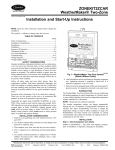
Installation and Start-Up Instructions
TABLE OF CONTENTS
Page
SAFETY CONSIDERATIONS...................................................1
INSTALLATION CONSIDERATIONS....................................1
INTRODUCTION.....................................................................1-2
INSTALLATION ......................................................................2-8
• Check Equipment And Job Site..................................................2
• Component Location And Wiring Considerations .....................2
• Install Components...................................................................2-3
• Install Zone Dampers...............................................................3-5
• Install Barometric Bypass Damper .............................................5
• Install Leaving Air Temperature (LAT) Sensor.........................5
• Install Heat Pump Temperature (HPT) Sensor ..........................5
• Final Wiring..................................................................5-8, 21-28
• Understanding Sequence Of Operation ...................................6-8
SYSTEM CONFIGURATION ..............................................8-12
• Equipment Controller Configuration .......................................8-9
• User Interface Configuration .................................................9-12
SYSTEM STARTUP AND CHECKOUT..........................12-13
• Enable Installer Setup Mode.....................................................12
• Check Damper And Sensor Operation ................................12-13
• Quick Check Of Equipment Operation ....................................13
• Longer Check Of Equipment Operation...................................13
FINAL INSTALLATION SETTINGS ...............................13-16
OPERATIONAL INFORMATION .........................................16
QUICK START.....................................................................16-17
QUICK PROGRAMMING OF COMFORT SCHEDULES.17
HOLD, OFF, OUT AND ALL ZONE................................17-19
SMART SENSOR OPERATION............................................ 18
TROUBLESHOOTING .......................................................19-20
NOTE: Read the entire instruction manual before starting the
installation.
This symbol → indicates a change since the last issue.
SAFETY CONSIDERATIONS
Improper installation, adjustment, alteration, service, maintenance,
or use can cause fire, electrical shock, or other conditions which
may cause personal injury or property damage. Consult a qualified
installer, service agency or your distributor or branch for information or assistance. The qualified installer or agency must use
factory-authorized kits or accessories when modifying this product. Refer to the individual instructions packaged with the kits or
accessories when installing.
Follow all safety codes and wear safety glasses. Have fire
extinguisher available. Read these instructions thoroughly and
follow all warnings or cautions attached to the unit. Consult local
and state building codes and Sheet Metal and Air Conditioning
National Association (SMACNA) for special installation requirements.
Recognize safety information. This is the safety-alert symbol .
When you see this symbol on the unit or in instructions and
manuals, be alert to the potential for personal injury.
Understand the signal words DANGER, WARNING, and CAUTION. These words are used with the safety-alert symbol. DANGER identifies the most serious hazards which will result in severe
personal injury or death. WARNING signifies hazards which
could result in personal injury or death. CAUTION is used to
identify unsafe practices which would result in minor personal
injury or product and property damage.
INSTALLATION CONSIDERATIONS
Before the actual installation of a zoning system can begin,
decisions need to be made to determine the number and location of
zones and sensors. This affects duct and damper selections. For
assistance with these decisions, consult the Zoning Design Guide
available from your distributor or branch.
This instruction covers the physical installation and start up of the
Comfort Zone II -B system. Use this instruction to guide the actual
installation process after all the air side decisions have been made.
1. Install User Interface and Remote Sensors in non-condensing
areas with ambients between 32°F and 120°F. Install Dampers
and Equipment Controller in non-condensing areas with
ambients between 32°F and 158°F.
2. A TXV is required on the indoor coil when used with all
residential split system equipment.
3. Use separate isolated transformer to supply power to Comfort
Zone II -B System (40 va minimum, class 2, field supplied).
4. Proper equipment and duct sizing are important in a zoned
system. Be sure to refer to the Zoning Design Guide for
assistance in making these selections.
TXV on indoor coil is required with all residential split
system equipment.
INTRODUCTION
The Comfort Zone II -B System allows air conditioning and
heating equipment to control temperatures and humidity in up to 8
distinct spaces or Zones within a building. Each zone has independent temperature settings.
The comfort temperature settings can change automatically
through the use of schedules. This allows Comfort Zone II -B to
change temperature settings in zones to reflect occupancy or usage.
For example, you can condition the bedrooms in a home from 5:00
PM through 7:00 AM or the kitchen from 3:00 PM through 6:00
PM. The Comfort Zone II -B System uses motorized air volume
control dampers (also called zone dampers) to regulate flow of
conditioned air into zones. In this manner Comfort Zone II -B can
selectively heat or cool certain portions of a building depending
upon space temperature requirements.
Each zone requires a motorized zone damper to control the air
supplied to it and a zone sensor to sense zone temperature. There
are 4 types of zone sensors available and they may be used in
combination:
Manufacturer reserves the right to discontinue, or change at any time, specifications or designs without notice and without incurring obligations.
Book 1 1 4 4
PC 101
Catalog No. 809-538
Printed in U.S.A.
Form ZONEKIT-14SI
Pg 1
12-99
Replaces: ZONEKIT-13SI
Tab 3a 5a 2a 5a
•
User Interface — Each installation has only 1 User Interface.
This is the command center for the entire system, and it will
typically be located in Zone 1 to sense and control the
temperature in this zone. If desired, a Remote Sensor may be
used to sense the Zone 1 temperature. This can give the
installer some flexibility in locating the User Interface to
another area.
•
Remote Sensor — This is a temperature sensor only, having no
additional user inputs.
needs to be located to properly measure the temperature in Zone 1.
If these 2 requirements conflict, a separate Remote Sensor can be
added for Zone 1. When Remote Sensor is connected to Zone 1
terminals (ZS1 and ZS1C) of Equipment Controller, the system
automatically switches to using this sensor for Zone 1 and ignores
the sensor within the User Interface. This arrangement allows User
Interface to be located at any convenient place within the home or
business, and only the Zone 1 Remote Sensor must be located in
Zone 1.
NOTE: The User Interface also controls humidity functions. If
the User Interface is not used to control Zone 1 temperature, it
must still be located in a suitable area where humidity control will
not be affected.
•
Smart Sensor — Any zone other than Zone 1 may use a Smart
Sensor. It provides a display of zone temperature and means to
adjust the desired temperature in that zone only. It also displays
the outdoor temperature and indoor humidity.
• Wireless Remote Sensor — This is a wireless and batteryoperated version of the Remote Sensor. It is used in locations
where it is not practical to route wires to the sensor location or
where it is desirable to move the sensor to different locations
within the zone. Wireless sensors have a range of 200 feet
through normal residential construction. However, their signals
will not reliably pass through foil insulation, foil vapor barriers,
or other metal objects. As with all radio signals, there may be
"dead spots" which limit the location of sensors. Moving the
sensor one foot in any direct may eliminate the "dead spot".
Be sure to select the desired sensor type for each zone. Standard
kits include only Remote Sensors. Other types must be purchased
separately. Installation Instructions for Smart Sensors and Wireless
Remote Sensors are included with them.
LOCATING SENSORS — For proper operation, each sensor
must accurately measure the temperature within its zone. Remember that zone sensors can be a combination of 4 different types as
described in introduction.
For accurate temperature measurement, the following guidelines
should be followed:
Sensor should be mounted:
• Approximately 5 ft (1.5m) from floor.
• Close to the center of its zone, preferably on an inside wall.
• On a section of wall without pipes or duct work.
Sensor should NOT be mounted:
•
Close to a window, on an outside wall, or next to a door leading
to the outside.
• Where it will be exposed to direct light and heat from a lamp,
sun, fireplace, or other temperature-radiating object which may
cause a false reading.
• Close to or in direct airflow from supply registers and return-air
grilles.
• In areas with poor air circulation, such as behind a door or in
an alcove.
The Remote Sensor terminals are not marked for polarity because
polarity is not important.
INSTALLATION
Step 1—Check Equipment and Job Site
INSPECT EQUIPMENT — File claim with shipping company,
prior to installation, if shipment is damaged or incomplete.
Step 2—Component Location and Wiring
Considerations
To prevent personal injury or possible equipment damage
disconnect power supply before routing wire.
WIRING CONSIDERATIONS — All wiring in the Comfort Zone
II -B system may be unshielded. Ordinary thermostat wire is ideal.
Use 22 gage or larger for normal wiring. Lengths over 100 ft
should use 20 gage or larger wire. Remote Sensors require only 2
conductors, but it is recommended that at least 4 conductors be
run. This will allow a Smart Sensor to replace the Remote Sensor
with no wiring changes at a later date.
All wiring must comply with national, local, and state codes.
LOCATING EQUIPMENT CONTROLLER — All wiring is run
back to the Comfort Zone II -B Equipment Controller. Select a
location near the furnace or fan coil where wiring from the User
Interface, each Remote Sensor or Smart Sensor, each damper
actuator, and the equipment itself can come together easily.
The User Interface requires 4 conductors, each damper actuator
requires 3 conductors. The connection to equipment (furnace or
fan coil) could require as many as 8 conductors for a multi-stage
installation. The leaving air temperature (LAT), heat pump temperature (HPT)—(used with heat pumps only), and outdoor air
temperature (OAT) sensors require 2 conductors each. The OAT
sensor may be able to be connected at the outdoor unit using
existing wiring. Refer to Installation Instructions included with the
OAT.
The Comfort Zone II -B System is approved for indoor use only
and should never be installed with any of its components exposed
to the elements. The Equipment Controller (and the zone dampers)
may be installed in any area where the temperature remains
between 32° and 158°F, and there is no condensation. The cover
must be installed to prevent damage from other sources. Do not
locate where it will be accessible to children. Avoid areas in which
the sound of relays energizing on the Equipment Controller may be
an annoyance. It may be mounted in either vertical or horizontal
position. Remember that wiring access is likely the most important
consideration.
Cables with excess conductors are acceptable. Cut off or fold back
and tape any unneeded conductors.
Plan the routing of wiring early to avoid possible problems later
on.
Remember all wires converge at the Equipment Controller, so its
location is important.
To prevent possible damage to Equipment Controller, do not
mount on plenum, duct work, or flush against furnace.
Step 3—Install Components
INSTALL EQUIPMENT CONTROLLER
LOCATING USER INTERFACE — The User Interface is the
command center for the Comfort Zone II -B system. It should be
located where it is easily accessible and visible to home or
business owner. It is also normally the Zone 1 sensor and as such
The Equipment Controller is designed so that wires can enter it
from behind, above, or below. Plan wire routing before mounting
Controller.
2
Step 4—Install Zone Dampers
1. Open doors or remove cover to access mounting holes
(remove the 2 Zone system cover from the left side first).
Proper selection and sizing of dampers is very important for proper
system operation. Be sure to consult the Zoning Design Manual for
assistance in making these selections. Selection and sizing information is not provided in this installation instruction.
2. Mount back plate to wall using screws and wall anchors
provided.
3. Level back plate and tighten screws.
If duct work requires multiple dampers for a single zone, up to 5
dampers may be wired in parallel. A multi-damper enabler is not
needed.
INSTALL USER INTERFACE
1. Open User Interface rear door (mounting base) to expose
mounting holes. Press back half of the right end inward and
then pull front and back halves apart at the right end to open.
The mounting base (the back half of the plastic) can be
separated from the User Interface body by snapping the hinge
apart.
For retrofit applications, older type dampers with their original
actuators may be used under the following conditions:
1. A single damper may be connected directly to a Comfort Zone
II -B output.
2. If multiple dampers are needed for a single zone, a multidamper enabler must be used.
a. Remove hinged cover by snapping apart its hinge.
b. Separate the main body from the mounting plate by
snapping its hinge apart.
Older type dampers having an extended shaft and driven by a
crank arm may be fitted with the new DAMPACT actuators for
quieter operation. Mounting is straightforward. Be sure to use 45°
actuators (part No. DAMPACT45DEG) with round dampers and
90° actuators (part No. DAMPACT90DEG) with rectangular
dampers. When new actuators are fitted to older dampers, multi
damper enablers are not needed and up to 5 actuators can be
connected in parallel to a single Comfort Zone II -B output.
c. Mount base before wiring and attaching remaining parts.
2. Route User Interface wires through large hole in mounting
base. Level mounting base against wall and mark wall through
2 mounting holes. Any thermostat cable of 4 or more
conductors may be used. Shielded cable is not needed.
3. Drill two 3/16-in. holes in wall where marked.
4. Secure mounting base to wall with 2 screws and anchors
provided, making sure all wires extend through hole in
mounting base.
Zone dampers may be installed in any position.
Install dampers so that actuator is visible for inspection and
accessible in the event it would ever need to be serviced. The black
mark on the end of damper shaft represents position of damper
blade.
5. Adjust length and routing of each wire to reach proper
terminal and connector block on mounting base with 1/4 in. of
extra wire. Strip only 1/4 in. of insulation from each wire to
prevent adjacent wires from shorting together when connected.
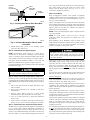
The 45 degree actuators on round ducts have their mechanical
stops set at 45 degrees. DO NOT CHANGE THIS SETTING.
Doing so will allow the actuator to close when it is trying to open.
If an actuator is removed, it must be properly aligned when it is
reinstalled. Do this by rotating the actuator and the blade to their
closed positions and then tightening the actuator to the shaft. This
assures alignment at the closed position. (Pressing the red blade
release button inside the actuator connection box releases the
motor and allows the actuator to be manually turned.)
6. Match and connect 4 wires to proper terminals of the
connector blocks. Recommended connection is RED to V+,
WHITE to VG, BLUE or YELLOW to RS+, and GREEN to
RS-.
Improper wiring or installation may damage the User Interface. Check to make sure wiring is correct before proceeding
with installation or turning on unit.
When dampers are located in an unconditioned space, condensation is likely to occur in cooling. Regular and severe
condensation will damage the actuator. To prevent condensation and losses, all dampers and ductwork in unconditioned
space must be insulated or otherwise protected.
7. Push any excess wire into wall and against mounting base.
Seal hole in wall to prevent air leaks. Leaks can affect
operation.
8. Snap hinge back together.
Whenever condensation might occur, it is recommended that
plastic actuator covers (Part#DAMPACTXXCOV) be used over
the actuator. These covers can help prevent condensation on
actuators by locking out ambient humidity. Insulation may be
applied over the cover to minimize heat transfer.
9. Close User Interface assembly making sure pins on back of
circuit board align with sockets in connector.
INSTALL REMOTE SENSORS
1. Separate the sensor and mounting back plate (with provided
screws and anchors). Squeeze the top and bottom of the cover
together firmly by grasping the raised top and bottom ridges.
This will release the cover.
To install, place the cover over actuator and seal in place over the
surrounding insulation with duct tape on all four sides. Sealing
need not be perfect because there will be positive pressure inside
the cover. Do not mount the dampers with their actuators hanging
directly beneath the ductwork. It is best to mount the actuator
facing in either the three or nine o’clock position.
2. Pull a 2-conductor wire through hole on right-hand side.
3. Recommended connection is BLACK to either terminal,
WHITE to remaining terminal. Stranded or common bell wire
may be used. Lengths up to 1000 ft will contribute no
noticeable error.
For specific duct types, follow instructions below:
ROUND METAL DUCT WORK
4. Align sensor case with base plate then press firmly until cover
snaps into place.
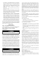
1. Crimp end of branch duct.
For installation of other sensor types, refer to Installation Instructions provided for them.
2. Slip end of zone damper over end of duct work. Use
self-tapping sheet metal screw to secure. (See Fig. 2.)
3
3. Properly seal joint using duct tape, mastic, or other approved
method. Do not allow mastic to come in contact with actuator.
4. Insulate damper using 1-1/2 in. to 2-in. insulation. (Check
your local codes.)
S-LOCK
NOTE: All zone dampers and duct work must be properly
supported according to local codes or SMACNA standards.
RECTANGULAR METAL DUCT WORK
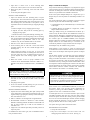
1. Make connections using S-lock and drives. (See Fig. 3.)
SUPPLY
AIR DUCT
2. Properly seal joint using duct tape, mastic, or other approved
method. Do not allow mastic to come in contact with actuator.
DRIVE
ZONE
DAMPER
AIRFLOW
A92478
1 1/2 " TO 2"
INSULATION
POSITION
INDICATOR
90
MOUNTING
HUB
AIRFLOW
Fig. 3—Rectangular Metal Duct Work
ANGULAR
ROTATION
STOPS
45
ACTUATOR
HOUSING
CLS
COM
OPN
0
QUICK BLADE
RELEASE
BUTTON
(RED)
MOUNTING
BRACKET
A95131
FIELD
INSTALLED
POWER WIRING
Fig. 4—Insulated Rectangular Metal Duct Work
Fig. 1—Damper 24-vac Connections
1
FLEXIBLE
DUCT
A95096
ZONE
DAMPER
/ 2 ″ STEEL STRAP
Fig 5—Round Flexible Duct Work
1/ 2 ″
A95130
A95132
STEEL STRAP
Fig. 2—Insulated Round Metal Duct Work
3. Insulate damper using 1-1/2 in. to 2-in. insulation. (Check
your local codes.) (See Fig. 4.)
ROUND FLEXIBLE DUCT WORK
1. Slip 1 end of flexible duct work over 1 end of zone damper.
(See Fig. 5.)
A95133
2. Secure flexible duct to zone damper using SMACNA or other
approved method.
Fig. 6—Insulated Round Flexible Duct Work
3. Properly seal joint using duct tape, mastic, or other approved
method. Do not allow mastic to come in contact with actuator.
RECTANGULAR FIBROUS GLASS DUCT WORK
1. Insert 1 end of zone damper into 1 end of fibrous glass duct
work approximately 2 to 3 in. (See Fig. 7.)
4. Insulate damper using 1-1/2 in. to 2-in. insulation. (Check
your local codes.) (See Fig. 6.)
2. Screw field-supplied screws and tabs into zone damper.
NOTE: All zone dampers and duct work must be properly
supported according to local codes or SMACNA standards.
3. Properly seal joint using duct tape, mastic, or other approved
method. Do not allow mastic to come in contact with actuator.
4
FIBROUS
GLASS
DUCTWORK
coil or may be located entirely inside the fan coil near the blower
inlet. Anchor firmly in place with cable ties so that it cannot
interfere with the blower wheel. (See Fig. 9, 10, or 11 for
connection to Equipment Controller.)
FIELD
SUPPLIED
SCREWS
ZONE
DAMPER
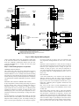
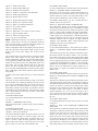
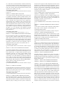
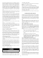
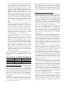
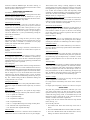
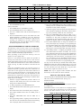
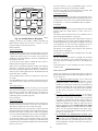
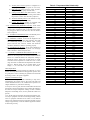
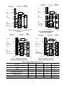
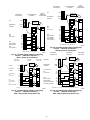
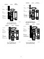
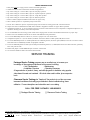
Step 8—Final Wiring
Bring all Equipment Controller wires together at Equipment
Controller. Make all connections as indicated on Fig. 9 (for 2-zone
installations), Fig. 10 (for up to 4-zone installations), or Fig. 11
(for up to 8-zone installations).
2″ TO 3″
A92480
Figures 15 through 42 show the connection between the Equipment Controller and the HVAC equipment. Select proper diagram
for your equipment and connect accordingly. This connection will
require as few as 4 or as many as 7 conductors. See Table 6 to
identify the correct wiring figure.
Fig. 7—Rectangular Fibrous Glass Duct Work
NOTE: Table 6 and wiring diagrams appear in sequence near the
end of this document.
1 1/ 2 ″ TO 2″
INSULATION
NOTE: It is good practice to mark each wire as the final
connection is made. This will preserve its identity if it is ever
disconnected.
When installing a 24-vac humidifier, connect it directly to the
HUM terminal on Equipment Controller, and C terminal of indoor
equipment. Do not use an external humidistat. All necessary
control is provided by Comfort Zone II -B.
A95134
Fig. 8—Insulated Rectangular Fibrous Glass
Duct Work
4. Insulate damper using 1-1/2 in. to 2-in. insulation. (Check
your local codes.) (See Fig. 8.)
Step 5—Install Barometric Bypass Damper
DO NOT connect furnace HUM terminal directly to Equipment Controller HUM terminal. This will bypass furnace
safety controls. See Low Voltage Wiring Diagrams and notes
for proper connection.
NOTE: The barometric bypass damper is a critical part of
Comfort Zone II -B System for controlling noise at minimum
airflow. A barometric bypass should be installed unless the duct
work and indoor unit have been sized for use without a bypass.
For proper installation, refer to Installation Instructions packaged
with barometric bypass.
When using an FK or FV series fan coil, connect DHUM
(dehumidify) output directly to DH terminal of fan coil. This
output may also drive a relay (connected with other side to C)
which can be connected to reduce fan speed in other types of
blowers. The relay will be energized when humidity is normal and
will de-energize when humidity is high, calling for reduced fan
speed.
Failure to properly install Leaving Air Temperature Sensor
can cause permanent damage to the HVAC equipment.
An LAT sensor must be connected in all systems. Both LAT and
HPT sensors must be connected in heat pump/fan coil systems.
The bypass should be installed according to local codes and
SMACNA standards. Be sure bypass is properly supported.
Step 6—Install Leaving Air Temperature (LAT) Sensor
Wiring Considerations
Locate LAT sensor in main supply trunk after heating and cooling
coil and before bypass damper and first branch. The LAT sensor is
radiant shielded to prevent heat from affecting correct air temperature.
Comfort Zone II -B treats all furnaces as if they were 2-stage. For
single stage equipment, connect to W1. The same holds true for
auxiliary heat in fan coils. (Refer to Fig. 15-42.)
With any 2-stage furnace, configure the furnace so that low heat is
controlled by W1 and high heat is controlled by W1 and W2
together. This means the internal algorithm is to be disabled. See
furnace instructions.
1. Drill a 1/4-in. hole at location in supply trunk where sensor
will be installed.
2. Insert sensor in hole and use as a template to mark the 2
mounting holes.
Some variable speed furnaces have a "zoning" setting. If such a
setting exists, it should be turned on. It forces the furnace to adjust
its airflow more frequently to accommodate the effects of damper
movement. See furnace instructions.
3. Drill two 1/16-in. holes to accept No. 6 screws through
pre-drilled holes in duct temperature sensor back plate.
4. Use 2 No. 6 sheet metal screws to mount duct temperature
sensor to unit.
Step 7—Install Heat Pump Temperature (HPT) Sensor
All 2-speed air conditioners and heat pumps need to be configured
so that Y1 controls low speed and Y1 and Y2 together control high
speed in both heating and cooling. This is usually done by
selecting the "zoning" position of the stage 2 latch pot. See 2-speed
equipment instructions.
The HPT sensor is required in all heat pump/fan coil installations.
It is not used in dual fuel(heat pump/furnace installation). It
measures the temperature of the air leaving the indoor coil. The
sensor is to be installed downstream of the indoor coil but before
the electric heaters. It can be installed through the wall of the fan
In 2-speed dual fuel applications (2-speed heat pump and furnace),
do not set the furnace interface jumper on the heat pump to ON,
even though its instructions say to do so. The necessary interlocking to keep both the heat pump and furnace from operating at the
same time is done by Comfort Zone II -B.
5. Connect sensor to 2-conductor wire using provided wire nuts.
(See Fig. 9, 10, or 11 for connection to Equipment Controller.)
5
2 ZONE EQUIPMENT CONTROLLER
P
NA
D
C
NA
G
DEF DEFROST
DEFROST
JUMPER NEEDED
FOR HEAT PUMP
APPLICATIONS
DHUM DEHUMIDIFY
HUM HUMIDIFY
DAMPER
FUSE
3A
OAT
OATC
LAT
LATC
HPT
HPTC
O REVERSING VALVE COOL
B REVERSING VALVE HEAT
RH HEATING TRANSFORMER
RC COOLING TRANSFORMER
SEE
FIGURES FOR
EQUIPMENT
WIRING
G FAN
W2 HEAT STAGE 2
W1 HEAT STAGE 1
Y2 COMPRESSOR STAGE 2
Y1 COMPRESSOR STAGE 1
24 VAC
ZONING
TRANSFORMER
WIRELESS
RECEIVER*
OUTDOOR AIR
TEMP SENSOR
LEAVING AIR
TEMP SENSOR
HEAT PUMP
TEMP SENSOR
D20
(LED)
C
RZ
USER INTERFACE
† COMMUNICATION
CLS1
COM1
OPN1
CLS2
COM2
OPN2
ZONE 1
DAMPER
ZONE 2
DAMPER
BUS
DAMPERS
CLS_ = CLOSE
COM_ = COMMON = 24VAC FROM RZ
OPN_ = OPEN
† COMMUNICATION
8
BUS
OPTION
SWITCHES
NOTE SWITCH
#8 IS AT TOP
1
NOTES:
REMOTE
SENSORS
V+
RS+
RSVG
RED
BLUE/YELLOW
GREEN
WHITE
V+
RS+
RSVG
RED
BLUE/YELLOW
GREEN
WHITE
OS1
OS1C
ZS2
ZS2C
V+
RS+
RSVG
SMART SENSORS*
V+
RS+
RSVG
OPTIONAL
ZONE 1
SENSOR†
ZONE 2
SENSOR
* = OPTIONAL COMPONENTS
† = INSTALLING ZONE 1 REMOTE SENSOR AT OS1 AND OS1C WILL OVERRIDE
TEMPERATURE SENSOR ON USER INTERFACE
†= COMMUNICATION BUS ARE IN PARALLEL WITH EACH OTHER
(EITHER CONNECTOR CAN BE USED)
A98082
Fig. 9—2-Zone System Wiring Diagram
ture must be raised 2°F in order for zone to be satisfied. In this
case, temperature "heating demand" for zone is 2°F. (72° minus
70°F.)
Otherwise, if space temperature in a zone rises above cooling set
point, then that zone needs to have heat removed from zone which
will lower space temperature back to cooling set point. For
example, if cooling set point is 76°F and space temperature is
77°F, space temperature must be lowered 1°F in order for zone to
be satisfied. In this case, "cooling demand" for zone is 1°F. (77°
minus 76°F.)
OUT FEATURE
A new feature called OUT can be selected via the OUT button.
When this selection is made, the system is being told that the
selected zone is unoccupied. It will normally supply no conditioning to an OUT zone. If zone temperature exceeds 85°F or goes
below 60°F, conditioning will be supplied to maintain the zone
within these limits.
OUT zones are also used to provide dehumidification when
cooling is not needed. During ’cool to dehumidify’ all OUT zones
are fully open.
The system will also use OUT zones to relieve the equipment
under overload conditions. If the total demand from all zones is
such that airflow is insufficient (or bypassing is excessive) this
condition will be sensed by the LAT or HPT temperature sensors.
When these temperatures begin to approach their limits, Comfort
Zone II -B will first begin to open dampers in the OUT zones to
relieve overload condition. The system will also monitor temperatures in the OUT zones and never allow them to become cooler
Carrier’s Comfort Heat system is now supported by Comfort Zone
II -B, with all the features of the Thermidistat™ Control. When
used with compatible variable-speed furnaces and fan coils,
controlled dehumidification in cooling and warm heat pump
heating are provided.
Step 9—Understanding Sequence of Operation
TEMPERATURE SET POINTS
The Comfort Zone II -B System uses 2 temperature set points for
each zone, the higher for cooling and the lower for heating. A
minimum difference of 2°F. is normally enforced between heating
and cooling set points, although this value may be adjusted by the
installer. Each set point may be manually adjusted or controlled by
a programmed time schedule established by the home or business
owner.
HEATING AND COOLING COMFORT SET POINTS
If space temperature is between heating and cooling set points for
the zone, then the zone is said to be "satisfied" with respect to
temperatures. When a zone is satisfied, no heating or cooling is
required. When all zones are satisfied, there is no demand and the
equipment is turned off. For example, if cooling set point is 76°F
and heating set point is 72°F, then a space temperature of 73°F is
assumed to be satisfactory and no heating or cooling of the zone is
required.
If space temperature in a zone falls below heating set point, then
that zone needs to have heat added to zone which will raise space
temperature back to heating set point. For example, if heating set
point is 72°F and space temperature is 70°F, then space tempera-
6
4 ZONE EQUIPMENT CONTROLLER
DEFROST
JUMPER NEEDED
FOR HEAT PUMP
APPLICATIONS
P
NA
D
C
NA
G
DEF DEFROST
DHUM DEHUMIDIFY
HUM HUMIDIFY
DAMPER
FUSE
3A
O REVERSING VALVE COOL
B REVERSING VALVE HEAT
RH HEATING TRANSFORMER
RC COOLING TRANSFORMER
SEE
FIGURES FOR
EQUIPMENT
WIRING
OAT
OATC
LAT
LATC
HPT
HPTC
WIRELESS
RECEIVER*
OUTDOOR AIR
TEMP SENSOR
LEAVING AIR
TEMP SENSOR
HEAT PUMP
TEMP SENSOR
G FAN
W2 HEAT STAGE 2
W1 HEAT STAGE 1
Y2 COMPRESSOR STAGE 2
Y1 COMPRESSOR STAGE 1
24 VAC ZONING
TRANSFORMER
D20
(LED)
C
RZ
CLS1
COM1
OPN1
CLS2
COM2
OPN2
CLS3
COM3
OPN3
CLS4
COM4
OPN4
ZONE 1
DAMPER
ZONE 2
DAMPER
ZONE 3
DAMPER
ZONE 4
DAMPER
USER INTERFACE
DAMPERS
CLS_ = CLOSE
COM_ = COMMON = 24VAC FROM RZ
OPN_ = OPEN
† COMMUNICATION
BUS
† COMMUNICATION
BUS
REMOTE
SENSORS
V+
RS+
RSVG
RED
BLUE/YELLOW
GREEN
WHITE
V+
RS+
RSVG
RED
BLUE/YELLOW
GREEN
WHITE
OS1
OS1C
ZS2
ZS2C
ZS3
ZS3C
ZS4
ZS4C
V+
RS+
RSVG
SMART SENSORS*
V+
RS+
RSVG
OPTIONAL
ZONE 1
SENSOR†
ZONE 2
SENSOR
ZONE 3
SENSOR
ZONE 4
SENSOR
8
1
NOTES:
OPTION
SWITCHES
NOTE SWITCH
#8 IS AT TOP
* = OPTIONAL COMPONENTS
† = INSTALLING ZONE 1 REMOTE SENSOR AT OS1 AND OS1C WILL OVERRIDE
TEMPERATURE SENSOR ON USER INTERFACE
†= COMMUNICATION BUS ARE IN PARALLEL WITH EACH OTHER
(EITHER CONNECTOR CAN BE USED)
A98083
Fig. 10—4-Zone System Wiring Diagram
4. Turn off equipment when all zones reach their set points.
than the coolest zone (in cooling) or warmer than the warmest zone
(in heating). This prevents over conditioning of OUT zones while
still using them to relieve an overload condition.
5. Leave dampers at their final positions while equipment is off.
6. If equipment does not run for 1 hour, it will fully open all
dampers.
Zones can be set to OUT at any time or OUT can be programmed
like any other temperature. The home or business owner can then
program OUT for times that the zone is not likely to be occupied.
When OUT is selected, both heating and cooling set points are
replaced by "--."
7. If any zone is more than 1½°F overconditioned, its damper
will be fully closed.
8. If any zone is more than 2°F. underconditioned (calling), its
damper will be fully open.
SEQUENCE OF EVENTS FOR NORMAL HEATING OR
COOLING CYCLE
This is the basic sequence of operation for the Comfort Zone II -B
system. The actual control of dampers, HVAC equipment, and
system fan will change with the configuration of system. Depending upon configuration, Comfort Zone II -B can control heat
pumps, furnaces, and dual fuel applications.
Given comfort set points and space temperature for zones within
system, Comfort Zone II -B will determine if active heating or
cooling is required. If so, Comfort Zone II -B will perform the
following:
CONTROL STRATEGY FOR HEATING / COOLING STAGES
1. Fully open 1 or more dampers and position others so that all
zones will be conditioned back to their set points at the same
time.
The Comfort Zone II -B system will attempt to minimize use of
additional stages of heating or cooling equipment.
Comfort Zone II -B controls multi-stage equipment in response to
the level of demand and the number of zones with demand. In
general, it tries to satisfy demand with a minimum number of
stages. In heat pump systems, where auxiliary heat is usually
expensive, a small extra demand is required to bring on auxiliary
2. Turn on equipment.
3. While equipment is on, continually make small adjustments in
damper positions so that all zones converge on their set points
at the same time.
7
8 ZONE EQUIPMENT CONTROLLER
DEFROST
JUMPER NEEDED
FOR HEAT PUMP
APPLICATIONS
P
NA
D
C
NA
G
DEF DEFROST
DHUM DEHUMIDIFY
HUM HUMIDIFY
DAMPER
FUSE
3A
O REVERSING VALVE COOL
B REVERSING VALVE HEAT
RH HEATING TRANSFORMER
RC COOLING TRANSFORMER
SEE
FIGURES FOR
EQUIPMENT
WIRING
OAT
OATC
LAT
LATC
HPT
HPTC
WIRELESS
RECEIVER*
OUTDOOR AIR
TEMP SENSOR
LEAVING AIR
TEMP SENSOR
HEAT PUMP
TEMP SENSOR
G FAN
W2 HEAT STAGE 2
W1 HEAT STAGE 1
Y2 COMPRESSOR STAGE 2
Y1 COMPRESSOR STAGE 1
24 VAC ZONING
TRANSFORMER
C
RZ
CLS1
COM1
OPN1
CLS2
COM2
OPN2
CLS3
COM3
OPN3
CLS4
COM4
OPN4
CLS5
COM5
OPN5
CLS6
COM6
OPN6
CLS7
COM7
OPN7
CLS8
COM8
OPN8
ZONE 1
DAMPER
ZONE 2
DAMPER
ZONE 3
DAMPER
ZONE 4
DAMPER
ZONE 5
DAMPER
ZONE 6
DAMPER
ZONE 7
DAMPER
ZONE 8
DAMPER
D20
(LED)
USER INTERFACE
†COMMUNICATION
BUS
NOTES:
RED
BLUE/YELLOW
GREEN
WHITE
V+
RS+
RSVG
SMART SENSORS*
†COMMUNICATION
DAMPERS
CLS_ = CLOSE
COM_ = COMMON = 24VAC FROM RZ
OPN_ = OPEN
BUS
V+
RS+
RSVG
REMOTE
SENSORS
OPTION
SWITCHES
NOTE SWITCH
#8 IS AT TOP
RED
BLUE/YELLOW
GREEN
WHITE
ZS3
ZS3C
ZS4
ZS4C
OPTIONAL
ZONE 1
SENSOR †
ZONE 2
SENSOR
ZONE 3
SENSOR
ZONE 4
SENSOR
ZS5
ZS5C
ZS6
ZS6C
ZONE 5
SENSOR
ZONE 6
SENSOR
ZS7
ZS7C
ZS8
ZS8C
ZONE 7
SENSOR
ZONE 8
SENSOR
OS1
OS1C
ZS2
ZS2C
8
1
V+
RS+
RSVG
V+
RS+
RSVG
* = OPTIONAL COMPONENTS
† = INSTALLING ZONE 1 REMOTE SENSOR AT OS1 AND OS1C WILL OVERRIDE
TEMPERATURE SENSOR ON USER INTERFACE
†= COMMUNICATION BUS ARE IN PARALLEL WITH EACH OTHER
(EITHER CONNECTOR CAN BE USED)
Fig. 11—8-Zone System Wiring Diagram
A98084
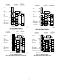
below. Using a pen or pencil, set each switch to its proper state.
ON is to the left and is the factory setting. OFF is to the right. Fig.
12 is a pictorial drawing of this selector switch.
heat. This acts to prevent the unnecessary use of auxiliary heat. In
addition, when an outdoor sensor is attached, the system can be set
to lock out auxiliary heat for outdoor temperatures above an
installer selectable value. This will be covered under System
Configuration.
Switch 1—Selects AC or HP.
ON—Selects AC.
OFF—Selects HP.
SYSTEM CONFIGURATION
Comfort Zone II -B must be configured to match the type of
equipment connected to it. In addition, there are several choices of
configuration based on how the user wants the system to operate.
Configuration is done in 2 parts. First is the setting of 8 DIP
switches on the Equipment Controller. The second is a group of
software selections made via User Interface. Follow the sequence
below for easy setup.
Switch 2—Selects single- or 2-speed compressor.
ON—Selects single speed.
OFF—Selects 2 speed.
Switch 3—Selects 3-stage electric heat. Equipment must include
FK or FV series fan coil with single-speed heat pump and properly
selected 3-stage electric heater.
ON—Normal 1- or 2-stage electric heat.
OFF—Special 3-stage electric heat.
Configuration of the Equipment Controller is done first with the
power off. Then power is applied and the User Interface is
configured with power on.
NOTE: A DIP switch module is oriented with switch 1 at the
bottom and switch 8 at the top. Refer to Fig. 12 for switch
orientation and labels.
Step 1—Equipment Controller Configuration
Switch 4—Selects Smart Recovery in both heating and cooling.
The system starts adjusting temperature 1-1/2-hours earlier than
selected recovery time so it will arrive at new temperature at
selected time.
ON—Smart recovery.
OFF—Normal recovery.
Located near bottom of Equipment Controller circuit board, there
is an 8 section DIP switch. The use of each switch is described
Switch 5—Zone system address selection. When 2 zoning systems
are connected together, the second system should be set to OFF.
8
NORM
8
DUAL FUEL
NORM
7
DISABLE LOW
TEMP COOLING
NORM
6
INSTALLER TEST MODE
NORM
5
ADDRESS 11
SMART
RECOVERY
4
NORM
NORM
3
3 STG HEAT
1 SPD
2
2 SPD
AC
1
HP
ON
(CLOSED)
OFF
(OPEN)
Turn on power to the zoning system by applying power to its
24-vac transformer. When power is first applied to Comfort Zone
II -B the Equipment Controller immediately begins positioning all
dampers to fully open by running each damper motor in the open
direction for 15 sec. This is done in succession, 2 zones at a time,
starting with Zone 1. The time required will be 15 sec for each pair
of zones. Remember that the system automatically determines the
number of zones by detecting the presence of zone sensors.
At power up the User Interface displays all segments for a few sec.
This is followed by the selected system type for an additional few
sec. The system type shows as follows:
1. AC—1-Speed Air Conditioner
2. HP—1-Speed Heat Pump
NOTE:
Switch factory
default is closed.
3. A2—2-Speed Air Conditioner
4. H2—2-Speed Heat Pump
5. HS—1 or 2-Speed Heat Pump with 3-Stage Auxiliary Heat
Fig. 12—DIP Switch Settings
A98183
6. dF—Dual Fuel with 1-Speed Heat Pump
7. d2—Dual Fuel with 2-Speed Heat Pump
ON—Normal single system (address = 01).
OFF—Address selection for second zoning system.
Power-on check of the User Interface itself can be done by
separating the User Interface from its backplate and then reconnecting it by attaching the 2 parts. This will allow observation of
the User Interface at power up.
Switch 6—Select installer test mode to assist in checking out the
system. See Starting System.
ON—Selects normal operation.
OFF—Selects installer test mode.
Several installer select options are set using the User Interface
keypad.
Switch 7—Enables or prevents cooling when outdoor temperature
is below the value selected by software Configuration Option 6. To
limit low temperature cooling, first set this switch to OFF and then
select 55, 50, or 45 degrees farenheit with Configuration Option 6.
Requires outdoor air temperature sensor.
ON—Cooling enabled at all temperatures.
OFF—Low temperature cooling disabled.
These configuration options, like DIP switch settings, are intended
to be selected at installation and are normally not modified by
home or business owner. These options are not discussed in the
Owner’s Guide and therefore must be made as part of the
installation. A special procedure allows entry into configuration
mode. Comfort Zone II -B will automatically exit this mode if no
button is pressed for 3 minutes. While in the configuration mode,
configuration choices can be made. In addition, LAT and HPT
temperatures as well as all damper positions can be viewed. A brief
description of each is given below, followed by instructions on
how to make the selection.
Switch 8—Dual fuel selection for systems with heat pump and
furnace.
ON—Selects normal system.
OFF—Selects dual fuel system.
→
Not all option numbers are used in this product. Options will only
appear on the User Interface if they are used in the particular
application, i.e., auxiliary heat lockout temperatures will appear
with heat pump selections, but not with AC/furnace selections.
Option numbers between 1 and 29 are common to all wall mounted
controls. Option numbers 30 and above are unique to zoning
systems.
All dual fuel installations must be equipped with a high
pressure switch to turn off the compressor under a high indoor
coil pressure situation.
The high pressure switch protects compressor and indoor coil
from overpressure which would occur if a failure or wiring
error resulted in the heat pump and furnace operating at the
same time.
Also, an outdoor temperature sensor must always be included
in dual fuel installations. If not, an E3 error message will
appear. See Error Messages in the Troubleshooting section.
TO ENTER THE CONFIGURATION MODE:
Press and hold FAN button for approximately 10 sec until room
temperature and set point displays change to 2 numbers. You are
now in the configuration mode.
CONFIGURATION OPTIONS:
Step 2—User Interface Configuration
Option 2—Clean filter timer
The User Interface is configured via a group of selections made
through the keypad in a special configuration mode. Before the
equipment is operated, the system must be properly configured.
Make sure this step is not left out.
Option 3—Fahrenheit or Celsius
Before turning power on to the zoning system, disable the system
equipment itself by either turning off its main power or by
temporarily disconnecting its 24-vac power at the RC and RH
terminals of the Equipment Controller. This will allow the zoning
system only to operate. Go through the following steps with the
equipment power off.
Option 6—Low ambient cooling lockout temperature
By this time 8 DIP switches on the Equipment Controller should
be properly set.
Option 13—Zone temperature offset adjustment
Option 4—Fan (G) ON with W
Option 5—Variable speed ICM motor
Option 7—Variable speed superdehumidification
Option 8—Auxiliary heat lockout Temperature
Option 11—Dual fuel crossover temperature
Option 12—Defrost heat selection
Option 14—Heat/cool dead band adjustment
9
Option 15—Enable AUTO mode
Option 16—Enable Comfort Heat mode
AVAILABLE SELECTIONS:
Use UP or DOWN buttons to alternate between OF (off) and ON.
Option 18—Humidity offset adjustment
OPTION 5—VARIABLE SPEED (ICM) BLOWER
Option 19—Outdoor air temperature offset adjustment
If the furnace or fan coil contains a variable speed ICM blower, set
this option ON. For normal (PSC) blowers, set to OF (off). This
selection enables the system to use Comfort Heat features available only with the ICM blower. Factory default is OF (off).
Option 20—Enable programmable fan
Option 30—Display damper positions
Option 31—Display HPT temperature reading
Option 32—Display LAT temperature reading
AVAILABLE SELECTIONS: Use UP or DOWN buttons to
alternate between OF (off) and ON.
Option 33—Select LAT shutdown temperature
OPTION 6—COOLING LOCKOUT TEMPERATURE
Option 34—User Interface address
This option allows selection of the outdoor temperature below
which cooling is not allowed. DIP switch 7 still enables or disables
this function, but this option allows setting its temperature. If DIP
switch 7 is ON (cooling is enabled at all outdoor temperatures),
Option 6 will display OF and cannot be changed. If DIP switch 7
is OFF (cooling can be disabled below a selected temperature),
Option 6 will allow the selection of 45, 50 or 55 degrees F. For all
residential equipment, select 55 degrees. For light commercial
equipment, select minimum outdoor cooling temperature from
equipment instructions. Factory default is 55.
Option 35—Disable zoning
Option 36—Select HPT or LAT sensor to monitor cooling
Option 37—Ignore LAT/HPT safeties
Option 38—Select auto changeover time
(1,9,10,17,21-29 are not applicable)
NOTE: If END button is pressed or if no button is pressed for 3
minutes, Comfort Zone II -B will exit configuration mode and
return to normal operation. To re-enter configuration mode, FAN
button must be pressed and held for 10 sec again.
AVAILABLE SELECTIONS:
Use the UP and DOWN buttons to move between 45, 50 and 55.
While in configuration mode, the large display shows the selection
which has been made and the smaller display (COOL set point
display) shows current option number. One of these will be
flashing.
OPTION 7—VARIABLE SPEED SUPER DEHUMIDIFICATION
This function only operates with selected Comfort Heat compatible furnaces and fan coils. Refer to furnace or fan coil instructions. Option 5 must be set to ON for this option to appear. When
there is a ’cool to dehumidify’ demand (a dehumidification demand
but no cooling demand), the blower CFM is reduced to a minimum
to obtain maximum dehumidification. While a ’cool to dehumidify’
demand exists, the equipment is cycled ON for 10 min. and then
OFF for 10 min. The reduced blower CFM is produced by a Y
signal without a G signal. ON enables this function. Factory
default is OF.
The up and down buttons are used both to move between available
options and to make selection for each option. When option
number (small display) is flashing, the up and down buttons adjust
it, moving between available option numbers. After desired option
number has been selected, press SET TIME/TEMP button. The
large display will now flash, indicating that the up and down
buttons now control available choices within that option. Each
press of the SET TIME/TEMP button switches between available
option (small display) and available selections within each option
(large display).
AVAILABLE SELECTIONS:
Use UP or DOWN buttons to alternate between OF (off) and ON.
Available options and available selections for each are described
below.
OPTION 8—AUXILIARY HEAT LOCKOUT TEMPERATURE
SELECTION
OPTION 2—CLEAN FILTER TIMER
This option is available only with heat pump and dual fuel systems.
In heat pump systems, auxiliary heat is prevented from coming on
while outdoor temperature is above the selected value. In dual fuel
systems, the furnace is prevented from operating while outdoor
temperature is above the selected value. This temperature must be
set higher or equal to that of option 11. (See option 11 below.)
Outdoor temperatures of 5, 10, 15, 20, 25, 30, 35, 40, 45, 50, or
55°F or OF (off) may be selected. If OF (off) is selected, outdoor
temperature does not affect system operation. Factory default is
OF (off).
Select hours of blower operation (heating, cooling, or fan) before
CLEAN FILTER icon is displayed. With OFF selected, icon will
never come on, disabling this feature. Time selection can be from
400 to 3600 hours by selecting numbers 1 through 9. (Time is
400X number selected.) Factory default is 2 (800 hours). Recommended selections are: disposable filter—400 to 800 hours, media
filter—1200 to 1600 hours, or electronic air cleaner—1600 to 2400
hours of blower operation.
AVAILABLE SELECTIONS:
Use UP and DOWN buttons to alternate between OF (off) and 1 to
9 in steps of 1.
AVAILABLE SELECTIONS:
Use UP and DOWN buttons to move between 5 and 55 or OF (off)
in steps of 5.
OPTION 3—FAHRENHEIT OR CELSIUS
Select between Fahrenheit or Celsius operation. Factory default is
Fahrenheit.
OPTION 11—DUAL FUEL CROSSOVER TEMPERATURE
SELECTION
AVAILABLE SELECTIONS:
Use UP or DOWN buttons to alternate between F or C.
This option is only available with dual fuel systems. While outdoor
temperature is below the selected value, only the furnace is used
for heating. This option must be set lower than or equal to that of
option 8. (See option 8 above.) If the temperature selections of
option 8 and 11 are set to the same value, a dual fuel system will
use the heat pump only above this temperature and the furnace
only below this temperature. If the selections are different, the
range between the 2 selections will use the heat pump as the first
stage and the furnace as the second stage. Once the furnace comes
OPTION 4—FAN (G) ON WITH W
This selection determines whether the G (fan) output is to be ON
or OFF when any W (furnace or strip heat) output is ON. Most
furnaces and fan coils manage their own blowers and do not
require a separate G signal. For these applications, select OFF.
Some auxiliary heaters require a separate G signal to turn on the
blower. In this case, select ON. Factory default is OFF.
10
removal of the G signal) for outdoor temperatures between 12 and
40 degrees F., providing warmer leaving air temperatures. For heat
pumps with electric aux heat and outdoor temperatures below 12
degrees F., any heat call is accompanied by a W1 signal, bringing
on the first stage of aux heat to again increase leaving air
temperature. Factory default is OF (off).
on, it will remain on until the demand is satisfied. The following
cycle will start with the heat pump. Outdoor temperatures of 5, 10,
15, 20, 25, 30, 35, 40, 45, 50, or 55°F or OF (off) may be selected.
If OF (off) is selected, outdoor temperature does not affect system
operation. Factory default is OF (off).
AVAILABLE SELECTIONS:
Use UP and DOWN buttons to move between 5 and 55 or OF (off)
in steps of 5.
AVAILABLE SELECTIONS:
Use UP or DOWN buttons to alternate between OF (off) and ON.
OPTION 12—DEFROST HEAT SELECTION
OPTION 18—HUMIDITY OFFSET ADJUSTMENT
A new feature that allows heat pump defrost cycles to always run
to completion and includes a software selectable amount of aux
heat during defrost. The equipment controller now senses 24vac on
the O line (which it did not put there) during a defrost. In response
to this, it maintains the Y signal as long as the O signal exists,
assuring defrost runs to completion. It now can also turn on W1
and/or W2 during defrost to control the amount of defrost heat.
Option 12 makes this selection. Select O for no heat, 1 for W1 on,
2 for W1 and W2 on, and 3 for W2 only on. This last selection is
only available if 3-stage heat is selected by turning DIP switch 3
off. When 1, 2 or 3 are selected, no wire should be connected
between the W terminals of the heat pump and the indoor unit.
Factory default is 0.
Like the zone temperature offset, the humidity reading can be
offset by plus or minus 10% in 1% steps. This offset adjusts the
humidity sensor output and therefore affects both humidify and
dehumidify performance. Factory default is 0.
AVAILABLE SELECTIONS:
Use UP and DOWN buttons to move between -10 and 10 in steps
of 1.
OPTION 19—OUTDOOR TEMPERATURE OFFSET ADJUSTMENT
Use this option to offset the outdoor temperature reading within a
range of plus or minus 5 degrees F. Factory default is 0.
AVAILABLE SELECTIONS:
Use up and down buttons to move between -5 and 5 in steps of 1.
AVAILABLE SELECTIONS:
Use UP and DOWN buttons to move between 0, 1, 2, or 3.
OPTION 20—ENABLE PROGRAMMABLE FAN
This option allows the blower to operate continuously (fan = ON)
during the day and automatically (fan = AUTO) at night. When
enabled, if the fan mode is set to ON, it will operate in AUTO
during the Zone 1 SLEEP period. Factory default is OF (off).
OPTION 13—ZONE TEMPERATURE OFFSET ADJUSTMENT
Each zone temperature reading can be independently offset by up
to plus or minus 5 degrees F. While Option 13 is selected, the
NEXT ZONE button moves between zones and the UP and
DOWN buttons select an offset value between -5 and +5 degrees
F in 1 degree F steps. The offset number is added to the actual zone
temperature to produce the offset zone temperature, which is
displayed and used by the system. Factory default value is 0.
OTHER AVAILABLE SELECTIONS:
Still using UP or DOWN buttons to alternate between OF (off) and
ON.
Options 30, 31, and 32 allow direct viewing of the temperatures of
the HPT and LAT sensors and the positions of all zone dampers.
They are useful for setup and troubleshooting. When these options
are selected, the temperatures or positions appear on the large
display. All other system operation is unchanged. When Option 30
is selected, use the NEXT ZONE button on the User Interface to
move between zones. Closed position is 0. Fully open is 15.
Temperature above 100°F are shown as the amount above 100.
AVAILABLE SELECTIONS:
Use UP and DOWN buttons to move between -5 and 5 in steps of
1.
OPTION 14—HEAT/COOL DEADBAND ADJUSTMENT
The minimum allowable difference between the heat and cool set
points can be selected to any value between 0 and 6 degrees F. The
factory default value is 2. Higher numbers provide less precise
temperature control but save energy. Lower numbers provide
comfort with more energy use. If the deadband is set to less than
2, the mode is set to auto changeover, and the auto changeover
timer is small (see Option #38), continuous alternating heat and
cool cycles may occur. This wastes energy, but may be desired to
reduce humidity. When used with the ’COOL TO DEHUMIDIFY’
selection, effective cooling with reheat can occur.
OPTION 30—DISPLAY DAMPER POSITIONS
Previously, Options 21 through 28 were used to view Zone 1
through Zone 8 damper positions. Now, Option 30 is selected for
all damper positions and the NEXT ZONE button is used to move
between the zones. This saves option numbers and makes scanning
damper positions easier.
OPTION 31—DISPLAY HPT TEMPERATURE READING
OPTION 32—DISPLAY LAT TEMPERATURE READING
AVAILABLE SELECTIONS:
Use UP and DOWN buttons to move between 0 and 6 in steps of
1.
OPTION 33—SELECT LAT SHUTDOWN TEMPERATURE
This option selects maximum allowable LAT in furnace and fan
coil auxiliary heat installations. Equipment will be turned off if its
LAT exceeds selected value. Values are 15, 20, 25, 30, 35, 40, 45,
50, 55, 60, 65, 70, or 75 corresponding to temperatures of 115° to
175°F. As LAT nears selected limit, actions are taken by the
system to try to reduce the LAT. These include staging down
multi-stage equipment and limited conditioning of OUT zones.
OPTION 15—ENABLE AUTO MODE
In some applications, auto changeover from heat to cool may not
be desired. Option 15 selects ON or OF (off) for auto changeover.
When OF, the AUTO mode icon never appears, disabling the
AUTO mode. Factory default is ON.
AVAILABLE SELECTIONS:
Use UP or DOWN buttons to alternate between OF (off) and ON.
When the LAT temperature approaches its limit, OUT zone
dampers progressively open, allowing more airflow into the duct
system. The temperatures of the OUT zones are also monitored. As
any OUT zone approaches the temperature of the most conditioned
zone, its damper closes again, preventing the OUT zone from
being over conditioned. If OUT zones are not available and LAT
temperature cannot be maintained at a safe value, the system will
OPTION 16—ENABLE SUPER COMFORT HEAT MODE
The Comfort Heat operation is the same as that for the Thermidistat. This selection is only available if heat pump (DIP switch 1)
and variable speed blower (Option 5) selections are already made.
While heat pump is heating, the blower speed is reduced (by
11
shut down the equipment when the LAT temperature reaches its
limit. If the equipment is shut down by a LAT or HPT limit trip,
the small ’equipment on’ triangle on the display will be flashing to
indicate this condition. Continuous fan is energized during a
LAT/HPT Limit Trip. This is true for both heating and cooling. As
with earlier Comfort Zone systems, temperature set here was
temperature where actions were started. Shutdown temperature
was 20°F higher than selected temperature. Therefore a setting of
155°F on Comfort Zone I is equivalent to 175°F on Comfort Zone
II -B.
AVAILABLE SELECTIONS:
Use UP or DOWN buttons to alternate between OF (off) and ON.
NOTE: ON is for temporary use only.
OPTION 38—SELECT AUTO CHANGEOVER TIME
This option selects a 5 to 30 minute time delay between heat and
cool while in auto changeover mode. System must have no demand
in current mode for selected time before changeover between
heating and cooling is allowed. Factory default is 30 minutes.
AVAILABLE SELECTIONS:
Use UP and DOWN buttons to move between 5 and 30 in steps of
5.
Heat pump temperature limit for shut down is fixed at 115°F and
cooling LAT temperature limit for shut down is fixed at 40°F
(down from Comfort Zone I which was 45°F.)
SYSTEM STARTUP AND CHECKOUT
Fan coils vary greatly in their LAT (leaving air temperature)
because of variations in the size of their heaters and their air flow.
This makes proper selection of LAT limits difficult. A value of 50
(150 °F limit) should be adequate. After the system is in operation,
LAT can be monitored via User Interface (configuration option 31
or 32) to check actual operating temperature. For furnaces select a
value of 75°F plus the rated maximum temperature rise from the
furnace nameplate. Factory default is 50 (or 150°F).
Comfort Zone II -B is designed with built-in checkout capability
for both the equipment and the zoning system. Use the sequence
below for trouble free setup. When it is time to start up system for
the first time, you may want to check out the zoning system first
and the equipment second or to reverse the process, checking
equipment first and zoning system second. Either way is acceptable.
AVAILABLE SELECTIONS:
Use UP and DOWN buttons to move between 15 and 75 in steps
of 5.
The following sequence checks out zoning system first. If you
wish to check equipment first, proceed to Step 4 below. Then, after
equipment is operating properly, return to Steps 1, 2, and 3 to
check out zoning system.
OPTION 34—USER INTERFACE ADDRESS
Step 1—Enable Installer Setup Mode
When 2 Comfort Zone II -B systems are connected together on the
same bus, each must have a different address. Address 01 is used
for single systems. Address 11 is selected for second User
Interface when present. Factory default is 01.
Select installer setup mode at the Equipment Controller by moving
DIP switch No. 6 to the OFF position. (See Fig. 12.) This may be
done with power on or off. This mode is indicated by InSt
appearing in the User Interface clock display. In this mode
several special features are available to assist in the setup/checkout
process:
AVAILABLE SELECTIONS:
Use UP or Down buttons to alternate between 01 and 11.
OPTION 35—DISABLE ZONING
a. When a zone is selected with the NEXT ZONE button, its
damper opens fully and all other dampers close.
When this option is selected, all dampers go fully open and zone
1 sensor (normally User Interface itself) becomes the sensor for the
entire home or business. In effect, the zoning system disappears
and is replaced by a single thermostat. In this mode, the ZONE X
where X is the zone number is not displayed. Factory default is OF
(off), zoning enabled. This option is used to check out the system
equipment. The User Interface acts as normal thermostat.
b. The selected zone’s temperature appears on the large
display.
c. The FAN button turns the blower ON or OFF.
d. The MODE button operates HEAT, COOL, or EHEAT for
2 minutes and then returns automatically to OFF. No
demand from the zones is needed to bring on the
equipment in installer setup mode.
AVAILABLE SELECTIONS:
Use UP or DOWN buttons to alternate between OF (off) and ON.
Step 2—Check Damper and Sensor Operation
OPTION 36—SELECT HPT OR LAT SENSOR TO MONITOR
COOLING
At the User Interface, set the mode to OFF using the MODE
Button to make sure cooling or heating outputs are not turned on.
Use the FAN button to turn on the blower by selecting ON (not
AUTO) under the fan icon. This will start the blower (if its supply
power is on). Use the NEXT ZONE button to select ZONE 1 above
the large display. This will open Zone 1 fully and close all other
zones. It will take the system 15 sec for each zone to complete this
process.
Previously, the LAT sensor, located in the leaving air path, was
always used to monitor cooling leaving air temperature. There are
some applications where the HPT sensor, located just downstream
of the coil, is better suited to measure the cooling leaving air
temperature. This option allows the installer to make this selection.
AVAILABLE SELECTIONS:
Use UP or DOWN buttons to alternate between LA (use LAT
sensor) and HP (use HPT sensor).
You may now physically observe the dampers to verify their
positions are correct (and check for air blowing out all Zone 1
registers only). The large display reads the temperature in Zone 1.
Use this opportunity to verify the Zone 1 sensor is properly
connected and is located in Zone 1 by breathing on the Zone 1
sensor and observing the temperature change. Remember, the
Zone 1 sensor is normally inside the User Interface but a remote
sensor may be used.
OPTION 37—LAT/HPT SAFETIES
Leaving this selection ON can cause permanent damage to
HVAC equipment
Use the NEXT ZONE button to select Zone 2 and repeat the above
process. Continue through all zones. When finished, you will have
verified that all the dampers and zone sensors are properly
connected and working.
This option, when ON, tells the system to ignore the LAT and HPT
temperature information. It should only be used for troubleshooting and to allow temporary operation with a failed or missing
sensor until the sensor can be replaced. Factory default is OF (off).
12
Step 3—Quick Check of Equipment Operation
Comfort Zone II -B provides superior convenience and features.
When installing a 24-vac humidifier, connect it directly to the
HUM terminal on the Equipment Controller and C terminal of
indoor equipment.
Either this or the next step (Step 4) may be used for initial startup.
This check runs equipment for only 2 minutes on each stage and is
adequate to see that each stage comes on properly. For temperature
rise, charge levels, etc. use the longer check, or disable zoning
feature.
Be sure installer setup is still selected (Equipment Controller DIP
switch No. 6 is OFF).
DO NOT connect furnace HUM terminal directly to Equipment Controller HUM terminal. This will bypass furnace
safety controls. See Low Voltage Wiring Diagrams and notes
for proper connection.
At User Interface, select HEAT mode. The first stage of heat will
come on immediately (no temperature demand is needed). For a
heat pump, this will be Y1 and G. For an air conditioning system,
this will be W1. The first stage will remain on for 2 minutes. Then
the second stage of heat will come on for 2 minutes. This will be
Y1, Y2, and G for a heat pump, or W1 and W2 for an air
conditioning system. At the end of 4 minutes, equipment will turn
off and mode will automatically return to OFF. If mode is set to
OFF at any time during 4 minutes, equipment will turn off
immediately. Note that single stage system (heat or cool) will
remain on for full 4 minutes because there will be no connection
to Y2 or W2.
A humidity sensor is built into the User Interface to monitor and
control relative humidity. The HUM output will control any
humidifier with a 24-vac input. A humidify set point can be set to
any value between 10 percent and 45 percent or can be turned off.
When the humidity drops 2 percent below the set point, the HUM
output is activated to turn on a humidifier. When the humidity rises
2 percent above the set point, the HUM output will turn off.
When an outdoor air temperature sensor is attached, an automatic
humidity level adjustment can be selected. This selection provides
a 1 percent reduction in the humidity set point for every 2 degrees
reduction in outdoor temperature. The set point can be changed at
any time, and it will then automatically adjust itself up and down
with changes in outdoor temperature. In no case will the set point
go above 45 percent or below 10 percent. This feature is to prevent
sweating of windows in very cold weather while allowing higher
humidity levels in warmer weather.
The same applies to COOL. When selected, cooling will come on
immediately with no need for temperature demand. First stage will
be Y1, G (and O if a heat pump) and will run for 2 minutes. Then
Y1, Y2, G (and O if a heat pump) will come on for next 2 minutes.
At the end of 4 minutes equipment will turn off and mode will
return to OFF.
In a heat pump system, EHEAT may also be selected at User
Interface. This will turn on W1 only for first 2 minutes and then
W1 and W2 for the second 2 minutes. The compressor will not run.
As above, equipment may be turned off at any time during the 4
minutes by setting mode to OFF.
Another selection involves the interlocking of the HUM output to
heating or fan operation. The HUM output can be set to come on
only when there is a humidity demand and any heat output is on
(heat pump, furnace, or auxiliary heat). A second setting allows the
HUM output and the blower to turn on when there is humidity
demand. This selection allows humidification with the fan when
there is a no heat call. In no case will the HUM output be on
without either heat or fan.
For all operation in this installer setup mode, no demand is needed,
no compressor timeguard exists, and no temperatures are monitored. This means there is no protection for equipment, and this is
the reason that operation is limited to 4 minutes.
It may be advisable to configure the humidity control as part of the
installation process. Following is a brief description of the humidify setup process. It is also covered in the Owner’s Manual.
When leaving this step, be sure to return installer setup switch
(Equipment Controller DIP switch No. 6) to ON position. This will
enable normal operation.
There are 5 selections for humidification in the heating mode:
When any output is turned on, a red LED on the Equipment
Controller board adjacent to the output’s connection terminal is
also turned on. This can be used at any time to monitor the state of
the Equipment Controller outputs, even if the equipment is not yet
connected or powered. Remember, the DEHUM output is a reverse
logic relay. This means its LED will be ON while there is no
dehumidify demand. See dehumidification section.
1. Normal Humidify
2. Fan Humidify
3. Auto Humidify
4. Auto and Fan Humidify
5. OFF
Step 4—Longer Check of Equipment Operation
Humidification Setup
When more detailed tests need to be made on equipment, the 2 or
4 minute run time provided in Step 3 may not be adequate. By
selecting disable zoning mode (turn Option No.35 to ON under
User Interface configuration), system operates like a standard
thermostat system. All dampers go fully open, and the zone which
is displayed on User Interface provides set points. This zone’s
temperature is the only controlled temperature. Equipment will
operate as if it were being controlled by a single thermostat in the
displayed zone. Use this option to check out equipment as you
would with a normal thermostat. When finished, be sure to return
to the configuration mode and turn Option No.35 OFF to enable
normal zoning operation.
FINAL INSTALLATION SETTINGS
Humidification Description
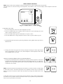
To make a humidification selection or change the humidity (hu) set
point, a 2-button keypad press is required. Press SET TIME/TEMP
and FAN buttons simultaneously (indicated on keypad by the RH
symbol) to enter humidity mode. Either hu (humidify) or dh
(dehumidify) will appear in the clock display. Use the SET
TIME/TEMP button to select hu. The actual humidity now appears
in the large display, the humidify set point appears in the heat set
point display, and the small triangle icon below the set point is
turned on when the humidify output is active. The UP and DOWN
buttons now adjust the humidify set point and the MODE button
scrolls through the 5 available humidification modes. These are
described below. Table 1 shows the display indication for each of
the 5 humidification modes.
1. Normal Humidify Mode—This is the factory default. In
Normal Humidify, the humidifier will be on only if there is a
humidify demand and any heating equipment is on. This will
include furnace, heat pump, or auxiliary heat. In heat pump
If a humidifier is included in the system, Comfort Zone II -B can
directly control it. If a conventional humidity control exists, it
should be removed and the zoning system used in its place.
13
applications, this is an improvement over using an external
humidistat, which only supplies humidity when auxiliary heat
is on.
compressor operate at high speed only for any cooling demand.
High speed provides better water removal than low speed when a
2-speed compressor is used with PSC blower.
2. Fan Humidify Mode—This configuration allows a humidity
demand to turn on the fan and the humidifier together, even if
there is no heat demand. It is particularly useful when a
furnace is oversized, resulting in short heating cycles. It allows
the humidifier to run longer, supplying more humidity to the
home. Note that fan hours will increase, using more electricity. Also, the humidifier delivers less moisture to cooler air
than it does to heated air.
Another selection provides humidity control by operating the
cooling system when cooling is not required. If the humidity rises
above the dehumidification set point, a special dehumidification
routine is executed. As long as zone temperatures are not more
than 3°F below their cooling set points, a dehumidify demand will
turn on the cooling equipment but will limit its ON time to no more
than 10 minutes at a time.
Finally, OUT zones are used to their maximum capability. When
a zone is set to OUT it can be used to help remove humidity by
cooling it as much as possible. When there is a dehumidify demand
and a zone set to OUT, its damper is fully opened, and it can be
cooled down to as low as 70°F. If it reaches 70°F its damper will
close.
3. Auto Humidify—This feature is designed to eliminate the
problem of sweating windows in very cold weather. When
selected, the set point is reduced by 1 percent for every drop
of 2°F. in outdoor temperatures between 50°F. and 0°F. The
set point may be changed at any time. It will continue to track
outdoor temperature from the new set point and the current
outdoor temperature. The adjusted set point range is still
limited between 10% and 45% relative humidity. To use this
feature, the outdoor temperature sensor MUST be attached. If
not, an E3 error message will be displayed.
When all zones are set to OUT the house is in vacation mode. The
cooling equipment will come on either to maintain the house
below 85°F or to maintain the dehumidify set point by cooling the
house down to as low as 70°F. This is a valuable feature for
unoccupied homes in hot and damp climates.
4. Auto and Fan Humidify—The two choices of Auto Humidify
nd Fan Humidify are combined in this selection.
Dehumidification Setup
IMPORTANT: It may be advisable to configure the dehumidify
control as part of the system installation process. Following is a
brief description of the dehumidify setup process. It is also covered
more thoroughly in the Owner’s Manual.
5. Humidify Off—The humidify function can be turned off
completely. This does not require changing existing set points.
To exit humidity setup mode, press END button, or if no buttons
are pressed for 3 minutes, the User Interface will save and exit this
mode, returning to normal operation.
There are 4 selections for dehumidification in the cooling mode:
1. Normal Dehumidify
2. Cool to Dehumidify
Table 1—Displays of Available Humidify Modes
SELECTION
3. Vacation Dehumidify
MODE DISPLAY FAN DISPLAY HUMIDIFY DISPLAY
Normal Humidity
Blank
Blank
HSP Value
Fan Humidity
Blank
Fan
HSP Value
Auto Humidity
Auto
Blank
HSP Value
Auto and Fan
Auto
Fan
HSP Value
Humidify Off
Blank
Blank
OF
4. OFF
To make a dehumidification selection or change the dehumidify
(dh) set point, a 2-button keypad press is required. Press SET
TIME/TEMP and FAN buttons simultaneously (indicated on
keypad by the RH symbol) to enter humidity mode. Either hu
(humidify) or dh (dehumidify) will appear on the clock display.
Use the SET TIME/TEMP button to select dh (dehumidify). The
actual humidity now appears in the large display, the dehumidify
set point appears in the cool set point display, and the small
triangle icon below the set point is turned on when the dehumidify
output is active. The UP and DOWN buttons now adjust the
dehumidify set point. The MODE button scrolls through the
available dehumidification modes. These are described below.
Table 2 shows the display indication for each of the dehumidification modes below. Note special instructions for the Vacation
Dehumidify mode.
HSP = Humidity Set Point
OF = Off
Dehumidification Description
Comfort Zone II -B contains a rich set of capabilities for the
enhancement and control of dehumidification, particularly when
used with a variable speed (ICM) blower. Depending on the type
of equipment used, compressor speed, blower speed, set point
adjustment, and equipment cycling are modified to provide added
dehumidification.
A dehumidification set point(separate from the humidification set
point) can be set to a value between 50 percent and 90 percent
humidity or can be turned off. When the humidity rises above this
set point by 2 percent, the dehumidify output is turned off. When
the humidity falls to 2 percent below this set point, the dehumidify
output turns on, supplying 24vac at its output. This output can be
used to control any 24-vac device which decreases humidity when
its control signal is removed.
1. Dehumidify Off—This is used to disable dehumidification. It
is indicated on the display by OF in the dehumidify set point
location.
2. Normal Dehumidify Mode—this is the factory default. When
normal dehumidify is selected, the compressor will not turn on
without a cooling demand. If a dehumidify demand exists
while cooling, the dehumidify output will be active (24vac
removed from DHUM terminal of Equipment Controller). A
variable speed blower will respond by reducing its airflow by
20%. If the fan is set for continuous operation (fan mode =
ON) the fan will turn off for 5 minutes at the end of each
cooling cycle to allow condensate draining and prevent
re-evaporation. For this to work properly, the blower off delay
of the equipment itself must be defeated. In this mode, the
dehumidify set point appears and can be set to any value
between 50 and 90% relative humidity.
When a variable speed blower with a dehumidify input is used
with the system, the dehumidify output can be connected to its
dehumidify input. This connection provides reduced cooling air
flow while dehumidification is needed yielding better moisture
removal from cooling air.
If the system has a 2-speed compressor (as selected by Equipment
Controller DIP switch No. 2) and a PSC blower (as selected by
User Interface Option No. 5), a dehumidify demand will make
14
With any dehumidify selection, if the system has 2-speed compressor (DIP switch 2 is ON) and does not have a variable speed
blower (configuration option 5 is set to OFF), all cooling will be
done at high speed while a dehumidify demand exists. This is
because the combination of a 2-speed compressor without a
variable speed blower generally has poor humidity removal on low
speed.
Dehumidify Output and Equipment Connections
When there is a dehumidify demand, dehumidify output is
activated, which means that a 24vac signal is removed from the
DHUM output terminal. In other words, dehumidify output logic is
reversed — output is turned ON when no dehumidify demand
exists and is turned OFF when demand exists. This logic reversal
has come about from historical use of a standard humidistat to do
dehumidification. The humidistat contacts open on high humidity,
thus removing a 24vac signal to initiate dehumidification. Equipment has been designed to operate in this manner, so Comfort
Zone must now accommodate the existing equipment.
FK and FV Series Variable-Speed Fan Coils, all 58UHV and
58UXV 80% Variable-Speed Furnaces, and 58MVP 90%
Variable-Speed Furnaces with the DE connection have dehumidify
inputs which connect directly to Comfort Zone DHUM output.
They are compatible with the reverse logic output and will reduce
their cooling CFM by approximately 20% when a dehumidify
demand is present.
The FK and FV Series Fan Coil have a terminal marked DH which
should be connected to the Comfort Zone DHUM output. Jumper
J1 on the fan coil MUST be removed. It is located behind the DH
terminal. Additionally, blower delay tap on fan coil should be set
to 0/0 (no ON delay and no OFF delay) when using cool to
dehumidify. With this selection, the blower stops when G signal is
removed, preventing re-evaporation of water from the coil which
would occur during the normal 90 sec. blower off delay. See Table
6 and Fig. 39 through 42.
On 58UHV and 58UXV furnaces, a green wire marked DHUM is
connected to a spade lug which is connected to the G input
terminal. Unplug spade lug, cut off spade receptacle from wire
end, and splice a wire between green DEHUM wire and Comfort
Zone DHUM terminal. See Table 6 and Fig. 23 through 26.
Carrier 58MVP furnaces also have a DEHUM input. The DEHUM
input acts differently depending on which style of variable-speed
furnace control you have. The older style variable-speed furnace
control DOES NOT have a DE connection while the newer style
variable-speed furnace control has a DE connection. Both of these
variable-speed furnace controls function the same except the
DEHUM logic is reversed.
On the older style variable-speed furnace controls, a field-supplied
relay is required between the equipment controller and the furnace.
The relay coil is connected between DHUM output on the
equipment controller and COM terminal on the furnace control. Its
normally closed contact is connected between R and DEHUM
terminals on the furnace control, where the DEHUM terminal is a
spade lug located next to the transformer secondary connections.
See Table 6 and Fig. 27 through 30. When a dehumidify demand
exists, relay is de-energized, and normally closed contacts supply
24vac to the furnace DEHUM terminal. As a result the furnace
control reduces the blower airflow by 15%.
On newer style variable-speed furnace controls, a field-supplied
relay IS NOT required. The DHUM output on the equipment
controller is instead connected directly to the DEHUM terminal on
the furnace control, where the DEHUM terminal is a spade lug
located next to the transformer secondary connections. In addition,
the DE jumper located next to the DEHUM terminal must be
3. Cool to Dehumidify Mode—This mode tells the system to
operate the compressor, with limits, when there is a dehumidify demand and there is no cooling demand. The limits are
that the system may overcool zones by up to 3° F., while
attempting to satisfy a dehumidify demand. Within this 3°F.
range, there is an additional balance between overcooling and
humidity satisfaction. When overcooling must occur, the
dehumidify set point is adjusted upward by 2% for each
degree of zone overcooling. For example, a cooling set point
of 76°F. and a dehumidify set point of 62% is equivalent to a
cooling set point of 75° F. and a humidity set point of 64%.
This balancing of temperature and dehumidification demand
results in smoother operation of the equipment at the set
points. Adjustment of the dehumidify set point as described
above is internal to the system and does not show on the
display.
During cool to dehumidify demand, the compressor runs a
maximum of 10 minutes ON followed by 10 minutes OFF. As
in normal dehumidify, a continuous fan is turned off for 5
minutes at the end of each cooling cycle. Again, to utilize this
feature, the equipment blower off delay must be defeated.
If any of the zones are set to OUT, their dampers will fully
open while the compressor is running and a cool to dehumidify demand exists. While the compressor is off or if their
temperature goes below 70°F., their dampers close.
4. Vacation Dehumidify Mode—this is an extension of Cool to
Dehumidify Mode. This mode is initiated when cool to
dehumidify is selected AND all zones are set to OUT. All
zones are conditioned to keep them below 85°F. If the
humidity rises above the dehumidify set point, cooling can
occur to satisfy the dehumidify demand until zones reach 70°.
This selection is ideal for unoccupied homes in high humidity
climates. This mode can be selected — when cool to dehumidify is selected — by pressing HOLD, OUT , and ALL
ZONE in that order. Alternatively, each zone can be set to
HOLD and OUT, but this requires more button presses.
Remember, in vacation mode there are no temperature set
points, but a dehumidify set point must be selected. Suggested
values are 60 to 70 percent.
To exit the humidity setup mode, press HOLD/END button once.
If no button is pressed for 3 minutes, Comfort Zone II -B will
automatically save any new settings and then return back to normal
operation.
Table 2—Displays of Available Dehumidify Modes
SELECTION
MODE DISPLAY
Dehumidify Off
Blank
DEHUMIDIFY SET POINT
OF
Normal Dehumidify
Blank
Dehum Set Point
Cool to Dehumidify
COOL
Dehum Set Point
Additional Dehumidification Comments
Variable Speed Superdehumidification is selected by configuration
Option 7. It can only be implemented with Comfort Heat pump
compatible systems because it require a variable speed indoor unit
with superdehumidify capability. During a cool-to-dehumidify
call, it provides maximum dehumidification by reducing airflow to
its lowest possible value. The actual command from CZII to the
indoor unit is a Y signal without a G signal in addition to a
dehumidify signal. All other characteristics of cool-to-dehumidify
are unchanged.
Dehumidify actions are initiated when humidity rises to 2% above
set point and are terminated when humidity drops to 2% below set
point. This prevents unnecessary toggling of dehumidify actions
when humidity is near the set point.
15
removed to enable the DEHUM input. See Table 6 and Fig. 31
through 34. When a dehumidify demand exists, the furnace control
reduces the blower airflow by 21%.
These indicate when cooling or heating equipment is actually
operating. When arrows flash, equipment is waiting to come on but
is being held off by compressor timeguard, cycle timer, or because
LAT or HPT has exceeded its limits and temporarily turned
equipment off. When the humidity screen is displayed, these same
arrows show the state of the humidify and dehumidify outputs.
OPERATIONAL INFORMATION
Five-minute Compressor Timeguard
This timer prevents the compressor from starting unless it has been
off for at least 5 minutes. It can be defeated for 1 cycle by
simultaneously pressing the FAN mode button and the UP button.
It is not active in the installer setup mode.
Multiple Sensors in a Single Zone
In applications where a zone is large or contains several rooms, it
may be desirable to have several sensors which are connected to
read their average temperature. This may be done using 4 or 9 (or
16 or 25) sensors connected in series/parallel.
Fifteen-minute Cycle Timer
This timer prevents the start of the next cycle until at least 15
minutes after the start of the present cycle. Its job is to assure that
equipment is not cycled more than 4 times per hour (or 1 cycle
every 15 minutes). It is defeated for 1 cycle when the set point is
manually changed to provide fast response to set point change. It
can also be defeated for 1 cycle by simultaneously pressing the
FAN mode and UP buttons.
Initial Power-On Performance
When power is applied to system all dampers are fully opened. As
operation progresses, the system "learns" optimum damper positions needed to maintain set points in all zones. This learning
process may require up to 2 hours of operation. Allow the system
time to complete its learning.
Staging Timer
Overshoot Control
In multistage heating or cooling this timer prevents any higher
stage from coming on until the previous stage has been on for 10
minutes. The timer is extended to 15 minutes for heat pump
auxiliary heat and dual fuel furnace operation.
If for any reason a zone is over-conditioned by more than 1.5
degrees and the equipment is still operating, that zone’s damper
will fully close until the over-conditioning is less than 1.5 degrees.
Minimum On Time
If, for any reason, a zone is underconditioned, by more than 2°F.,
that zone’s damper will be fully opened until the underconditioning is less than 2°F.
Undershoot Control
When a cooling or heating stage is turned on, it will remain on for
at least 3 minutes. These timers are canceled when set points are
changed.
Temperature Balancing
Heat/Cool Set Point Difference
Under heavy load conditions when the HVAC system does not
have sufficient capacity to maintain all set points, the system does
not automatically open all dampers fully. It continues to control
dampers to keep temperature error in each zone the same as all
others.
The deadband between heating and cooling set points is selected
by configuration Option 14. This deadband is maintained by
allowing one set point to ’push’ the other to maintain the required
minimum difference. This is true in programming of schedules and
adjustment of set points in operation.
Ventilator Mode
Auto Changeover
An automatic ventilation mode is provided by keeping all dampers
at their final position while equipment is off. If the fan is left ON,
more air is supplied to zones which required most conditioning.
Those which required none will have their dampers closed. If 1
hour passes and there is no call for conditioning, all dampers open
fully. In addition, if the mode selection is set to OFF and the fan
selection is set to ON, all dampers will immediately open.
When the auto changeover mode is selected, a change from heat to
cool or cool to heat cannot occur until a demand exists in the new
mode and no demand has appeared in the old mode for the amount
of time selected by configuration Option 38. Note that this means
that for changeover to occur, the old mode must be and remain
satisfied for the selected changeover time. Use the 30 minute
setting for installations which should change modes only twice per
day. The 5 minute setting will allow simultaneous heating and
cooling demands to be serviced.
Outputs vs. Stages
Table 3 lists the active outputs for each stage of each possible
system configuration. G is not shown.
Emergency Heat Mode
For 1-stage furnaces and auxiliary heat connect to W1 and leave
W2 open.
When system is configured for a heat pump and EHEAT mode is
selected, Y outputs are disabled and W outputs only are used for
heat.
For single speed compressors, connect to Y1 and leave Y2 open.
QUICK START
The quick start procedure outlined below will allow you to use
your zoning system before you learn all the details of system
operation. This setup may be done by the installer. For the best
comfort and energy-saving results, we recommend that you read
through the Owner’s Guide and set up the system to match the
end-user’s schedule and comfort requirements.
Power-On Check
When power is first applied to the system the large display
indicates the equipment type selected by DIP switches as follows:
1. AC—1-Speed Air Conditioner
2. HP—1-Speed Heat Pump
3. A2—2-Speed Air Conditioner
4. H2—2-Speed Heat Pump
To begin, locate the User Interface and follow the steps outlined
below: (See Fig. 14.)
5. HS—1 or 2-Speed Heat Pump with 3-Stage Auxiliary Heat
Set current day and time:
6. dF—Dual Fuel with 1-Speed Heat Pump
1. Press NEXT DAY button until current day of the week is
shown.
7. d2—Dual Fuel with 2-Speed Heat Pump
Other Messages
2. Press SET TIME/TEMP button until the TIME icon flashes.
Small Arrow—A small arrow is located to the left of HEAT and
COOL icons which are located under the two set point displays.
3. Press UP or DOWN buttons until the desired time is shown,
making sure that the AM or PM time is correct.
16
Table 3—Outputs vs. Stages
SYSTEM TYPE
COOL 2
COOL 1
HEAT 1
HEAT 2
HEAT 3
HEAT 4
HEAT 5
1-Speed AC
N/A
Y1
W1
W1,W2
N/A
N/A
N/A
2-Speed AC
Y1,Y2
Y1
W1
W1,W2
N/A
N/A
N/A
N/A
1-Speed HP
N/A
Y1,O
Y1
Y1,W1
Y1,W1,W2
N/A
with 3-Stage Heat
N/A
Y1,O
Y1
Y1,W1
Y1,W2
Y1,W1,W2
N/A
2-Speed HP
Y1,Y2,O
Y1,O
Y1
Y1,Y2
Y1,Y2,W1
Y1,Y2,W1,W2
N/A
with 3-Stage Heat
Y1,Y2,O
Y1,O
Y1
Y1,Y2
Y1,Y2,W1
Y1,Y2,W2
Y1,Y2,W1,W2
1-Speed Dual Fuel
N/A
Y1,O
Y1
W1
W1,W2
N/A
N/A
2-Speed Dual Fuel
Y1,Y2,O
Y1,O
Y1
Y1,Y2
W1
W1,W2
N/A
4. Press HOLD/END key to exit.
8. Press SET TIME/TEMP button until the HEAT icon is
flashing. Press UP or DOWN button until the desired heating
temperature for that period is displayed.
Select system Mode:
1. Press MODE button to select HEAT or COOL.
9. If that zone is going to be unoccupied, press OUT button. For
more information regarding the Out feature, read the following section pertaining to Hold, Off, Out, and All Zone.
2. Press HOLD/END button to turn on HOLD icon.
3. Press UP or DOWN button until the desired temperature is
displayed.
10. Press SET TIME/TEMP button until the COOL icon is
flashing. Press UP or DOWN button until the desired cooling
temperature for that period is displayed. You have now
programmed the time and desired heating and cooling temperatures for Monday, ZONE 1, in the WAKE time period.
4. Press ALL ZONE button to turn on ALL ZONE icon if this
desired temperature is needed for every zone. With ALL
ZONE selected, all zones are controlled to a single set point,
providing even temperatures in all zones. Otherwise press
NEXT ZONE button, and repeat HOLD function in selecting
the desired temperature for each zone.
11. Press NEXT PERIOD button to change from WAKE to the
DAY period. Repeat steps 6 through 11 for programming the
time and desired heating and cooling temperatures for Monday, ZONE 1, in the DAY time period. Use NEXT PERIOD
button again to select EVE and SLEEP, and repeat procedure.
QUICK PROGRAMMING OF COMFORT SCHEDULES
The following is a brief overview of how to access and program
schedules in your new zoning system. We highly recommend that
you read and follow the programming information provided in the
Owner’s Guide for detail step-by-step instructions.
12. After Monday ZONE 1 is completely programmed, you may
select NEXT DAY and advance to Tuesday. You can now
press COPY DAY button and copy the program schedule from
Monday into Tuesday. This can be repeated as needed for each
remaining day in the week. However, if copying the previous
day is not desired, you may individually program each day
using the NEXT DAY button and repeating steps 6 through
12. Press HOLD/END button to exit programming mode.
Before proceeding, set the correct Time and Day at the User
Interface (see above Quick Start).
However, if you followed the above Quick Start procedure in
selecting the system mode, you will need to reverse the ALL
ZONE and/or HOLD functions before proceeding. Simply press
ALL ZONE and/or HOLD button to remove these icons from the
display. (See Fig. 14.) Make sure HOLD is removed from each
zone.
You may also use the button pair marked COPY ZONE (COPY
PERIOD and COPY DAY buttons simultaneously) to copy a full
week from 1 zone to the next. First use NEXT ZONE to select the
new zone, and then press COPY ZONE pair to copy the entire
week from the original zone into the new zone.
During the programming process, you will have access to 4
program time periods, e.g., WAKE, DAY, EVE, and SLEEP. You
will be able to select program start times and the heat/cool set
points for each time period and zone. Use the Keypad to enter and
move around inside the program. Use the temperature UP and
DOWN buttons to adjust the start times and to raise and lower set
points. When inside the program, the blinking icon indicates that a
setting may now be changed.
NOTE: Other ways to program comfort schedules with their
function keys can be found in the Owner’s Manual.
HOLD, OFF, OUT, AND ALL ZONE
The following will provide detailed information regarding HOLD,
OFF, OUT, and ALL ZONE functions: (See Fig. 14.)
1. Decide on a program schedule that you desire. Table 4 is an
example of what already exists in the User Interface as the
Energy Star recommended settings.
HOLD FUNCTION
At the User Interface or Smart Sensor(s):
Pressing HOLD button activates and deactivates HOLD function
for a single zone.
2. To begin programming, press PROGRAM button.
3. Press NEXT ZONE button until ZONE 1 appears on the LCD
display.
When HOLD function is active, HOLD icon is displayed, and the
current set points will be used until the user cancels the HOLD
function. The HOLD function prevents the set points from
4. Press NEXT DAY button until Monday (Mo) is displayed.
5. Press NEXT PERIOD button until the WAKE period is
displayed.
Table 4—User Interface Settings
6. Press SET TIME/TEMP button until the TIME icon is
flashing.
WAKE
DAY
EVE
SLEEP
7. Start programming ZONE 1 beginning with the WAKE start
time. Press the UP or DOWN button until the desired starting
time is displayed, make sure that the AM is correct.
17
TIME
6:00 AM
8:00 AM
5:00 PM
10:00 PM
COOL
78
85
78
82
HEAT
68
60
68
60
SMART SENSOR OPERATION
NOTE: Refer to Smart Sensor Installation and Start-Up Instructions for proper installation and set-up procedure.
The Smart Sensor can control the setting of zone temperature, OUT, HOLD, or OFF. It can also display outdoor temperature and indoor
humidity.
Hold
Out
Set Temp
Fig. 13—Comfort Zone II — Smart Sensor
A97186
→ CHANGING SET POINT
1. The current temperature in that zone will be displayed in the LCD.
2. Press UP or DOWN button once to display set point for that zone. The LCD will display the current
mode of operation, either heat or cool.
3. Press UP or DOWN button again as needed until new set point is shown.
4. Press SET TEMP button to change temperature between COOL set point and HEAT set point.
5. Pressing HOLD button will hold set point setting indefinitely. Pressing HOLD button again removes
HOLD function.
OUT
6. Pressing OUT button will program zone as being unoccupied. Pressing OUT button again changes
zone to occupied. When a zone is set to OUT, desired temperature will be displayed as dashes when
UP and DOWN buttons are pressed.
OUT
COOL
DESIRED TEMP
VIEWING OUTDOOR TEMPERATURE AND INDOOR HUMIDITY
1. Pressing both UP and DOWN buttons simultaneously will display outdoor temperature, if this feature
is included, and indoor humidity. Outdoor temperature will be displayed first for 5 sec, followed by
humidity for 5 sec. Smart Sensor will then return to normal. The humidity value will be humidity level
as measured at user interface.
NOTE: If All Zone feature has been enabled from user interface, you will not be able to override settings
at Smart Sensor location. The desired temperature will be displayed as dashes when UP and DOWN
buttons are pressed. You must first remove All Zone function by pressing ALL ZONE button on user
interface.
A Smart Sensor does not remove or transfer features from User Interface. It only provides a location within
zone where access is provided to some of User Interface features. Any input that can be provided at Smart
Sensor can also be provided at User Interface.
18
Smart Sensor display
with ALL ZONE enabled
The OUT function is also a programmable option. You can
program the OUT function in the program schedules.
If a zone is set to OFF, the OUT button will have no effect. OFF
must be cancelled before OUT can become active.
At the Smart Sensor(s):
Same as the above; pressing OUT button will program the zone as
being unoccupied. Pressing OUT button again changes the zone to
occupied. When a zone is set to OUT, the desired temperature will
be displayed as "--" when UP and DOWN buttons are pushed.
ALL ZONE
At the User Interface:
Pressing ALL ZONE button activates and deactivates ALL ZONE
function. When ALL ZONE function is active, ALL icon is
displayed.
Fig. 14—Comfort Zone II -B Keypad
This function allows the entire house to be controlled to the set
points and program schedule of a single zone.
A98134
The zone that is displayed when ALL ZONE button is pressed is
the controlling zone. Its set points will be displayed normally. If
the NEXT ZONE button is pressed while ALL ZONE is active, the
room temperature for each zone will be displayed, but the set
points for the non-controlling zones will be displayed as "--".
changing according to the program schedule. Cancelling the
HOLD function changes the set points to whatever is in the
program schedule for that period of the day.
OFF FUNCTION
This function is not available if the zoning has been turned off
through software configuration.
At the User Interface:
Scrolling the heat set point past its lower limit (40°F), or the cool
set point past its upper limit (90°F) activates the OFF function for
a single zone. When a zone is set to OFF, the set points are
displayed as "OF" and the damper is closed. No conditioning will
be provided to that zone.
This function is not available if the controlling zone is set to OFF.
At the Smart Sensor(s):
The ALL ZONE function cannot be changed from the Smart
Sensor, but if the function is active, and the Smart Sensor is in a
zone other than the controlling zone, the set point display will
show "--".
To cancel OFF, press UP button to change the heat set point, or
DOWN button to change the cool set point.
If the Smart Sensor is in the controlling zone, then it cannot be
scrolled to OFF.
When a zone is set to OFF, the HOLD icon will turn on indicating
that OFF is a permanent override. The HOLD icon cannot be
turned off by pressing the HOLD button. However, if HOLD was
turned on prior to turning OFF that zone, then HOLD status will
remain after OFF is cancelled.
TROUBLESHOOTING
ERROR MESSAGES
Several error messages are provided. They appear on the large
display and alternate with the normal room temperature data at a 2
sec rate. These are:
The ALL ZONE function cannot be activated from a zone that is
set to OFF.
1. E1—COMMUNICATION FAILURE. An E1 will be displayed if the User Interface cannot communicate with the
Equipment Controller. Check and make sure V+, Vg, RS+,
and RS- are wired correctly between the User Interface and
Equipment Controller. This error message may sometimes
take up to 30 seconds before it is displayed. After the problem
has been fixed, cycle power to insure that all errors have
cleared.
All zones cannot be set to OFF. If end-user attempts to do this, the
User Interface software will prevent the last zone from going to
OFF.
At the Smart Sensor(s):
Same as above; scrolling the heat set point past its lower limit
(40°F), or the cool set point past its upper limit (90°F) activates the
OFF function for a single zone. When a zone is set to OFF, the set
points are displayed as "OF" and the damper is closed. No
conditioning will be provided to that zone.
2. E2—LAT or HPT SENSOR FAILURE. An E2 will be
displayed if the temperature sensor is open, or if it is reading
below -40°F or above 230°F. This error can be temporarily
overridden for troubleshooting purposes only by turning on
configuration option No. 37 in the User Interface. This will
ignore the LAT/HPT sensors while you replace the sensors
and/or investigate the problem. Disabling this feature should
only be temporary. Failure to properly install the LAT/HPT
sensors can cause permanent damage to the HVAC equipment, as well as lose other features that the zoning system can
provide, e.g., OUT zone, etc.
OUT FUNCTION
At the User Interface:
Pressing OUT button activates and deactivates OUT function for a
single zone. When OUT function is active, OUT icon is displayed.
This function programs the zone as being unoccupied.
When OUT function is active, the zone has no set points. The zone
temperature will be kept within the 60-85°F range and if necessary,
the zone will be used as a "dump" zone to relieve LAT problems
or to assist with dehumidification. The set points are displayed as
"--", and pressing UP and DOWN buttons will have no effect.
3. E3—OUTDOOR AIR TEMPERATURE SENSOR FAILURE. An E3 will be displayed if the outdoor air temperature
sensor is open, or if it is reading below -40°F or above 180°F.
This error will also occur if the following features are active
and the Equipment Controller cannot detect the outdoor air
temperature sensor:
To cancel OUT function, press OUT button and OUT icon will
turn off. Pressing OUT button is a temporary override that will be
cancelled at the next programmed schedule time unless the HOLD
function is also active.
19
Table 5—Temperature/Ohm Relationship
(1.) Auxiliary Heat Lockout (System is configured as a
heat pump and configuration Option No. 8 is active).
TEMP F°
OHMS
(2.) Dual Fuel Setup (DIP switch No. 8 OFF. System is
configured as a heat pump with dual fuel).
30
34,480
32
32,630
(3.) Cooling Lockout Below 55°F (DIP switch No. 7 OFF.
System is configured to disable cooling when outdoor
temperature is below value selected by Option 6).
34
30,760
36
29,220
38
27,470
40
26,020
42
24,680
44
23,320
(5.) Comfort Heat Feature (System is configured with
Comfort Heat configuration Option 16 ON).
46
22,070
48
20,910
4. E4—NONVOLATILE MEMORY FAILURE. An E4 will be
displayed if the configuration and program schedules cannot
be read. This is usually the result of a microprocessor failure.
If cycling power does not reset this error, the User Interface
must be replaced.
50
19,830
52
18,820
54
17,870
56
16,920
58
16,160
60
15,260
62
14,530
64
13,790
6. E6—DEFROST LOCKED. An E6 will be displayed if the
defrost cycle is in process longer than 10 minutes. The mode
will automatically change to the EHEAT mode. Cycling
power will reset error, however, outdoor unit should be
checked to determine if defrost is operating properly.
66
13,090
68
12,480
70
11,860
72
11,270
74
10,750
7. FF—DAMPER FUSE BLOWN. An FF will be displayed if
the fuse is open or missing. Remove plastic cover on Equipment Controller to locate and replace fuse.
76
10,250
78
9,750
80
9,300
82
8,840
84
8,432
86
8,042
88
7,668
90
7,310
92
6,993
94
6,661
96
6,368
98
6,085
100
5,811
102
5,571
104
5,313
106
5,088
108
4,869
110
4,660
112
4,450
Temperature/Ohm Relationship
114
4,268
Table 5 shows a temperature/ohm relationship to help aid in
troubleshooting the Comfort Zone II -B System. This table will
evaluate the Remote Sensor, LAT, and HPT sensor operation. Use
a digital multimeter to perform the following:
116
4,019
118
3,918
120
3,750
(4.) Automatic Humidify Feature (User Interface is setup
for auto-humidify in heating mode).
5. E5—HUMIDITY SENSOR FAILURE. If the humidity sensor
has failed, an E5 error message will be displayed.
8. "--" (2 dashes)—TEMPERATURE SENSOR FAILURE. Two
dashes "--" will be displayed if a zone temperature sensor has
failed or is out of range. The User Interface and Remote Room
Sensors are considered failed if the temperature reading is
outside the -40°F to 140°F range. A Smart Sensor is considered failed if the temperature is outside the 32°F to 140°F
range. See Table 5 to determine the temperature/ohm relationship for a Remote Sensor. Do not confuse dashes in the
display ("--") for a zone that is set to OUT or ALL ZONE.
Other Helpful Hints
Read and understand "System Startup and Checkout" to review
Installer Test Setup Mode and check the equipment operation. This
is a good place to start in evaluating any problems associated with
the zoning system or the system equipment.
To verify if a sensor is good, disconnect both leads from I/O board
and measure resistance through the sensor. Match ohm reading to
the table and compare temperature reading on table to ambient
temperature surrounding sensor (accuracy should be within a few
percent).
e.g. If 10.72k ohms are measured, this equals approximately 74°F.
To verify if equipment controller is functioning normally, reattach
sensor to equipment controller and set meter to 5vdc. Measure
voltage across terminal connections with sensor attached. A typical
voltage of approximately 2.5vdc will indicate equipment controller
is functioning correctly.
20
SINGLE-STAGE
FURNACE
EQUIPMENT
CONTROLLER
N/A
N/A
TWOSPEED AIR
SINGLE-STAGE
CONDITIONER
FURNACE
EQUIPMENT
CONTROLLER
SINGLESPEED AIR
CONDITIONER
DEF
DEF
DHUM
HUM
N/A
HUMIDIFY
N/A
N/A
24 VAC HOT
O
B
RH
RC
FAN
N/A
HEAT STAGE 1
N/A
COOL STAGE 1
G
W2
W1
Y2
Y1
DHUM
HUM
N/A
HUMIDIFY
HUMIDIFIER
(24 VAC)
C
C
R
N/A
N/A
24 VAC HOT
O
B
RH
RC
FAN
N/A
HEAT STAGE 1
COOL STAGE 2
COOL STAGE 1
G
W2
W1
Y2
Y1
HUMIDIFIER
(24 VAC)
C
C
R
R
G
G
W
Y
Y
Y2
W
Y
Y1
See note 19
A98089
See notes 4 and 19
A98090
Fig. 15—1-Stage Furnace with 1-Speed Air
Conditioner
EQUIPMENT
CONTROLLER
DEFROST
DEF
N/A
HUMIDIFY
DHUM
HUM
RVS COOLING
N/A
24 VAC HOT
O
B
RH
RC
FAN
G
N/A
W2
HEAT STAGE 2
W1
N/A
Y2
COOL/HEAT STAGE 1 Y1
SINGLE-STAGE
FURNACE
Fig. 16—1-Stage Furnace with
2-Speed Air Conditioner
SINGLESPEED HEAT
PUMP
EQUIPMENT
CONTROLLER
HUMIDIFIER
(24 VAC)
O
C
C
R
R
G
W2
W
Y
Y
DEFROST
DEF
N/A
HUMIDIFY
DHUM
HUM
RVS COOLING
N/A
24 VAC HOT
O
B
RH
RC
FAN
N/A
HEAT STAGE 3
COOL/HEAT STAGE 2
COOL/HEAT STAGE 1
G
W2
W1
Y2
Y1
See notes 1, 2, 3, 6, 10, 11, and 19
TWOSPEED HEAT
PUMP
SINGLE-STAGE
FURNACE
HUMIDIFIER
(24 VAC)
O
C
C
R
R
G
W2
Y2
W
W3
Y
Y1
See notes 1, 2, 3, 4, 6, 7, 8, 9, 10, 11, and 19
A98091
A98092
Fig. 17—Single-Stage Furnace
with 1-Speed Heat Pump (Dual Fuel)
Fig. 18—1-Stage Furnace with
2-Speed Heat Pump (Dual Fuel)
Table 6—Wiring Diagram Reference Chart
EQUIPMENT
SELECTION
1-Stage
Furnace
2-Stage
Furnace
Variable-Speed Non-Condensing Furnace
Variable-Speed 2-Stage Condensing Furnace
Variable-W/O DE Connection
Variable-Speed 2-Stage Condensing Furnace
with DE Connection
Typical Fan Coil
FK4C Fan Coil
1-SPEED
AC
2-SPEED
AC
1-SPEED
HP
2-SPEED
HP
Fig. 15
Fig. 16
Fig. 17
Fig. 18
Fig. 19
Fig. 20
Fig. 21
Fig. 22
Fig. 23
Fig. 24
Fig. 25
Fig. 26
Fig. 27
Fig. 28
Fig. 29
Fig. 30
31
32
33
34
Fig. 35
Fig. 39
Fig. 36
Fig. 40
Fig. 37
Fig. 41
Fig. 38
Fig. 42
21
EQUIPMENT
CONTROLLER
N/A
TWO-STAGE
FURNACE
SINGLESPEED AIR
CONDITIONER
EQUIPMENT
CONTROLLER
DEF
N/A
HUMIDIFY
N/A
DHUM
HUM
N/A
N/A
24 VAC HOT
HUMIDIFIER
(24 VAC)
O
B
RH
RC
C
DHUM
HUM
N/A
N/A
24 VAC HOT
R
O
B
RH
RC
G
FAN
HEAT STAGE 2
HEAT STAGE 1
N/A
COOL STAGE 1
G
W2
W1
Y2
Y1
TWO-SPEED
AIR CONDITIONER
DEF
N/A
HUMIDIFY
C
TWO-STAGE
FURNACE
HUMIDIFIER
(24 VAC)
C
C
R
R
G
W2
FAN
HEAT STAGE 2
HEAT STAGE 1
COOL STAGE 2
COOL STAGE 1
W/W1
Y/Y2
Y
G
W2
W1
Y2
Y1
W2
Y2
W/W1
Y/Y2
Y1
See notes 12 and 19
See notes 4, 12, and 19
A98093
A98094
Fig. 19—2-Stage Furnace
with 1-Speed Air Conditioner
TWOSTAGE
FURNACE
EQUIPMENT
CONTROLLER
DEFROST
DEF
N/A
HUMIDIFY
DHUM
HUM
RVS COOLING
N/A
24 VAC HOT
O
B
RH
RC
SINGLESPEED HEAT
PUMP
G
W2
W1
Y2
Y1
TWO-STAGE
FURNACE
EQUIPMENT
CONTROLLER
DEFROST
DEF
O
HUMIDIFY
DHUM
HUM
C
C
R
R
RVS COOLING
N/A
24 VAC HOT
HUMIDIFIER
(24 VAC)
G
FAN
HEAT STAGE 3
HEAT STAGE 2
N/A
COOL/HEAT STAGE 1
Fig. 20—2-Stage Furnace
with 2-Speed Air Conditioner
W2
FAN
HEAT STAGE 4
HEAT STAGE 3
COOL/HEAT STAGE 2
COOL/HEAT STAGE 1
W2
W/W1
Y/Y2
O
B
RH
RC
Y
See notes 1, 2, 3, 6, 10, 11, 12, and 19
G
W2
W1
Y2
Y1
TWOSPEED HEAT
PUMP
HUMIDIFIER
(24 VAC)
O
C
C
R
R
G
W2
W2
Y2
W/W1
W3
Y/Y2
Y1
See notes 1, 2, 3, 4, 6, 7, 8, 9, 10, 11, 12, and 19
A98095
A98096
Fig. 21—2-Stage Furnace
with 1-Single Speed Heat Pump (Dual Fuel)
Fig. 22—2-Stage Furnace
with 2-Speed Heat Pump (Dual Fuel)
22
VSP FURNACE
BOARD
EQUIPMENT
CONTROLLER
N/A
SINGLESPEED AIR
CONDITIONER
N/A
HUMIDIFIER
(24 VAC)
DEF
DEHUMIDIFY DHUM
HUM
HUMIDIFY
C
O
B
RH
RC
C
N/A
N/A
24 VAC HOT
HUM
R
G
W2
W1
Y2
Y1
O
B
RH
RC
C
HUM
R
R
G
G
FAN
HEAT STAGE 2
HEAT STAGE 1
N/A
COOL STAGE 1
PL9-10
DHUM
DHUM
C
N/A
N/A
24 VAC HOT
HUMIDIFIER
(24 VAC)
DEF
DEHUMIDIFY DHUM
HUM
HUMIDIFY
PL9-10
TWOSPEED AIR
CONDITIONER
VSP FURNACE
BOARD
EQUIPMENT
CONTROLLER
FAN
HEAT STAGE 2
HEAT STAGE 1
COOL STAGE 2
COOL STAGE 1
W2
W/W1
Y/Y2
G
W2
W1
Y2
Y1
W2
W/W1
Y/Y2
Y2
Y
Y1
O
O
Y1
AIRFLOW SELECT
BOARD
Y1
AIRFLOW SELECT
BOARD
See notes 4, 12, 15, 16, and 19
See notes 12, 15, 16, and 19
A98098
A98097
Fig. 24—Variable-Speed Non-Condensing Furnace
with 2-Speed Air Conditioner
Fig. 23—Variable-Speed Non-Condensing Furnace
with 1-Speed Air Conditioner
VSP FURNACE
BOARD
EQUIPMENT
CONTROLLER
DEFROST
DEHUMIDIFY
HUMIDIFY
RVS COOLING
N/A
24 VAC HOT
EQUIPMENT
CONTROLLER
HUMIDIFIER
(24 VAC)
DEF
DHUM
HUM
SINGLESPEED HEAT
PUMP
DEFROST
PL9-10
DHUM
O
B
RH
RC
C
HUM
O
R
R
RVS COOLING
N/A
24 VAC HOT
DHUM
HUM
PL9-10
DHUM
O
B
RH
RC
G
FAN
HEAT STAGE 3
HEAT STAGE 2
N/A
COOL/HEAT STAGE 1
G
W2
W1
Y2
Y1
FAN
HEAT STAGE 3
HEAT STAGE 2
COOL/HEAT STAGE 2
COOL/HEAT STAGE 1
W2
W/W1
W2
Y/Y2
Y
G
W2
W1
Y2
Y1
C
C
HUM
O
R
R
G
W3
W2
W/W1
W2
Y/Y2
Y2
Y1
O
Y1
TWOSPEED HEAT
PUMP
HUMIDIFIER
(24 VAC)
DEF
DEHUMIDIFY
HUMIDIFY
C
VSP FURNACE
BOARD
O
AIRFLOW SELECT
BOARD
Y1
See notes 1, 2, 3, 6, 10, 11, 12, 15, 16, and 19
AIRFLOW SELECT
BOARD
See notes 1, 2, 3, 4, 6, 7, 8, 9, 10, 11, 12, 15, 16, and 19
A98099
A98100
Fig. 25—Variable-Speed Non-Condensing Furnace
with 1-Speed Heat Pump (Dual Fuel)
Fig. 26—Variable-Speed Non-Condensing Furnace
with 2-Speed Heat Pump (Dual Fuel)
23
EQUIPMENT
CONTROLLER
EQUIPMENT
CONTROLLER
VSP CONDENSING
FURNACE
SINGLESPEED AIR
CONDITIONER
N/A
VSP CONDENSING
FURNACE
TWOSPEED AIR
CONDITIONER
DEF
HUMIDIFIER
(24 VAC)
N/A
DHUM
HUM
DEHUMIDIFY
HUMIDIFY
DEF
HUMIDIFIER
(24 VAC)
C
DHUM
HUM
DEHUMIDIFY
HUMIDIFY
C
C
N/A
N/A
24 VAC HOT
HUM
N/A
N/A
24 VAC HOT
O
B
RH
RC
G
W2
W1
Y2
Y1
FAN
HEAT STAGE 2
HEAT STAGE 1
COOL STAGE 2
COOL STAGE 1
W2
G
W2
W1
Y2
Y1
O
B
RH
RC
W/W1
Y/Y2
Y2
Y1
A98102
VSP SPEED
FURNACE
EQUIPMENT
CONTROLLER
SINGLE-SPEED
HEAT PUMP
C
DEFROST
R
TWO-SPEED
HEAT PUMP
DEF
DHUM
HUM
DEHUMIDIFY
HUMIDIFY
C
HUM
DEHUM
VSP SPEED
FURNACE
HUMIDIFIER
(24 VAC)
DEF
RVS COOLING
N/A
24 VAC HOT
W2
Fig. 28—Variable-Speed 2-Stage Condensing
Furnace — W/O DE Connection with 2-Speed Air Conditioner
HUMIDIFIER
(24 VAC)
DHUM
HUM
R
See notes 4, 12, 15, 17, and 19
Y
Y/Y2
A98101
DEHUMIDIFY
HUMIDIFY
R
W/W1
Fig. 27—Variable-Speed 2-Stage Condensing
Furnace — W/O DE Connection with 1-Speed Air Conditioner
DEFROST
DEHUM
G
R
See notes 12, 15, 17, and 19
EQUIPMENT
CONTROLLER
O
B
RH
RC
DEHUM
G
FAN
HEAT STAGE 2
HEAT STAGE 1
N/A
COOL STAGE 1
C
HUM
O
RVS COOLING
N/A
24 VAC HOT
O
B
RH
RC
FAN
HEAT STAGE 4
HEAT STAGE 3
COOL/HEAT STAGE 2
COOL/HEAT STAGE 1
G
W2
W1
Y2
Y1
R
C
C
HUM
DEHUM
O
R
R
G
W3
G
FAN
HEAT STAGE 3
HEAT STAGE 2
N/A
COOL/HEAT STAGE 1
G
W2
W1
Y2
Y1
W2
W/W1
Y/Y2
W2
Y
W2
W2
W/W1
Y2
Y/Y2
Y1
See notes 1, 2, 3, 4, 6, 7, 8, 9, 10, 11, 12, 15, 17, and 19
See notes 1, 2, 3, 6, 10, 11, 12, 15, 17, and 19
A98103
A98104
Fig. 29—Variable-Speed 2-Stage Condensing
Furnace — W/O DE Connection with 1-Speed Heat Pump (Dual Fuel)
Fig. 30—Variable-Speed 2-Stage Condensing
Furnace — W/O DE Connection with 2-Speed Heat Pump
24
EQUIPMENT
CONTROLLER
EQUIPMENT
CONTROLLER
SINGLESPEED AIR
CONDITIONER
VSP CONDENSING
FURNACE
N/A
HUMIDIFIER
(24 VAC)
DHUM
HUM
DEF
C
HUMIDIFIER
(24 VAC)
C
N/A
N/A
24 VAC HOT
C
O
B
RH
RC
HUM
N/A
N/A
24 VAC HOT
FAN
HEAT STAGE 2
HEAT STAGE 1
COOL STAGE 2
COOL STAGE 1
DE
R
G
FAN
HEAT STAGE 2
HEAT STAGE 1
N/A
COOL STAGE 1
G
W2
W1
Y2
Y1
DEHUM
DE
R
R
G
DEHUM
O
B
RH
RC
C
HUM
DHUM
HUM
DEHUMIDIFY
HUMIDIFY
TWOSPEED AIR
CONDITIONER
DEF
DEHUMIDIFY
HUMIDIFY
N/A
VSP CONDENSING
FURNACE
G
W2
W1
Y2
Y1
W2
W/W1
Y/Y2
Y2
Y1
W2
See notes 4, 12, 15, 18, and 19
W/W1
A99373
Fig. 32—Variable Speed 2-Stage Condensing
Furnace — With DE Connection —
With 2-Speed Air Conditioner
Y
Y/Y2
See notes 12, 15, 18, and 19
A99372
EQUIPMENT
CONTROLLER
Fig. 31—Variable-Speed 2-Stage Condensing
Furnace — With DE Connection —
With 1-Speed Air Conditioner
EQUIPMENT
CONTROLLER
VSP SPEED
FURNACE
HUMIDIFIER
(24 VAC)
DEFROST
DHUM
HUM
DEHUMIDIFY
HUMIDIFY
C
O
B
RH
RC
RVS COOLING
N/A
24 VAC HOT
HUM
DE
O
R
R
G
W2
W1
Y2
Y1
W2
W/W1
W2
Y/Y2
Y
O
B
RH
RC
FAN
HEAT STAGE 4
HEAT STAGE 3
COOL/HEAT STAGE 2
COOL/HEAT STAGE 1
G
FAN
HEAT STAGE 3
HEAT STAGE 2
N/A
COOL/HEAT STAGE 1
DHUM
HUM
C
C
HUM
DEHUM
C
DEHUM
RVS COOLING
N/A
24 VAC HOT
DEF
DEHUMIDIFY
HUMIDIFY
DEF
TWO-SPEED
HEAT PUMP
HUMIDIFIER
(24 VAC)
DEFROST
SINGLE-SPEED
HEAT PUMP
VSP SPEED
FURNACE
G
W2
W1
Y2
Y1
DE
O
R
R
G
W3
W2
W2
W/W1
Y2
Y/Y2
Y1
See notes 1, 2, 3, 4, 6, 7, 8, 9, 10, 11, 12, 15, 18, and 19
See notes 1, 2, 3, 6, 10, 11, 12, 15, 18, and 19
A99374
A99375
Fig. 33—Variable-Speed 2-Stage Condensing
Furnace — With DE Connection —
With 1-Speed Heat Pump (Dual Fuel)
Fig. 34—Variable-Speed 2-Stage Condensing
Furnace — With DE Connection —
With 2-Speed Heat Pump (Dual Fuel)
25
TYPICAL
FAN COIL
EQUIPMENT
CONTROLLER
EQUIPMENT
CONTROLLER
SINGLESPEED AIR
CONDITIONER
N/A
N/A
TYPICAL
FAN COIL
TWO-SPEED
AIR CONDITIONER
DEF
DEF
N/A
HUMIDIFY
HUMIDIFIER
(24 VAC)
DHUM
HUM
N/A
HUMIDIFY
N/A
N/A
24 VAC HOT
O
B
RH
RC
C
N/A
N/A
24 VAC HOT
C
O
B
RH
RC
G
W2
W1
Y2
Y1
C
C
R
R
G
R
FAN
HEAT STAGE 2
HEAT STAGE 1
COOL STAGE 2
COOL STAGE 1
G
FAN
HEAT STAGE 2
HEAT STAGE 1
N/A
COOL STAGE 1
HUMIDIFIER
(24 VAC)
DHUM
HUM
W3
W2
Y
G
W2
W1
Y2
Y1
W3
W2
Y
E
Y
Y2
E
Y1
See notes 4 and 13
A98106
See note 13
Fig. 36—Typical Fan Coil
with 2-Speed Air Conditioner
A98105
Fig. 35—Typical Fan Coil
with 1-Speed Air Conditioner
EQUIPMENT
CONTROLLER
DEFROST
N/A
HUMIDIFY
DEF
TYPICAL
FAN COIL
O
B
RH
RC
HUMIDIFIER
(24 VAC)
C
C
R
R
G
W2
W1
Y2
Y1
W2
Y
Y
DEF
N/A
HUMIDIFY
DHUM
HUM
O
B
RH
RC
FAN
HEAT STAGE 4
HEAT STAGE 3
COOL/HEAT STAGE 2
COOL/HEAT STAGE 1
W3
W2
DEFROST
RVS COOLING
N/A
24 VAC HOT
O
G
FAN
HEAT STAGE 3
HEAT STAGE 2
N/A
HEAT/COOL STAGE 1
TYPICAL
FAN COIL
TWO-SPEED
HEAT PUMP
SINGLE-SPEED
HEAT PUMP
DHUM
HUM
RVS COOLING
N/A
24 VAC HOT
EQUIPMENT
CONTROLLER
G
W2
W1
Y2
Y1
HUMIDIFIER
(24 VAC)
O
C
C
R
R
W3
W3
G
W2
W2
Y
Y2
Y1
E
E
See notes 3, 4, 7, 8, 10, and 13
See notes 3 and 13
A98107
A98108
Fig. 37—Typical Fan Coil
with 1-Speed Heat Pump
Fig. 38—Typical Fan Coil
with 2-Speed Heat Pump
26
EQUIPMENT
CONTROLLER
N/A
DEF
DEHUMIDIFY
HUMIDIFY
N/A
N/A
24 VAC HOT
DHUM
HUM
O
B
R1H
R1C
FK AND FV
SERIES
FAN COIL
G
W2
W1
Y2
Y1
EQUIPMENT
CONTROLLER
HUMIDIFIER
(24 VAC)
N/A
C
R
C
N/A
N/A
24 VAC HOT
REMOVE
J1 JUMPER
W1
O
B
R1H
R1C
FK AND FV
SERIES
FAN COIL
FAN
HEAT STAGE 2
HEAT STAGE 1
COOL STAGE 2
COOL STAGE 1
REMOVE
J2 JUMPER
FOR HEAT
STAGING
G
W2
W1
Y2
Y1
Y
Y/Y2
Y1
TWOSPEED AIR
CONDITIONER
HUMIDIFIER
(24 VAC)
O
C
C
R
R
REMOVE
J1 JUMPER
DH
G
W2
DEF
DEHUMIDIFY DHUM
HUMIDIFY
HUM
O
DH
FAN
HEAT STAGE 2
HEAT STAGE 1
N/A
COOL STAGE 1
SINGLESPEED AIR
CONDITIONER
G
REMOVE
J2 JUMPER
FOR HEAT
STAGING
W2
W1
Y/Y2
Y2
Y1
Y1
See notes 4, 13, 14, and 15
See notes 13, 14, and 15
A99367
A99368
Fig. 39—FK and FV Fan Coil
with 1-Speed Air Conditioner
FK AND FV
SERIES
FAN COIL
EQUIPMENT
CONTROLLER
DEFROST
DEHUMIDIFY
HUMIDIFY
RVS COOLING
N/A
24 VAC HOT
DEF
DHUM
HUM
O
B
R1H
R1C
SINGLE-SPEED
HEAT PUMP
O
DEFROST
G
W1
DHUM
HUM
RVS COOLING
N/A
24 VAC HOT
C
R
DEF
DEHUMIDIFY
HUMIDIFY
O
C
FK AND FV
SERIES
FAN COIL
EQUIPMENT
CONTROLLER
HUMIDIFIER
(24 VAC)
DH
FAN
G
HEAT STAGE 3
W2
HEAT STAGE 2
W1
N/A
Y2
HEAT/COOL STAGE1 Y1
Fig. 40—FK and FV Fan Coil
with 2-Speed Air Conditioner
R
O
B
R1H
R1C
REMOVE
J1 JUMPER
HUMIDIFIER
(24 VAC)
O
O
C
C
R
DH
FAN
HEAT STAGE 4
HEAT STAGE 3
HEAT/COOL STAGE 2
HEAT/COOL STAGE 1
REMOVE
J2 JUMPER
FOR HEAT
STAGING
W2
W2
Y/Y2
Y
Y1
See notes 3, 5, 10, 13, 14, and 15
G
W2
W1
Y2
Y1
TWO-SPEED
HEAT PUMP
G
W1
R
REMOVE
J1 JUMPER
REMOVE
J2 JUMPER
FOR HEAT
STAGING
W2
W2
Y/Y2
Y2
Y1
Y1
See notes 3, 4, 7, 8, 10, 13, 14, and 15
A99369
A99370
Fig. 41—FK and FV Fan Coil
with 1-Speed Heat Pump
Fig. 42—FK and FV Fan Coil
with 2-Speed Heat Pump
27
WIRING DIAGRAM NOTES
1. Heat pump must have a high pressure switch for dual fuel applications.
2. Outdoor Air Sensor must be attached for all dual fuel applications.
3. Dip switch setting No. 1 must be OFF (open) for heat pump operation.
4. Dip switch setting No. 2 must be OFF (open) for 2-speed compressor operation.
5. Dip switch setting No. 3 must be OFF (open) for 3-stage heat operation.
6. Dip switch setting No. 8 must be OFF (open) for dual fuel operation.
7. Refer to outdoor equipment Installation Instructions for proper setup.
8. Select "ZONE" position on 2-speed heat pump control board.
9. Do not select "dual fuel" option on 2-speed heat pump control board. The zoning system will control this function.
10. Jumper wire must be installed between DEF and O terminal at Equipment Controller for proper defrost operation.
11. Configuration Option No. 11 (at User Interface) must be activated to select dual fuel crossover temperature. Configuration Option No. 8 is
optional in selecting an auxiliary heat lockout temperature.
12. It is recommended to let the zoning system control furnace staging. Refer to indoor unit Installation Instructions for proper setup.
13. Refer to Fan Coil Installation Instructions for features and additional wiring information.
14. To activate dehumidify function on FK or FV, remove J1 jumper at fan coil control board.
15. Configuration Option No. 5 (at User Interface) should be activated to indicate variable-speed (ICM) blower motor.
16. To activate dehumidify feature on variable-speed 80% non-condensing furnace, disconnect green (DHUM) wire from G on furnace control
board and connect to dehumidify terminal on Equipment Controller.
17. To activate dehumidify feature on older style variable-speed condensing furnaces (i.e., 58MVP) that do not have a DE connection, a pilot duty
24vac relay must be used.
18. Remove DE jumper to enable DEHUM input on furnace control board.
19. No connection should be made to the furnace HUM terminal.
SERVICE TRAINING
Packaged Service Training programs are an excellent way to increase your
knowledge of the equipment discussed in this manual, including:
• Unit Familiarization
• Maintenance
• Installation Overview
• Operating Sequence
A large selection of product, theory, and skills programs is available, using popular
video-based formats and materials. All include video and/or slides, plus companion
book.
Classroom Service Training plus "hands-on" the products in our labs can mean
increased confidence that really pays dividends in faster troubleshooting, fewer
callbacks. Course descriptions and schedules are in our catalog.
CALL FOR FREE CATALOG 1-800-962-9212
[ ] Packaged Service Training
[ ] Classroom Service Training
A94328
Copyright 1999 CARRIER Corp. • 7310 W. Morris St. • Indianapolis, IN 46231
zkit14si
Manufacturer reserves the right to discontinue, or change at any time, specifications or designs without notice and without incurring obligations.
Book 1 1 4 4
PC 101
Catalog No. 809-538
Printed in U.S.A.
Form ZONEKIT-14SI
Pg 28
12-99
Replaces: ZONEKIT-13SI
Tab 3a 5a 2a 5a