1
Model FR111
Single Port Frame Relay
Access Device with 56K DSU
Owner's Manual
NOTE: This equipment has been tested and found to comply with the
limits for a Class B digital device, pursuant to Part 15 of the FCC Rules.
These limits are designed to provide reasonable protection against
harmful interference when the equipment is operated in a residential
installation. This equipment generates, uses and can radiate radio
frequency energy, and if not installed and used in accordance with the
instructions, may cause harmful interference to radio communications.
However there is no guarantee that interference will not occur in a
particular installation. If this equipment does cause harmful interference
to radio or television reception, which can be determined by turning the
equipment off and on, the user is encouraged to try to correct the
interference by one or more of the following measures:
• Reorient or relocate the receiving antenna
• Increase the separation between the equipment and receiver.
• Connect the equipment into an outlet on a circuit different from
that to which the receiver is connected.
• Consult the dealer or an experienced raido/TV technician for
help.
Warning: Changes or modifications to this unit not expressly approved
by the party responsible for compliance could void the user's authority to
operate the equipment.
The CE mark is affixed to the enclosed MultiTech product to confirm
compliance with the following European Community Directives:
Council Directive 89/336/EEC of 3 May 1989 on the approximation of the
laws of Member States relating to electromagnetic compatibility;
and
Council Directive 73/23/EEC of 19 February 1973 on the harmonization
of the laws of Member States relating to electrical equipment designed
for use within certain voltage limits;
both amended by
Council Directive 93/68/EEC of 22 July 1993 on the harmonization of CE
marking requirements.
Owner's Manual
82067401 Revision B
MultiFRADTM 100-Series (Model No FR111)
This publication may not be reproduced, in whole or in part, without
prior expressed written permission from Multi-Tech Systems, Inc. All
rights reserved.
Copyright © 1998, by Multi-Tech Systems, Inc.
Multi-Tech Systems, Inc. makes no representations or warranties with
respect to the contents hereof and specifically disclaims any implied
warranties of merchantability or fitness for any particular purpose.
Furthermore, Multi-Tech Systems, Inc. reserves the right to revise this
publication and to make changes from time to time in the content hereof
without obligation of Multi-Tech Systems, Inc. to notify any person or
organization of such revisions or changes.
Record of Revisions
Revision
A
Description
Manual released. All pages at revision A.
(7/21/97)
B
General Update. All pages at revision B.
(5/28/98)
Patents
This Product is covered by one or more of the following U.S. Patent
Numbers: 5.301.274; 5.309.562; 5.355.365; 5.355.653; 5.452.289;
5.453.986. Other Patents Pending.
TRADEMARKS
Trademark of Multi-Tech Systems, Inc. are as follows: MultiFRAD100, and
the Multi-Tech logo.
Windows is a registered trademark of Microsoft.
Multi-Tech Systems, Inc.
2205 Woodale Drive
Mounds View, Minnesota 55112
(612) 785-3500 or (800) 328-9717
Fax 612-785-9874
Tech Support (800) 972-2439
BBS (612) 785-3702 or (800) 392-2432
Internet Address: http://www.multitech.com
Fax-Back (612) 717-5888
4
Contents
Chapter 1 - Introduction and Description
1.1
1.2
1.3
1.4
1.5
1.6
Introduction ................................................................................. 9
About This Manual ................................................................... 10
A Typical Application ............................................................... 12
FCC Regulations for Telephone Line Interconnection ........... 16
Canadian Limitations Notice ................................................... 18
Specifications ........................................................................... 19
Chapter 2 - Front and Back Panel Descriptions
2.1
2.2
2.3
2.4
2.5
Introduction ............................................................................... 23
Front Panel ............................................................................... 23
Back Panel ............................................................................... 25
Switch Settings ......................................................................... 26
Shunts ....................................................................................... 27
Chapter 3 - Setup
3.1
3.2
3.3
3.4
3.5
Introduction ............................................................................... 31
Unpacking ................................................................................ 31
Safety LWarnings ..................................................................... 31
Setup ......................................................................................... 32
V.35 Shunt ................................................................................ 34
Chapter 4 - Software Loading and Configuration
4.1
4.2
4.3
4.4
Introduction ............................................................................... 37
Loading Software ..................................................................... 37
Configuring Your MultiFRAD using Windows ......................... 40
Configuring your MultiFRAD using a Dumb Terminal ............ 44
Chapter 5 - Software Utility Descriptions
5.1 Introduction ............................................................................... 53
5.2 MultiFRAD Main Menu ............................................................. 53
5.2.1 Configuration ................................................................. 54
5.2.2 Others ............................................................................ 54
5.2.3 Download ...................................................................... 54
5.2.4 Exit ................................................................................. 54
5.2.5 Help ............................................................................... 55
5.2.6 MultiFRAD Version ....................................................... 55
5
5.3
5.4
5.5
5.6
Data Port Configuration ........................................................... 56
Trunk Configuration ................................................................. 62
Statistics .................................................................................... 66
Diagnostics ............................................................................... 66
Chapter 6 - ASCII Terminal Menu System
6.1 Introduction ............................................................................... 71
6.2 Configurations Menu ............................................................... 71
6.2.1 Async Data Port Configuration ..................................... 72
6.2.2 Sync Data Port Configuration ....................................... 75
6.2.3 Trunk Configuration ...................................................... 77
6.3 Statistics .................................................................................... 80
6.4 Reset Options ........................................................................... 82
6.5 Diagnostic Tests ....................................................................... 82
Chapter 7 - Service, Warranty and Tech Support
7.1 Introduction ............................................................................... 87
7.2 Limited Warranty ...................................................................... 87
7.3 Tech Support ............................................................................ 87
7.3.1 Recording MultiFRAD Information ................................ 88
7.3.2 Service ............................................................................ 89
7.4 About the Multi-Tech BBS ........................................................ 89
7.4.1 Logging on to the Multi-Tech BBS ................................ 90
7.4.2 Downloading a File ....................................................... 90
7.5 About Compuserve .................................................................. 91
7.6 About the Internet ..................................................................... 92
7.7 About the Multi-Tech Fax-Back Service .................................. 92
7.8 Upgrading the Flash PROM ..................................................... 93
Appendices
Appendix A - Cabling Diagrams ..................................................... 97
1
Introduction and
Description
8
1.1
Introduction
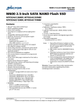
The Multi-Tech Systems MultiFRAD™ 100-Series, Model number FR111, is a
one-port Frame Relay Access Device (FRAD) with 56K DSU that
encapsulates non-packetized data from a serial device into frame relay
frames and is responsible for framing that data with header and trailer
information prior to transmission to a frame relay network. The MultiFRAD allows a non-frame relay device to connect to a common carrier
frame relay network service or private frame relay network. The access
device is designed with an internal 56K Data Service Unit (DSU) that
allows a single frame relay permanent virtual circuit (PVC) to be
connected to a 56K DDS circuit. On the receiving end of the communication link, the MultiFRAD serves to strip away the frame relay control
information in order that the target device is presented with the data
packaged in its original form.
The versatility of the MultiFRAD provides for a smooth integration with
existing equipment; e.g., multiplexers, routers, legacy equipment such
as cluster controllers, and asynchronous devices such as PCs running
remote control software. The non-frame relay device connects to the
data port on the back of the MultiFRAD and is capable of synchronous
data transmission up to 56K bps or asynchronous data transmission up
to 57.6K bps. The network connection is provided by the trunk port
which directly connects to the frame relay network.
Figure 1-1. MultiFRAD 100-Series
9
1.2
About This Manual
This manual describes the MultiFRAD, and tells you how to install and
configure the unit. The information contained in each chapter is as
follows:
Chapter 1 - Introduction and Description
Chapter 1 introduces the MultiFRAD 100-Series. A typical application
is presented with a discussion on ordering a frame relay line and how to
configure a MultiFRAD. A list of relevant specifications are provided at
the end of the chapter.
Chapter 2 - Front and Back Panel Descriptions
Chapter 2 describes the front panel indicators and back panel connectors. The front panel contains the LEDs for the data and trunk status.
The back panel provides cable connections to the data port, trunk port,
and a power connection for an external power supply.
Chapter 3 - Setup
Chapter 3 provides unpacking instructions, a setup procedure for
connecting cables and direction as to when you should configure the
unit. Also, after the unit is configured and if a V.35 interface is needed
for the data device, a procedure for changing the shunt to the V.35
position is provided.
Chapter 4 - Software Loading and Configuration
This chapter provides procedures on how to load the software utility and
configure the unit when a pc with a Windows application is connected to
the MultiFRAD. If a dumb terminal is connected to the MultiFRAD, the
unit can still be configured using the ASCII terminal menu system that is
present in the memory of the unit.
Chapter 5 - Software Utility Descriptions
This chapter provides a complete description of the Windows based
software used on the MultiFRAD 100-Series. From an icon in the
MultiFRAD program group, the Main menu is displayed. From the Main
menu, the data Port and trunk can be configured. Trunk statistics,
diagnostics, and the download feature are also described.
10
Chapter 6 - ASCII Terminal Menu System
Chapter 6 provides a description of the ASCII terminal menu system.
The ASCII terminal menu system is used when a dumb terminal is
connected to the data port. These menus allow you to configure the
data port and trunk, view statistics, reset the unit, and enable diagnostics.
Chapter 7 - Service, Warranty and Tech Support
Chapter 5 provides instructions on getting service for your MultiFRAD at
the factory, a statement of the limited warranty, information about our
user bulletin board service, and space for recording information about
your MultiFRAD prior to calling Multi-Tech's Technical Support. The final
three sections explain how to use our bulletin board service (BBS), and
get support through CompuServe and the Internet.
11
1.3
A Typical Application
A typical application for a MultiFRAD 100-Series is connecting a single
non-frame relay device to a frame relay network. The MultiFRAD 100Series is usually used at a remote site where a single DLCI and a single
device needs to be connected to a frame relay network. A MultiFRAD
100-Series can connect any existing synchronous or asynchronous
non-frame relay device to a frame relay network.
MultiMux
Data
Trunk
LAN 1
Ethernet Network
Command Modem
CD
RCV
XMT
OH
Channel Five
DTR
External Composite Link
CD
RCV
XMT
CTS
V.35
RCV
XMT
Channel one
RCV
XMT
Channel Six
RCV
XMT
Channel Two
RCV
XMT
Channel Seven
RCV
XMT
R
E
T
R
A
N
S
M
IT
Channel Eight
RCV
RCV
XMT
RCV
BUFFER
FULLNESS
LEVEL
1
2
3
F
L
O
C
T
R
L
R
C
V
L
I
N
K
A
L
A
R
M
R
E
M
O
T
E
D
W
N
T
E
S
T
A
S
Y
N
C
M
O
D
E
L
I
N
K
INTERNAL LINK DEVICE
(Modems)
M
5
V
M
6
2
H
K
9
2
/
D
V
8
S
3
3
U
3
4
XMT
MultiTech
Systems
MultiMux
Internal Composite Link
Channel Three Channel Four
Statistical Multiplexer
XMT
MMH2834
DSU
V29/V33 Modem
CD RCV XMT CTS 28.8 24.0 19.2 14.4 OH TR
CD RCV XMT CTS 56 19.2 RTS NS OOS TM
CD RCV XMT CTS
EC DBUP
Ethernet
Command Modem
CD
RCV
XMT
OH
DTR
External Composite Link
CD
RCV
XMT
CTS
V.35
Channel Five
RCV
XMT
Channel one
RCV
XMT
Channel Six
RCV
XMT
Channel Two
RCV
XMT
Channel Seven
RCV
XMT
R
E
T
R
A
N
S
M
IT
Channel Eight
RCV
BUFFER
FULLNESS
LEVEL
1
2
RCV
XMT
RCV
3
F
L
O
C
T
R
L
R
C
V
L
I
N
K
A
L
A
R
M
R
E
M
O
T
E
D
W
N
T
E
S
T
A
S
Y
N
C
M
O
D
E
L
I
N
K
INTERNAL LINK DEVICE
(Modems)
M
5
V
M
6
2
H
K
9
2
/
D
8
V
S
3
3
U
3
4
XMT
MultiTech
Systems
Channel 2
MultiMux
Internal Composite Link
Channel Three Channel Four
16
Frame Relay
17 Network
Statistical Multiplexer
XMT
MMH2834
DSU
V29/V33 Modem
CD RCV XMT CTS 28.8 24.0 19.2 14.4 OH TR
CD RCV XMT CTS 56 19.2 RTS NS OOS TM
CD RCV XMT CTS
EC DBUP
MultiMux
Trunk
Channel 1
26
MultiFRAD 100
Remote Site 2
27
T1 DSU
®
ech
TSystems
PC
Trunk
Data
MultiFRAD II
Host Site
PC
MultiFRAD 100
Remote Site 1
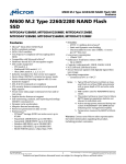
Figure 1-2. Typical Frame Relay Network
A MultiFRAD is easily connected to a frame relay network. One Data
Link Connection Identifier (DLCI) is required and it is provided by your
local network service provider when you request (subscribe) for a local
telephone line connection. When your local network service provider
engineers your connection, a virtual circuit is established between your
location and the destination of your connection. This virtual circuit is
called a permanent virtual circuit (PVC).
1.3.1 Ordering a Frame Relay Line
Ordering frame relay services from your local telephone company
involves connecting the physical line, defining the port connection,
configuring the PVC through the network, and assigning the Data Link
Connection Identifier (DLCI). The DLCI is a number between 16 and
1007 that identifies the PVC between your MultiFRAD and the phone
company's switch. The DLCI is assigned at the same time your local
service provider defines the permanent virtual circuit (PVC) that is the
path to your destination. When a PVC is assigned, an average guaranteed throughput is negotiated with the service provider. The guaranteed
throughput is called committed information rate (CIR) and is based on
12
your capability to present data to the local telephone switch. Your
capability to present data is determined by the internal DSU (Data
Service Unit) that can transfer digital data at a maximum rate of 56,000
bits-per-second to the network. A general rule of thumb in this scenario
is to assign a CIR of 32K bps and an excess burst rate (Be) of 24K bps.
The sum of the CIR and Be can not exceed your capability to present
data to the network. Finally during subscription, the management type
is defined by the local frame relay service provider. The management
type is a mechanism for communicating the status of the PVC and is
dependent upon which type is running on the telephone switch. Three
types of management are supported by the MultiFRAD: local management interface (LMI), Annex A, and Annex D.
1.3.2 How to Configure a MultiFRAD
Configuring a MultiFRAD is a simple process of defining the data port
device and the trunk parameters for frame relay. To configure a MultiFRAD, a pc has to be connected to the Data port on the MultiFRAD and
the MultiFRAD software loaded. To define the data port, the type of
device that is connected to it has to be defined. If the device is a
synchronous device such as a multiplexer, then the clocking and speed
of the device have to be defined in the Data Port Configuration dialog
box. A couple of other parameters also have to be set in order for the
multiplexer to communicate with the MultiFRAD.
If the data device is an asynchronous device, the Asynchronous Mode
option button changes the dialog box to display the asynchronous
parameters. The async parameters are the normal baud rate, word
13
length, parity, stop bits, and flow control. The Async Data Port Configuration dialog box displays the default parameters that may apply to a
majority async devices.
When the data device is defined, then the trunk configuration needs to
be defined. The trunk configuration is displayed in the Trunk Configuration dialog box. Most of the trunk information is supplied by your
network service provider.
For example, if the MultiFRAD at remote site 2 in our typical Frame
Relay network in Figure 1-2 is being configured, the DLCI is 26, the
Access Rate is 56000, and generally a Committed Info Rate of 32000
with a Excess Burst Rate (Be) of 24000 would allow the multiplexer at
remote site 2 to communicate with the host site. These parameters can
be added to the Trunk Configuration dialog box with a Management
Type defined by your network service provider, lets say for this example
that it is LMI. The default Management Parameters in the Trunk Configuration dialog box for the most part should work for this typical applica14
tion. The trunk configuration would be complete by clicking on the Save
button and returning to the Main menu. In the Main menu, click on the
download button to transfer the configuration to the MultiFRAD. Within a
few seconds the new configuration is downloaded to the MultiFRAD and
it is ready for operation.
15
1.4 FCC Regulations for Telephone Line Interconnection
1. This equipment complies with Part 68 of the FCC rules. On the
outside surface of this equipment is a label that contains, among other
information, the FCC registration number and ringer equivalence
number (REN). If requested, this information must be provided to the
telephone company.
2. As indicated below the suitable jack (USOC connecting arrangement) for this equipment is shown. If applicable, the facility interface codes
(FIC) and service order codes (SOC) are shown.
3. The ringer equivalence number (REN) is used to determine the
quantity of devices which may be connected to the telephone line.
Excessive RENs on the telephone line may result in the devices not
ringing in response to an incoming call. In most, but not all areas, the
sum of the RENs should not exceed five (5.0). To be certain of the
number of devices that may be connected to the line, as determined by
the total RENs, contact the telephone company to determine the
maximum REN for the calling area.
4. If this equipment causes harm to the telephone network, the telephone company will notify you in advance. But if advance notice isn’t
practical, the telephone company will notify the customer as soon as
possible. Also, you will be advised of your right to file a complaint with
the FCC if you believe it is necessary.
5. The telephone company may make changes in its facilities, equipment, operations, or procedures that could affect the operation of the
equipment. If this happens, the telephone company will provide advance notice in order for you to make necessary modifications in order
to maintain uninterrupted service.
6. If trouble is experienced with this equipment (the model of which is
indicated below) please contact Multi-Tech Systems, Inc. at the address
shown below for details of how to have repairs made. If the trouble is
causing harm to the telephone network, the telephone company may
request you remove the equipment from the network until the problem is
resolved.
7. No repairs are to be made by you. Repairs are to be made only by
Multi-Tech Systems or its licensees. Unauthorized repairs void registration and warranty.
8. This equipment cannot be used on public coin service provided by
the telephone company. Connection to Party Line Service is subject to
state tariffs. (Contact the state public utility commission, public service
16
commission or corporation commission for information.)
9. If so required, this equipment is hearing aid compatible.
Manufacturer:
Multi-Tech Systems, Inc.
Model Number:
MultiFRAD 100-Series
FCC Registration Number:
AU7USA-24704-XD-N
Ringer Equivalence:
N/A
Modular Jack (USOC)
RJ48
Service Center in U.S.A.
Multi-Tech Systems Inc.
2205 Woodale Drive
Mounds View, MN 55112 USA
(612) 785-3500 or (800) 328-9717
U.S. Fax (612) 785-9874
17
1.5
Canadian Limitations Notice
Notice: The ringer equivalence number (REN) assigned to each
terminal device provides an indication of the maximum number of
terminals allowed to be connected to a telephone interface. The
termination of a interface may consist of any combination of devices
subject only to the requirement that the sum of the ringer equivalence
numbers of all the devices does not exceed 5.
Notice: The Industry Canada label identifies certificated equipment. This
certification means that the equipment meets certain telecommunications network protective, operational and safety requirements. The
Industry Canada does not guarantee the equipment will operate to the
user’s satisfaction.
Before installing this equipment, users should ensure that it is permissible to be connected to the facilities of the local telecommunications
company. The equipment must also be installed using an acceptable
method of connection. The customer should be aware that compliance
with the above conditions may not prevent degradation of service in
some situations.
Repairs to certified equipment should be made by an authorized
Canadian maintenance facility designated by the supplier. Any repairs
or alterations made by the user to this equipment, or equipment
malfunctions, may give the telecommunications company cause to
request the user to disconnect the equipment.
Users should ensure for their own protection that the electrical ground
connections of the power utility, telephone lines and internal metallic
water pipe system, if present, are connected together. This precaution
may be particularly important in rural areas.
Caution: Users should not attempt to make such connections themselves, but should contact the appropriate electric inspection authority,
or electrician, as appropriate.
18
1.6
Specifications
Data Port
• Single data port with synchronous or asynchronous data format
• Async data rate up to 57.6K bps or sync data rate up to 56K bps
• RS232C and ITU-T V.35 interface using an adapter cable
• Internal shunt plugs to configure RS232C or ITU-T V.35 interface
• Async data format of 5,6,7, or 8 bits; 1, 1½, or 2 stop bits; odd,
even, or no parity
• Sync data format is HDLC/SDLC
• Data port connector is a DB-25 female
Trunk
• Single trunk port with synchronous DDS or compatible data format
• Sync data rate of 56k bps
• DDS interface with an RJ-48 keyed jack
• Full duplex over LADS (Local Area Data Set) or two-pair nonloaded metallic wire
Electrical/Physical/Environmental
• Voltage - 115v AC, 50/60 Hz
• Power - 2 watts
• Dimensions - 4.3" W x 1" H x 5.6" L
- 10.8 cm x 2.5 cm x 14.2 cm
• Weight - 8 oz. (224 g)
• Temperature - 32° to 120° F (0° to 50° C)
• Humidity - 20 - 90% non-condensing
Compatibility
• Link management via ANSI T1.617 Annex D, ITU-T Q.933 Annex A
or LMI
19
20
2
Front and Back
Panel Descriptions
21
22
2.1
Introduction
This chapter describes the front panel LEDs and back panel connectors.
The front panel has one row of LEDs for both the data channel and
trunk status. Two back panel connectors provide the data and trunk
connections. A circular power connector is provided to connect the
external power supply.
2.2
Front Panel
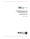
The front panel contains two sets of LEDs that provide the status of the
data and trunk connections. The data LEDs display the activity of the
data port, if V.35 interface signaling is used, and whether command
mode is active. The trunk LEDs display status whether the trunk is
transmitting or receiving frames, link status, and congestion.
Figure 2-1. Front Panel
Data
35
Lights when the data port is configured for a V.35
interface. That is, the data shunt is in the V.35 position.
CM
Command Mode (CM) LED lights when the Data/
Command mode switch is in the Command mode
position and blinks when the unit is in test mode.
TD
Transmit Data (TD) LED blinks when data is being
transmitted - on for a space and off for a mark.
RD
Receive Data (RD) LED blinks when data is being
received - on for a space and off for a mark.
TD
Transmit Data (TD) LED blinks when data is being
transmitted - on for a space and off for a mark.
RD
Receive Data (RD) LED blinks when data is being
DSU
23
received - on for a space and off for a mark.
DSU
Data Service Unit (DSU) LED lights when the unit is in
the DSU-only mode.
NS
The No Signal (NS) LED lights when no signal is
received from the network or when the signal is too
weak for normal operation.
OOS
The Out Of Service (OOS) LED lights when an outage
condition occurs. This happens when there is a failure
in the digital service that is detected by the network
and the telco sends a repetitive OOS sequence.
CD
The Carrier Detect (CD) LED lights when a carrier
signal is received from the network.
CN
Congestion (CN) LED lights when congestion is
detected on the trunk.
LK
Link (LK) LED blinks slowly when there is no link
management connection with the network. Blinks
quickly when link management is established with the
network. Remains solid ON when the network
indicates the PVC is active.
CD
Carrier Detect (CD) LED lights when a carrier signal is
detected from the network.
TD
Transmit Data (TD) LED blinks when data is being
transmitted - on for a space and off for a mark.
RD
Receive Data (RD) LED blinks when data is being
received - on for a space and off for a mark.
Trunk
24
2.3
Back Panel
The cable connections for the MultiFRAD are made at the back panel.
Two cable connections are provided and one power supply connection.
The Data connector allows the MultiFRAD to be connected to a nonframe relay device and the Trunk connector connects to a common
carrier frame relay network service or private frame relay networks. The
cable connections are shown in Figure 2-2 and defined in the following
sections.
Power
Data
Trunk
Figure 2-2. Back Panel
Power Connector
The Power connector is used to connect the external wall type transformer power supply to the MultiFRAD. The wall transformer plugs
directly into an AC outlet.
Trunk Connector
The Trunk connector is used to connect the MultiFRAD to a 56K DDS
circuit that provides the local access to the frame relay service. This
connector is a RJ48-keyed jack on the back panel of the unit.
Data Connector
The Data connector is used to connect the MultiFRAD to a non-frame
relay device, such as, multiplexers, routers, or legacy equipment such
as cluster controllers, or an asynchronous device such as a PC running
remote control software. A second use of this connector is to configure
the MultiFRAD. The Data connector is a DB-25 female connector
located on the back panel of the MultiFRAD.
The Data connector interface can be either an RS-232C or V.35 interface. When the V.35 interface is used, the data shunt has to be moved
from the default RS232 position to the V.35 position. Refer to "Shunt" in
this chapter for changing the data shunt. Refer to Appendix A for
cabling requirements in V.35 mode.
25
2.4
Switch Settings
The 8-position DIP switch located on the right side of the MultiFRAD
only uses the first four positions. The DIP switches are shown in Figure
2-3 and their settings are described in Table 2-1.
DIP-Switches
Figure 2-3. Switch Settings
Table 2-1. Switch Settings
Switch
1
Mode
Cmd/Data
Position
UP*
DOWN
2
Clocking
3
Loopback
4
DSU
UP*
5-8
Not Used
26
Data
Command
DDS
DOWN
Internal
UP*
Normal
DOWN
*Factory default setting
Description
Loopback
UP
FRAD
DOWN*
DSU
2.5
Shunts
V.35 signal levels are generally more reliable for high speed data and/
or longer cable distances. EIA-232D signal levels are intended for data
rates of 19,200 bps or less and cable lengths of 50 feet or less. For
higher speeds and/or longer distances, V.35 is generally preferred.
There are two shunt positions on the printed circuit board that configure
the data port for either RS232 or V.35 interface. Both DIP sockets for the
shunts are shown in Figure 2-4.
V.35 Shunt Position
RS232 Shunt Position
Figure 2-4. Shunts
In Figure 2-3, the shunt is shown in the RS232 (default) position (i.e., in
the right-hand DIP socket - the one closest to the DIP switches. To
change the location of the shunt, refer to the V.35 Shunt procedure in
Chapter 3.
27
28
3
Setup
30
3.1
Introduction
This chapter describes the unpacking of the MultiFRAD, cable connections depending on whether EIA-232D or ITU-T V.35 interface signaling
is used on the data port, and how to configure the unit dependent on
your site situation. Once the MultiFRAD is configured, then the data port
can be connected to your data port device.
3.2
Unpacking
The shipping box contains the MultiFRAD, power adapter, and your
owner's manual. Inspect the contents for signs of any shipping damage.
If damage is observed, do not power up the unit, contact Multi-Tech's
Technical Support for advice (refer to Chapter 7 - Warranty). If no
damage is observed, place the MultiFRAD in its final location and verify
the signal levels (EIA-232D or ITU-T V.35) for the data port, and connect
your cables, phone lines, and power supply.
3.3
Safety Warnings
1. Never install telephone wiring during a lightning storm.
2. Never install telephone jacks in wet locations unless the jack is
specifically designed for wet locations.
3. Never touch uninsulated telephone wires or terminals unless the
telephone line has been disconnected at the network interface.
4.
Use caution when installing or modifying telephone lines.
5. Avoid using a telephone (other than a cordless type) during an
electrical storm. There may be a remote risk of electrical shock
from lightning.
6. Do not use the telephone to report a gas leak in the vicinity of the
leak.
31
3.4
Setup
Use the following steps to setup your MultiFRAD. If V.35 electrical
interface signaling is required on the data port, but a pc with EIA-232D
signaling is being used to configure the MultiFRAD, the unit has to be
configured before you change to V.35 signaling. Perform the following
procedure to connect your cables, configure the unit, and then change
to V.35 signaling on the data port.
1. Ensure that the DIP-Switch settings on the side of the unit are set
for a command mode of operation. Refer to the Switch Settings in
Chapter 2.
DIP-Switches
Figure 3-1. DIP-Switch Settings
2. Connect the external wall transformer power supply to the MultiFRAD and plug it into a live AC outlet. The MultiFRAD does not
have a power switch. When power is applied to the unit, the front
panel LEDs will light.
Power
Data
Trunk
Figure 3-2. Power Connection
3. Connect a pc running Windows® to the Data connector on the
back of the MultiFRAD. Use an appropriate EIA-232D cable.
Refer to Appendix A for EIA-232D cable details.
Power
Data
Trunk
PC Serial Cable
Figure 3-3. Data Connection
32
4. Connect an RJ48 phone cable to the Trunk connector on the back
of the MultiFRAD. Connect the other end of the phone cable to the
local access line jack.
Power
Data
Trunk
Figure 3-4. Trunk Connection
5. The MultiFRAD can be configured in two ways: If a pc running a
Windows software is being used to configure the unit, refer to the
Software Loading procedure in Chapter 4.
If a terminal running a communications software is being used to
configure the unit, refer to Configuring your MultiFRAD using a
dumb terminal in Chapter 5.
6. Once the MultiFRAD is configured for your application, you can
disconnect the pc and connect your data port device. If the data
port device contains an EIA-232D interface, the same serial cable
can be used. If the data port device contains a V.35 interface, the
data port shunt must be moved to the V.35 position and a V.35
adapter cable must be connected to the data port connector. Refer
to Section 3.5 for procedures on moving the shunt to the V.35
position. Refer to Appendix A for cable details.
7. Place the Command Mode switch (Switch 1) on the side of the
MultiFRAD in the UP position for the data mode operation.
33
3.5
V.35 Shunt
Either EIA-232D or ITU-T V.35 electrical signal interface can be selected
on the data port. Units are shipped with EIA-232D signal levels selected. Use the following procedure to select V.35.
CAUTION
This procedure requires opening the unit. Like most
products of this type, this product contains components
that are sensitive to static and static discharge. Please
use your best efforts to avoid static discharge when
contacting the components inside this unit.
WARNING:
Always disconnect the power cord before opening
the enclosure to avoid any chance of electric shock.
1. Unplug the power cord.
2. The enclosure consists of two halves. Using a Phillips screwdriver,
remove the two screws from the bottom of the unit. Remove the
top half.
3. Pry the data port shunt out of its RS232 socket and insert it into the
V.35 socket.
V.35 Shunt Position
RS232 Shunt Position
Figure 3-5. Shunts
4. Carefully reassemble the unit, making sure that no foreign objects
are accidentally left inside.
6. The data port is now configured with V.35 signal levels. The cable
pin designations are shown in Appendix A. To connect to a device
equipped with a V.35 34-pin connector, you must obtain an
adapter cable. Using the signal pin designations in Appendix A,
you may make or order a cable from most any cable vendor.
34
4
Software Loading
and Configuration
35
36
4.1
Introduction
This chapter covers the loading of the software utility and then the
configuration of the unit from either a Windows based pc or a dumb
terminal. When a Windows based pc is used, the software utility is
loaded using the procedures in section 4.2 and then the unit is configured using the procedures in section 4.3. If a dumb terminal is used, the
MulitFRAD 100 can be configured using the ASCII terminal menu
system present in memory of the unit.
4.2
Loading Software
1
Turn on your PC connected to the Data Port of your MultiFRAD
and run Windows®.
2
Create a backup copy of your MultiFRAD software diskette before
you install the software. Store the master diskette in a safe place
and install the MultiFRAD software using the backup copy.
3
Insert the backup disk for the MultiFRAD into the floppy drive.
4
Click on the File Menu in your Program Manager.
5
Click on Run. The Run dialog box is displayed.
6
Type a:\install or b:\install (depending on the location of your
floppy disk drive) in the Command Line field, and then click on
OK.
7
The MultiFRAD 100 - Select Directories dialog box is displayed.
If you are installing the software from drive A and your Destination Directory is the default directory, click on OK to continue
8
The Installing MultiFRAD dialog box is displayed.
37
Click on Install to continue installation, at any time you may click
on Abort if you wish to cancel the install immediately.
9
The Expanding/Copying Files From: dialog box is displayed. You
can view the progress of the installation from this dialog box. You
can click on Abort at any time to cancel the install.
11 The MultiFRAD 100 Installation dialog box asks "Please select a
communication port for the setup utility to use" dialog box is
displayed. In other words, select which COM port on your PC that
is connected to the Command Port of the MultiFRAD.
38
Select the COM port (COM1,COM2,COM3, or COM4) for the setup
utility. The default port is COM1. Click on OK when you are
satisfied with your selection.
12 When the setup installation is successful, a system message is
displayed stating "MultiFRAD 100 Installation Successful. Click
on OK to continue.
13 Your are returned to the Program Manager where the MultiFRAD
program group and icons are created.
This completes the software loading. Now, proceed to configuring your MultiFRAD.
39
4.3
Configuring Your MultiFRAD using Windows
Configuration of your MultiFRAD using Windows starts after the software is loaded and program group is displayed in the Program Manager.
1
Double click on the MultiFRAD 100 Configuration icon.
2
When the MultiFRAD 100 dialog box is displayed, click on the
Data Port button to display the Data Port Configuration dialog
box.
3
The Data Port Configuration dialog box is displayed with the
Mode set to Asynchronous. If your data device is an Asynchronous device, refer to the User documentation to set the async
parameters that meet the conditions of your installation.
40
If your data device is a synchronous device, click on the Synchronous option button and the parameters for the synchronous
mode are displayed. Refer to the User documentation to set the
sync parameters that meet the conditions of your installation.
4
When you are satisfied with your selections, click on the Save
button to save your new parameters. Then click on the OK button
to return to the main menu.
5
From the Main menu, click on the Trunk button to display the
Trunk Configuration dialog box.
41
6
Click on the DLCI numeric dialog box. Enter the DLCI number
that was provided by your service provider at subscription time.
To change the DLCI, click on the DLCI numeric dialog box and
back space through the default number and then enter your DLCI.
7
Click on the Management type option button supported by your
Frame Relay network. The Management type is supplied by your
service provider at subscription time.
For most applications, the default Management Parameters
should be adequate.
Polling Interval is the number of seconds for a polling cycle (i.e.,
the time period between each status enquiry message sent from
the MultiFRAD).
Full Status Counter displays a number between 1 and 255 that is
the number of polling cycles (minus one) before a full status is
requested from the network.
Error Threshold displays a number between 1 and 10 that is less
than or equal to the Monitored Event count.
Monitored Event displays a number that is between 1 and 10 that
is greater than or equal to the Error Threshold.
8
Click on the Committed Info Rate numeric box and enter the CIR
value provided by your service provider at subscription time.
9
Click on the Excess Burst Rate (Be) numeric box and enter the
Be value provided by your service provider at subscription time.
10 The Back to Back check box should normally remain unchecked.
11 Click on the Encapsulation Type you need. Mux Mode encapsulation can be used only if the FRAD at the other end of the PVC is
42
another MultiFRAD 100. Raw Mode encapsulation can be used
for any type of FRAD at the other end.
12 Click on the OK button to return to the Main menu.
13 Click on the Download button to write the new configuration to
the MultiFRAD.
14 The Configuration dialog box is displayed.
The Configuration downloaded successfully. Reset the unit for
configuration to take effect and put dip switch number 1 in the up
position. Click on OK to proceed.
15 You are returned to your Program Manager where the MultiFRAD
100 Program Group and Program Item (the Windows icons) have
been created.
Your MultiFRAD 100 is fully operational at this time.
43
4.4
Configuring your MultiFRAD using a Dumb
Terminal
To configure your MultiFRAD, power up a terminal or pc running
communications software and hit the ENTER key. The Main menu
appears on your screen, configure the data port for sync or async mode
of operation and the trunk for the frame relay parameters. The MultiFRAD configuration is contained in the following procedure.
1
Apply power to your terminal or pc. After the terminal or pc boots
up, run the communications software. Setup your communications software for a speed between 2400 and 115.2K bps, 8-bits,
no parity, and 1-stop bit. Press the ENTER key to display the
MultiFRAD Main Menu.
2
Enter option 1 and press the ENTER key to display the Configuration menu.
Configurations
1 - Data Port Configuration
2 - Trunk Configuration
3 - Factory Default Configuration Options
S - Store All Configurations
M - Main Menu
P - Previous Menu
Selection: _
3
If your Data port is being setup for Async mode of operation,
proceed to step 4 to configure your data port.
If your Data port is being setup for a sync mode of operation,
enter option 1 in the Configuration menu and press ENTER. Enter
1 again and the Data Port Async/Sync submenu is displayed.
Enter option 2 for Sync mode of operation. Then proceed to step
5 to configure your data port.
44
4
If the data port is being setup for Async mode of operation and a
port speed of 57.6K, initially the data port does not have to be
changed, proceed to step 6 to configuring the Trunk.
Data Port Configuration
1
2
3
4
5
6
7
8
9
10
11
S
M
P
-
Async/Sync:
Speed:
Word Length:
Stop Bits:
Parity:
Flow Control:
Enq/Ack Flow Control:
Echo:
Pacing:
EIA Pass Through:
Pass Xon:
Store All Configurations
Main Menu
Previous Menu
Async
57600
8
1
None
CTS
Off
Off
Off
Off
Off
Selection : _
If the data port configuration needs to be changed, enter the
option number to be changed and a submenu is displayed.
Change the option to meet the conditions of your installation.
When the data port is configured to meet your site requirements,
proceed to step 6 to configure the Trunk.
5
Change the Sync Data Port Configuration to meet the conditions
of your installation by selecting the option needing change and a
submenu is displayed with your selections.
Data Port Configuration
1 - Async/Sync:
2 - Speed:
3 - Idle Condition:
4 - NRZ/NRZI Encoding:
5 - CRC Preset:
6 - Inter-frame Timer:
S - Store All Configurations
M - Main Menu
P - Previous Menu
Selection : _
Sync
57600
Flags
NRZ
All 1s
Off
When the Sync Data Port is configured to meet your site requirements, enter the letter S and press ENTER to store all configurations. Then enter the letter P and press ENTER to return to the
Configuration menu.
45
6
From the Configuration menu, enter 2 and press ENTER. The
Trunk Configuration menu is displayed.
Trunk Configuration
1 - Access rate:
2 - RTS Signal Status:
3 - Back to Back:
4 - DLCI:
5 - Committed Info Rate(CIR):
6 - Excess Burst Rate (Be):
7 - M a n a g e m e n t t y p e:
8 - Polling Interval:
9 - F u l l St a t u s C o u n t e r :
10- Error Threshold:
11 - M o n i t o r e d E v e n t C o u n t :
12- Encapsulation Mode:
S - St o r e A l l C o n f i g u r a t i o n s
M - Main Menu
P - Previous Menu
56000
Follows input from DTE
Off
16
32K
24K
Annex A
10Sec
6
3
4
Mux
Selection : _
In the Trunk Configuration menu, the Access rate option (1)
displays the data rate of the trunk. This rate can not be changed.
Option 2 should remain in the default condition (Follows input pin
from DTE) when used in a frame relay network. Option 3, the
Back to Back option should normally remain off. Options 4 thru 6
are supplied by your service provider at the time the trunk was
provisioned. These values have to be the same as the provisioned values. Options 8 thru 11 modify the management
protocol and for the most part should remain unchanged. Option
12 Encapsulation Mode depends on the type of device at the
other end of the frame relay network. If a MultiFRAD is at the
other end of the network, then the Mux mode needs to be
selected. If a non-MultiFRAD 100 is at the other end of the
network, then Raw mode needs to be selected.
7
To enter the DLCI for your trunk, enter 4 and press ENTER. A DLCI
submenu is displayed.
Enter the DLCI(Data Link Connection Identifier).
Valid values are between 0016 to 1007.
x
P
- Enter Number, or
- Previous Menu
Selection : _
46
Enter the number that corresponds to the DLCI for your trunk. A
two-digit number can be entered and the zeros will proceed the
digits. The DLCI is supplied by your network service provider at
the time the trunk was provisioned.
When you have entered your DLCI, the Trunk Configuration menu
is displayed.
8
From the Trunk Configuration menu, enter option 5 Committed
Info Rate (CIR) and the CIR menu is displayed.
Enter the CIR (Committed Information Rate), in
units of 1000 (1K). Valid values are between 0K
and 128K. The CIR should be equal to or less
than the Trunk access rate.
x
P
- Enter Number, or
- Previous Menu
Selection : _
Enter the number that corresponds to the CIR in units of 1K for
your trunk. The CIR range is from 0 to 128K and should be equal
to or less than the trunk access rate which can not exceed 56K.
The CIR is supplied by your network service provider at the time
the trunk was provisioned.
When you have entered your CIR, the Trunk Configuration menu
is displayed.
9
From the Trunk Configuration menu, enter option 6 Excess Burst
Rate (Be) and the Be menu is displayed.
Enter the Be (excess Burst Rate), in units of 1000
(1K). Valid values are between 0K and 128K. The
sum of Be + CIR should be equal to or less than
the Trunk access rate.
x
P
- Enter Number, or
- Previous Menu
Selection : _
Enter the number that corresponds to the Be in units of 1K for
your trunk. The Be range is from 0 to 128K and the sum of Be
plus CIR should be equal to or less than the trunk access rate.
47
The Be is supplied by your network service provider at the time
the trunk was provisioned.
When you have entered your Be, the Trunk Configuration menu is
displayed.
10 From the Trunk Configuration menu, enter option 7 Management
Type and the Management Type menu is displayed.
Management Type
1
2
3
P
-
Annex D (ANSI T1.617)
LMI
Annex A (ITU-T Q.933)
Previous Menu
Selection : _
Enter the number that corresponds to the Management Type for
your trunk. The Management Type is supplied by your network
service provider at the time the trunk was provisioned.
Options 8 thru 11 modify the management protocol between the
MultiFRAD and the network switch. For most applications, the
default values should be adequate. If you do not need to change
any of them, proceed to step 15.
11 From the Trunk Configuration menu, enter option 8 Polling
Interval and the Polling Interval menu is displayed.
Enter the Polling Interval, in units of seconds.
Valid values are between 5 and 30 seconds.
x
P
- Enter Number, or
- Previous Menu
Selection : _
Enter the number of seconds for a polling cycle (i.e., the time
period between each status enquiry message sent from the
MultiFRAD).
12 From the Trunk Configuration menu, enter option 9 Full Status
Counter and the Full Status Counter menu is displayed.
48
Enter the Full Status Counter.
Valid values are between 1 and 255.
x
P
- Enter Number, or
- Previous Menu
Selection : _
Enter the number between 1 and 255 that is going to be the
number of polling cycles (minus one) before a full status is
requested from the network.
13 From the Trunk Configuration menu, enter option 10 Error
Threshold and the Error Threshold menu is displayed.
Enter the Error Threshold.
Valid values are between 1 and 10. The Error
Threshold must be less than or equal to the
Monitored Event Counter.
x
P
- Enter Number, or
- Previous Menu
Selection : _
Enter a number that is less than or equal to the Monitored Event
Count.
14 From the Trunk Configuration menu, enter option 11 Monitored
Event Count and the Monitored Event Count menu is displayed.
Enter
Valid
Event
Error
x
P
the Monitored Event Count.
values are between 1 and 10. The Monitored
Count must be greater than or equal to the
Threshold.
- Enter Number, or
- Previous Menu
Selection : _
Enter a number between 1 and 10 that is greater than or equal to
the Error Threshold.
49
15 Enter the letter S and press ENTER to store all configurations.
Then enter the letter M and press ENTER to return to the Main
Menu. Enter 5 to Exit Command Mode.
16 Place the Command Mode switch (Switch 1) on the side of the
MultiFRAD in the UP position and return to step 6 in the Setup
procedure in Chapter 3.
5
Software Utility
Descriptions
52
5.1
Introduction
This chapter describes the MultiFRAD software which is designed for
the Microsoft® Windows® environment. The MultiFRAD 100 Program
Group has three icons that allow you to launch the software, download
a firmware update, and configure the console pc port in order to
communicate with the MultiFRAD.
The MultiFRAD 100 Configuration icon allows you to configure the data
port for either a synchronous or asynchronous device, configure the
trunk for a frame relay network, view statistics of the data port, perform
diagnostic test of the unit, and download a new configuration to the unit.
The Download Firmware allows new operating code (firmware) to be
transferred to the MultiFRAD. The Configuration Port Setup icon
establishes the parameters for which the console pc communicates with
the MultiFRAD.
You may also start the MultiFRAD 100 Configuration from the File
Manager by selecting the unofrad directory and double clicking on the
unofrad.exe program in the file list.
You may also run MultiFRAD 100 Configuration from either the Program
Manager or the File Manager by clicking on the Run command in the
File Menu, then typing: C:\unofrad\unofrad.exe in the Command Line
field.
5.2
MultiFRAD Main Menu
The MultiFRAD 100 Main menu organizes your configuration process
into the Data Port and Trunk configurations, allows you to view statistics,
initiate Diagnostics, download a new configuration, exit the application,
and view help screens.
The following sections describe each button in the main menu and each
field and button in each dialog box.
53
5.2.1 Configuration
Data Port
This button allows you configure the data port for either synchronous or
asynchronous mode of operation.
Trunk
This button lets you define the frame relay parameters.
5.2.2 Others
Statistics
This button allows you to view statistics of the trunk port.
Diagnostics
This button allows you to run two loopback tests, a memory test, and watch
dog test.
5.2.3 Download
You can update the MultiFRAD setup on the target. This will bring the
MultiFRAD down for updating the setup. Then, reboot the MultiFRAD.
5.2.4 Exit
This will end your MultiFRAD session and return you to the Program
Manager.
54
5.2.5 Help
A thorough On-line Help system is provided with abbreviated information on the dialog boxes and the buttons within a dialog box.
5.2.6 MultiFRAD Version
The current version number of the MultiFRAD firmware is displayed in
this field.
55
5.3
Data Port Configuration
This dialog box allows you to configure the data port. You will be able to
set the parameters required for the successful operation of the port.
Mode Asynchronous/Synchronous
This allows you to set synchronous or asynchronous parameters
required for transferring data between the MultiFRAD and the data port
device. The data port can operate either in Asynchronous (UART) mode
or Synchronous (HDLC) mode. Choose the Mode option that meets
your site requirements. Both data port modes are discussed in the
following sections.
Sync Mode Parameters
The following parameters are modifiable when the device connected to the
data port connector on the back of the MultiFRAD 100-Series is a synchronous device. To change a parameter, click on the option button to be
activated. To change a parameter using a drop down menu, click on the
drop down arrow and a drop down menu displays the new parameters.
Click on the desired parameter.
Speed
The Speed parameter needs to be set to match the speed of the sync device.
When the data port is connected to a synchronous device, the baud rate is
from 300 bps to 56K bps. The default port speed is 56K bps.
56
Note: The MultiFRAD always provides the clocking signal to the sync
device. The MultiFRAD 100's data port can not be set to external clocking,
it is always internal clocking.
Between Frames
The Between Frames parameter must be set to match the idle condition of
the synchronous device connected to the data port. The Between Frames
determine what happens when the synchronous data line is idle (i.e., no
data frames are being transmitted). The default condition is to continuously
send SDLC flags (Flags). The other condition is the mark state (Mark). The
transmit LED will be off during idle time if the synchronous device is in the
mark state during idle conditions.
Encoding Scheme
The Encoding Scheme parameter refers to the fact that synchronous data
can be encoded by using either NRZ (Non-Return to Zero) or NRZI (NonReturn to Zero Inverted) method. This parameter must match the synchronous device’s encoding. The default is NRZ. With NRZ encoding, the data
is represented normally. With NRZI encoding, a logical one is represented
by no transmission and a zero is represented by a transition at the beginning
of the bit. Most synchronous devices can be configured for either NRZ or
NRZI. If a synchronous device is not configurable, it most likely is set to NRZ.
Refer to the device’s user documentation for the encoding method.
InterFrame Timer (in mS)
The InterFrame Timer parameter can be changed to make the MultiFRAD
wait a specified length of time between frames. You can choose Off and
delay times of 2,5,10 and 15 milliseconds. A typical use for this parameter
is to simulate transmission delays encountered with equipment that toggles
hardware signals after transmission of each frame, like PC cards used to
connect to legacy systems. The following options can be specified for the
timer: Off, 2mS, 5mS, 10mS, and 15mS. The default is off.
57
CRC Preset
The CRC Preset parameter allows the user to specify whether the polynomial used to calculate the CRC for each frame is preset to all 1s or all 0s.
This option must match the synchronous device’s CRC-preset setting. The
default is All 1s.
Async Mode Parameters
Following Parameters are modifiable when the device connected to the
data connector on the back of the MultiFRAD 100-Series is an asynchronous device. To change a parameter using a drop down menu, click on the
drop down arrow and a drop down menu displays the new parameters.
Click on the desired parameter. To change an option parameter, click on
the option box. An "x" appears in the option box if the option is active.
Baud Rate
The Baud Rate parameter needs to be set to match the speed of the async
device. The baud rate ranges from 300 bps to 57.6K bps. The default port
speed is 19.2k bps.
Word Length
The Word Length parameter sets the number of bits in a word. The word
length range is 5 to 8 bits. The default is 8 bits.
58
Parity
The Parity parameter sets parity for odd, even or none. Under normal
conditions, parity is set to none. The default is none.
Stop Bits
The Stop Bits parameter sets the number of stop bits. The number of stop
bits can be 1, 1.5, or 2. The default is 1 bit.
Flow Control
The Flow Control parameter allows for two types of flow control: the
software-based XON/XOFF and the hardware-based Clear to Send (CTS).
The default is CTS. Flow control is the means by which data flow from the
device into the MultiFRAD is controlled. Flow control is necessary when the
data handling capacity of the data port cannot keep up with the volume of
data sent to it. When the data device controls data flow to itself, it is called
pacing (see Pacing). The combination of flow control from the port device
and pacing to the data device is how data transfers are regulated so that
no data is lost.
MultiFRAD-INITIATED
FLOW CONTROL
CHANNEL DEVICEINITIATED PACING
DATA
Channel
Device
DATA
MultiFRAD
Flow control stops the input
of data to the MultiFRAD
Channel
Device
MultiFRAD
Pacing stops the output of
data from the MultiFRAD
Pacing
The Pacing parameter controls the data flow to the data device. Pacing is
necessary when the flow of data to a device operating on the data port is
more than it can process. If the device cannot process the volume of data
sent to it, then the pacing option should be turned on. The pacing method
used is determined by the type of flow control. The default condition is for
this option to be turned off.
59
Pass Xon
The Pass Xon parameter enables the XON/XOFF flow control signals to be
passed on to the data device. This option has to be used in conjunction with
the software-based XON/XOFF flow control option. The default condition is
for this option to be turned off, and normally it should remain off.
Echo
The Echo parameter enables data entered on the data device keyboard to
be returned to the device's monitor. The purpose of this option is so that an
operator will not experience undue delays in seeing entered data appear
on their monitor. The default condition for the echo option is off.
EIA Pass Through
The EIA Pass Through parameter allows the data device to receive EIA
control signals through the MultiFRAD. Since, in normal interactive operation, the existence of a MultiFRAD should be transparent to the user, the
EIA pass through option allows a terminal to operate as if it were connected
directly to a communications line and not through a MultiFRAD. This is done
by allowing selected pins (signals) on one MultiFRAD to be passed through
to selected pins on a remote MultiFRAD. The default condition is for this
option to be turned off. The following diagram shows how the EIA pass
through option routes the selected signals:
MultiFRAD
B
MultiFRAD
A
8 OUT
IN 4
IN 20
Trunk Facility
OUT 8
OUT 6
60
6 OUT
4 IN
20 IN
ENQ/ACK
The Enq/Ack parameter is a special flow control protocol used in Hewlett
Packard computer systems. This option is sometimes referred to as
Enquire/Acknowledge flow control because it’s based on the computer
sending an enquiry (ENQ) and then expecting an acknowledgment (ACK).
61
5.4
Trunk Configuration
This dialog box allows you to configure the trunk. You will be able to set
the parameters required for the successful operation of the trunk.
Frame Relay is a multiplexing protocol designed to operate over
transmission facilities that are virtually error free. In Frame Relay,
frames are routed through the network on the basis of an attached label
called a Data Link Connection Identifier (DLCI). Frame Relay combines
the bandwidth efficiency of packet switching with end-to-end protocol
transparency, increased speed and performance.
Data Link Connection Identifier (DLCI)
The DLCI is the identification of a particular logical link in the Frame Relay
network and has local significance only. The DLCI is assigned by the frame
relay service provider for the PVC (Permanent Virtual Circuit) that is on your
access circuit. As the logical link traverses the Frame Relay network, input
DLCI will be mapped to an output DLCI at every node. Access DLCIs for
permanent logical links are assigned at subscription time. Trunk DLCIs are
allocated dynamically. The valid value for a DLCI ranges from 16 to 1007
with a default of 16.
Management Type
The Management Interface defines a set of procedures and messages to
manage a PVC and the physical link at the user network interface. Three
management types are used: Local Management Interface (LMI), Annex A,
or Annex D. The management type is determined by the network service
provider at subscription time.
62
LMI describes a protocol and associated procedures operating on the local
interface between the user and the network. It notifies the user of the
addition, deletion, and presence of the PVC in the network. It also notifies
the user of the end-to-end availability or unavailability of a PVC. Basic LMI
protocol is based on a synchronous polling scheme where the user polls
the network to obtain status information on the PVCs configured on the
interface. LMI simply augments the ANSI/CCITT standard Frame Relay
protocol and in no way interferes with the normal operation of user PVCs
on the interface.
Annex D provides additional procedures for permanent virtual connections
using unnumbered information frames. Annex D describes the means for
notification of outage of a permanent virtual connection and recovery from
such a condition. This follows the ANSI T1.617 standards.
Annex A provides additional procedures for permanent virtual connections
using unnumbered information frames. Annex A describes the means for
notification of outage of a permanent virtual connection and recovery from
such a condition. This follows the ITU-T Q.933 standard
Encapsulation Type
The Encapsulation Type depends on the type of device that is connected
at the other end of the trunk. If another MultiFRAD 100 is connected at the
other end of the trunk, then the Mux mode is used. If a non-MultiFRAD 100
is at the other end of the trunk, then the Raw mode is used.
Management Parameters
Polling Interval
The Polling Interval defines a time period in which a status enquiry message
is sent from the MultiFRAD to the network. The Status Enquiry message
requests the status of the PVC(s) or verification of the status of a physical
link. When the Status Enquiry message is sent by the MultiFRAD, the Polling
Interval is restarted. The network responds with a status message that
reports the status of the PVC or verifies the integrity of the physical link. The
polling interval is 5 to 30 seconds with a default of 10 seconds.
63
Full Status Counter
The Full Status Counter determines how may Polling Intervals take place
before a full status is requested from the network. A full status enquiry
message is sent from the MultiFRAD to the network requesting a status
report of the PVC on the physical link. The Full Status Counter can range
from 1 to 255, with a default of 6.
Error Threshold
The Error Threshold is used to indicate the threshold number of errors
occurring during a full cycle of the Monitored Event. After each full cycle of
the Monitored Event Counter, if the actual number of errors equals or
exceeds the error threshold, the trunk status is brought down and no data
may be sent. The error count is reset at the beginning of each cycle of the
Monitored Event Counter. The Error Threshold Count can range from 1 to
10 with a default of 3 and should be less than or equal to the Monitored Event
Counter.
Monitored Event
The Monitored Event determines the number of Polling Intervals that have
to take place before the User Network Interface is operational. It is also used
with the error threshold count to determine if the trunk should be brought
down. The range of this counter is from 1 to 10 events with a default of 4
events
Committed Info Rate (CIR)
The Committed Info Rate (CIR) determines the data transfer rate at which
the network is committed to handle under normal conditions. This rate is
the average over a minimum increment of time. The CIR may be less than
or equal to the Access Rate. When the CIR is exceeded, but the data rate
is below the Excess Burst Rate (Be), there is a possibility that data may be
discarded. When the Be is exceeded, data will most likely be discarded.
The default CIR is 32K.
64
Back to Back
The Back to Back is used to test the port by connecting two MultiFRADs
together without a frame relay network in between them. Back-to-back
mode still requires the use of DSU/CSUs, but they should not be connected
over the frame relay network. The options are On and Off with a default of
Off.
Back-to-back mode is useful when two MultiFRADs are at the same location
and they are connected via DSUs for testing. Back-to-back mode can also
be used to connect two MultiFRADs over a private leased line.
Excess Burst Rate (Be)
The Excess Burst Rate (Be) defines the maximum allowable data transfer
rate the MultiFRAD can exceed the Committed Info Rate (CIR) during a time
interval. The Be is the maximum additional data rate at which the MultiFRAD
can present to the network during a time interval. The default Be is 24K.
65
5.5
Statistics
This dialog box allows you to view status of the trunk. Its possible to
view signal status and other characteristics like data frames transmitted
or received, status of enquiries transmitted and messages received and
the status of the messages received.
If you want to clear the statistics so that you can have fresh statistics,
then you should click on the clear button.
5.6
Diagnostics
The MultiFRAD Diagnostics dialog box allows you to run two loopback
tests, a memory test, and watch dog test. The Diagnostics dialog box is
displayed by clicking on the Diagnostic button in the MultiFRAD dialog
box.
66
Loop Tests
The loop tests provide a short and long loop test. The short loop test is the
data port loopback test which loops back the data from the data port to the
sending device (DTE). The long loop test is the trunk loopback test which
again receives data from the DTE device and loops it back from the internal
DSU.
The data port loopback test has two modes which depend on the device
connected to the data port. If the data port device is an async device, then
the Command Mode switch (DIP-Switch position 1) can be in either position
in order for the data to be looped back to the sending (DTE) device. If the
data port device is a sync device, the Command Mode switch must be in the
up position (Data mode) in order for the device to receive the looped back
data.
The trunk loopback test requires that DIP-Switch position 3 (Loopback Test
Mode) be in the DOWN position in order for the internal DSU to loop back
the data received from the DTE device.
Other Tests
The memory test checks the on-board memory. A warning will be displayed
that "The unit will be reset now and the factory defaults will be restored.
The watch dog test will reset the unit. A "Warning: This watchdog test will
reset the unit. Do you wish to continue?" A brief message will be displayed
stating that the watch dog test passed.
67
6
ASCII Terminal
Menu System
70
6.1
Introduction
The menu system for the MultiFRAD provides a set of user-friendly
configuration menus that are accessible from a main menu. The Main
Menu contains five options that allow you to configure your MultiFRAD;
display statistics; reset the unit or data port; run diagnostic tests, and
exit the command mode.
To select one of the options from the Main Menu, enter the number
corresponding to the option and press ENTER. A submenu is displayed
that allows you to configure your MultiFRAD, display statistics, or run
one of many diagnostics tests.
6.2
Configurations Menu
From the Configurations menu you can configure the data port or trunk,
restore factory defaults; store all current configurations; or return to the
Main Menu.
Configurations
1 - Data Port Configuration
2 - Trunk Configuration
3 - Factory Default Configuration Options
S - Store All Configurations
M - Main Menu
P - Previous Menu
Selection: _
To configure the data port or trunk, enter the corresponding option
number and press ENTER. To change to factory defaults, enter number
3 and press enter. You can set factory defaults for the entire unit or for
either the data port or trunk. Select the option you wish to change, and
71
a message will appear on your screen saying to wait for 3 seconds.
Then press ENTER to return to the Main Menu. To store the current
configuration, enter S and press ENTER. To return to the Main Menu,
enter M and press ENTER.
6.2.1 Async Data Port Configuration
The Async Data Port Configuration menu allows you to configure the
data channel for either asynchronous or synchronous operation,
depending on the type of device connected to the data port. If the port is
configured for synchronous operation, refer to Sync Data Port Configuration.
When the port is configured for asynchronous operation, options such
as speed, flow control, and pacing may need to be changed. The
following Data Port Configuration menu displays the default parameters
for async mode of operation:
Data Port Configuration
1
2
3
4
5
6
7
8
9
10
11
S
M
P
-
Async/Sync:
Speed:
Word Length:
Stop Bits:
Parity:
Flow Control:
Enq/Ack Flow Control:
Echo:
Pacing:
EIA Pass Through:
Pass Xon:
Store All Configurations
Main Menu
Previous Menu
Async
57600
8
1
None
CTS
Off
Off
Off
Off
Off
Selection : _
The Async/Sync option configures the port for either asynchronous or
synchronous operation. When an asynchronous device such as a PC or
a host computer is connected to the port, the data port needs to be
configured for asynchronous operation. The default for this option is
Async.
The Speed option needs to be set to match the speed of the async
device. When the data port is connected to an asynchronous device,
the baud rate can range from 300 bps to 57.6K bps. The default port
speed is 57.6K bps.
72
The Word Length option sets the number of bits in a word. The word
length range is 5 to 8 bits. The default is 8 bits.
The Stop Bits option sets the number of stop bits. The number of stop
bits can be 1, 1.5, or 2. The default is 1 bit.
The Parity option sets parity for odd, even or none. Under normal
conditions, parity is set to none. The default is none.
The Flow Control option allows for two types of flow control: the software-based XON/XOFF and the hardware-based Clear to Send (CTS).
The default condition is CTS. Flow control is the means by which data
flow from the device into the MultiFRAD is controlled. Flow control is
necessary when the data handling capacity of the data port cannot keep
up with the volume of data sent to it. When the data device controls data
flow to itself, it is called pacing (see Pacing option). The combination of
flow control from the port device and pacing to the data device is how
data transfers are regulated so that no data is lost.
MultiFRAD-INITIATED
FLOW CONTROL
CHANNEL DEVICEINITIATED PACING
DATA
Channel
Device
DATA
MultiFRAD
Flow control stops the input
of data to the MultiFRAD
Channel
Device
MultiFRAD
Pacing stops the output of
data from the MultiFRAD
The Enq/Ack Flow Control option is a special flow control protocol used
in Hewlett Packard computer systems. This option is sometimes
referred to as Enquire/Acknowledge flow control because it’s based on
the computer sending an enquiry (ENQ) and then expecting an acknowledgment (ACK). The default condition for this option is off.
The Echo option enables data entered on the data device keyboard to
be returned to the device's monitor. The purpose of this option is so that
an operator will not experience undue delays in seeing entered data
appear on their monitor. The default condition for the echo option is off.
The Pacing option controls the data flow to the data device. This option
only applies to the async mode of operation. Pacing is necessary when
the flow of data to a device operating on the data port is more than it can
process. If the device cannot process the volume of data sent to it, then
the pacing option should be turned on. The pacing method used is
determined by the type of flow control. The default condition is for this
option to be turned off.
73
The EIA Pass Through option allows the data device to receive EIA
control signals through the MultiFRAD. This option only applies during
the async mode of operation. Since, in normal interactive operation, the
existence of a MultiFRAD should be transparent to the user, the EIA
pass through option allows a terminal to operate as if it were connected
directly to a communications line and not through a MultiFRAD. This is
done by allowing selected pins (signals) on one MultiFRAD to be
passed through to selected pins on a remote MultiFRAD. The default
condition is for this option to be turned off. The following diagram shows
how the EIA pass through option routes the selected signals:
MultiFRAD
B
MultiFRAD
A
8 OUT
IN 4
IN 20
Trunk Facility
OUT 8
OUT 6
6 OUT
4 IN
20 IN
The Pass Xon option enables the XON/XOFF flow control signals to be
passed on to the data device. This option only applies during the async
mode of operation. This option has to be used in conjunction with the
software-based XON/XOFF flow control option. The default condition is
for this option to be turned off, and normally it should remain off.
74
6.2.2 Sync Data Port Configuration
The Sync Data Port Configuration menu allows you to configure the
data port for either asynchronous or synchronous operation, depending
on the type of device connected to the port.
When the port is configured for synchronous operation, the following
Data Port Configuration menu displays the default parameters:
Data Port Configuration
1 - Async/Sync:
2 - Speed:
3 - Idle Condition:
4 - NRZ/NRZI Encoding:
5 - CRC Preset:
6 - Inter-frame Timer:
S - Store All Configurations
M - Main Menu
P - Previous Menu
Selection : _
Sync
57600
Flags
NRZ
All 1s
Off
The Async/Sync option configures the port for either asynchronous or
synchronous operation. When a synchronous device such as a LAN
bridge or router is connected to the port, the data port needs to be
configured for synchronous operation.
The Speed option needs to be set to match the speed of the sync
device. When the data port is connected to a synchronous device, the
baud rate is from 300 bps up to 128K bps. The default channel speed is
56K bps.
The Idle Condition option must be set to match the idle condition of the
synchronous device connected to the data port. The idle condition
determines what happens when the synchronous data line is idle (i.e.,
no data frames are being transmitted). The default condition is to
continuously send SDLC flags (Flags). The other idle condition is the
mark state (Mark). The transmit LED will be off during idle time if the
synchronous device is in the mark state during idle conditions.
The NRZ/NRZI Encoding option refers to the fact that synchronous data
can be encoded by using either the NRZ (Non-Return to Zero) or NRZI
(Non-Return to Zero Inverted) method. This option must match the
synchronous device’s encoding. The default is NRZ. With NRZ encod75
ing, data is represented normally. With NRZI encoding, a logical one is
represented by no transition and a zero is represented by a transition at
the beginning of the bit. Most synchronous devices can be configured
for either NRZ or NRZI. If a synchronous device is not configurable, it
most likely is set to NRZ. Refer to the device’s user documentation for
the encoding method.
The CRC Preset option allows the user to specify whether the polynomial used to calculate the CRC for each frame is preset to all 1s or all
0s. This option must match the synchronous device’s CRC-preset
setting. The default is All 1s.
The Inter-frame Timer option can be changed to make the MultiFRAD
wait a specified length of time between frames being transmitted on the
data port. The user can choose delay times of 2,5,10 and 15 milliseconds. A typical use for this parameter is to simulate transmission delays
encountered with equipment that toggles hardware signals after
transmission of each frame, like PC cards used to connect to legacy
systems. The following options can be specified for the timer: Off, 2mS,
5mS, 10mS, and 15mS. The default is off.
76
6.2.3 Trunk Configuration
The Trunk Configuration menu allows you to configure the trunk. The
default parameters are displayed in the following menu:
Trunk Configuration
1 - Access rate:
2 - RTS Signal Status:
3 - Back to Back:
4 - DLCI:
5 - Committed Info Rate(CIR):
6 - Excess Burst Rate (Be):
7 - M a n a g e m e n t t y p e:
8 - Polling Interval:
9 - F u l l St a t u s C o u n t e r :
10- Error Threshold:
11 - M o n i t o r e d E v e n t C o u n t :
12- Encapsulation Mode:
S - St o r e A l l C o n f i g u r a t i o n s
M - Main Menu
P - Previous Menu
56000
Follows input from DTE
Off
16
32K
24K
Annex A
10Sec
6
3
4
Mux
Selection : _
The Access Rate option displays the maximum data rate of the trunk.
The Access Rate determines the speed of the access channel (trunk).
The Access Rate can not be changed.
The RTS (Request-To-Send) Signal Status of Follows input from DTE
enables the DTE to control the carrier on status on the trunk. The RTS
Forced ON option is used in the DSU-only mode when a multi-drop
application is used and is only used by the host unit. The default is
Follows input from DTE.
The Back to Back option is used to test the port by connecting two
MultiFRADs together without a frame relay network in between them.
Back-to-back mode still requires the use of DSU/CSUs, but they should
not be connected over the frame relay network. The options are On and
Off with a default of Off.
Back-to-back mode is useful when two MultiFRADs are at the same
location and they are connected via DSUs for testing. Back-to-back mode
can also be used to connect two MultiFRADs over a private leased line.
The DLCI option (Data Link Connection Identifier) is assigned by the frame
relay service provider for the PVC (Permanent Virtual Circuit) that is on your
77
access circuit. Set the DLCI to indicate the PVC to terminate the trunk. The
range of DLCIs is from 16 to 1007 with a default of 16.
The Committed Info Rate (CIR) option determines the data transfer rate
at which the network is committed to handle under normal conditions.
This rate is the average over a minimum increment of time. The CIR
may be less than or equal to the Access Rate. When the CIR is exceeded, but the data rate is below the Excess Burst Rate (Be), there is a
possibility that data may be discarded. When the Be is exceeded, data
will most likely be discarded. The default CIR is 32K.
The Excess Burst Rate (Be) option defines the maximum allowable
data transfer rate the MultiFRAD can exceed the Committed Info Rate
(CIR) during a time interval. The Be is the maximum additional data rate
at which the MultiFRAD can present to the network during a time
interval. The default Be is 24K.
The Management Type option defines a set of procedures and messages to manage PVCs and the physical link at the user network
interface. Three management types are used: Local Management
Interface (LMI), Annex A, Annex D. The management type is determined
by the network at subscription time.
The Polling Interval option defines a time period (T391) in which a Status
Enquiry message is sent from the MultiFRAD to the network. The Status
Enquiry message requests the status of the PVC(s) or verification of the
status of a physical link. When the Status Enquiry message is sent by the
MultiFRAD, the Polling Interval is restarted. The network responds with a
status message that reports the status of the PVC or verifies the integrity of
the physical link. The polling interval is 5 to 30 seconds with a default of 10
seconds.
The Full Status Counter option determines how many Polling Intervals take
place before a full status (N391) is sent from the network. A Full Status
Enquiry message is sent from the MultiFRAD to the network requesting
status reports of all the PVCs on the physical link.
The Error Threshold Count option is used to indicate the threshold
number of errors occurring during a full cycle of the Monitored Event
Counter. After each full cycle of the Monitored Event Counter, if the
actual number of errors equals or exceeds the error threshold, the trunk
status is brought down and no data may be sent. The error count is
reset at the beginning of each cycle of the Monitored Event Counter. The
Error Threshold Count can range from 1 to 10 with a default of 3 and
78
should be less than or equal to the Monitored Event Counter.
The Monitored Event Counter option determines the number of Polling
Intervals that have to take place before the User Network Interface is
operational. It is also used with the error threshold count to determine if
the trunk should be brought down. The range of this counter is from 1 to
10 events with a default of 4 events.
The Encapsulation Mode option depends on the type of device that is
connected at the other end of the trunk. If another MultiFRAD 100 is
connected at the other end of the trunk, then the Mux mode is used. If a
non-MultiFRAD 100 is at the other end of the trunk, then the Raw mode
is used.
79
6.3
Statistics
The Statistics menu allows you to view or clear statistics, or return to the
previous menu or to the Main Menu.
Statistics
1 - View Statistics
2 - Clear Statistics
M - Main Menu
P - Previous Menu
Selection : _
To view or clear statistics, enter the corresponding option number and
press ENTER. To return to the previous menu, enter P and press ENTER.
To return to the Main Menu, enter M and press ENTER.
Two Trunk Statistics Menus are provided depending on how the data
channel is configured. If the data channel is configured for an asynchronous mode of operation, then the Async Data Frames Retransmitted and
Link Alarms statistics are presented. If the data channel is configured
for synchronous mode of operation, then the Async Data Frames
Retransmitted and Link Alarms statistics are not presented. The Trunk
Statistics Menus provide information concerning the operation of the
MultiFRAD that can aid you in testing for problems.
Trunk Statistics
Elapsed Time
Data Frames Transmitted
Data Frames Received
Receive Errors
Remote Downs
Async Data Frames Retransmitted
Link Alarms
Status Enquiries Transmitted
Status Messages Received
Full Status Messages Received
Async Status Messages Received
Bad Status Messages Received
:00 Days 06 Hours 59 Minutes
:
0
:
0
:
0
:
0
:
:
:
:
:
:
:
0
0
0
0
0
0
0
In Async mode, comparing the number of frames transmitted with the
number of retransmits needed to get data over the link can indicate a
line problem. Comparing the data frames received and receive errors
can also indicate a problem with the trunk. Comparative numbers that
80
you might encounter could be 10,000 frames transmitted (or received)
with 500 or 1000 retransmits (or receive errors). Link alarms simply tell
you that there is some sort of problem on the trunk in async mode. You
will find that the link alarms number will correspond to the retransmit
and received frames numbers. Specifically, a link alarm means that it
has been 10 seconds since the MultiFRAD has received an acknowledgment. Normally, three acknowledgments are received during a 10second period.
The Remote Downs entry means that the MultiFRAD has sent data 30
times and could not get it through (the link between the two MultiFRADs
is broken).
The Status Enquiries Transmitted count shows how many enquiries
the MultiFRAD has sent to the network. An enquiry is sent every time
the Polling Interval Timer expires (default of 10 seconds).
There are 4-counts of status messages received from the network.
Status messages are sent by the network in response to the status
enquiries from the MultiFRAD. The sum of the status messages received count and the full status messages received count should equal
the status Enquiry Transmitted count.
The Status Messages Received count indicates the number of KeepAlive status messages the network has sent.
The Full Status Messages Received count indicates the number of Full
Status Messages (messages that include the PVC status - either new or
active) received in response to a status enquiry.
The Async Status Messages Received count indicates the number of
PVC status messages that were received independently, not as a
response to an enquiry from the MultiFRAD.
The Bad Status Messages Received count indicates the number of
status messages received that were bad due to a frame-level error (a
bad CRC or an aborted frame) or a protocol error (due to the wrong
management type, etc.)
81
6.4
Reset Options
The Reset Options menu allows you to reset the unit, the data channel,
or return to the previous menu or to the Main Menu.
Reset Options
1
2
M
P
-
Reset Unit
Reset Data Channel
Main Menu
Previous Menu
Selection : _
To reset the unit, enter 1 and press ENTER. To reset the data channel,
enter 2 and press ENTER. To return to the previous menu, enter P and
press ENTER. To return to the Main Menu, enter M and press ENTER.
6.5
Diagnostic Tests
The Diagnostic menu allows you to run two loopback tests, a watch dog
test, display the product and firmware identification or return to the
previous menu or the Main Menu.
Diagnostics
1
2
3
4
5
M
P
-
Loop Tests
Memory Tests
Watch Dog Test
Product and Firmware ID
Flash Firmware Upgrade
Main Menu
Previous Menu
Selection : _
6.5.1 Loop Tests
The Loop Tests menu allows for selection of two loopback tests, or
return to the previous menu or to the Main Menu. The Data Port Loopback Test tests the interface between the data device and the MultiFRAD. The Trunk Loopback Test tests can be used both locally and
remotely. When it is used locally, the internal DSU should be set to
82
loopback mode (DIP-Switch 3 DOWN). This tests the complete path
through the MultiFRAD up to the line circuitry and back to the data port.
When it is used in a remote trunk loopback test mode, the remote DSU
(or the telephone company's central office, CO) would be put into
loopback mode. This tests the integrity of the local data device, MultiFRAD, and the frame relay network. The Remote Trunk Loopback test is
the most sophisticated of the two tests.
Loop Tests
1
2
M
P
-
Data Port Loopback
Trunk Loopback
Main Menu
Previous Menu
Selection : _
The Data Port Loopback Test puts the MultiFRAD's data port in
loopback mode. This means that any data that comes into the data port
is immediately looped back out to the user device. Use this test to verify
that the data port cable and its connections are OK, and that the
MultiFRAD's data port settings are correct.
The Trunk Loopback Test is selected when the internal DSU is set for
loopback mode (DIP-Switch 3 is DOWN). This tests the data port
circuitry and the MultiFRAD's trunk circuitry up the DDS line circuit.
The methodology for all of the tests is the same:
1. Put the MultiFRAD (either the local or remote one) into the desired
test mode.
2. Connect the user device to the data port of the local MultiFRAD.
3. Send data from the user device.
4. Verify that the data received from the MultiFRAD matches exactly
what was sent.
5. If the data received is the same as the data sent, then the test
passed. If the data received is corrupted or no data is received,
then the test failed. A failed test indicates a problem either with
the cables, connections, or one of the units involved in the test. If
the cause of the failure is not readily apparent, try using the
process of elimination to isolate the trouble spot(s). The tests are
listed in order of complexity. If the Remote Trunk Loopback fails,
83
try going back to the Local Trunk Loopback, and then even the
data port loopback which is the most basic test. If there is still no
clear cause of the problem, follow the steps in section 7.3,
contacting Tech support.
6.5.2 Memory Test
The memory test verifies that each memory chip on the circuit board is
working. The memory test destroys all stored parameters.
6.5.3 Watch Dog Test
The watch dog is a special circuit designed to reset the unit in case of a
catastrophic error in the firmware. The watch dog test verifies that the
watch dog circuitry is working.
6.5.4 Product and Firmware ID
This option displays the product identification and firmware version
number.
6.5.5
Flash Firmware Upgrade
The flash firmware upgrade option is used to upgrade the firmware
code in the PROM. Refer to Chapter 7, section on upgrading the flash
PROM for detailed procedures.
84
7
Service, Warranty
and Tech Support
86
7.1
Introduction
This chapter begins with your MultiFRAD 100-Series 2-year warranty.
Read carefully the next section, “Tech Support,” if you have questions
about or problems with your MultiFRAD. It includes the technical support
telephone numbers, space for recording your product information, and
an explanation of how to send in your MultiFRAD should you require
service. The final three sections explain how to use our bulletin board
service (BBS), and get support through CompuServe and the Internet.
7.2
Limited Warranty
Multi-Tech Systems, Inc. (“MTS”) warrants that its products will be free
from defects in material or workmanship for a period of two years from
the date of purchase, or if proof of purchase is not provided, two years
from date of shipment. MTS MAKES NO OTHER WARRANTY, EXPRESSED OR IMPLIED, AND ALL IMPLIED WARRANTIES OF MERCHANTABILITY AND FITNESS FOR A PARTICULAR PURPOSE ARE
HEREBY DISCLAIMED. This warranty does not apply to any products
which have been damaged by lightning storms, water, or power surges
or which have been neglected, altered, abused, used for a purpose
other than the one for which they were manufactured, repaired by the
customer or any party without MTS’s written authorization, or used in
any manner inconsistent with MTS’s instructions.
MTS’s entire obligation under this warranty shall be limited (at MTS’s
option) to repair or replacement of any products which prove to be
defective within the warranty period, or, at MTS’s option, issuance of a
refund of the purchase price. Defective products must be returned by
Customer to MTS’s factory transportation prepaid.
MTS WILL NOT BE LIABLE FOR CONSEQUENTIAL DAMAGES AND
UNDER NO CIRCUMSTANCES WILL ITS LIABILITY EXCEED THE PURCHASE PRICE FOR DEFECTIVE PRODUCTS.
7.3
Tech Support
Multi-Tech has an excellent staff of technical support personnel available to help you get the most out of your Multi-Tech product. If you have
any questions about the operation of this unit, call 1-800-972-2439.
Please fill out the MultiFRAD information form below and have it
available when you call. If your MultiFRAD requires service, the tech
support specialist will guide you on how to send it in (see section 7.3.2).
87
7.3.1 Recording MultiFRAD Information
Please fill in the following information on your Multi-Tech MultiFRAD.
This will help Tech Support in answering your questions. (The same
information is requested on the Warranty Registration Card.)
Model Number: ______________________________________
Serial Number: ______________________________________
Firmware Version: ____________________________________
The model and serial numbers are on the bottom of your MultiFRAD.
The Diagnostics menu displays the PROM firmware version number.
Before calling Tech Support, please note in the space below if your
MultiFRAD is connected to a synchronous or asynchronous device on
the data port. Also note status information about your MultiFRAD,
including LED indicators, screen messages, diagnostic test results, or
problems with a specific application, etc.
_________________________________________________________________________________
_________________________________________________________________________________
_______________________________________________________________________________
________________________________________________________________________________________________________
______________________________________________________________________________________________________________
_______________________________________________________________________________________________________
___________________________________________________________________________________________________________________
_________________________________________________________________________________________________________________________
___________________________________________________________________________________________________________________
_________________________________________________________________________________________________________________________
___________________________________________________________________________________________________________________
_________________________________________________________________________________________________________________________
88
7.3.2 Service
If your tech support specialist decides that service is required, your
MultiFRAD may be sent (freight prepaid) to our factory. Return shipping
charges will be paid by Multi-Tech Systems.
Include the following with your MultiFRAD:
• A description of the problem.
• Return billing and shipping addresses.
• Contact name and phone number.
• Check or purchase order number for payment if the MultiFRAD is
out of warranty. (Check with your technical support specialist for the
standard repair charge for your MultiFRAD).
• If possible, note the name of the technical support specialist with
whom you spoke.
If you need to inquire about the status of the returned product, be prepared
to provide the serial number of the product sent (see section 7.3.1).
Send your MultiFRAD to this address:
MULTI-TECH SYSTEMS, INC.
2205 WOODALE DRIVE
MOUNDS VIEW, MINNESOTA 55112
ATTN: SERVICE OR REPAIRS
You should also check with the supplier of your MultiFRAD on the availability of local service and/or loaner units in your part of the country.
7.4
About the Multi-Tech BBS
Multi-Tech Systems maintains a Bulletin Board Service (BBS) for its
customers. The information available via the BBS includes new product
information, product upgrade data, problem-solving tips, and a message service you can use to obtain additional information about MultiTech products, including the ones you own. The phone number for the
Multi-Tech BBS is (612) 785-3702 or (800) 392-2432 (U.S.A. and
Canada).
The BBS can be accessed by any asynchronous modem operating at
1200 bps to 33,600 bps at a setting of 8 bits, no parity, and 1 stop bit (8N-1).
89
7.4.1 Logging on to the Multi-Tech BBS
To log on to the Multi-Tech BBS, perform the following steps.
1. Set your communications program to 8-N-1.
2. Dial our BBS at (800) 392-2432 (USA and Canada) or (612) 7853702 (international and local).
3. At the prompts, type your first name, last name, and password; then
press ENTER. If you are a first time caller, the BBS will ask if your
name is spelled correctly. If you answer yes, a questionnaire will
appear. You must complete the questionnaire to use the BBS on your
first call.
4. Press ENTER until the Main Menu appears. From the Main Menu
you have access to three main areas: the Files Menu, the Message
Menu, and Bulletins. For help on menu commands, type ?.
7.4.2 Downloading a File
If you know the file name
1. From the Main Menu, type F to access the Files Menu, then type D.
2. Enter the name of the file you wish to download from the BBS.
3. If a password is required, enter the password.
4. Answer Y or N to the automatic logoff question.
5. Select a file transfer protocol by typing the indicated letter, such as Z
for Zmodem (the recommended protocol).
6. If you select Zmodem, the transfer will begin automatically. If you
select another protocol, you may have to initiate the transfer
yourself. (In most datacomm programs, the PAGE DOWN key
initiates the download.)
7. When the download is complete, press ENTER to return to the File
Menu.
8. To exit the BBS, type G and press ENTER.
90
If you don’t know the file name
1. From the Main Menu, type F to access the Files Menu. For a list of file
areas, type L, press ENTER, then type L and press ENTER again. (If
you do not type the second L, you will list all of the files on the BBS.)
2. Mark each file area you would like to examine by typing its list
number and pressing ENTER.
3. Enter L to list all the files in the selected file areas. Enter C to go
forward in the file list and P to go back.
4. To mark one or more files for download, type M, press ENTER, type
the list numbers of the files, and press ENTER again.
5. Enter D. You will see a list of the files you have marked. Enter E if you
would like to edit the list; otherwise enter D again to start the
download process.
6. Select a file transfer protocol by typing the indicated letter, such as Z
for Zmodem (the recommended protocol).
7. If you select Zmodem, the file will transfer automatically. If you select
another protocol, you may have to initiate the transfer yourself. (In
most data communications programs, the PAGE DOWN key initiates
the download.)
8. When the download is complete, press ENTER to return to the File
Menu.
9. To exit the BBS, type G and press ENTER.
7.5
About CompuServe
In addition to the BBS, Multi-Tech provides support through
CompuServe’s Modem Vendor Forum (GO MODEMVEN). Refer to your
CompuServe documentation for special operating procedures.
91
7.6
About the Internet
Multi-Tech is a commercial user on the Internet, and we retrieve
messages from our customers on a periodic basis. Multi-Tech’s presence includes a Web site at:
http://www.multitech.com
and an ftp site at:
ftp://ftp.multitech.com
Multi-Tech's presence includes a Web site at:
7.7
About the Multi-Tech Fax-Back Service
Multi-Tech’s fax-back system provides 24-hour access to sales, marketing, and technical literature. Dial 612-717-5888, follow the voice
prompts, and request document number 10 for a catalog of available
documents. For convenience, have your fax number handy:
_________________________. From the catalog of available documents, you can order newsletters, white papers, press releases, etc.
from the sales and marketing index (pages 1-4), or order basic modem
operation and troubleshooting guides from the technical support and
engineering index. Just enter the applicable FB Doc. # from the left
column of the catalog.
92
7.8
Upgrading the Flash PROM
Your MultiFRAD has a Flash PROM which contains firmware code for
the hardware. At various times, Multi-Tech may add enhancements and/
or fixes to the firmware. The Flash technology used in your MultiFRAD
allows these upgrades to be loaded directly into the PROM chip through
the serial port.
7.8.1
Using FlashPro to Upgrade MultiFRAD Firmware
1. Download FLASHPRO.ZIP and a new .HEX file from the Multi-Tech
BBS.
2. Unzip the FLASHPRO.ZIP file. Place this unzipped file and the .HEX
file in the same directory.
3. Run FlashPro by typing FLASHPRO and hitting ENTER at the DOS
prompt.
4. Highlight the "Configure" option in the MAIN MENU and hit ENTER.
Highlight "Active Port" and select the COM port to which you have
your MultiFRAD attached. Highlight "Baud Rate" and select the rate
at which you want to program. Hit ESC when finished.
5. Highlight the "Select File to Program" option in the MAIN MENU.
Highlight the .HEX file. Hit ESC when finished.
6. Highlight "Program Firmware" option in the MAIN MENU. When you
are prompted to confirm the file to program, press "Y".
7. If you have not successfully programmed FlashPro, return to step 3.
To call Multi-Tech's Technical Support or BBS, refer to section 7.4.
93
94
Appendices
96
Appendix A
Cabling Diagrams
Data Cables
13
25
12
11
24
10
23
22
9
8
21 20
7
6
19
5
18
17
4
3
16
2
15
1
14
Data connector
RS232C/V.24 * Cable
PIN NO.
To Data
Device
Connector
PIN NO.
1
1
CHASSIS GROUND (AA)
2
2
TRANSMIT DATA (BA)
3
3
RECEIVE DATA (BB)
4
4
REQUEST TO SEND (CA)
5
5
CLEAR TO SEND (CB)
7
7
SIGNAL GROUND (AB)
8
8
CARRIER DETECT (CF)
15
15
TRANSMIT CLOCK (DB)
17
17
RECEIVE CLOCK (DD)
20
20
DATA TERMINAL READY (CD)
25
25
To FR111
Data Connector
V.35 Adapter Cable**
V.35 34-PIN
CONNECTOR (MALE)
25-PIN
CONNECTOR (FEMALE)
A
1
PROTECTIVE GROUND
B
7
SIGNAL GROUND
C
4
REQUEST TO SEND
D
5
CLEAR TO SEND
E
6
DATA SET READY
F
8
DATA CARRIER DETECT
H
20
DATA TERMINAL READY
P
2
TRANSMIT DATA A
R
3
RECEIVE DATA A
S
12
TRANSMIT DATA B
T
22
RECEIVE DATA B
U
23
EXTERNAL TX CLOCK A
V
17
RECEIVE CLOCK A
W
25
EXTERNAL TX CLOCK B
X
18
RECEIVE CLOCK B
Y
15
TRANSMIT CLOCK A
a
21
TRANSMIT CLOCK B
* The FR111 RS232C interface circuits have been designed to meet the electrical
specifications given in EIA (Electronic Industries Association RS232C and CCITT
(Consultative Committee International Telegraph and Telephone) V.24 Standards.
** When configured for V.35 interface operation, the V.35 adapter cable should be
used. This cable uses a 25-pin female connector at one end and a 34-pin
Winchester male connector at the other end.
97
Trunk Cable
Receive
{
Transmit
{
RT
RR
RT
RR
1 2 3 4 5 6 7 8
RJ-48 Cable
Pin Identification
98
Pin
Description
Destination
1
2
3
4
5
6
7
8
Transmit Pair
Transmit Pair
N/C
N/C
N/C
N/C
Receive Pair
Receive Pair
To Line
To Line
From Line
From Line
Back-To-Back Cable
8
7
6
5
4 RJ48S
3
2
1
1
2
3
4
RJ48S 5
6
7
8
1
8
99