1
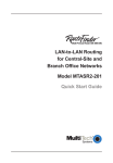
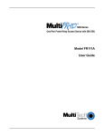
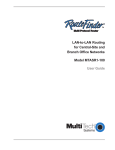
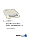
Router/Two-Port Frame Relay Access Device
Model FR2201
Quick Start Guide
Quick Start Guide
82092700 Revision A
MultiFRAD Model FR2201 (MultiFRAD II)
This publication may not be reproduced, in whole or in part, without
prior expressed written permission from Multi-Tech Systems, Inc. All
rights reserved.
Copyright © 1998, by Multi-Tech Systems, Inc.
Multi-Tech Systems, Inc. makes no representations or warranties
with respect to the contents hereof and specifically disclaims any
implied warranties of merchantability or fitness for any particular
purpose. Furthermore, Multi-Tech Systems, Inc. reserves the right
to revise this publication and to make changes from time to time in
the content hereof without obligation of Multi-Tech Systems, Inc. to
notify any person or organization of such revisions or changes.
Record of Revisions
Revision
Description
A
Manual released. All pages at revision A.
(10/2/98)
Patents
This Product is covered by one or more of the following U.S.
Patent Numbers: 5.301.274; 5.309.562; 5.355.365; 5.355.653;
5.452.289; 5.453.986. Other Patents Pending.
TRADEMARK
Trademark of Multi-Tech Systems, Inc. are MultiFRAD, MultiFRAD
II, and the Multi-Tech logo.
Windows is a registered trademark of Microsoft.
Multi-Tech Systems, Inc.
2205 Woodale Drive
Mounds View, Minnesota 55112
(612) 785-3500 or (800) 328-9717
Fax 612-785-9874
Tech Support (800) 972-2439
MultiRouter 200-Series Quick Start Guide
Contents
Introduction ................................................................................... 6
Related Documentation ................................................................. 7
Unpacking your MultiFRAD II ........................................................ 8
Cabling your MultiFRAD II ............................................................. 9
Installing your Software ................................................................ 11
Limited Warranty ......................................................................... 25
Service ........................................................................................ 26
v
MultiFRAD II Quick Start Guide
Introduction
Welcome to Multi-Tech's new MultiFRAD II™, model FR2201, a
Router/ Two-Port Frame Relay Access Device (FRAD) that
encapsulates non-packetized data streams from serial and LAN
devices into frame relay frames and frames that data with header and
trailer information prior to sending it to a frame relay network. The
MultiFRAD enables non-frame relay devices to connect to a
common carrier frame relay network service or private frame relay
network. The FR2201 is designed with channels to two non-frame
relay devices, an Ethernet LAN connection for IP or IPX routing or
bridging, and a trunk interface to a Frame Relay network. On the
receiving end of the communication, the MultiFRAD strips away the
frame relay control information so the target device receives the data
packaged in its original form.
Since frame relay networks use shared resources, they typically
are more reliable and less expensive per month than equivalent
leased lines. Depending on the location and distances between
points, simple point-to-point networks can cost less per month than
leased lines. The cost savings are even greater when multiple
leased lines are replaced with frame relay.
The FR2201 has two data ports for Data Terminal Equipment
(DTE) devices that are either asynchronous or HDLC
synchronous. A single Ethernet LAN connection is provided for IP
or IPX routing and Media Access Control (MAC) layer bridging for
all other protocols on either a 10Base-T or AUI port connection.
The trunk connection provides the link to a synchronous Data
Communications Equipment (DCE) device for access to the Frame
Relay network.
®
ech
TSystems
Figure 1. MultiFRAD II
6
Introduction
Related Documentation
This MultiFRAD Quick Start Guide is intended to be used by
qualified systems administrators and network managers. This
quick start guide provides the necessary information for a
qualified person to unpack, cable, install software, and
configure the unit for proper operation.
A detailed MultiFRAD User Guide is also provided with your
unit. The user guide provides in-depth information on the
features and functionality of Multi-Tech’s MultiFRAD. The User
Guide is provided in disk form and is also available from our
Web site.
The disk version is produced using Adobe Acrobat. To view or
print your copy of a user guide, load Adobe Acrobat Reader on
your system. Adobe Acrobat Reader can be downloaded from
Adobe’s Web site at:
http://www.adobe.com/prodindex/acrobat/readstep.html
Launch the Reader and open the .pdf file that is on the disk.
Viewing and printing a user guide from the Web also requires
that you have the Adobe Acrobat Reader loaded on your
system. The MultiFRAD II User Guide is also available on
Multi-Tech’s Web site at:
http://www.multitech.com
From the MTS home page, click Support | Manuals | MultiFRAD and choose MultiFRAD II to download the .pdf file.
7
MultiFRAD II Quick Start Guide
Unpacking your MultiFRAD II
Remove all items from the box.
®
Tech
Systems
MADE
IN U.S
.A
MADE IN
U.S.A
Figure 2. Unpacking
8
Cabling
Cabling your MultiFRAD II
Cabling your MultiFRAD involves making the proper Power,
Command Port, Ethernet, and Channel connections. Figure 3
shows the back panel connectors and the associated cable
connections. The MultiFRAD II supports up to 2 data channels.
Table 1 details the procedures for connecting the cables to your
MultiFRAD.
ETHERNET
10BASE T
AUI
CHANNEL 2
COMMAND PORT
CHANNEL 1
TRUNK (RS232/V.35)
POWER
Power Connection
T1 CSU/DSU or Comparable
Link Device
Ethernet Connection
Back-to-Back Cables
to Channel Devices
Command Port Connection
Figure 3. Cable Connections
9
MultiFRAD II Quick Start Guide
Table 1. Cabling Procedure
Step
1
Procedure
Connect one end of a DB25 back-to-back cable to each of
the data channel connectors on the back of your
MultiFRAD (labeled CHANNEL 1-2). See Figure 3.
Connect the other end of each cable to a channel device.
NOTE: Both channels support the RS232/V.35 protocols,
and either asynchronous or HDLC synchronous RS232
data equipment such as multiplexers.
2
Connect one end of an DB25 (female) cable to the Trunk
connector (Figure 3). Connect the other cable end to your
T1 CSU/DSU or compatible link device.
3
To make the network connection, connect an RJ45 (UTP)
cable to the 10 BASE-T Ethernet connector or the male
connector for a 10Base5 cable to the AUI Ethernet
connector (shown in Figure 3). Connect the other end of
the cable to your LAN.
4
Connect the MultiFRAD to your PC with a standard RS232
cable. Plug the male end of the cable into the Command
Port (Figure 3) and the other end into the PC’s serial port.
5
Connect one end of the power supply to a live AC outlet,
then connect the other end to the MultiFRAD as shown in
Figure 3. The Power connector is a 7-pin circular DIN
connector.
6
Apply power to the MultiFRAD by setting the Power switch
(Figure 3) to the “1” (on) position.
At this time your MultiFRAD is completely cabled. Proceed to the
next section to install your software.
10
Software
Installing your Software
The following procedure does not provide every screen or option
used in the process of installing the MultiFRAD software. The
assumption is that a technical person with a thorough knowledge
of Windows and the software loading process is doing the
installation. Additional information on the MultiFRAD software is
provided in the User Guide supplied with your MultiFRAD II.
1. Run Windows on the PC that is connected to the
Command Port.
2. Insert the MultiFRAD II disk 1 into the disk drive on the PC
that is connected to the Command Port.
3. Win3.1 users - access Run by clicking the File menu in
Program Manager and then click Run. In the Run dialog
box, type a:\setup or b:\setup (depending on the letter of
your disk drive) in the Command Line field and then click
OK.
Win95 users - click the Start box and then click Run. In
the Run dialog box click the down arrow and choose
a:\setup.exe or b:\setup.exe (depending on the letter of
your disk drive) in the Command Line field and then click
OK.
4. Click Next> to continue, then follow the on-screen
instructions to install your MultiFRAD software.
11
MultiFRAD II Quick Start Guide
The Choose Destination Location screen is displayed.
5. Click Browse to select a different folder for your
MultiFRAD software, or accept the default (MF2000) by
clicking Next> (or pressing the Enter key).
The Select Program Folder screen is displayed.
6. Click Next> to continue. After all the program files from
both disks are loaded, the Setup dialog box is displayed,
enabling you to designate the COM port of the PC that is
connected to your MultiFRAD. On the Select Port field,
click the down arrow and choose the COM port of your PC
(COM1 -- COM4) that is connected to your MultiFRAD.
12
Software
7. Click OK to continue. The Setup Complete screen is
displayed.
8. Click Finish to continue configuring your MultiFRAD.
The Do you want to download default setup? dialog
box is displayed.
9. Click Yes to continue. A series of five Setup and
Configuration dialog boxes will now be displayed. The OnLine Help system provides detailed explanations of each
dialog box and option. To access Help, click the ? button
on the dialog box for which you need additional
information.
13
MultiFRAD II Quick Start Guide
If your network protocol is IPX, continue with the following
steps. If your network protocol is IP, click the IPX Routing
Enable check box to clear it and disable IPX, then click
OK and proceed to step 14.
10. Router Name: You can either use the default Router
Name (MultiFRAD 2000) or assign a new Router Name in
this field. The Router Name must be a printable ASCII
string of a maximum of 47 characters. The MultiFRAD
uses this name to advertise its service throughout the IPX
internetwork.
11. Ethernet: You can enable Auto Learn Network Numbers
by leaving the default Yes or you can click on No (each
Network number field will then become active) and
manually assign the network numbers here.
If no file server is connected to the Ethernet segment, then
this field should be No (recommended).
If you enable Auto Learn (Yes), the MultiFRAD will learn
the IPX network numbers from the file server.
If you select No for Auto Learn, record the network
numbers assigned by the network file server for each of
the four frame types (Raw (802.3), LLC (802.2), EthernetII
(Type II), SNAP) in the space provided below.
14
Software
RAW (802.3) Frames Network Number _____________
LCC (802.2) Frames Network Number ______________
TYPE_II Frames Network Number _________________
SNAP Frames Network Number ___________________
WAN Network Number __________________________
When you manually assign network numbers, you must
make sure they match the network numbers assigned to
your local file server (if any).
12. WAN: Enter the WAN network number for the Frame
Relay WAN Port by clicking the Network Number box,
backspacing through the default number, and entering
your new WAN Number. Make sure the WAN network
number is the same as the MultiFRAD on the other end of
the link.
The WAN network number has to be assigned by the
Network Administrator and must be unique throughout the
entire internetwork.
Note: The WAN port does not have the capability of
learning the network number, unlike the LAN port (i.e., the
WAN port does not have a file server).
13. Click OK when you are satisfied with your selections.
14. If you clicked OK from the IPX Protocol Default Setup
dialog box (step 9), the IP Protocol Default Setup dialog
box is displayed.
15. To change the IP parameters, proceed to the next step.
Clicking OK advances to the WAN Ports Default Setup
dialog box. The WAN Ports Default Setup starts at step
21.
15
MultiFRAD II Quick Start Guide
16. The default Ethernet IP Address has to be changed to your
unique LAN address. Enter an acceptable, unique IP
address in the Ethernet port IP Adress field.
17. Change the default Subnet Mask and Frame Type to the
values you have assigned to your LAN port.
18. The default WAN Address has to be changed to your
unique WAN address. Assign an acceptable unique WAN
Address to the WAN port.
19. Change the default Subnet Mask and Remote Address
for WAN to the values you have assigned to your WAN.
20. Click OK when you are satisfied with your selections.
21. The WAN Ports Default Setup dialog box is displayed.
The WAN Port is enabled in this dialog box. Frame Relay
is also enabled. If your WAN port is going to be used in
Point-to-point protocol, click Enable PPP. When PPP is
enabled, the Modem Command Setup field becomes
active and either Asynchronous or Direct Connect needs
to be checked (enabled).
The WAN port can be further configured (after the
software installation is completed) by clicking the
MultiFRAD Configuration icon and then clicking the WAN
button.
22. Click OK on the WAN Ports Default Setup dialog box.
23. The Data Port Configuration dialog box enables you to
individually configure the two data channels (Port 1 and
Port 2).
If you are connecting to a synchronous device, ensure that
16
Software
the Clocking type and Speed (for Internal clock only) are
correct. Also, check that the Encoding Scheme, Between
Frames, and InterFrame Timer settings are correct for
your channel device. Refer to user documentation for the
parameters of the channel device.
If you are connecting to an Asynchronous data device,
select Asynchronous, then select the maximum Speed in
the drop-down list. Refer to the user documentation for the
parameters of the data device.
24. Click OK when you are satisfied with the configurations for
both data ports.
25. If you enabled PPP in the WAN Ports Default Setup dialog
box, proceed to step 37.
17
MultiFRAD II Quick Start Guide
If you enabled Frame Relay in the WAN Ports Default
Setup dialog box, the Frame Relay DLCI Default Setup
dialog box is displayed with all the groups inactive.
When your MultiFRAD is connected to an active frame
relay network service, it can detect DLCIs and the frame
relay management type. However, at this point your
MultiFRAD is not yet communicating with the frame relay
network. Continue with the next step iff you know your
DLCIs and want to add them manually. Otherwise, if you
want them added automatically after your MultiFRAD is
communicating with the frame relay network, proceed to
step 37 to finish installing your software.
26. Click New (+/-) and the Frame Relay New DLCI dialog box
is displayed with the Enter DLCI Number field active.
Enter a DLCI number that was provided by your service
provider at subscription time.
27. Click OK. The Frame Relay DLCI Default Setup dialog box
is displayed with all the groups active and your DLCI
displayed in the DLCIs field.
You can map a protocol stack and/or data port to a DLCI.
18
Software
28. To map this DLCI to a protocol stack, click the down arrow
for each protocol that your LAN uses. Select a logical IP
WAN address or logical IPX network number from each
list.
29. To map this DLCI to a data port, in the Port Mappings
group click the Port number(s) you want to associate with
this DLCI.
30. Ensure that Throttle Up and Down is selected in the
Congestion Management group.
31. Ensure that Adhere to CIR + Be is selected in the Mode
group. Multi-Tech recommends using this setting initially.
32. Click the Committed Information Rate text box in the
Settings (in Bits/second) group and enter the CIR value
your service provider supplied for this DLCI.
33. Click the Excess Burst Rate (Be) text box in the Settings
(in Bits/second) group and enter the Be value your
service provider supplied for this DLCI.
34. The Compression option may be useful at low link
speeds; however, do not use this feature with a high speed
link.
35. Click the Management type supported by the Frame
Relay network. The network management type is supplied
by your service provider at subscription time.
36. Repeat steps 26 through 35 for each new DLCI.
19
MultiFRAD II Quick Start Guide
37. The Checking MultiFRAD dialog box is displayed.
The Setup utility is "Ready to Download default setup
Choose OK to proceed." Click OK to proceed.
38. Writing Setup dialog box is displayed as the setup
configuration is written to the MultiFRAD.
39. After the setup is written to the MultiFRAD, the unit
reboots.
40. Check that the Fail LED on the MultiFRAD is Off after the
download is complete and the MultiFRAD is rebooted.
41. Win3.1 users - you are returned to your Program
Manager where the MultiFRAD Program Group and
20
Software
Program Item (Windows icons) have been created.
Win95 users - you are returned to your MultiFRAD
2000folder which will be visible on your desktop.
Your MultiFRAD is operational at this time.
42. If you need to further configure your MultiFRAD once the
software is installed, proceed with the following:
Win3.1 users - from the Program Manager, click the
MultiFRAD Configuration icon in the MultiFRAD 2000
Program Group. The main Setup dialog box is displayed.
Win95 users - from your desktop, click Programs,
MultiFRAD 2000, then MultiFRAD Configuration. The
main Setup dialog box is displayed.
43. On the main Setup dialog box, click Frame Relay.
44. A Frame Relay dialog box stating “MultiFRAD has
detected and added following DLCIs.” is displayed.
21
MultiFRAD II Quick Start Guide
Click OK.
45. A second Frame Relay dialog box is displayed, stating
“MultiFRAD has detected Management Type to be Annex
D. Hence it has set Management type to Annex D from
LMI”. The Management Types are Annex A, Annex D, or
LMI. Any one of them could appear in this dialog box.
Click OK and the Frame Relay DLCI dialog box is
displayed.
46. Click the DLCI you want to map. The Protocol Mappings,
Port Mappings, and all the other groups become active.
47. To map this DLCI to a protocol stack, click a protocol
stack’s down arrow for each protocol that your LAN is
22
Software
using. each protocols drop-down list displays “None” and
your logical IP WAN addresses and/or logical IPX network
numbers.
48. To map this DLCI to a data port, in the Port Mappings
group click the Port number(s) you want to associate with
this DLCI.
49. Ensure that Throttle Up and Down is selected in the
Congestion Management group.
50. Ensure that Adhere to CIR + Be is selected in the Mode
group. Multi-Tech recommends using this setting initially.
51. Click the Committed Information Rate text box in the
Settings (in Bits/second) group and enter the CIR value
your service provider supplied for this DLCI.
52. Click the Excess Burst Rate (Be) text box in the Settings
(in Bits/second) group and enter the Be value your
service provider supplied for this DLCI.
53. The Compression option may be useful at low link
speeds; however, do not use this feature with a high
speed link.
54. Repeat steps 46 through 53 for each new DLCI.
55. Click OK when you are satisfied with all your selections.
56. The Writing Setup dialog box is displayed as the setup
configuration is written to the MultiFRAD.
57. After the setup is written to the MultiFRAD, the unit
reboots.
23
MultiFRAD II Quick Start Guide
58. Check that the FailLED on the MultiFRAD is Off after the
download is complete and the MultiFRAD is rebooted.
59. Win3.1 users - you are returned to your Program
Manager where the MultiFRAD 2000 Program Group and
Program Item (Windows icons) have been created.
Win95 users - you are returned to your MultiFRAD 2000
folder which will be visible on your desktop.
Your MultiFRAD is operational at this time.
24
Warranty and Service Information
Limited Warranty
Multi-Tech Systems, Inc. (“MTS”) warrants that its products will be
free from defects in material or workmanship for a period of two
years from the date of purchase, or if proof of purchase is not
provided, two years from date of shipment. MTS MAKES NO
OTHER WARRANTY, EXPRESSED OR IMPLIED, AND ALL
IMPLIED WARRANTIES OF MERCHANTABILITY AND FITNESS
FOR A PARTICULAR PURPOSE ARE HEREBY DISCLAIMED.
This warranty does not apply to any products which have been
damaged by lightning storms, water, or power surges or which
have been neglected, altered, abused, used for a purpose other
than the one for which they were manufactured, repaired by the
customer or any party without MTS’s written authorization, or used
in any manner inconsistent with MTS’s instructions.
MTS’s entire obligation under this warranty shall be limited (at
MTS’s option) to repair or replacement of any products which
prove to be defective within the warranty period, or, at MTS’s
option, issuance of a refund of the purchase price. Defective
products must be returned by Customer to MTS’s factory
transportation prepaid.
MTS WILL NOT BE LIABLE FOR CONSEQUENTIAL DAMAGES
AND UNDER NO CIRCUMSTANCES WILL ITS LIABILITY
EXCEED THE PURCHASE PRICE FOR DEFECTIVE
PRODUCTS.
25
MultiFRAD II Quick Start Guide
Service
Multi-Tech has an excellent staff of technical support personnel
available to help you get the most out of your Multi-Tech product.
Refer to your MultiFRAD II User Guide for Warranty and Service
information.
NOTE: This equipment has been tested and found to comply with
the limits for a Class A digital device, pursuant to Part 15 of the
FCC Rules. These limits are designed to provide reasonable
protection against harmful interference when the equipment is
operated in a commercial installation. This equipment generates,
uses and can radiate radio frequency energy, and if not installed
and used in accordance with the instructions, may cause harmful
interference to radio communications. Operation of this equipment
in a residential area is likely to cause harmful interference in which
case the user will be required to correct the interference at his own
expense.
Warning: Changes or modifications to this unit not expressly
approved by the party responsible for compliance could void the
user's authority to operate the equipment.
26
Warranty and Service Information
82092700