1
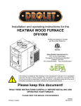
Installation and operating instructions for the
TUNDRA WOOD FURNACE
DF02000
Verified and tested for Canada
and the United States by :
Stove Builder International Inc.
250, rue de Copenhague,
St-Augustin-de-Desmaures (Quebec)
Canada G3A 2H3
Tel: (418) 878-3040 Fax: (418) 878-3001
This manual is available for free download on the manufacturer’s web site. It is a copyrighted
document. Re-sale is strictly prohibited. The manufacturer may update this manual from time
to time and cannot be responsible for problems, injuries, or damages arising out of the use of
information contained in any manual obtained from unauthorized sources.
Please keep this document!
READ THESE INSTRUCTIONS CAREFULLY BEFORE INSTALLING AND
OPERATING YOUR FURNACE.
PLEASE KEEP THIS MANUAL FOR REFERENCE
Printed in Canada
45656A
06-09-2013
Tundra Furnace Installation and Operation Manual
THANK YOU FOR CHOOSING THIS DROLET WOOD FURNACE
As one of North America’s largest and most respected wood stove, furnace and fireplace
manufacturers, Stove Builder International takes pride in the quality and performance of all
its products. We want to help you get maximum satisfaction as you use this product.
In the pages that follow you will find general advice on wood heating, detailed instructions
for safe and effective installation, and guidance on how to get the best performance from
this furnace as you build and maintain fires, and maintain your wood heating system.
We recommend that our wood burning hearth products be installed and serviced by
professionals who are certified in the United States by NFI (National Fireplace Institute®) or
in Canada by WETT (Wood Energy Technology Transfer) or in Quebec by APC
(Association des Professionnels du Chauffage).
Congratulations on making a wise purchase.
When this furnace is not properly installed, a house fire may result. To reduce the
risk of fire, follow the installation instructions. Contact local building or fire officials
about restrictions and installation inspection requirements in your area.
Please read this entire manual before you install and use your new furnace. Failure
to follow instructions may result in property damage, bodily injury, or even death. It
is important that you follow the installations guidelines exactly.
You may need to obtain a building permit for the installation of this furnace and the
chimney that it is connected to. Consult your municipal building department or fire
department before installation to determine the need to obtain one. We recommend
that you also inform your home insurance company to find out if the installation will
affect your policy.
REGISTER YOUR WARRANTY ONLINE
To receive full warranty coverage, you will need to show
evidence of the date you purchased your furnace. Keep your
sales invoice. We also recommend that you register your
warranty online at:
http://www.drolet.ca/en/service-support/warranty-registration
Registering your warranty online will help us to quickly track the
information we need about your furnace.
2
Tundra Furnace Installation and Operation Manual
Table of contents
INTRODUCTION..................................................................................... 6 PART A - OPERATION AND MAINTENANCE ................................. 7 1 Safety information ............................................................................... 7 1.1 1.2 1.3 1.4 Summary of operation and maintenance cautions and warnings ........................... 7 Smoke detector ...................................................................................................... 8 Chimney fire ........................................................................................................... 8 Prolonged power outage ........................................................................................ 8 2 General information ............................................................................ 9 2.1 Drolet Tundra furnace specifications ...................................................................... 9 2.1.1 Technical data Tundra ...................................................................................... 10 2.1.2 General technical data ...................................................................................... 11 2.2 The benefits of low emissions and high efficiency ................................................ 12 2.3 The SBI commitment to you and the environment................................................ 12 2.3.1 What is your new furnace made of? .................................................................. 12 3 Fuel ..................................................................................................... 13 3.1 Materials that should not be burned ..................................................................... 13 3.2 How to prepare or buy good firewood .................................................................. 13 3.2.1 What is good firewood?..................................................................................... 13 3.2.2 Tree species ..................................................................................................... 13 3.2.3 Log length ......................................................................................................... 14 3.2.4 Piece size.......................................................................................................... 14 3.2.5 How to dry firewood .......................................................................................... 15 3.2.6 Judging firewood moisture content ................................................................... 16 4 Operating your furnace..................................................................... 17 4.1 Your first fires ....................................................................................................... 17 4.2 Lighting fires ......................................................................................................... 17 4.2.1 Conventional fire starting .................................................................................. 17 4.2.2 The top down fire .............................................................................................. 18 4.2.3 Two parallel logs ............................................................................................... 18 4.2.4 Using fire starters .............................................................................................. 18 4.3 Maintaining wood fires.......................................................................................... 19 4.3.1 General advice .................................................................................................. 19 3
Tundra Furnace Installation and Operation Manual
4.3.2 Raking charcoal ................................................................................................ 20 4.3.3 Firing each new hot load ................................................................................... 20 4.3.4 Control of the air supply .................................................................................... 21 4.3.5 Building different fires for different needs .......................................................... 22 4.4 The use of a thermometer .................................................................................... 23 4.4.1 Safety ................................................................................................................ 23 4.4.2 Combustion efficiency ....................................................................................... 24 4.4.3 Protect your furnace .......................................................................................... 24 4.4.4 Control of the air inlet damper ........................................................................... 24 4.5 Ash drawer ........................................................................................................... 24 5 Maintaining your wood heating system ........................................... 25 5.1 Furnace maintenance........................................................................................... 25 5.1.1 Ash removal ...................................................................................................... 25 5.1.2 Cleaning door glass .......................................................................................... 25 5.1.3 Door adjustment ................................................................................................ 26 5.1.4 Replacement of the glass and gaskets ............................................................. 27 5.1.5 Cleaning and painting the furnace .................................................................... 29 5.1.6 Heat exchangers care ....................................................................................... 29 5.2 Chimney and chimney connector maintenance .................................................... 33 5.2.1 Why chimney cleaning is necessary ................................................................. 33 5.2.2 How often should you clean the chimney? ........................................................ 33 5.2.3 Cleaning the chimney........................................................................................ 34 5.3 Smoke pipe inspection ......................................................................................... 34 5.4 Blower motor maintenance ................................................................................... 34 PART B - INSTALLATION .................................................................. 35 6 Safety information ............................................................................. 35 6.1 6.2 6.3 6.4 6.5 6.6 Summary of installation cautions and warnings.................................................... 35 Regulations covering furnace installation ............................................................. 35 Connecting pipe, manual and barometric damper ................................................ 36 Chimney and draft ................................................................................................ 37 Combustion air ..................................................................................................... 38 Filter ..................................................................................................................... 40 7 Setting up the unit and clearances ................................................... 40 7.1 7.2 4
Unit location ......................................................................................................... 40 Location of the certification label .......................................................................... 40 Tundra Furnace Installation and Operation Manual
7.3 Clearances to combustible material ..................................................................... 40 7.4 Floor protector ...................................................................................................... 42 7.5 Hot air distribution system .................................................................................... 44 7.5.1 Authorized configurations in Canada and United States ................................... 48 7.5.2 Authorized configurations in United States only ................................................ 48 7.5.3 Non-authorized configuration, Canada and United States ................................ 49 8 The venting system ............................................................................ 50 8.1 General ................................................................................................................ 50 8.2 Suitable chimneys ................................................................................................ 50 8.2.1 Factory-built metal chimneys ............................................................................ 51 8.2.2 Masonry chimneys ............................................................................................ 51 8.3 Minimum chimney height ...................................................................................... 52 8.4 Relationship between the chimney and the house ............................................... 52 8.4.1 Why inside chimneys are preferred ................................................................... 52 8.4.2 Why the chimney should penetrate the highest heated space .......................... 53 8.5 Supply of combustion air ...................................................................................... 54 8.6 Air supply in conventional houses ........................................................................ 54 8.7 Installing the chimney connector .......................................................................... 54 8.7.1 Installation of single wall chimney connector .................................................... 55 9 Electrical connections and controls .................................................. 57 9.1 9.2 9.3 Wiring diagram ..................................................................................................... 57 Manual or thermostat control ................................................................................ 59 Fan control ........................................................................................................... 59 Appendix 1: Optional thermostat installation ...................................... 61 Appendix 2: Optional filter (AC01390) ................................................. 63 Appendix 3: Fresh air return adapter (AC01392) ............................... 64 Appendix 4: Installation of secondary air tubes and baffle ................ 65 Appendix 5: Troubleshooting ................................................................ 67 Appendix 6: Exploded diagram and parts list ...................................... 68 DROLET LIMITED LIFETIME WARRANTY ................................. 71 5
Tundra Furnace Installation and Operation Manual
INTRODUCTION
Take note that this furnace uses the same wood burning technology as a high efficiency
EPA certified wood burning furnace. This applies to the lighting, the ember bed, and the
minimum combustion air intake which was calibrated to burn good seasoned cordwood.
This model line is certified as meeting the emissions limits in 40 C.F.R. part 60, section
60.532 (B) per EPA methods 28 and 5G-3, February 1991.
Emissions: 6.6 g/h or 0.229 g/MJ
Average efficiency: 76 % (LHV) / 71% (HHV)
To optimize the efficiency of your furnace, here is some advice that you should follow
when installing or operating your Tundra furnace:
Respect the local codes (when in doubt, consult your local dealer);
Check the specifications on the certification label about the clearances. Make sure that
they correspond to those included in the instruction manual.
Make sure your furnace is installed according to the instructions on the certification
label;
The furnace is fully assembled at the factory and no electrical connection is required
other than plugging the power cord into an outlet. It does not include automatic variable
speed control of the fan. Factory connection is on speed 2 (medium-low) but can be
modified. The blower speed must conform to the recommendations of the Warm Air
Heating and Air Conditioning National Association and should respect the static
pressure ranges in the warm air plenum of the furnace (see section 2.1.2, General
technical data.
We recommend that our woodburning hearth products be installed and serviced by
professionals who are certified in the United States by NFI (National Fireplace
Institute®) or in Canada by WETT (Wood Energy Technical Training) or in Quebec by
APC (Association des Professionnels du Chauffage).
6
Tundra Furnace Installation and Operation Manual
PART A - OPERATION AND MAINTENANCE
Please see Part B for installation instructions.
1 Safety information
1.1 Summary of operation and maintenance cautions and warnings
HOT WHILE IN OPERATION, KEEP CHILDREN, CLOTHING AND FURNITURE
AWAY. CONTACT MAY CAUSE SKIN BURNS. GLOVES MAY BE NEEDED FOR
FURNACE OPERATION.
USING A FURNACE WITH CRACKED OR BROKEN COMPONENTS, SUCH AS
GLASS OR FIREBRICKS OR BAFFLES MAY PRODUCE AN UNSAFE CONDITION
AND MAY DAMAGE THE FURNACE.
OPEN THE AIR CONTROL FULLY BEFORE OPENING FIRING DOOR.
OPERATE ONLY WITH DOOR FULLY CLOSED. IF DOOR IS LEFT PARTLY OPEN,
GAS AND FLAME MAY BE DRAWN OUT OF THE OPENING, CREATING RISKS
FROM BOTH FIRE AND SMOKE.
THIS FURNACE IS NOT DESIGNED TO BE USED WITH THE DOOR OPEN. THE
DOOR MAY BE OPEN ONLY DURING LIGHTING PROCEDURES OR RELOADING.
DO NOT LEAVE THE FURNACE UNATTENDED WHEN THE DOOR IS SLIGHTLY
OPENED DURING IGNITION. ALWAYS CLOSE THE DOOR AFTER IGNITION.
NEVER USE GASOLINE, GASOLINE-TYPE LANTERN FUEL (NAPHTHA), FUEL
OIL, MOTOR OIL, KEROSENE, CHARCOAL LIGHTER FLUID, OR SIMILAR
LIQUIDS OR AEROSOLS TO START OR ‘FRESHEN UP’ A FIRE IN THIS
FURNACE. KEEP ALL SUCH LIQUIDS OR AEROSOLS WELL AWAY FROM THE
FURNACE WHILE IT IS IN USE.
DO NOT STORE FUEL WITHIN HEATER MINIMUM INSTALLATION CLEARANCES.
BURN ONLY SEASONED NATURAL FIREWOOD.
DO NOT BURN:
o
o
o
o
o
o
o
GARBAGE OF ANY KIND,
COAL OR CHARCOAL,
TREATED, PAINTED OR COATED WOOD,
PLYWOOD OR PARTICLE BOARD,
FINE PAPER, COLORED PAPER OR CARDBOARD,
SALT WATER DRIFTWOOD, OR
RAILROAD TIES.
DO NOT ELEVATE THE FIRE BY USING A GRATE IN THIS FURNACE.
7
Tundra Furnace Installation and Operation Manual
DO NOT INSTALL AN AUTOMATIC FEEDER ON THIS FURNACE.
DO NOT INSTALL A MANUAL DAMPER ON THIS FURNACE.
THIS APPLIANCE SHOULD BE MAINTAINED AND OPERATED AT ALL TIMES IN
ACCORDANCE WITH THESE INSTRUCTIONS.
1.2 Smoke detector
We highly recommend the use of a smoke detector. It must be installed at least 15 feet
(4.57 m) from the appliance in order to prevent undue triggering of the detector when
reloading.
1.3 Chimney fire
A Chimney fire will happen when the flame from an uncontrollable fire ignites the sooth
and creosote deposits in a neglected venting system. It will often happen when burning
cardboard, branches or small dry pieces of wood. The first signs of a chimney fire are:
1. A rumble.
2. Smoke pipe becomes extremely hot.
3. Sparks or even flames shoot out of the chimney
In the event of a chimney fire, first call your local fire department and water the roof
in the vicinity of the chimney.
Make sure that the furnace door and the air intake damper are closed (if need be, lower
the thermostat setting and CLOSE the barometric draft damper manually if one is installed.
In the event of uncontrollable fire (caused by wrongful operation or excessive chimney
draft), follow the same procedure as in a chimney fire but you must then OPEN the
barometric draft damper manually if one is installed.
1.4 Prolonged power outage
To reduce the risk of overheating during a prolonged power outage (more than 10
minutes), it is recommended damper is closed. If your furnace is equipped with the
optional filter, remove the air filter to improve the circulation of air around the combustion
chamber of the Tundra furnace. Do not load the furnace more than 50 percent of its
capacity to prevent the risk of overheating,
8
Tundra Furnace Installation and Operation Manual
2
General information
2.1 Drolet Tundra furnace specifications
Combustible
Maximum heat input
Maximum heat output
Average heat output
Thermostatic control
Maximum efficiency
Average emissions
Loading capacity
Burn time*
Heating capacity*
Flue outlet size
Recommended smoke pipe dimension
Required chimney type
Recommended chimney size
Type of door
Dimensions of the hot air outlet
Dimensions of the cold air return
Dimensions of ash drawer
Thickness of steel (firebox)
Minimum clearance (in front of furnace)
Minimum clearance (rear of furnace )
Minimum clearance (sides of furnace )
Minimum clearance (standard ducts)
Recommended service clearance
Weight
Color
Warranty
Standards – security
Standards – emissions / efficiency
Maximum log length
Wood
125,000 BTU (36,6 kW)
95,000 BTU (27,92 kW)
62,000 BTU (18,2 kW)
Optional
76% (LHV) / 71% (HHV)
6.6 grams/hr ou 0,229 g/MJ
Up to 55 lb (25 kg)
2h to 10h
500 ft2 to 2,500 ft2 (46.5 m2 to 232 m2)
6" (152 mm)
6" (152 mm)
2,100 °F (1150 °C)
6" (152 mm)
Cast iron with ceramic glass
Two 8" round outlet
20" H x 15" L Optional
20" L x 4 3/8" P
3/16" (5 mm)
48"
24"
11"
2" for the first 6 feet and 1" after
24”
550 lb (250 kg), with blower
Grey
Limited lifetime
CSA B366.1, UL391
EPA / CSA B415.1
22” over depth**
* Burn time and heating capacity may vary subject to hot air distribution system, chimney
draft, chimney diameter, locality, heat loss factors, climate, fuels and other variables.
** Over width: through the door you see the sides of the logs; over depth: through the door
you see the ends of the logs
9
Tundra Furnace Installation and Operation Manual
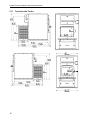
2.1.1 Technical data Tundra
10
Tundra Furnace Installation and Operation Manual
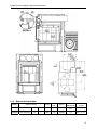
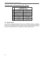
2.1.2
General technical data
MODEL
TUNDRA
(DIRECT DRIVE)
FLOW
TEMP
VAR.
BTU/ H
VENT
MOT.
VIT.
(CFM)
(°F)
(WOOD)
DCT-916-800-5
1/4
4
1400
135
125,000
STATIC
PRESSURE
INCH OF
W.C.
OPTIONAL
FILTER
0,2
20” x 15” x 1”
(IN)
11
Tundra Furnace Installation and Operation Manual
2.2 The benefits of low emissions and high efficiency
The low smoke emissions produced by the special features inside the Brand Model firebox
mean that your household will release up to 90 percent less smoke into the outside
environment than if you used an older conventional wood furnace. But there is more to the
emission control technologies than protecting the environment.
The smoke released from wood when it is heated contains about half of the energy content
of the fuel. By burning the wood completely, your furnace releases all the heat energy from
the wood instead of wasting it as smoke up the chimney. Also, the features inside the
firebox allow you to reduce the air supply to control heat output, while maintaining clean
and efficient flaming combustion, which boosts the efficient delivery of heat to your home.
The emission control and advanced combustion features of your furnace can only work
properly if your fuel is in the correct moisture content range of 15 to 20 percent. See
Section 3 of this manual for suggestions on preparing fuel wood and judging its moisture.
2.3 The SBI commitment to you and the environment
The SBI team are committed to protecting the environment, so we do everything we can to
use only materials in our products that will have no lasting negative impact on the
environment.
2.3.1 What is your new furnace made of?
The body of your furnace, which is most of its weight, is carbon steel. Should it ever
become necessary many years in the future, almost the entire furnace can be recycled into
new products, thus eliminating the need to mine new materials.
The paint coat on your furnace is very thin. Its VOC content (Volatile Organic
Components) is very low. VOCs can be responsible for smog, so all the paint used during
the manufacturing process meets the latest air quality requirements with regards to VOC
reduction or elimination.
The air tubes are stainless steel, which can also be recycled.
Vermiculite is used for the baffle. Vermiculite is a mineral. Large commercial mines exist in
China, Russia, South Africa, and Brazil. Potassium silicate is used as binder to form a
rigid board. Vermiculite can withstand temperatures above 2,000 °F. It is not considered
hazardous waste. Disposal at a landfill is recommended.
Lightweight firebrick is made of pumice and cement. Pumice is in fact volcanic rock, a
naturally green product found in the Northwest United States. Disposal at a landfill is
recommended.
The door and glass gaskets are fibreglass which is spun from melted sand. Black gaskets
have been dipped into a solvent-free solution. Disposal at a landfill is recommended.
The door glass is a 5 mm thick ceramic material that contains no toxic chemicals. It is
basically made of raw earth materials such as sand and quartz that are combined in such
12
Tundra Furnace Installation and Operation Manual
a way to form a glass at high temperatures. Ceramic glass will not re-melt in the same
way as normal glass, so it should not be recycled with your regular household products.
Disposal at a landfill is recommended.
3 Fuel
3.1 Materials that should not be burned
•
GARBAGE OF ANY KIND,
•
COAL OR CHARCOAL,
•
TREATED, PAINTED OR COATED WOOD,
•
PLYWOOD OR PARTICLE BOARD,
•
FINE PAPER, COLORED PAPER OR CARDBOARD,
•
SALT WATER DRIFTWOOD
•
ALL MANUFACTURED LOGS
•
RAILROAD TIES
•
LIQUIDS SUCH AS KEROSCENE OR DIESEL FUEL TO START A FIRE
3.2 How to prepare or buy good firewood
3.2.1 What is good firewood?
Good firewood has been cut to the correct length for the furnace, split to a range of sizes
and stacked in the open until its moisture content is reduced to 15 to 20 per cent.
3.2.2 Tree species
The tree species the firewood is produced from is less important than its moisture content.
The main difference in firewood from various tree species is the density of the wood.
Hardwoods are denser than softwoods. People who live in the coldest regions of North
America usually have only spruce, birch and poplar, other low-density species to burn and
yet they can heat their homes successfully.
Homeowners with access to both hardwood and softwood fuel sometimes use both types
for different purposes. For example, softer woods make good fuel for relatively mild
weather in spring and fall because they light quickly and produce less heat Softwoods are
not as dense as hardwoods so a given volume of wood contains less energy. Using
softwoods avoids overheating the house, which can be a common problem with wood
heating in moderate weather. Harder woods are best for colder winter weather when more
heat and longer burn cycles are desirable.
13
Tundra Furnace Installation and Operation Manual
Note that hardwood trees like oak, maple, ash and beech are slower growing and longer
lived than softer woods like poplar and birch. That makes hardwood trees more valuable.
The advice that only hardwoods are good to burn is outdated. Old, leaky cast iron furnaces
wouldn’t hold a fire overnight unless they were fed large pieces of hardwood. That is no
longer true. You can successfully heat your home by using the less desirable tree species
and give the forest a break at the same time.
3.2.3 Log length
Logs should be cut about 1” (25 mm) shorter than the firebox so they fit in easily. Pieces
that are too long make loading the furnace very difficult. The most common standard
length of firewood is 16” (400 mm).
The pieces should be a consistent length, with a maximum of 1” (25 mm) variation from
piece to piece.
3.2.4 Piece size
Firewood dries more quickly when it is split. Large unsplit rounds can take years to dry
enough to burn. Even when dried, unsplit logs are difficult to ignite because they don’t
have the sharp edges where the flames first catch. Logs as small as 3” (75 mm) should be
split to encourage drying.
14
Tundra Furnace Installation and Operation Manual
Wood should be split to a range of sizes, from about 3” to 6” (75 mm to 150 mm) in cross
section. Having a range of sizes makes starting and rekindling fires much easier. Often,
the firewood purchased from commercial suppliers is not split finely enough for convenient
stoking. It is sometimes advisable to resplit the wood before stacking to dry.
3.2.5 How to dry firewood
Firewood that is not dry enough to burn is the cause of most complaints about wood
inserts. Continually burning green or unseasoned wood produces more creosote and
involves lack of heat and dirty glass door. See Section 5: Maintaining your wood
heating system for concerns about creosote.
Here are some things to consider in estimating drying time:
•
•
•
•
•
•
•
firewood takes a long time to dry
firewood bought from a dealer is rarely dry enough to burn, so it is advisable to buy the
wood in spring and dry it yourself
drying happens faster in dry weather than in damp, maritime climates
drying happens faster in warm summer weather than in winter weather
small pieces dry more quickly than large pieces
split pieces dry more quickly than unsplit rounds
softwoods take less time to dry than hardwoods
15
Tundra Furnace Installation and Operation Manual
•
•
•
•
softwoods like pine, spruce, and poplar/aspen can be dry enough to burn after being
stacked in the open for only the summer months
hardwoods like oak, maple and ash can take one, or even two years to dry fully,
especially if the pieces are big
firewood dries more quickly when stacked in the open where it is exposed to sun and
wind; it takes much longer to dry when stacked in a wood shed
firewood that is ready to burn has a moisture content between15 and 20% by weight
and will allow your furnace to produce its highest possible efficiency
3.2.6 Judging firewood moisture content
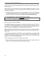
You can find out if some firewood is dry enough to burn by using these guidelines:
•
•
•
•
•
•
cracks form at the ends of logs as they dry
as it dries in the sun, the wood turns from white or cream coloured to grey or yellow,
bang two pieces of wood together; seasoned wood sounds hollow and wet wood
sounds dull,
dry wood is much lighter in weight than wet wood,
split a piece, and if the fresh face feels warm and dry it is dry enough to burn; if it feels
damp, it is too wet,
burn a piece; wet wood hisses and sizzles in the fire and dry wood does not.
You could buy a wood moisture meter to test your
firewood.
16
Tundra Furnace Installation and Operation Manual
4 Operating your furnace
4.1 Your first fires
Two things will happen as you burn your first few fires; the paint cures and the internal
components of the furnace are conditioned.
As the paint cures, some of the chemicals vaporize. The vapours are not poisonous, but
they do smell bad. Fresh paint fumes can also cause false alarms in smoke detectors. So,
when you first light your furnace, be prepared by opening doors and/or windows to
ventilate the house. As you burn hotter and hotter fires, more of the painted surfaces reach
the curing temperature of the paint. The smell of curing paint does not disappear until you
have burned one or two very hot fires.
It is recommended to burn it at high rate and ventilate the building until the odours
disappear. Once the paint smell disappears, your furnace is ready for serious heating.
4.2 Lighting fires
Each person who heats with wood develops their own favourite method to light fires.
Whatever method you choose, your goal should be to get a hot fire burning quickly. A fire
that starts fast produces less smoke and deposits less creosote in the chimney. Here are
three popular and effective ways to start wood fires.
4.2.1 Conventional fire starting
The conventional way to build a wood
fire is to bunch up 5 to 10 sheets of
plain newspaper and place them in the
firebox. Next, place 10 or so pieces of
fine kindling on the newspaper. This
kindling should be very thin; less than
1” (25 mm). Next, place some larger
kindling pieces on the fine kindling.
Open the air control and light the
newspaper. If you have a tall, straight
venting system you should be able to
close the door immediately and the fire
will ignite. If your venting system has
elbows or an outside chimney, you may
need to leave the door closed but
unlatched for a few minutes as the
newspaper ignites and heat in the
chimney produces some draft. Once
the fire has ignited, close the door and
leave the air control open.
A conventional kindling fire with paper under
finely split wood.
DO NOT LEAVE THE FURNACE UNATTENDED WHEN THE DOOR IS SLIGHTLY
OPENED DURING IGNITION. ALWAYS CLOSE THE DOOR AFTER IGNITION.
17
Tundra Furnace Installation and Operation Manual
After the kindling fire has mostly burned, you can add firewood pieces until you have a fire
of the right size for the conditions.
4.2.2 The top down fire
The top down fire starting method solves two problems with the conventional method: first,
it does not collapse and smother itself as it burns; and second, it is not necessary to build
up the fire gradually because the firebox is loaded before the fire is lit. A top down fire can
provide up to two hours of heating or more. The top down method only works properly if
the wood is well-seasoned.
Start by placing three or four full-sized split pieces of dry firewood in the firebox. Next,
place 4 or 5 more finely split pieces of firewood (2” to 3” [50 mm to 75 mm] in dia.) on the
base logs at right angles (log cabin style). Now place about 10 pieces of finely split kindling
on the second layer at right angles.
The fire is topped with about 5 sheets of newspaper. You can just bunch them up and stuff
them in between the kindling and the underside of the baffle. Or you can make newspaper
knots by rolling up single sheets corner to corner and tying a knot in them. The advantage
of knots is that they don’t roll off the fire as they burn. Light the newspaper and watch as
the fire burns from top to bottom.
4.2.3 Two parallel logs
Place two spit logs in the firebox. Place a few sheets of twisted newspaper between the
logs. Now place some fine kindling across the two logs and some larger kindling across
those, log cabin style. Light the newspaper.
4.2.4 Using fire starters
Many people like to use commercial fire starters instead of newspaper. Some of these
starters are made of sawdust and wax and others are specialized flammable solid
chemicals. Follow the package directions for use.
Gel starter may be used but only if there are no hot embers present. Use only in a cold
firebox to start a fire.
DO NOT USE FLAMMABLE LIQUIDS SUCH AS GASOLINE, NAPHTHA, FUEL OIL,
MOTOR OIL, OR AEROSOLS TO START OR REKINDLE THE FIRE.
18
Tundra Furnace Installation and Operation Manual
4.3 Maintaining wood fires
4.3.1 General advice
Wood heating is very different than other forms of heating.
Do not expect steady heat output from your furnace. It is normal for its temperature to rise
after a new load of wood is ignited and for its temperature to gradually decline as the fire
progresses. This rising and falling of temperature can be matched to your household
routines. For example, the area temperature can be cooler when you are active, such as
when doing housework or cooking, and it can be warmer when you are inactive, such as
when reading or watching television.
Wood burns best in cycles. A cycle starts when a new load of wood is ignited by hot coals
and ends when that load has been consumed down to a bed of charcoal about the same
size as it was when the wood was loaded. Do not attempt to produce a steady heat output
by placing a single log on the fire at regular intervals. Always place at least three, and
preferably more, pieces on the fire at a time so that the heat radiated from one piece helps
to ignite the pieces next to it. Each load of wood should provide several hours of heating.
The size of each load can be matched to the amount of heat needed.
When you burn in cycles, you rarely need to open the furnace’s loading door while the
wood is burning. This is an advantage because there is more chance that smoke will leak
from the furnace when the door is opened as a full fire is burning. This is especially true if
the chimney connector has 90 degree elbows and if the chimney runs up the outside wall
of the house.
IF YOU MUST OPEN THE DOOR WHILE THE FUEL IS FLAMING, OPEN THE AIR
CONTROL FULLY FOR A FEW MINUTES, THEN UNLATCH AND OPEN THE DOOR
SLOWLY.
IMPORTANT
WHEN RELOADING, MAKE SURE YOU KEEP THE AIR INLETS LOCATED BELOW
THE DOOR INSIDE THE COMBUSTION CHAMBER FREE OF ASH.
OPENING PROCEDURE FOR THE LOADING DOOR
TO MINIMISE THE RISK OF SMOKE SPILLAGE, CRACK THE DOOR OPEN ABOUT
AN INCH AND WAIT ABOUT 10 SECONDS BEFORE OPENING IT WIDE TO ALLOW
STABILISATION OF THE PRESSURE INSIDE THE FURNACE.
19
Tundra Furnace Installation and Operation Manual
4.3.2 Raking charcoal
Rekindle the fire when you notice that the room temperature has fallen. Do not operate
your furnace at too low a setting. Keep the air inlet opened long enough during the fire
start-up to prevent the fire from smouldering, which could stain the glass. You will find
most of the remaining charcoal at the back of the firebox, furthest from the door. Rake
these coals towards the door before loading. There are two reasons for this raking of the
coals. First, it concentrates them near where most of the combustion air enters the firebox
and where they can ignite the new load quickly, and second, the charcoal will not be
smothered by the new load of wood. If you were to simply spread the charcoal out, the
new load will smoulder for a long time before igniting.
Remove ash first, and then rake charcoal towards the front of the firebox before loading so
that it will ignite the new load.
4.3.3 Firing each new hot load
Place the new load of wood on and behind the charcoal, and not too close to the glass.
Close the door and open the air control fully. Leave the air control fully open until the
firebox is full of flames, the wood has charred to black and its edges are glowing red. Firing
each load of wood hot accomplishes a few things:
•
•
•
•
drives the surface moisture from the wood,
creates a layer of char on the wood, which slows down its release of smoke,
heats the firebox components so they reflect heat back to the fire, and
heat the chimney so it can produce strong, steady draft for the rest of the cycle.
DO NOT LEAVE THE FURNACE UNATTENDED WHILE A NEW LOAD IS BEING
FIRED HOT.
DO NOT OVERFIRE.
When you burn a new load of wood hot to heat up the wood, the furnace and the chimney,
the result will be a surge of heat from the furnace. This heat surge is welcome when the
room temperature is a little lower than desirable, but not welcome if the space is already
warm. Therefore, allow each load of wood to burn down so that the space begins to cool
off a little before loading. Letting the space cool before loading is one of the secrets to
clean burning and effective zone heating.
20
Tundra Furnace Installation and Operation Manual
4.3.4 Control of the air supply
Once the firewood, firebox and chimney are hot, you can begin to reduce the air supply for
a steady burn.
As you reduce the air supply to the fire, two important things happen. First, the firing rate
slows down to spread the heat energy in the fuel over a longer period of time. Second, the
flow rate of exhaust through the furnace and flue pipe slows down, which gives more time
for the transfer of heat from the exhaust. You will notice that as you reduce the air setting,
the flames slow down. This is your indication that the furnace is burning at its peak
efficiency.
If the flames get small and almost disappear when you turn down the air, you have turned
down the air too early, or your firewood is wetter than it should be. With good fuel and
correct air control use, the flames should slow down, but should stay large and steady,
even as the air supply is reduced.
The following figure shows the position of the air inlet damper according to the position of
the air inlet damper switch.
21
Tundra Furnace Installation and Operation Manual
4.3.5 Building different fires for different needs
Using the air control is not the only way to match the furnace’s heat output to the heat
demand. Your house will need far less heat in October than in January to be kept at a
comfortable temperature. If you fill the firebox full in fall weather, you will either overheat
the space or turn the furnace down so much that the fire will be smoky and inefficient. Here
are some suggestions for building fires to match different heat demand.
4.3.5.1 Small fires to take the chill off the house
To build a small fire that will produce a low heat output, use small pieces of firewood and
load them crisscross in the firebox. The pieces should be only 3” to 4” in diameter. After
raking the coals, you can lay two pieces parallel to each other corner to corner in the
firebox and lay two more across them in the other direction. Open the air control fully and
only reduce the air after the wood is fully flaming. This kind of fire is good for mild weather
when you are around to tend the furnace and should provide enough heat for four hours or
more. Small fires like this are a good time to use softer wood species so there will be less
chance of overheating the house.
4.3.5.2 Long lasting low output fires
Sometimes you will want to build a fire to last up to eight hours, but don’t need intense
heat. In this case use soft wood species and place the logs compactly in the firebox so the
pieces are packed tightly together. You will need to fire the load hot for long enough to fully
char the log surfaces before you can turn the air down. Make sure the fire is flaming
brightly before leaving the fire to burn.
4.3.5.3 High output fires for cold weather
When the heat demand is high during cold weather, you’ll need a fire that burns steadily
and brightly. This is the time to use your biggest pieces of hardwood fuel if you have it. Put
the biggest pieces at the back of the firebox and place the rest of the pieces compactly. A
densely built fire like this will produce the longest burn your furnace is capable of.
You will need to be cautious when building fires like this because if the air is turned down
too much, the fire could smoulder. Make sure the wood is flaming brightly before leaving
the fire to burn.
22
Tundra Furnace Installation and Operation Manual
4.3.5.4 Maximum burn cycle times
The burn cycle time is the period between loading wood on a coal bed and the
consumption of that wood back to a coal bed of the same size. The flaming phase of the
fire lasts for roughly the first half of the burn cycle and the second half is the coal bed
phase during which there is little or no flame. The length of burn you can expect from your
furnace, including both the flaming and coal bed phases, will be affected by a number of
things, such as:
•
•
•
•
•
•
•
•
firebox size,
the amount of wood loaded,
the species of wood you burn,
the wood moisture content,
the size of the space to be heated,
the climate zone you live in, and
the time of year.
the time cycle for the thermostat to call for heat.
The table below provides a very general indication of the maximum burn cycle times you
are likely to experience, based on firebox volume.
FIREBOX VOLUME
MAXIMUM
BURN TIME
<1.5 cubic feet
3 to 5 hours
1.5 c.f. to 2.0 c.f
5 to 6 hours
2.0 c.f. to 2.5 c.f.
6 to 8 hours
2.5 c.f. to 3.0 c.f.
8 to 9 hours
>3.0 c.f.
9 to 10 hours
4.4 The use of a thermometer
There are several factors favoring the use of a chimney thermometer. There are two types
of thermometers, magnetic thermometers and probe thermometers. The two types of
thermometers have the same advantage, magnetic thermometer is designed for single wall
pipe and the probe for double-wall pipes. The first use of a thermometer is to inform the
user about the discharge temperature of flue gases. The thermometer will indicate if the
temperature is ideal, too low or too high. Use the thermometer to better control the heat of
the furnace.
4.4.1 Safety
Too low temperatures, usually indicates that the fire is too low and the smoke is very
apparent, which increases the risk of accumulation of creosote in the pipe and thus
increases the risk of chimney fire.
23
Tundra Furnace Installation and Operation Manual
4.4.2 Combustion efficiency
Even the best-built wood furnaces should be well used to obtain maximum efficiency. A
furnace that overheats will not transfer more heat to the inside, as this will increase the
heat loss through the chimney. Using a thermometer will help you control the temperature
of your furnace and achieve optimum performance when controlled manually.
4.4.3 Protect your furnace
It is impossible to determine the temperature of the chimney flue and the furnace by a
simple look at the flames. A thermometer tells you when the fire is too hot, which helps you
avoid damages to the components of the combustion chamber therefore prolong its
service life.
4.4.4 Control of the air inlet damper
Always turn the furnace on with the air inlet damper open. Once the temperature of the
wood, the combustion chamber and the chimney is stable, close the air inlet damper to
obtain a more efficient combustion.
To control the air inlet damper, use the switch on the side of the control box located at the
back of the furnace.
Reducing the combustion air will do two things. First, the combustion rate will decrease,
which will spread the thermal energy of the fuel over a longer period of time. In addition,
the velocity of the exhaust gas decreases, which allows better heat transfer in the heat
exchanger and chimney.
The closure of the main air intake reduces the intensity of the flames which indicates the
achievement of optimum performance. If the flames diminish in intensity at a point where it
almost disappears, it is an indication that the air inlet damper was closed too soon or the
firewood used is dry enough. If the wood is dry enough and the air control is closed when
the unit is at a stable temperature, the flames will decrease but remain strong and stable to
provide efficient heating.
For ease of use, an optional thermostat can be easily added to the furnace which would
automatically control the air inlet damper to keep the temperature stable. For complete
information about this option, refer to Appendix 1: Optional thermostat installation.
4.5 Ash drawer
Your furnace is equipped with an ash drawer to collect ashes produced by the combustion
of wood. The ash drawer is provided with two (2) wing nuts to hold the door in a close
position. Operating the furnace with the ash drawer open may seriously damage the
furnace. The drawer must be emptied regularly.
WARNING: IT IS IMPORTANT THAT THE FIRING DOOR, THE ASH DRAWER AND
THE ASHPLUG BE KEPT CLOSED WHILE THE APPLIANCE IS IN USE. MAINTAIN
ALL GASKETS, IF ANY, IN GOOD CONDITION; IN CASE OF DETERIORATION,
CONTACT YOUR DEALER FOR A GENUINE REPLACEMENT GASKET.
24
Tundra Furnace Installation and Operation Manual
5 Maintaining your wood heating system
5.1 Furnace maintenance
Your new furnace will give many years of reliable service if you use and maintain it
correctly. Some of the internal components of the firebox, such as firebricks, baffles and air
tubes, will wear over time under intense heat. You should always replace defective parts
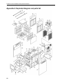
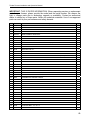
with original parts (see Appendix 6: Exploded diagram and parts list). For firing each
load hot to begin a cycle as described above will not cause premature deterioration of the
furnace. However, letting the furnace run with the air control fully open for entire cycles can
cause damage over time. The hotter you run the furnace throughout burn cycles, the more
quickly its components will deteriorate. For that reason, never leave the furnace
unattended while a new load is being fired hot.
5.1.1 Ash removal
Ash should be removed from the firebox every two or three days of full time heating. Do
not let the ash build up in the firebox because it will interfere with proper fire management.
The best time to remove ash is after an overnight fire when the furnace is relatively cool,
but there is still some chimney draft to draw the ash dust into the furnace and prevent it
from coming into the room.
After ashes have been removed from the furnace and placed in a tightly covered metal
container, they should be taken outside immediately. The closed container of ashes should
be placed on a non-combustible floor or on the ground well away from all combustible
materials pending final disposal. Ashes normally contain some live charcoal that can stay
hot for several days. If the ashes are disposed of by burial in soil or otherwise locally
dispersed, they should be retained in the closed container until all cinders have thoroughly
cooled. Other waste shall not be placed in this container.
NEVER STORE ASHES INDOORS OR IN A NON-METALIC CONTAINER OR ON A
WOODEN DECK. ALWAYS LEAVE THE CONTAINER ON A NON COMBUSTIBLE
FLOOR.
5.1.2 Cleaning door glass
Under normal conditions, your door glass should stay relatively clear. If your firewood is
dry enough and you follow the operating instructions in this manual, a whitish, dusty
deposit will form on the inside of the glass after a week or so of use. This is normal and
can be easily removed when the furnace is cool by wiping with a damp cloth or paper towel
and then drying. Never try to clean the glass when the furnace is hot.
In spring and fall the furnace will cycle less often. You may see some light brown stains
forming, especially at the lower corners of the glass. This indicates that the combustion
has been incomplete and some of the smoke has condensed on the glass. When the
weather is mild, you may find that letting the fire go out is better than trying to maintain a
continuous fire. Use the technique described above for building a fire to take the chill off
the house.
25
Tundra Furnace Installation and Operation Manual
If you do get brown stains on the glass you can remove them with special cleaners for
wood furnace glass doors. Do not use abrasives to clean your furnace’s door glass.
The deposits that form on the glass are the best indication of the quality of your fuel and
how well you are doing in operating the furnace. Your goal should be clear glass with no
brown stains. If you continue to see brown stains on the glass, something about your fuel
and operating procedure needs to be changed. Stains on the glass indicate incomplete
combustion of the wood, which also means more smoke emissions and faster formation of
creosote in the chimney.
If you see brown streaks coming from the edge of the glass, it is time to replace the gasket
around the glass. Visit your furnace retailer to get the self-adhesive glass gasket and
follow the Section 5.1.4: Replacement of the glass and gaskets instructions for
installation.
Check the glass regularly to detect any crack or damage. Replace damaged glass
immediately; do not use the furnace with a broken glass.
5.1.3 Door adjustment
In order for your furnace to burn at its best efficiency, the door must provide a perfect seal
with the firebox. Therefore, the gasket should be inspected periodically making sure to
obtain an air tight fit. Air tightness can be improved with a simple latch mechanism
adjustment. If the adjustment is not sufficient, replace the door gasket with a new one.
Door adjustment procedure
1. Unscrew the locking pin (B) and nut (A) from the door (see image below).
2. To increase the pressure of the door on the gasket, turn the handle. Counter-clockwise,
to reduce the pressure of the door on the cord, turn the handle clockwise to clockwise.
3. Finally, screw-in the locking pin (B) about 1/4 "deep and make sure you lock it with the
nut (A).
26
Tundra Furnace Installation and Operation Manual
5.1.4 Replacement of the glass and gaskets
After a year or more of use, the gasket of the door will compress and become hard which
can allow air to pass. You can check the air tightness of your door gasket by closing and
locking the door on a piece of paper. Check all around the door. If the paper slides easily
anywhere, it is time to replace the gasket.
Use a good quality gasket that you can purchase from your dealer. The correct size and
density of the gasket are important to ensure a good seal.
Prior of removing the defective glass, you need to remove the door gasket. Inspect the
door gasket before it is reinstalled to make sure it is in good condition. We suggest
replacing the door and glass gasket at the same time as their level of wear over time is
similar.
For the following steps, wearing gloves and safety glasses are recommended for handling
seals can irritate the skin and the glass can be sharp.
To replace the door gasket, use the steps 1 to 3 and 10 outlined below;
To replace the glass, use the steps 1 to 6 and 9 to 10 outlined below;
To replace the glass gasket, use the steps 1 to 10 outlined below;
27
Tundra Furnace Installation and Operation Manual
1. Remove the door (F) and place it on a stable work surface, handle down.
2. Using pliers, remove the door gasket (A).
3. Using a scraper or a small flat screwdriver, remove the adhesive left in the gasket
grove in the door then clean the surface using a commercial vacuum.
4. Use a Phillips screwdriver or a power drill to remove the screws (B) that holds the glass
retainer (C).
5. Remove the glass frame (D)
6. Remove the glass (E) (or pieces of glass if it is damaged) and clean the inside of the
door frame.
7. Remove the old glass gasket.
8. Install the new gasket on the glass. Remove a part of the paper covering the gasket
adhesive. Center the gasket on the edge of the glass so that when folded and glued,
the gasket is equal on both sides. Do not stretch the gasket during installation. Remove
a majority of the paper, turn the glass to facilitate and complete the installation of the
gasket. When you return to the starting point, cut the gasket so that the ends overlap
by about ½ inch.
9. Install the glass (E) and glass frame (D) and centering it in the frame of the door and
install the glass retainer frame (D) and glass retainers © taking care not to over tighten
the screws (B). Note that the two main causes of glass breakage are unequal position
in the door and screws too tight.
10. Install the new door gasket (A). To do this, use about ¼ inch. (6mm) of adhesive to the
bottom of the groove that holds the gasket in the door. Then lay the new gasket
starting from the center of the hinge side and taking care not to stretch the gasket
during installation. Leave about ½ inch of gasket exceed the frame of the door. Once
jointed, push the fibers protruding towards the inside of the groove in the adhesive.
Install the door and let dry for 24 hours before using the furnace.
28
Tundra Furnace Installation and Operation Manual
Do not abuse the glass door by striking or slamming shut. Do not use the furnace if the
glass is broken. To change the glass, perform the same operation described above.
5.1.5 Cleaning and painting the furnace
Do not attempt to clean or paint the furnace when the unit is hot. Painted surfaces
can be wiped down with a damp cloth. Plated or enameled surfaces may be scratched by
abrasive cleaners. To maintain the finish at its original brilliance, use only a damp soft cloth
to clean plated or enameled surfaces.
If the paint becomes scratched or damaged, you can give your wood furnace a brand new
look by repainting it with heat-resistant or enamel finish paint. Before painting, roughen the
surface with fine sand paper, wipe it down to remove dust, and apply two thin coats of
paint. For best results, use the same paint that was originally used on the furnace, which is
available in spray cans. See your dealer for details.
5.1.6 Heat exchangers care
Heat exchangers must be cleaned thoroughly at the end of every heating season. During
summer, the air in basements is damper and with minimal air circulation within the furnace,
it can mix with creosote and/or sooth deposits in the exchangers to form an acid that could
accelerate the corrosion process and induce premature decay of the steel. Corrosion
damages are not covered under warranty.
29
Tundra Furnace Installation and Operation Manual
Smoke pipe and exchangers must be inspected regularly during the heating season.
Access to the exchangers is easy and does not require tools;
1. Unscrew the wing nut (B) and remove the washer (C) on the exchanger access door.
2. Move the baffle of the combustion chamber forward.
30
Tundra Furnace Installation and Operation Manual
3. Use the tool provided, clean the three exchanger pipes.
4. Dirt in the lateral exchangers fall into the combustion chamber at the rear.
31
Tundra Furnace Installation and Operation Manual
5. Dirt in the central exchanger will be removed from the front or the rear of the furnace. If
you remove dirt from the central exchange to the back of the furnace, remove the black
pipe connector in order to dispose of the dirt.
6. Then, check that the baffle is clear of ash and reposition it in its original position
towards the back of the combustion chamber.
32
Tundra Furnace Installation and Operation Manual
7. Close the exchanger access door and secure it using the washer (C) and wing nut (B).
8. If you have performed maintenance from the back part of the furnace, reinstall the
black pipe connector and secure it with three screws.
5.2 Chimney and chimney connector maintenance
5.2.1 Why chimney cleaning is necessary
Wood smoke can condense inside the chimney connector and chimney, forming a
combustible deposit called creosote. If creosote is allowed to build up in the venting
system it can ignite when a hot fire is burned in the furnace and a very hot fire can
progress to the top of the chimney. Severe chimney fires can damage even the best
chimneys. Smouldering, smoky fires can quickly cause a thick layer of creosote to form.
When you avoid smouldering so the exhaust from the chimney is mostly clear, creosote
builds up more slowly. Your new furnace has the right characteristics to help you to burn
clean fires with little or no smoke, resulting in less creosote in the chimney.
5.2.2 How often should you clean the chimney?
It is not possible to predict how much or how quickly creosote will form in your chimney. It
is important, therefore, to check the build-up in your chimney monthly when getting used to
the new furnace until you determine the rate of creosote formation. Even if creosote forms
slowly in your system, the chimney should be cleaned and inspected at least once each
year.
Contact your local municipal or provincial fire authority for information on how to handle a
chimney fire. Have a clearly understood plan to handle a chimney fire.
33
Tundra Furnace Installation and Operation Manual
WARNING: IT IS RECOMMENDED TO CLEAN THE HEAT EXCHANGERS
THOROUGHLY AT THE END OF SEASON IN ORDER TO PREVENT CORROSION).
5.2.3 Cleaning the chimney
Chimney cleaning can be a difficult and dangerous job. If you don’t have experience
cleaning chimneys, you might want to hire a professional chimney sweep to clean and
inspect the system for the first time. After having seen the cleaning process, you can
decide if it is a job you would like to take on.
The most common equipment used are fibreglass rods with threaded fittings and stiff
plastic brushes. The brush is forced up and down inside the chimney flue to scrub off the
creosote.
The chimney connector assembly should always be cleaned at the same time the chimney
is cleaned.
CAUTION: Operation of your furnace without the baffle may cause unsafe and hazardous
temperature conditions and will void the warranty. NOTE: Before installing the firebrick,
check to ensure that none are broken or damaged in any way. If so, have the damaged
ones replaced. Check the firebrick for damage at least annually and replace any broken or
damaged ones with new ones. Inspection and cleaning of the chimney is facilitated by the
removable baffle.
5.3 Smoke pipe inspection
The smoke pipe must be inspected regularly during the heating season.
The pipe must be examined carefully to detect any defect or damage.
The pipe can be reassembled if no defect is detected and defective pipe must be
replaced immediately.
INSPECT FLUE PIPES, FLUE PIPE JOINTS, AND FLUE PIPE SEALS REGULARLY
TO ENSURE THAT SMOKE AND FLUE GASES ARE NOT DRAWN INTO, AND
CIRCULATED BY, THE AIR-CIRCULATION SYSTEM
5.4 Blower motor maintenance
Periodic cleaning of the fan housing and louvers as well as fan and fan blades using a
vacuum cleaner is necessary in order not to affect performance and cause overheating of
the latter.
34
Tundra Furnace Installation and Operation Manual
PART B - INSTALLATION
6 Safety information
6.1 Summary of installation cautions and warnings
THE INFORMATION GIVEN ON THE CERTIFICATION LABEL AFFIXED TO THE
APPLIANCE ALWAYS OVERRIDES THE INFORMATION PUBLISHED, IN ANY
OTHER MEDIA (OWNER’S MANUAL, CATALOGUES, FLYERS, MAGAZINES
AND/OR WEB SITES).
MIXING OF APPLIANCE COMPONENTS FROM DIFFERENT SOURCES OR
MODIFYING COMPONENTS MAY RESULT IN HAZARDOUS CONDTIONS. WHERE
ANY SUCH CHANGES ARE PLANNED, FURNACE BUILDER INTERNATIONAL
INC. SHOULD BE CONTACTED IN ADVANCE.
ANY MODIFICATION OF THE APPLIANCE THAT HAS NOT BEEN APPROVED IN
WRITING BY THE TESTING AUTHORITY VIOLATES CSA B365 (CANADA), AND
NFPA 90B (USA).
CONNECT THIS FURNACE ONLY TO A LISTED UL 103 HT OR ULC S629
FACTORY-BUILT CHIMNEY FOR USE WITH SOLID FUEL OR TO A LINED
MASONRY CHIMNEY CONFORMING TO NATIONAL AND LOCAL BUILDING
CODES.
IF REQUIRED, A SUPPLY OF COMBUSTION AIR SHALL BE PROVIDED TO THE
ROOM OR SPACE.
DO NOT CONNECT THIS UNIT TO A CHIMNEY FLUE SERVING ANOTHER
APPLIANCE.
DO NOT INSTALL IN A MOBILE HOME
6.2 Regulations covering furnace installation
WARNING
RESPECT THE LOCAL CODES (WHEN IN DOUBT, CONSULT YOUR LOCAL
DEALER).
Before installation, please read the instructions carefully and make sure you
understand them:
Installation must be made in accordance with the CSA B365 « Installation code for solidfuel-burning appliances and equipment » standard in Canada and NFPA 90B « Standard
for the installation of warm air heating and air conditioning system » in the United States.
Moreover, for all electrical connection, the Canadian standard CSA C22.1 « Canadian
35
Tundra Furnace Installation and Operation Manual
electrical code » and in the United-States NFPA 70 standard « National Electrical Code »
must be followed.
Inspect the furnace to make sure that nothing has been damaged in the shipping. Pull out
the instruction manual from the firebox of the furnace and the accessories from the flue
pipe and/or exchangers.
The blower speed must conform to the recommendations of the Warm Air Heating and
Air Conditioning National Association and should respect the static pressure ranges in
the warm air plenum of the furnace (see section 2.1.2, General technical data).
6.3 Connecting pipe, manual and barometric damper
WARNING:
DO NOT INSTALL A MANUAL DAMPER ON THIS FURNACE.
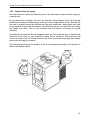
Here are some tips for proper installation:
The TUNDRA furnace must be connected to a factory built chimney as per UL 103 HT or
ULC S629 for wood heating appliances, we recommend that the connecting pipe and
chimney have a 6" inside diameter. The minimum draft required at all times is -0.04 in.
W.C. but the furnace will perform at its best with a draft of -0.06 in. W.C.
Slightly higher draft is acceptable and a barometric draft control is not normally required on
this unit but a barometric control must be installed to control excessive draft (more than 0.08 in. W.C.).
If a barometric damper must be installed, it must be adjusted to the maximum draft
measured at the output of the furnace to -0.06 " W.C. Please note that a draft greater than
-0.08 in. W.C. could produce runaway (uncontrolled fire) of the furnace. The minimum draft
required is -0.04 " W.C. in the exhaust pipe.
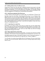
All the exhaust pipe joints must be secured with three screws.
1. Make sure that each screw goes through the inner wall of both connectors (male and
female). See pictures below showing a male-female coupling.
36
Tundra Furnace Installation and Operation Manual
CAUSES
RESTRICTION
PROPER INSTALLATION
IMPROPER INSTALLATION
2. A minimum rise of ¼” per horizontal foot must be respected.
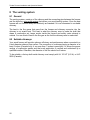
6.4 Chimney and draft
This furnace must be connected to a chimney certified for wood burning heating
appliances; a 6” connector and chimney is mandatory. The barometric damper must be
adjusted so that the maximum draft measured at the furnace outlet is limited to -0.06 in.
w.c. However, the minimum draft to be respected at all times is -0.04 in. w.c. in the
evacuation pipe.
If the chimney draft exceeds -0.06" w.c, a barometric draft control should be installed on
the smoke pipe. Never install a manual damper.
37
Tundra Furnace Installation and Operation Manual
The barometric control must be adjusted so that the maximum draft measured at the
furnace outlet does not exceed -0.06" w.c. Please note that a draft exceeding -0.06" w.c.
will reduce the efficiency and could produce an uncontrollable fire. On the other hand,
the minimum draft required is 0.04" w.c. in the evacuation pipe on the wood side, no
matter what type of furnace.
CAUTION: BEFORE THE CONNECTOR PIPES ARE INSTALLED, MAKE SURE THAT
THE EXHAUST PIPE AND / OR THE EXCHANGERS OF THE FURNACE ARE FREE OF
ALL ITEMS.
WARNING: AN EXCESSIVE DRAFT MAY CAUSE OVERHEATING AND MAKE THE
CONTROL OF THE FIRE DIFFICULT.
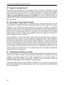
6.5 Combustion air
When the furnace and the chimney are completely cold, it may be necessary to provide
fresh air by opening a door or a window for a few minutes while lighting the fire.
Take note that a house constructed or renovated in order to be airtight may lack the
volume of fresh air necessary for the proper combustion of a solid-fuel heating appliance.
In such a case, when starting up the fire, do not operate appliances that evacuate air
outside the house, such as:
Range hood
Air exchanger
Clothes dryer
Bathroom fan
Ventilated central vacuum system
Exhaust fans that are in a fuel storage room should be installed so as not to create
negative pressure in the room where the solid fuel appliance is located.
A fresh air supply may be necessary to prevent solid fuel units from rejecting products of
combustion into the house. The indications used to determine if an additional fresh air
supply is necessary are not appropriate for all the situations. When in doubt, it is
recommended to install a fresh air supply.
A fresh air supply may be needed if:
-
Solid fuel units present anomalies, such as irregular draft, smoke return, bad
combustion, and/or reversed draft (whether there is combustion or not);
-
Existing solid fuel units such as a stove or fireplace release odours, heat badly, cause
smoke returns, or reversed draft (whether there is combustion or not );
38
Tundra Furnace Installation and Operation Manual
-
The opening of a window, even slightly, in calm weather (windless), eliminates every
problem mentioned above ;
-
The house is equipped with a tight vapour barrier and adjusted windows, and/or is
equipped with an interior air mechanical evacuation device ;
-
There is excessive condensation on the windows in winter; and
-
The house is equipped with a ventilation system.
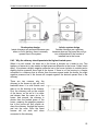
If, according to these symptoms or other similar ones, there is insufficient combustion air, it
is necessary to ensure an additional combustion air supply.
Additional combustion air can be provided following the following methods, provided that
they satisfy chapter 4 of the CSA B365 standard for Canada:
-
Direct connection: solid fuel units can be connected directly to a source of new
combustion air only if they are certified for this kind of installation, which must respect
the manufacturer’s instructions.
-
Indirect method: new combustion air can be brought into a pipe located within
approximately 300mm (12 inches) of the unit. If the pipe is too close to the furnace, it
may interfere with its operation.
-
Mechanical ventilation system: if the house is equipped with a ventilation system (air
exchanger or heat recovery), the ventilation system may provide sufficient auxiliary air
to the solid fuel unit. Otherwise, the owner should be informed that the ventilation
system may have to be rebalanced by a ventilation technician after the installation of
the solid fuel unit.
WARNING: SUFFICIENT COMBUSTION AIR MUST BE AVAILABLE AT ALL TIMES;
LACK OF COMBUSTION AIR CONSTITUTES A DANGER.
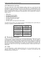
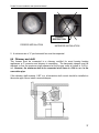
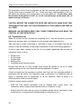
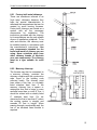
NOTE:
It is recommended to install an outside
air inlet with a diameter of at least 4
inches in the room where the heating
appliance is installed (see drawing next
page). It is preferable to choose a wall
which is not exposed to dominant winds,
depending on the conditions surrounding
your house.
INSULATED PIPE
AIR SUPPLY
AIR INLET
EXTERIOR WALL
39
Tundra Furnace Installation and Operation Manual
6.6 Filter
Even though this furnace is not equipped with a filter, we strongly recommend the
installation of the optional filter kit, sold separately. See Appendix 2: Optional Filter
(AC01390).
N.B.: THE OWNER OF THE FURNACE IS RESPONSIBLE FOR THE ROOM’S AIR
QUALITY IN CASE OF NEGATIVE PRESSURE OR TEMPORARY NEGATIVE
PRESSURE.
7 Setting up the unit and clearances
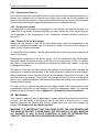
7.1 Unit location
The furnace must be installed where outside air supply will be sufficient for proper
combustion. In airtight houses, it might be necessary to install an outside air inlet (see
details in Section 6.5, Combustion air.)
The furnace must be positioned so that the connector is as short as possible. Minimize the
use of 90o elbows and horizontal lengths.
The owner must ensure a proper installation to allow a safe operation of the
appliance.
7.2 Location of the certification label
Since the information given on the certification label affixed to the appliance always
overrides the information published, in any other media (owner’s manual, catalogues,
flyers, magazines and/or web sites) it is important to refer to it in order to have a safe and
compliant installation. In addition, you will find information about your furnace (model,
serial number, etc.). You can find the certification label on the back of the furnace.
7.3 Clearances to combustible material
The clearances shown in this section have been determined by test according to
procedures set out in safety standards CSA B366.1 (Canada) and UL 391 (U.S.A.). When
the furnace is installed so that its surfaces are at or beyond the minimum clearances
specified, combustible surfaces will not overheat under normal and even abnormal
operating conditions.
No part of the furnace or flue pipe may be located closer to combustibles than the
minimum clearance figures given.
N.B.: THIS APPLIANCE MUST BE INSTALLED IN ACCORDANCE WITH THE
INSTRUCTIONS ON THE CERTIFICATION LABEL APPLIED ON THE UNIT.
40
Tundra Furnace Installation and Operation Manual
41
Tundra Furnace Installation and Operation Manual
Clearances with a ceiling height (L) of 72" (193 cm)
A
B
C
D
E
F
G
H
CLEARANCES
(SINGLE WALL PIPE)
CANADA
USA
24’’ (610 mm)
24’’ (610 mm)
18’’ (457 mm)
18’’ (457 mm)
12’’ (305 mm) min.
12’’ (305 mm) min.
72’’ (193cm)
72’’ (193cm)
2’’ (50 mm)
2’’ (50 mm)
1’’ (25 mm)
1’’ (25 mm)
72’’ (193cm)
72’’ (193cm)
11" (280 mm)
11" (280 mm)
7.4 Floor protector
Your furnace is designed to prevent the floor from overheating. However, it should be
placed on a non-combustible surface to protect the floor of the hot embers that might fall
from the furnace during loading and maintenance. There are differences between the floor
protection for Canada and the U.S., as shown in the Table and Figure below.
42
Tundra Furnace Installation and Operation Manual
FLOOR PROTECTION*
A
B
C
D
E
CANADA
18" (457 mm)
From door opening
N/A (É-U. seulement)
8" (203 mm)
8" (203 mm) – Note 1
N/A (É-U. only)
USA
16" (406 mm)
From door opening
8" (203 mm)
N/A (Canada only)
N/A (Canada only)
Note 2
*Steel with a minimum thickness of 0.015" (0.38 mm) or ceramic tiles sealed together
with grout. No protection is required if the unit is installed on a non-combustible floor
(ex: concrete).
Note 1: The floor protection at the back of the furnace is limited to the furnace’s
required clearance if such clearance is smaller than 8 inches (203 mm).
Note 2: Only required under the horizontal section of the connector. Must exceed each
side of the connector by at least 2 inches (51 mm).
43
Tundra Furnace Installation and Operation Manual
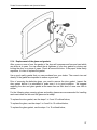
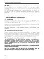
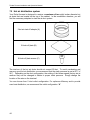
7.5 Hot air distribution system
Your Drolet furnace is designed to receive a maximum of two eight inches diameter hot
air ducts that are located on the top of the cabinet. In the combustion chamber, you will
find the necessary adapters to start the air duct system.
2 hot air start-off adapter (A)
2 block-off plate (B)
8 block-off plate screws (C)
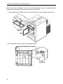
The total run of the hot air ducts should not exceed 50 feet. To avoid overheating and
assure a good hot air distribution, we recommend that the static pressure be set at 0,2’’ of
W.C.. Depending on the duct configuration, the setting of the blower speed (factory set at
medium low) can be changed to obtain to proper static pressure. Simply change the
location of the wire on the terminal.
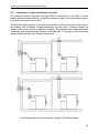
You can choose from 2 duct outlet configuration. For optimum efficiency and to provide
even heat distribution, we recommend the outlet configuration “A”.
44
Tundra Furnace Installation and Operation Manual
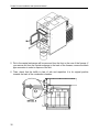
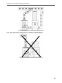
Configuration A (preferred)
Configuration B (acceptable)
Configuration C (NOT ALLOWED)
Configuration D (NOT ALLOWED)
45
Tundra Furnace Installation and Operation Manual
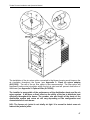
The first vertical start-off pipe should be no less than 12 inch. The minimum clearance to
combustible material of the first 72 inch horizontal duct run is 2 and 1 inch for additional
horizontal length. See image in Section 7.3.
Hot air start-off adapter and block-off plate Installation:
Warning: Wear gloves to perform the following steps since edges of adapters and
plates may be sharp.
Once the hot air outlet configuration has been chosen, install the start-off adapters and the
block-off.
1. Cut a notch in the flange of both adapter A and slightly fold down one side of the flange
to facilitate installation as shown below.
2. Align the notch previously made on the adapter (A) with the one of the selected hot air
outlet on the top of the furnace. Insert the flange under the furnace top, then turn the
adapter until the flange is completely inserted and rotates freely. Repeat the above
procedure for the second adapter.
3. Using the provided screws (C), install the block-off plates (B) on the 2 remaining hot air
outlets.
46
Tundra Furnace Installation and Operation Manual
The installation of the air return option connected to the blower housing would improve the
air circulation throughout the house (see Appendix 3: Fresh air return adapter
(AC01392)). The use of the air filter option is also recommended. The filter option will
significantly reduce dust circulation within the hot air duct and will prevent obstruction of
the blower (see Appendix 2: Optional filter (AC01390)).
The installer is responsible of the performance of the distribution ducts and the air
return system. It will have a direct effect on the ability of the fan to distribute heat
efficiently throughout the house. The number, size and length of the ducts of the
distribution system and return air will vary depending on the configuration and
characteristics of each house.
N.B.: The furnace air jacket is not totally air tight. It is normal to detect some air
leaks at the jacket’s joints.
47
Tundra Furnace Installation and Operation Manual
7.5.1 Authorized configurations in Canada and United States
7.5.2 Authorized configurations in United States only
The installation of this furnace in parallel with another furnace that uses the same system
of hot air ducts are not permitted in Canada. This type of installation is only allowed in
the United States only. Ideally, the maximum input of the existing gas, oil or electric
furnace should be equal to or higher than the wood furnace. It is mandatory to meet the
minimum clearances between the hot air ducts and combustible materials like the wood
furnace was installed alone. Necessary adjustments should be made to the furnace or hot
air ducts to maintain a static pressure of 0.20 PO.CE. To prevent a return air in either of
the two furnaces, a non-return ("back flow damper") damper must be installed. The nonreturn damper is necessary to ensure that the hot air flow through the house and does not
return through the plenum of the other furnace. Depending on your installation (see
examples below), a damper may be installed in each plenum.
48
Tundra Furnace Installation and Operation Manual
7.5.3 Non-authorized configuration, Canada and United States
49
Tundra Furnace Installation and Operation Manual
8 The venting system
8.1 General
The venting system, made up of the chimney and the connecting pipe between the furnace
and the chimney, acts as the engine that drives your wood heating system. Even the best
furnace will not function safely and efficiently as intended if it is not connected to a suitable
chimney.
The heat in the flue gases that pass from the furnace and chimney connector into the
chimney is not waste heat. This heat is what the chimney uses to make the draft that
draws in combustion air, keeps smoke inside the furnace and safely vents exhaust to
outside. You can think of heat in the flue gas as the fuel the chimney uses to make draft.
8.2 Suitable chimneys
Your wood furnace will provide optimum efficiency and performance when connected to a
6-inch diameter chimney flue system. The connection to a chimney having a diameter of at
least 5 inches (Canada only) or no more than 7 inches is permitted, if it allows the proper
venting of combustion gases and that such application is verified and authorized by a
qualified installer. Otherwise, the diameter of the flue should be 6 inches.
To be suitable, a factory-built metal chimney must comply with UL 103 HT (U.S.A.) or ULC
S629 (Canada).
50
Tundra Furnace Installation and Operation Manual
8.2.1 Factory-built metal chimneys
These are sometimes referred to as
‘high temp’ chimneys because they
have the special characteristics to
withstand the temperatures that can be
created by wood burning furnaces.
Factory-built chimneys are tested as a
system with all the necessary
components for installation. The
instructions provided with the chimney
by its manufacturer are the only reliable
source of installation guidelines. To be
safe and effective, the chimney must
be installed exactly in accordance with
the manufacturer’s instructions. Use
only components intended for the
brand and model of chimney you are
using. Never substitute parts from
other chimney brands or fabricate
your own components. The chimney
must be a type suitable for solid
fuel.
8.2.2 Masonry chimneys
The furnace may also be connected to
a masonry chimney, provided the
chimney complies with the construction
rules found in the building code
enforced locally. The chimney must
have either a clay liner or a suitably
listed stainless steel liner. If the
masonry chimney has a square or
rectangular liner that is larger in cross
sectional area than a round 6” flue, it
should be relined with a suitably listed
6” stainless steel liner. Do not
downsize the flue to less than 6” unless
the venting system is straight and
exceeds 25 feet in height. When
passing through a combustible wall, the
use of an insulated listed thimble is
required.
51
Tundra Furnace Installation and Operation Manual
8.3 Minimum chimney height
The top of the chimney should be
tall enough to be above the air
turbulence caused when wind
blows against the house and its
roof. The chimney must extend at
least 1 m (3 ft.) above the highest
point of contact with the roof, and
at least 60 cm (2 ft.) higher than
any roof line or obstacle within a
horizontal distance of 3 m (10 ft.).
8.4 Relationship between the chimney and the house
Because the venting system is the engine that drives the wood heating system, it must
have the right characteristics. The signs of bad system design are cold back drafting when
there is no fire in the furnace, slow kindling of new fires, and smoke roll-out when the door
is opened for loading. There are two guidelines to follow. First, the chimney should be
installed up through the heated space of the house, not out and up an outside wall.
Second, the chimney should penetrate the top of the building at or near the highest heated
space.
8.4.1 Why inside chimneys are preferred
Venting systems that rise straight up from the furnace flue collar provide the best
performance. Chimneys that rise inside the warm space of the house tend to provide a
small amount of draft even when there is no fire burning. This means that when you light a
fire, the initial smoke goes up the chimney and strong draft builds quickly as the chimney
flue warms up. Although they are common in North America, chimneys that exit a house
wall and run up outside can cause problems.
52
Tundra Furnace Installation and Operation Manual
Good system design
Inside chimneys are preferred because even
when no fire is burning, there is normally
upward flow in the system.
Inferior system design
Outside chimneys are a problem
because when no fire burns they will go
into cold backdraft if the furnace is
installed low in the house.
8.4.2 Why the chimney should penetrate the highest heated space
When it is cold outside, the warm air in the house is buoyant so it tends to rise. This
tendency of warm air to rise creates a slight pressure difference in the house. Called ‘stack
effect’, it produces a slightly negative pressure low in the house (relative to outside) and a
slightly positive pressure zone high in the house. If there is no fire burning in a heater
connected to a chimney that is shorter than the warm space inside the house, the slight
negative pressure low in the house will compete against the desired upward flow in the
chimney.
There are two reasons why the
chimney in the house at right will cold
backdraft when it is cold outside and
there is no fire burning in the furnace.
First, the chimney runs up the outside
of the house, so the air in it is colder
and denser than the warm air in the
house. And second, the chimney is
shorter than the heated space of the
house, meaning the negative pressure
low in the house will pull outside air
down the chimney, through the furnace
and into the room. Even the finest
furnace will not work well when
connected to this chimney.
53
Tundra Furnace Installation and Operation Manual
8.5 Supply of combustion air
In Canada, wood furnaces are not required to have a supply of combustion air from
outdoors because research has shown that these supplies do not give protection against
house depressurization and may fail to supply combustion air during windy weather.
However, to protect against the risk of smoke spillage due to house depressurization, a
carbon monoxide (CO) detector/alarm is required in the room in which the furnace is
installed. The CO detector will provide warning if for any reason the wood furnace fails to
function correctly.
8.6 Air supply in conventional houses
The safest and most reliable supply of combustion air for your wood furnace is from the
room in which it is installed. Room air is already preheated so it will not chill the fire, and its
availability is not affected by wind pressures on the house. Contrary to commonly
expressed concerns, almost all tightly-sealed new houses have enough natural leakage to
provide the small amount of air needed by the furnace. The only case in which the wood
furnace may not have adequate access to combustion air is if the operation of a powerful
exhaust device (such as a kitchen range exhaust) causes the pressure in the house to
become negative relative to outdoors.
Some jurisdictions in the United States require that wood furnaces have a supply of
combustion air from outdoors. If you do install an air supply through the wall of the house,
be aware that its pressure can be affected during windy weather. If you notice changes in
wood furnace performance in windy weather, and in particular if smoke puffs from the
furnace, you should disconnect the outdoor air duct from the furnace and remove the duct.
In some windy conditions, negative pressure at the duct weatherhood outside the house
wall may draw hot exhaust gases from the furnace backwards through the duct to
outdoors. Check the outdoor air duct for soot deposits when the full system is cleaned and
inspected at least once each year.
8.7 Installing the chimney connector
The chimney connector is the single or double wall pipe installed between the furnace flue
collar and the chimney breech. Single wall pipe components are available from most
hardware and building supply stores. These components are not usually tested to a
particular standard and certified as compliant. Therefore, a list of rules found in solid fuel
installation codes applies to the installation of single wall pipe.
Double wall chimney connectors are tested and certified. The rules for double wall pipe are
found in the manufacturer’s installation instructions. These rules will be very different than
those for single wall.
54
Tundra Furnace Installation and Operation Manual
8.7.1 Installation of single wall chimney connector
The chimney connector assembly has been called ‘the weak link’ in the safety of wood
heating systems because failure to install the connector properly (which has been common
in the past) can result in house fires.
The best flue pipe assembly is one that rises straight up from the furnace to the base of
the chimney with no elbows. Straight assemblies are less likely to cause problems like
smoke roll-out when the door is opened for loading. They are also more stable and easier
to maintain than assemblies with elbows. Horizontal runs of flue pipe should be avoided
where possible because they reduce chimney draft.
Use 45 degree elbows where possible, instead of 90 degree elbows.
55
Tundra Furnace Installation and Operation Manual
The rules below are based on those found in the CSA B365 installation code. Please
carefully follow these installation instruction rules, or those enforced where you live.
•
•
•
•
•
•
•
•
•
•
•
•
•
•
•
•
Maximum overall length of straight pipe: 3 m (10 ft.) including elbows.
Minimum clearance from combustible material: 450 mm (18 in.). The minimum
clearance may be reduced by 50 percent to 225 mm (9 in.) if suitable shielding is
installed either on the pipe or on the combustible surface.
The assembly should be as short and direct as possible between the furnace and
chimney. The use of two 45 degree elbows is often preferable to a single 90 degree
elbow because less turbulence is created in the exhaust flow and they result in less
horizontal run.
Maximum number of 90-degree elbows: 2.
Maximum unsupported horizontal length: 1 m (3 feet).
Galvanized flue pipes must not be used because the coatings vaporize at high
temperatures and release dangerous gases. Use black painted flue pipes.
Flue pipes must be at least 24 gauge in thickness.
Flue pipe joints should overlap 30 mm (1 1/4 in.)
Each joint in the assembly must be fastened with at least three screws.
The assembly must have allowance for expansion: elbows in assemblies allow for
expansion; straight assemblies should include an inspection wrap with one end
unfastened, or a telescopic section.
Minimum upward slope towards the chimney: 20 mm/m (1/4 in/ft.).
One end of the assembly must be securely fastened to the flue collar with 3 sheet
metal screws and the other end securely fastened to the chimney.
There must be provision for cleaning of the pipes, either through a clean out or by
removal of the pipe assembly. Removal of the assembly should not require that the
furnace be moved.
The male ends of the sections must be oriented towards the appliance so that falling
dust and condensation stay inside the pipe.
A flue pipe must never pass through a combustible floor or ceiling or through an attic,
roof space, closet or concealed space.
Where passage through a wall or partition of combustible construction is desired, the
installation shall conform to CAN/CSA-B365, Installation Code for Solid-Fuel-Burning
Appliances and Equipment.
The ideal flue pipe assembly is one that rises straight up from the appliance flue collar and
directly into the chimney with no elbows. A straight up connector assembly needs either a
telescopic length or an inspection wrap (pipe coupler) to allow it to be assembled and
disassembled without moving the furnace.
A straight flue pipe assembly offers the least restriction to gas flow and results in stronger
draft. Straight assemblies also need less maintenance because there are no corners to
collect creosote.
The chimney connector must be in good condition.
56
Tundra Furnace Installation and Operation Manual
9 Electrical connections and controls
The TUNDRA furnace is fully assembled at the factory and no electrical connection is
required other than plugging the power cord into an outlet.
9.1 Wiring diagram
The following instructions do not replace those of the local code.
Installation and verification of this appliance must be done by a qualified service
man.
All wiring from the service panel to the heating unit must comply with the electrical code in
force and all local regulations. It is recommended to feed the furnace with its own electrical
circuit of 15 amps at 120 volts with a breaker (see wiring diagram).
WARNING
ONLY USE WIRES SUITABLE FOR 75 °C OR MORE (167 °F).
57
Tundra Furnace Installation and Operation Manual
58
Tundra Furnace Installation and Operation Manual
9.2 Manual or thermostat control
From factory, the opening and closing of the air inlet damper is manually activated by the
means of a switch located at the rear of the furnace. The switch has two positions; opened
and closed.
For added comfort, the installation of an optional wall thermostat is recommended since it
will open the air inlet damper when the room temperature is below the set point of the
thermostat and will close the air inlet damper as the desired temperature is reached (see
Appendix 1: Optional Thermostat Installation).
If the heat sensors detect any overheating in the air jacket of the furnace, the air inlet
damper will close automatically regardless of the type of control used.
9.3 Fan control
The fan is activated when the air jacket temperature of the furnace reaches 140 °F and
stops when it drops below 120 °F. If the air jacket temperature exceeds 160 °F, the air inlet
damper closes and the fan will continues to blow until temperature returns below 120 °F at
which point the air inlet control will open again.
To optimize the heat distribution efficiency of the furnace, the blower of the TUNDRA was
set at the factory on speed 2 (medium-low). If needed, it is possible to change the fan
speed by moving the black wire coming from the control box to the desired speed (see
electrical diagram). Make sure the new setting complies with the recommendations of the
National Association of Hot Air Heating and Air Conditioning while respecting the
recommended static pressure.
59
Tundra Furnace Installation and Operation Manual
Debit as function of fan speed
Fan speed
1
2
3
4
60
Static pressure (in. WC)
0.2"
0.2"
0.2"
0.2"
Debit (CFM)
900
1,000
1,200
1,400
Tundra Furnace Installation and Operation Manual
Appendix 1: Optional thermostat installation
Using a thermostat will help you maintain a constant temperature throughout the house. A
fixed wall mounted 24v thermostat is required.
Note: Thermostat manufacturer’s instruction always overrides the information
published in the following section.
Thermostat location
The thermostat must be installed on an inside wall of the house and where it will be the
least affected by affected by air currents from a hot air outlet or cold outside walls. The
thermostat must be installed at a minimum of 55 inches above the floor.
Thermostat wiring
Before installing the thermostat, disconnect the furnace from the outlet. Use a 18 AWG 2
strand wire. Connect the two wires from the thermostat to the terminal at the rear right
side of the furnace. To do this, loosen the two screws in the middle of the terminal bloc and
insert the wires in the terminals. Tighten the two screws. Then open the thermostat
housing and connect the wires following the manufacturer's instructions.
61
Tundra Furnace Installation and Operation Manual
Exemple of thermostat wiring
Connect one wire to "HR" and the other wire to "W". The red jumper can be left in place.
For more information, refer to the manufacturer's instructions.
Use in thermostat mode
To ensure proper operation of the air inlet damper while connected to a thermostat, the
manual control switch must be maintained in the closed position. However, when a
thermostat is connected to the furnace, it is still possible to use the manual control switch
to open the air damper if desired.Even though you chose to control the furnace with a
thermostat it is still possible to use the manual control switch to open the air intake damper
if desired.
62
Tundra Furnace Installation and Operation Manual
Appendix 2: Optional filter (AC01390)
The filter option (part number AC01390) allows filtrating dirt before distribution warm air in
your installation in addition of protecting your blower. This system can be installed on any
side of the blower box located behind the furnace on the most accessible side of your
installation. This option includes the filter, the filter holder, two caps and the screws
necessary for the installation.
Clean and replace filters as often as required.
Note: The operation cost is higher when using a dirty filter.
1 filter holder
2 caps
1 filter (15’’ x 20’’ x 1’’)
WARNING: IT IS NOT RECOMMENDED TO OPERATE THE FURNACE WITHOUT
FILTERS. THIS APPLIES ESPECIALLY TO TEMPORARY HEATING DURING
CONSTRUCTION PERIOD. OPERATING THE FURNACE WITHOUT FILTERS WOULD
ALLOW DUST AND OTHER PARTICLES IN THE AIR TO CIRCULATE FREELY AND
TO PENETRATE INTO THE FAN AND MOTOR CARTERS, CAUSING SOME DEFECTS.
63
Tundra Furnace Installation and Operation Manual
Appendix 3: Fresh air return adapter (AC01392)
The optional air return adapter (AC01392) can be added to the furnace blower box to
increase the efficiency of your system. This option allows you to take in the fresh air from
the rooms connected to the return system and bring it back towards the furnace to be
heated. This option can be installed on either one of the 3 sides of the blower box.
Complete installation instruction can be found in the instruction booklet provided when
purchasing this option.
1 fresh air return adapter
2 caps
1 filter
N.B.: TO ENSURE ADEQUATE STATIC PRESSURE, THE SYSTEM SHOULD BE
BUILT IN A WAY THAT THE VOLUME OF COLD AIR RETURN IS AT LEAST EQUAL
OR SLIGHTLY HIGHER THAN THE VOLUME OF THE HOT AIR DISTRIBUTION.
64
Tundra Furnace Installation and Operation Manual
Appendix 4: Installation of secondary air tubes and baffle
1- Starting with the rear tube, lean and
insert the right end of the secondary air
tube into the rear right channel hole.
Then lift and insert the left end of the
tube into the rear left channel.
2- Align the notch in the left end of the
tube with the key of the left air channel
hole. Using a « Wise grip » hold the
tube and lock it in place by turning the
tube as shown in Detail A. Make sure
the notch reaches the end of the key
way.
3- Repeat step 1 and 2 for the other
secondary air tubes.
4- To remove the tubes use the above
steps in reverse order.
65
Tundra Furnace Installation and Operation Manual
Note that secondary air tubes (A) can be replaced without removing the baffle board (B).
Important Notes:
The air tubes are identified for placement as follows:
66
Model
Type of tube
TUNDRA
Front ► 106 holes of 0.109"
Middle front ► 53 holes of 0.109’’
Middle rear ► 53 holes of 0.109’’
Rear ► 53 holes of 0.109’’
Tundra Furnace Installation and Operation Manual
Appendix 5: Troubleshooting
PROBLEM
CAUSES
SOLUTIONS
Heating inefficient during the first Improper adjustment of the barometric Adjust the damper, minimize the
combustions. Lack of draft.
damper (opened too wide). Chimney smoke pipe length and use 45o
flue restriction (too long. 90o elbows)
elbows.
Furnace burns well, warm air plenum Improper installation of the ducts, low Rearrange the ducting to respect the
is very hot but there is not much heat static press0ure, unbalanced system minimum static pressure of 0.20 in.
coming out in the room.
(too many warm air outlets and not w.c.
enough cold air inlets).
Furnace consumes a lot of wood.
Damper switch left always on. The
thermostat which controls the damper
is continuously activated or is too
close to a source of cold air. Damper
not properly adjusted. House not
insulated enough.
Ash plug and
drawer are not tightly closed. Furnace
too small for the surface to be heated.
Unbalanced ventilation system, very
little heat where the thermostat is
located.
If manually controlled, install a wall
thermostat. Relocate the thermostat.
Rebalance the ventilation system in
order to increase the air flow in the
room where the thermostat is located.
A lot of creosote, moderate heat Wet wood, lack of draft. Barometric Use dry wood. Adjust the barometric
output.
damper
not
properly
adjusted. damper. Clean the chimney, flue pipe
Restriction in the furnace or chimney. and the furnace exchangers.
Furnace heats a lot but the warm air Wet wood or low grade wood. No Use dry wood.
Rearrange
duct does not get hot.
static
pressure.
Unbalanced ventilation system correctly.
ventilation system.
Primary air inlet damper never opens.
Furnace is not plugged-in.or
electrical component is faulty.
the
an Make sure the furnace is plugged-in a
functional power outlet. Test and
replace if necessary, control switch,
thermostat, themodisc and damper
motor.
IMPORTANT NOTE
FOR, INSTALLATION OF A CENTRAL HEATING VENTILATION SYSTEM, IT IS
HIGHLY RECOMMENDED TO CONSULT A HEATING SYSTEM VENTILATION
SPECIALIST.
N.B.: STOVE BUILDER INTERNATIONAL INC. IS NOT RESPONSIBLE FOR POOR
APPLIANCE PERFORMANCES, DUE TO IMPROPER INSTALLATION OF EXHAUST
SYSTEM OR DUCTING.
67
Tundra Furnace Installation and Operation Manual
Appendix 6: Exploded diagram and parts list
68
Tundra Furnace Installation and Operation Manual
IMPORTANT: THIS IS DATED INFORMATION. When requesting service or replacement
parts for your furnace, please provide the model and the serial number. We reserve the
right to change parts due to technology upgrade or availability. Contact an authorized
dealer to obtain any of these parts. Never use substitute materials. Use of non-approved
parts can result in poor performance and safety hazards.
#
Item
Description
Qty
1
30100
BLACK HEX NUT 1/4 - 20
1
2
30128
SOCKET SET SCREW 1/4"-20 X 1 1/4"
1
3
30429
3/8'' CHROME COIL HANDLE
1
4
SE24258
CAST IRON DOOR FRAME WITH HANDLE
1
5
AC09151
REPLACEMENT HANDLE KIT
1
6
PL51351
GLASS RETAINER FRAME BRACKET
4
7
30124
SCREW #8 - 32 X 5/16'' TRUSS QUADREX ZINC
6
8
SE51352
REPLACEMENT GLASS WITH GASKET 10 7/8" X 13 1/8"
1
9
AC06400
BLACK SELF-ADHESIVE GLASS GASKET KIT (6')
1
10
AC06825
GASKET KIT SELF ROUND BLACK 3/4"
1
11
PL51349
GLASS RETAINER FRAME
2
12
30416
WING NUT 3/8"-16
1
13
30210
WASHER 29/32" OD X 3/8" ID ZINC
1
14
SE48054
HEAT EXCHANGER ACCESS DOOR
1
15
AC06000
SILICONE AND 1/2" x 8' BLACK GASKET REPLACEMENT KIT (DOOR)
1
16
30055
HINGE PIN RETAINING RING 5/16" ID X 0.512" OD
2
17
30168
HINGE PIN 5/16 DIA. X 1 1/4" LONG
2
18
PL66021
PRIMARY AIR INLET DAMPER
1
19
PL66058
AIR INLET DAMPER PROTECTION BOX
1
20
PL66012
PRIMARY AIR DEFLECTOR HEAT SHIELD
1
21
PL56276
ASH SHELF
1
22
30060
THREAD-CUTTING SCREW 1/4-20 x 1/2" F HEX STEEL SLOT WASHER C102 ZINC
7
23
30416
WING NUT 3/8"-16
2
24
SE66025
ASH DRAWER
1
25
28061
CHROME ASH DRAWER HANDLE
1
26
SE66009
AIR JACKET FLOOR ASSEMBLY
1
27
PL66032
RIGHT AIR JACKET PANNEL
1
28
PL66052
RIGHT AIR JACKET PANNEL BACKING PLATE
2
29
PL66019
CONVECTION AIR DEFLECTOR
2
30
PL66033
REAR AIR JACKET PANEL
1
31
PL66068
PRIMARY AIR CONTROL ROD
1
32
51000
HONEYWELL 24V DAMPER MOTOR
1
33
44154
THERMODISC 36T 11L160-40
1
34
SE66064
REAR HEAT RING
1
35
VA1150
THERMODISC F-120-10F
1
36
PL66035
BLOWER BOX BASE
1
37
30109
BOLT HEX 1/4 - 20 X 1"
4
38
30536
LEVELING BOLT 1/4 - 20 x 1''
2
39
SE66037
BLOWER ASSEMBLY WITH 1/4 HP MOTOR, DD 4 SPEED 1075/4RPM
1
69
Tundra Furnace Installation and Operation Manual
#
Item
Description
Qty
40
51009
1/4 HP DD-4 SPEED MOTOR 1075/4RPM
1
41
30335
BLOWER ANTI-VIBRATION CUSHION
4
42
PL66037
BLOWER HOUSING BACKET
2
43
44006
ELECTRICAL BOX 4" X 4" X 2 1/8"
1
44
PL66043
BLOWER BOX SURROUND
1
45
PL66042
BLOWER BOX TOP
1
46
30412
BLACK UNIVERSAL SNAP-IN BUSHING
2
47
PL66041
WIRE CHANNEL
1
48
60008
BLACK NYLON BUSHING
1
49
44091
ROCKER SWITCH 2 POSITION MSR-8
1
50
60036
THERMOSTAT TERMINAL
1
51
PL66080
CONTROL HOUSING COVER
1
52
PL66067
CONTROL HOUSING
1
53
60208
TRANSFORMER 120 V/24 V 20 VA
1
54
PL66014
FLUE COLLAR RING
1
55
49438
8'' (203MM) DIAMETER START-OFF ADAPTER
2
56
PL66039
BLOCK-OFF PLATE
2
57
PL66034
TOP AIR JACKET
1
58
PL66031
LEFT AIR JACKET PANNEL
1
59
PL66063
LEFT CONVECTION AIR DEFLECTOR
1
60
21299
FIREBOX BOTTOM INSULATION
1
61
21084
FIREBOX SIDE INSULATION
2
62
21083
FIREBOX BACK INSULATION
1
63
99999
BUILD TO ORDER
1
64
99999
BUILD TO ORDER
2
65
29010
4 1/2" X 9" X 1.25" REFRACTORY BRICK
20
66
29015
4'' x 9'' x 1.25'' REFRACTORY BRICK
7
67
PL36047
4 1/2" X 6 1/2" X 1 1/4" REFRACTORY BRICK
2
68
29000
4'' X 8'' X1.25'' REFRACTORY BRICK
1
69
PL36163
4" X 9'' X 1 5/8'' X 3 5/16'' REFRACTORY BRICK
2
70
PL36164
4 1/2" X 9'' X 1 X 3 1/2'' REFRACTORY BRICK
4
71
SE16059
ASH DUMP PLUG
1
72
PL66062
FRONT SECONDARY AIR TUBE
1
73
PL66061
SECONDARY AIR TUBE
3
74
21196
VERMICULITE BAFFLE 18 3/8'' X 15 1/2'' X 1 1/4''
1
75
SE45656
TUNDRA FURNACE INSTRUCTION MANUAL KIT
1
76
PL48173
POKER
1
77
PL48171
ASH SHOVEL
1
78
PL48170
HEAT EXCHANGER SCRAPER
1
79
AC01390
AIR FILTER SUPPORT WITH FILTER
1
80
21044
CARDBOARD AIR FILTER 20" X 15" X 1"
2
81
AC01392
AIR RETURN HOUSING
1
70
Tundra Furnace Installation and Operation Manual
DROLET LIMITED LIFETIME WARRANTY
The warranty
The warranty of the manufacturer extends only to the original consumer purchaser and is not transferable. A one-time replacement limit applies to all parts benefiting
from a lifetime coverage. The manufacturer shall in no event be responsible for any special, indirect, consequential damages of any nature, which are in excess of the
original purchase price of the product. The manufacturer may, at its discretion, fully discharge all obligations with respect to this warranty by refunding the wholesale
price of any warranted but defective parts. This warranty applies to products purchased after date indicated on the cover page of this document.
Warranty conditions:
The warranty of Drolet heating appliance and its components are subject to the following conditions:
1) Brand new products with proof of purchase only;
2) This warranty applies to normal residential use only;
3) An authorized qualified technician must perform the installation in accordance with the instructions supplied with this product and all local and national building
codes;
4) If a product is found to be defective, the manufacturer will repair or replace such defect;
5) Repair work covered by the warranty, executed at the purchaser’s domicile by an authorized qualified technician requires the prior approval of the manufacturer;
6) Labour cost and repair work to the account of the manufacturer are based on predetermined rate schedule and must not exceed the wholesale price of the
replacement part;
7) All parts and labour costs covered by this warranty are limited according to the table below :
WARRANTY APPLICATION
PARTS
LABOUR
Lifetime
3 years
WARRANTY GROUPS*
Combustion chamber/welding and cast parts/external
Stainless steel components/internal
Stainless steel components or cast aluminum/external
Steel components/internal
Steel components and surrounds/external
Mechanism / external
Plating and enamelling
Baffle
Electrical and electronic components
Ceramic glass (thermal breakage)
Cast parts/internal (independent of the combustion chamber)
Gaskets, insulation, and hardware
Paint
Firebrick
5 years
1 year
3 years
1 year
3 years
n/a
2 years
n/a
1 year
n/a
n/a
n/a
*Internal is a term used to specify any component inside the combustion chamber. Conversely, external is used to specify any component that is outside.
8) The manufacturer at its discretion may decide to repair or replace any part or unit after inspection and investigation of the defect;
9) Transportation fees to ship the product back to the purchaser will be paid by the manufacturer;
10) Products under this warranty must have been produced after the date indicated on the cover page of this document.
Warranty exclusions:
This warranty does not cover:
1) Products that have been altered, modified nor repaired since shipment from factory;
2) Any service call related to an improper installation is not covered by this warranty;
3) Damages caused by misuse, abuse, improper installation, lack of maintenance, over firing, negligence or accident during transportation, power failures,
downdrafts, or venting problems are not covered by this warranty;
4) This warranty does not cover any scratch, corrosion, distortion, or discoloration;
5) Any defect or damage caused by the use of unauthorized parts or others than original parts void this warranty;
6) This warranty does not cover incidental or collateral damages caused by smoke, fire, flood, strong winds, “acts of God”, or any other contingency beyond the
manufacturer’s control.
Claim process:
Shall your unit or a components be defective, contact immediately your DROLET dealer. The manufacturer may require that defective products be returned or that
digital pictures be provided to support the claim. Returned products are to be shipped prepaid to the manufacturer for investigation. If Transportation fees to ship the
product back to the purchaser will be paid by the manufacturer. Prior to your call make sure you have the following information necessary to your warranty claim
treatment:
Your name, address and telephone number;
Proof of purchase (bill of sale and dealer’s name);
Serial number and model name as indicated on the nameplate fixed to the
back of your unit;
Nature of the defect and any relevant information.
Before shipping your unit or defective component to our plant, you must obtain from your DROLET dealer an Authorization Number. Any merchandise
shipped to our plant without authorization will be refused automatically and returned to sender.
71