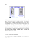
1
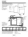
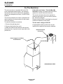
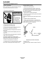
SLE400R
Introduction
To the owner or user: This service manual is
intended to provide you, and the maintenance or
service technician, with the information needed to
install, start up, clean, maintain and repair this
product.
The SLE400R is an ice machine that produces
cubed ice on 6 vertical cube freezing surfaces.
When harvested, the cubes fall individually into the
ice storage bin. The SLE400R automatically
maintains the level of ice by turning on when the
ice level falls, and switches off when the bin is full.
The refrigeration system uses R-404A as the
refrigerant.
Table of Contents
Specifications . . . . . . . . . . . . . . . . . . . . . . . . . . . . . . . . . . . . . . . . . . .
2
For The Installer: Environmental Limitations . . . . . . . . . . . . . . . . . . . . . . . . . . .
3
Installation
4
. . . . . . . . . . . . . . . . . . . . . . . . . . . . . . . . . . . . . . . . . . . .
Installation: Ice Storage Bin
. . . . . . . . . . . . . . . . . . . . . . . . . . . . . . . . . . .
Installation: SLD150 Hotel Dispenser
5
. . . . . . . . . . . . . . . . . . . . . . . . . . . . . .
6
Installation: Scotsman IS or RS Dispenser . . . . . . . . . . . . . . . . . . . . . . . . . . . .
7
installation
. . . . . . . . . . . . . . . . . . . . . . . . . . . . . . . . . . . . . . . . . . . .
8
Installation: Remote Condenser System . . . . . . . . . . . . . . . . . . . . . . . . . . . . .
9
Installation
10
. . . . . . . . . . . . . . . . . . . . . . . . . . . . . . . . . . . . . . . . . . . .
After Utility Connections
. . . . . . . . . . . . . . . . . . . . . . . . . . . . . . . . . . . . .
11
Component Location . . . . . . . . . . . . . . . . . . . . . . . . . . . . . . . . . . . . . . .
12
Initial Start Up . . . . . . . . . . . . . . . . . . . . . . . . . . . . . . . . . . . . . . . . . . .
13
Initial Start Up . . . . . . . . . . . . . . . . . . . . . . . . . . . . . . . . . . . . . . . . . . .
14
Maintenance, Cleaning and Sanitizing . . . . . . . . . . . . . . . . . . . . . . . . . . . . . .
15
Cleaning: Ice Machine Water System
. . . . . . . . . . . . . . . . . . . . . . . . . . . . . .
16
How It Works: . . . . . . . . . . . . . . . . . . . . . . . . . . . . . . . . . . . . . . . . . . .
17
Technical Characteristics . . . . . . . . . . . . . . . . . . . . . . . . . . . . . . . . . . . . .
18
Service Diagnosis:
. . . . . . . . . . . . . . . . . . . . . . . . . . . . . . . . . . . . . . . .
19
Removal and Replacement . . . . . . . . . . . . . . . . . . . . . . . . . . . . . . . . . . . .
22
Removal and Replacement . . . . . . . . . . . . . . . . . . . . . . . . . . . . . . . . . . . .
23
Removal and Replacement: Refrigeration System . . . . . . . . . . . . . . . . . . . . . . . .
24
Parts lists and wiring diagrams are located in the
center of this manual, printed on yellow paper.
Keep this manual for future reference.
This manual was printed on recycled paper.
Note the warning symbol where it
appears in this manual. It is an alert for
important safety information on a hazard
that might cause serious injury.
January 1995
Page 1
SLE400R
Specifications
Information regarding Model Number, Serial
Number, Ampacity and Maximum Fuse Size are
located on the nameplate of the ice machine. The
model number, serial number and refrigerant
charge are also listed on
the serial number plate
just behind the front
panel.
Nameplate
Serial Number
Plate
If recharging, always
use the charge listed on
the ice machine.
SLE400R Cabinet
Discharge Line
Fitting (3⁄8" OD)
Liquid Line
Fitting (1⁄4" OD)
Water
Inlet
Electrical
Inlet
Specifications:
The SLE400R will stack
onto a variety of ice
storage bins, see sales
literature for proper ice
storage bin.
SLE400R Back View
Drain
Model Number
SLE400RS-32A
Dimensions
W" x D" x H"
22 x 23 x 20
Condenser
Type
Remote Air
Basic
Electrical
Minimum
Circuit
Ampacity*
208-230/60/1
* Minimum Circuit Ampacity is used to determine
wire size and type per the National Electric Code.
Note: Do not connect this refrigeration system to a
used condenser circuit. Only the condenser and
line set specified for this machine may be used.
16.5
Maximum
Fuse Size (or
HACR circuit
breakers)
20
Condenser:
• RCE400-32A
Line Set:
• RTESL25 or RTESL40
January 1995
Page 2
Refrigerant
Charge.
R-404A
136 ounces
SLE400R
For The Installer: Environmental Limitations
The ice machine must be installed indoors in a
controlled environment.
Minimum
Maximum
0
Air Temp
55 F.
1000F.
Water Temp
400F.
900F.
Water Pressure 20 PSI
60 PSI
Voltage
253
198
Operating the ice machine outside of the above
limitations, or outdoors, is potentially damaging to
the machine, and it is misuse of the machine. This
may void the warranty.
Scotsman Ice Systems are designed and
manufactured with the highest regard for safety
and performance. They meet or exceed the
standards of UL, NSF, and CSA.
Scotsman assumes no liability or responsibility of
any kind for products manufactured by Scotsman
that have been altered in any way, including the
use of any part and/or other components not
specifically approved by Scotsman.
Scotsman reserves the right to make design
changes and/or improvements at any time.
Specifications and design are subject to change
without notice.
SLE400R
Top View
Dashed Lines Show
Outline of Ice Drop
Area.
Bin Control Mounts to
Right of Ice Drop Area.
12"
23"
7"
3"
6 1⁄2"
January 1995
Page 3
SLE400R
Installation
Water
Location
The water supply for this ice machine has been in
contact with many materials since it fell from the
sky as rain. All rain is slightly acidic, and tends to
dissolve the materials it comes in contact with.
During water’s journey to the ice machine, it has
flowed over and through the ground, been picked
up by a municipal or private pump, forced through
a series of pipes of differing construction and may
have been treated by the municipality providing
the water.
This ice machine may be installed in the open or
under a counter. Clearance may be required at the
sides, and is required at the back. Air cooled
models take air in from the right and blow it out the
back. Space is required for utility connections at
the back.
The water supplied to this ice machine will then
contain a variety of substances that will likely show
up as solids during the ice making process. These
solids are similar to those found when water is
boiled out of a saucepan. Only the water boils
away, and the minerals that were in the water
solidify in the pan. During ice making only the
water is frozen into ice, the minerals stay behind in
the reservoir. This machine drains out some water
in the reservoir every cycle to minimize the amount
of minerals in the water system, but after time the
minerals will appear and have to be dissolved by
ice machine cleaner, then flushed away during the
cleaning process.
The remote condenser may be located outdoors,
use the following formula for planning the
placement of the condenser relative to the ice
machine:
An ice machine is a food manufacturing plant; it
takes a raw material, in this case water, and
transforms it into a food product, ice. The purity of
the water is very important in obtaining pure ice
and in maximizing product life.
The water to the ice machine should be filtered.
Water filters vary greatly in ability and function.
Install one that filters out suspended solids to a
dimension of 5 microns or less. The finer the filter
the better, but finer filters may plug-up sooner than
course ones. It may be necessary to add a course
filter ahead of the fine filter to prolong filter life.
Polyphosphate feeders are usually effective in
many water conditions.
Have the water tested. Acidic water or alkaline
water will both cause corrosion. Dissolved solids
cannot be filtered out. Softened water is not
recommended. Never use de-ionized water.
Reverse-osmosis water must be treated with
buffering agents before use in the ice machine.
Check with a water treatment specialist regarding
testing, treatment and filters.
The ice machine is NOT designed for outdoor
use. It must be installed indoors, in a
controlled environment. The air and water
temperatures must not exceed rated limits.
• Maximum rise from ice machine to condenser
is 35’
• Maximum drop from ice machine to
condenser is 15’
Formula:
• Drop = n x 6.6
• Rise = n x 1.7 (n = distance in feet)
• Maximum distance is 100 equivalent feet.
For example:
• The condenser is to be located 5’ below the
ice machine and 20’ away.
• 5’ x 6.6 = 33 equivalent feet. 33 + 20 = 53
equivalent feet. This location would be
acceptable.
Pre-installation:
1. Inspect the place where the ice machine is to be
installed. Check for:
• space for the cabinet,
• water supply,
• drain availability
• and electrical power supply.
No extension cords are allowed. The building drain
inlet must be lower than the drain outlet of the ice
bin. The water supply must have a hand shut off
valve accessible when the unit is installed.
Remote Condenser:
A new condenser coil designed for the machine’s
capacity must be used. Because of the possibility
of mineral oil contamination, coils and line sets that
had been connected to R-12, R-404A or R-22
units may not be connected to this system. Doing
so voids the refrigeration system warranty.
January 1995
Page 4
SLE400R
Installation: Ice Storage Bin
Assembly:
Stacking:
1. Attach the legs, or optional casters, onto the ice
storage bin. Units that are stacked should only use
legs, not casters.
This machine will stack onto any SLC300, 400 or
SLE400R. Note: Do not use casters when
stacking. Note: One condenser per remote unit.
2. Be sure that the top edge of the bin has a good
gasket on it.
1. Remove and discard the left top panel from the
lower unit.
3. Place the ice machine onto the storage bin.
2. Remove knock out plug from top right panel.
4. Line up the ice machine, check that there is a
good seal between the ice machine and the
storage bin.
3. Place gasket material around the top of the
bottom unit’s cabinet & evaporator compartment.
5. If on a Scotsman bin, attach the ice machine to
the bin using the straps and bolts shipped with the
ice machine. Drill two 1/8" holes in the back of the
bin and secure with sheet metal screws provided.
If on another brand bin, follow the directions
included with that bin.
Bin Thermostat Installation:
4. Carefully lift the uncrated top unit onto the
bottom unit. Use of a mechanical lift is
recommended for this step.
5. Align the two ice maker cabinets.
6. Secure the top unit to the bottom one with the
hardware and straps shipped with the upper
machine.
1. Remove thermostat bracket from package.
7. Locate and uncoil all of the bin thermostat
capillary tube.
2. Attach the bin thermostat bracket to the bottom
of the ice machine using the thumb screws
provided. There are pre-drilled and tapped holes
located just to the right of the cube drop area.
8. Route the bin thermostat capillary tube from the
upper unit, through the hole in the base, through
the lower unit and into the bin thermostat bracket.
Discard upper unit bracket.
Bin Thermostat
Installation
Stacking
Routing Hole
Bin Thermostat
Bracket
Capillary Tube
Fasten Cabinets
Together At Back
With Straps &
Screws.
Bin Thermostat
Bracket
Thermostat
Capillary Tube
3. Locate and uncoil a portion of the
bin thermostat capillary tube. Route
the end of the capillary tube into the
plastic tube in the base of the ice
machine (next to the compressor) and
through the bin thermostat bracket.
Note: SLB150: Use thermostat
bracket packed with that bin.
January 1995
Page 5
SLE400R
Installation: SLD150 Hotel Dispenser
Assembly
The ice machine must be placed onto the top of
the dispenser, and the bin thermostat capillary
tube routed into the bracket in the dispenser.
1. Check that the dispenser has a gasket all
around the perimeter of the top, 22" wide by 23"
deep.
2. Locate the inlet hole of the thermostat bracket,
and make sure that it is open.
3. Place a corner post from the ice machine carton
at the front of left and right sides of the hotel
dispenser top.
4. Use a mechanical lift and place the ice machine
onto the dispenser. The cardboard corner posts
should keep the front edge of the ice machine up.
5. Remove the front panel of the ice machine.
6. Locate the bin thermostat capillary tube and
uncoil about 18" of tubing.
7. Locate plastic tube in base of ice
machine, next to compressor and
push the end of the capillary tube thru
the tube, watch the capillary as it
comes out of the base, line it up with
the inlet hole of the thermostat
bracket and push it into the hole.
Move the cabinet of the ice machine
until the capillary tube is going
straight down into the inlet hole.
Bin Thermostat Capillary
Tube Installation
Route Capillary Tube
Through Plastic
Tube In Base
8. Carefully remove the corner posts.
9. Push the capillary tube into the
thermostat bracket tube until about
14" of capillary tube is in the tube.
9 Remove the hardware package
from the machine, remove brackets.
10. At the back of the dispenser,
fasten brackets to the ice machine.
11. Using brackets for templates, drill
1/8" holes into the back of the
dispenser.
Bin Thermostat
Bracket Mounted In
Dispenser
12. Secure brackets to the dispenser
with sheet metal screws from the
hardware package.
13. Follow other installation
instructions from the SLD150.
January 1995
Page 6
Temporarily
Support Machine
With Corner Posts
To Observe Cap
Tube Installation
SLE400R
Installation: Scotsman IS or RS Dispenser
Assembly:
The assembly of the ice machine onto the
dispenser requires two additional parts: an adapter
kit and a thermostat stand off kit.
1. Mark two spots on the inside left liner of the
dispenser: 2" down from the top, 4" from the back,
and 4" apart.
7. From the adapter kit, place the stainless steel
adapter onto the top of the dispenser. Follow all
directions included with the kit.
8. After the ice machine has been placed on the
dispenser, remove the front panel and uncoil all of
the bin thermostat capillary tube.
2. At the two marked spots, drill two 1/4" holes thru
the plastic liner only.
9. Route the capillary tube thru the front hole in the
base of the ice machine, to the left side if the
dispenser towards the stand offs.
3. From the stand off kit, locate the stand offs and
plastic anchors. Thread the stand offs partially into
the plastic anchors.
10. Route the end of the capillary tube thru the
stand offs, bend the tube around the stand offs so
that it does not fall off.
4. Push the anchors/stand offs into the holes.
11. Check that the routing of the capillary tube is
away from the ice chute and up high near the base
of the ice machine.
5. Screw the stand offs all the way into the
anchors. Be sure that the holes in the stand offs
are horizontal.
6. Place a bead of silastic (from the kit) around the
stand offs.
Installation of Bin Thermostat
Capillary Tube
Route Capillary
Tube Through Front
Plastic Tube
K1 Kit Adapter
RS or IS
Dispenser
Stand Offs From Kit K6
Drill 2 Holes For
Stand-Offs:
2" From Top Of
Dispenser &
4" From Back &
4" Apart
Route Capillary
Tube Through
Stand Offs
January 1995
Page 7
SLE400R
installation
For The Plumber
Supply:
Screw the 3/8" male flare (fitting shipped in
package inside cabinet) into the 1/4" FPT fitting at
the back of the cabinet (thread tape
recommended). Connect cold potable water to the
water inlet. A hand shut off valve for inlet water
should be installed near the machine. A water filter
is recommended. Flush the water line prior to
connecting to the ice machine.
Drains:
Connect a drain tube to the reservoir drain fitting at
the back of the cabinet. The drain tube from the
fitting must be run separately from any other drain
tube. The reservoir drain is a 3/4" F.P.T. brass
fitting.
The bin drain must be vented if there is a long
horizontal run (5’ or more). The reservoir drain
must be vented and not connected to the bin
drain. All drains are gravity, and must have a
minimum fall of 1/4" per foot of horizontal run.
Maintain the air gap required by local code
between the end of the drain tubes and the
building drain receptacle.
Note: Drain tubing should be insulated to prevent
condensation from forming on the tubing.
CONFORM TO ALL LOCAL CODES
Drain tube material must be rigid and meet local
code.
Traps in the bin drain line without vents ahead of
them will cause poor draining.
3/8 Male Flare
Water Inlet
Water Shut
Off Valve
Reservoir Drain
3/4" FPT, Must Be Vented.
Ice Storage Bin
(Typical)
Bin Drain. May Be Routed From
The Bottom On Some Model
Bins. Fitting May Be Plastic.
DO NOT OVERHEAT.
Water Supply and Drain Connections
January 1995
Page 8
SLE400R
Installation: Remote Condenser System
Remote Condenser
The remote condenser may be located within 100
equivalent feet of the ice machine (per the
formula). Follow all local building codes for the
condenser’s location. If placed on a roof, a roofing
specialist should install it.
Pre-Charged
Line Set
Remote
Condenser
Precharged Lines
There are two precharged lines required for each
ice machine to condenser connection: a 1/4" liquid
line and a 3/8" discharge line (the discharge line is
insulated). Each contains a minor holding charge
that matches the type of refrigerant in the ice
machine and in the condenser. The ice machine
contains the entire system charge in the receiver.
From the formula, plan the routing of the tubing.
Do not leave any excess tubing on the roof: the
condenser must be located as close as possible to
the place where the tubing goes through the roof.
Route the tubing to the condenser and to the ice
machine. Be certain that there is no metal to metal
or tight tube to tube contact between the liquid and
discharge lines.
Coil excess tubing inside the building in a
horizontal spiral.
If there is considerable excess tubing, it should be
cut out before the tubing is connected to the ice
machine. Be certain to evacuate the tubing before
connecting to the ice machine or to the remote
condenser.
Connections:
Remove plastic caps from condenser, tubing
connections and from the ice machine’s refrigerant
tubing connections. Lubricate all threads and
o-rings with refrigeration oil.
Tighten all fittings until a significant resistance is
felt. Then using two wrenches, (one holding the
tubing so that it does not rotate) tighten the
connections 1/4 turn more.
Check fittings for leaks and have the roof hole
sealed.
Wiring:
The remote condenser fan motor takes its power
from the ice machine. Wire per electrical codes
and the wiring diagram.
January 1995
Page 9
Installation of Remote Condenser
SLE400R
Installation
For The Electrician
This unit must be on a separate 230 volt AC 60
cycle single phase power supply. The maximum
fuse size for this circuit is listed on the nameplate,
and per the nameplate use fuses, or HACR circuit
breakers.
The remote condenser fan motor is powered from
the ice machine, thru the junction box at the back
of the ice machine.
Follow All Local Codes - This Unit Must Be
Grounded. Usually a licensed electrician will be
required to connect the electrical service.
The remote condenser fan motor requires an
electrical connection in the ice machine junction
box. See wiring diagram.
Remote wiring must be in liquid tight or rain proof
conduit as required by local codes.
To make the electrical connections:
The fan motor voltage is 208-230.
1. Remove the right top panel.
An appropriate outdoor junction box may be
required to be added to the remote condenser.
2. Remove the junction box cover.
3. Make the electrical connections to the wires in
the junction box. A ground screw is provided in the
junction box.
Remote Electrical
Connection
Power Supply for Ice Maker
and Condenser
Junction Box
SLE400R BACK VIEW
January 1995
Page 10
SLE400R
After Utility Connections
1. Level the cabinet, use the leg levelers on the
end of the legs to adjust the cabinet height. (Legs
should have been installed when the bin was
unpacked).
2. Wash out the bin. If desired, the interior of the
bin could be sanitized.
Final Check List
1. Is the ice maker cabinet in a room where
ambient temperatures are within the minimum and
maximum temperatures specified?
2. Has the water supply been connected?
3. Is the water pressure adequate?
4. Have the water connections been checked for
water leaks?
5. Have the drain connections been made?
6. Have the drain connections been checked for
leaks?
7. Is the cabinet level?
8. Is the ice machine connected to a 230 volt
electrical power supply and is the ice machine the
only load on that circuit?
9. Has all of the shipping material been removed
from the inside of the cabinet?
10. Has the bin thermostat been installed?
11. Has the remote condenser been installed in an
acceptable location?
12. Have the precharged tubes been connected?
13. Has the ice maker to remote condenser
electrical connection been made?
14. Has the bin and cabinet been wiped clean and
sanitized?
15. Has the Customer Evaluation & Warranty
Registration form been properly filled out? Check
for correct model and serial numbers from the
nameplate, then mail the completed form to
Scotsman.
16. Has the owner/user been given the name and
telephone number of the authorized Scotsman
Service Agency serving that location?
January 1995
Page 11
SLE400R
Component Location
Many components are serviceable from the front
without removing the side panels.
Control Box Detail
Ice Size
Thermostat
Behind the front panel:
• Water pump
• Inlet water valve
• Reservoir
• Evaporators
• Water distributor pan
• Ice size control adjustment
• ICE/OFF/WASH switch
• Control box
Contactor
High
Pressure
Cut Out
Compressor
Relay
Harvest
Relay
Bin
Thermostat
Ice/Off/Wash
Switch
Ice Thickness Control
Control Box
Water Distributor
Pan
Bin Thermostat
ICE/OFF/WASH Switch
Bin Thermostat
Bracket
Water Pump
Water Inlet Valve
& Strainer
Drain Elbow
Component Location
January 1995
Page 12
SLE400R
Initial Start Up
After the final check list has been gone through,
the ice machine may be started up.
Ice Size Adjustment
1. Open the water shut off valve; the inlet water
valve will open, and water will flow into the
reservoir..
Ice Thickness Probe
Adjustment Plate:
Move UP for Larger
3. Remove the front panel.
Cubes,
3. Locate the ICE/OFF/WASH switch, DOWN for Smaller
Cubes
switch it to WASH.
2. Switch on the electrical power.
Set
Screws
4. The water pump will begin to pump
water over the evaporators.
5. Allow the reservoir to refill. Normal water level is
1/8" below the high point of the lower curve of the
siphon u-tube.
Cube Size Diagram
6. Switch the ICE/OFF/WASH switch to OFF.
7. Check the action of the siphon. The water level
in the reservoir should drop to the bottom curve of
the U-bend (normal water level) in about 2
minutes. If not, check for proper drain tube
connections.
Cubes Too
Thick
8. Remove right side panel.
9. Remove cap from “king” or service valve on the
receiver, and open the valve.
10. Switch the ICE/OFF/WASH switch to ON.
11. The remote fan motor will begin to turn, and
warm air will be discharged from the top of the
remote condenser.
12. The water temperature in the reservoir will
soon be 320F., and ice should begin to form on the
evaporators.
13. Allow the ice machine to operate for about 20
minutes. The ice should be fully formed and
should be harvested within a few minutes.
Correct Size &
Shape
14. After harvest, check the ice cube size.
Compare a fresh cube to the diagram on the
back of the front panel. If needed, adjust the
cube size by loosening the set screws and moving
the ice thickness probe adjustment plate.
Move the adjustment plate down for smaller
cubes and up down for larger.
For proper operation, the ice thickness should be
set to the 1 11⁄16" diameter.
The machine is designed to harvest cubes of
only the correct thickness.
January 1995
Page 13
Cubes Too
Thin
1 11⁄16"
SLE400R
Initial Start Up
Note: If the first batch of cubes are not all uniform
discs, some ice machine cleaner should be added
to the reservoir.
1. After ice has been harvested, but before new
cubes begin to form, switch the ICE/OFF/WASH
switch to WASH.
2. Add 4 oz. of ice machine cleaner to the
reservoir. Allow unit to operate that way for 10
minutes.
3. Switch ICE/OFF/WASH switch to OFF
4. Shut the water supply off.
5. Remove the splash guard, and drain the
reservoir by removing the drain elbow.
7. Replace all parts, turn on the water and
move ICE/OFF/WASH switch to ICE. The next
batch of ice should be uniform.
13. Check harvest. The machine will have to
harvest all of the cubes before it goes back into the
freeze cycle.
14. Check operation of the bin control circuit by
holding ice on the bin control tube in the bin.
If the ice maker does not stop within 1 minute,
while keeping ice on the thermostat, rotate the bin
thermostat shaft counter clockwise until the ice
maker does stop. Remove the ice from the
capillary tube; the ice maker should restart within 2
minutes. If it does not, rotate the adjusting shaft
clockwise until the machine starts.
15. Replace all the panels. The ice machine is now
ready for automatic operation.
Siphon Tube Schematic
U-Tube Adjusted
Here = No Purge
Electrical Sequence:
Freeze Cycle:
During the first part of the freeze cycle, the ice
machine compressor, fan motor and water pump
are operating.
Assume the bin thermostat is open (low ice), relay
K1 will NOT have power thru its coil and K1
contacts 6-2 will be closed, connecting power to
the ice size thermostat and the liquid line valve coil.
The ice size thermostat contact 2-3 are closed,
connecting power to the fan motor and the pump
motor.
The Harvest Termination Thermostat is closed to
NC, but there is no power thru it.
The ice size thermostat heater is on, and the
compressor contactor coil is energized.
Harvest:
In the harvest cycle, the compressor is operating,
and the hot gas valve is energized. The fan and
and pump are off. The bin thermostat is still open.
The when the ice near the ice size thermostat
sensing tube grows large enough to force water
over the sensing tube, that tube looses heat, and
at 38oF. contacts 2-3 open and 2-1 close.
This removes power from the water pump and
remote fan and connects power to the relay coil.
When the relay coil has power, it connects power
to the hot gas valve coil.
The harvest termination switch is closed, and
power flows thru it to the relay coil. This keeps the
relay energized, even when the ice size thermostat
switches contact position as a result of ice falling
away from the sensing tube.
The unit stays in the harvest cycle until the
thermodisc on the suction line warms up to 55oF.,
U-Tube Here =
At that time the defrost themodisc switches to NO
Maximum Purge
and the harvest cycle is terminated. If the bin
Water Level
thermostat is still open, relay K1 will still not have
At Harvest
power and the unit will go back into the freeze
Water Level With cycle. If relay K1 has power, it shuts off the ice
Pump ON
machine by cutting power to the liquid line valve,
after the unit pumps down, the low pressure
Water Inlet
control shuts off the compressor.
Siphon Breaker Hole
1/8 - 1/4
Drain Outlet
Elbow
Bottom of
Reservoir
Whenever there is ice on the bin thermostat, it
closes a circuit to the coil of relay K1 and stops the
ice making process at the end of a harvest cycle.
The crankcase heater is on at all times.
January 1995
Page 14
SLE400R
Maintenance, Cleaning and Sanitizing
Cleaning Schedule:
Ice Storage Bin
• Scrub the outside of the cabinet once a week
with soap and water.
• Sanitize the bin interior once a month.
• Clean the water system and air cooled
condenser a minimum of twice per year. If in
an area of high mineral concentration in the
water supply, clean water system 4 times a
year.
Inlet Water Valve Screens
If a restriction of incoming water is suspected,
there may be a strainer in the water line; the
strainer screen should be inspected for restricting
minerals. Water filters should be changed.
Air Cooled Condenser:
The interior liner of the bin is in contact with a food
product: ice. The storage bin must be cleaned
regularly to maintain a sanitary environment.
Once a week cleaning with soap and water, a hot
water rinse and an air dry is a basic procedure.
Every 30 days, the liner should be sanitized with a
commercial ice machine sanitizer, according to the
directions of the sanitizer, or with a solution of
household bleach and water:
1. Mix the bleach and water using the ratio of two
ounces of bleach to two gallons of water.
2. Wipe all interior surfaces of the ice storage bin
with the bleach and water.
3. Allow to air dry.
Shut the unit off.
To Remove Scale:
The fins of the condenser will become fouled with
dirt, and must be cleaned. A vacuum cleaner with
a soft brush attachment will extract most loose
dust stuck to the surface of the condenser fins..
1. Mix a cleaning solution of 4 ounces of Scotsman
Ice Machine Cleaner to 4 pints of warm
(950F.-1100F.) water.
2. Using rubber gloves, dip a nylon scouring pad
into the cleaning solution and scrub the scale off
the liner.
3. After the scale has been removed, rinse all
surfaces inside the bin with clean, potable water.
Stainless Steel Bin Liner
The stainless steel liner of the bin will require
periodic cleaning. Chemicals in the water supply,
such as chlorine, cause brown stains to appear on
the surface of the stainless steel parts.
1. General Cleaning - staining is usually removed
by washing the parts with ordinary cleaning
powder such as Bon-Ami or Copper-Glo and
water. After cleaning, rinse with clear water.
2. Water treatment. The chlorine enters the
machine from the municipal water supply. It can be
removed from the water supply by using a
charcoal or activated carbon water filter to treat the
water to the ice machine. If staining is severe,
filters of this type are recommended.
Exterior Cabinet Cleaning:
The exterior cabinet may be cleaned by scrubbing
with soap and water. Do not use cleaners
containing petroleum products.
A nylon type brush may be used to scrub stubborn
deposits.
January 1995
Page 15
SLE400R
Cleaning: Ice Machine Water System
Dissolve and Remove Minerals:
15. Shut the water supply off by pushing the water
valve button in.
1. Remove front panel.
16. Drain the water from the sump by removing the
drain elbow.
2. Move the ICE/OFF/WASH switch to OFF.
3. Remove the splash guard.
4. Shut the water supply off by pushing the water
valve button in.
5. Drain the water from the sump by removing the
drain elbow.
6. Disconnect hose from the water distributor pan,
and remove the water distributor pan.
7. Mix a solution of 5 oz. ice machine cleaner and
1 gallon of warm (95oF. - 115oF.) water.
Scotsman Ice Machine
Cleaner contains
acids. These
compounds may
cause burns.
If swallowed, DO NOT
induce vomiting. Give
large amounts of water
or milk. Call Physician
immediately. In case of
external contact, flush
with water.
KEEP OUT OF THE
Sanitize:
17. Remove the water distributor pan.
18. Mix a sanitizer solution of 1 ounce of
household bleach to 2 gallons of warm (95oF. 115oF.) water
19. Wash the splash guard and the water
distributor pan with the solution of sanitizer. Allow
to air dry.
20. With the sanitizer solution, wash the
refrigeration tubing, liner, evaporators, support
brackets and water pump assembly; use the brush
and/or a clean cloth.
21. Replace the water distributor pan and splash
guard. Be certain that the hose to the water
distributor pan is tightly connected to the pan, and
that the flow washer in the hose is not in sideways.
22. Replace the drain elbow.
23. Add ice machine sanitizer solution to the sump
area until it is full.
8. Wash the splash guard, drain elbow and water
distributor pan with the ice machine cleaner/water
solution.
9. With the solution of ice machine cleaner and
water, wash the refrigeration tubing, liner,
evaporators, support brackets and the water pump
assembly. Use the brush and/or a clean cloth.
10. Replace the drain elbow.
11. Open the water supply by pushing the water
valve button in (to its original position) and allow
the sump to refill.
12. Add 5 oz. ice machine cleaner to the sump
area.
24. Move the ICE/OFF/WASH switch to WASH
add more sanitizer solution to the sump area until
it is full again.
25. After 5 minutes, move the ICE/OFF/WASH
switch to OFF.
26. Remove the splash guard.
27. Drain the water from the sump by removing the
drain elbow.
28. Replace the drain elbow and splash guard
29. Open the water supply by pushing the water
valve button in (to the original position) and allow
the sump to refill.
30. Move the ICE/OFF/WASH switch to ICE.
31. Replace the front panel.
13. Replace the water distributor pan and splash
guard. Be certain the hose to water distributor pan
is connected to pan.
32. Discard first batch of ice and all other batches
until all traces of cleaner and sanitizer disappear.
14. Move the ICE/OFF/WASH switch to wash and
allow the solution to circulate for 15 minutes, then
move the ICE/OFF/WASH switch to OFF.
17. Remove the splash guard.
January 1995
Page 16
SLE400R
How It Works:
Refrigeration: Freeze Cycle:
Water:
From the compressor, hot discharge gas is
pumped to the remote air cooled condenser.
Water flows into the ice machine from its inlet
connection at the back of the cabinet, through the
inlet water valve and into the reservoir. The water
in the reservoir is pumped up and through the
water distributor tube at the top of the evaporators.
From there, the water flows over both sides of the
evaporators and back into the reservoir.
At the condenser, if the discharge pressure is over
225 PSIG, the discharge gas will flow thru the
condenser coil. Heat from the refrigerant flows into
the air, and the refrigerant condenses into a liquid.
If the discharge pressure is below 225 PSIG, the
refrigerant will not flow thru the coil, but will be
forced into the liquid line.
From the condenser the liquid refrigerant flows
through the liquid line to the liquid line check valve.
When the machine is on, the check valve is open
to flow from the condenser to the receiver.
From the receiver, refrigerant then flows to the
metering device - a thermostatic expansion valve.
At the expansion valve, the liquid refrigerant
passes from a high pressure zone to one of
relatively low pressure, and in the low pressure
zone it evaporates. The low pressure zone where
the refrigerant evaporates is the evaporator. When
the refrigerant evaporates, it absorbs heat from the
metal parts of the evaporator and the water flowing
over it.
From the evaporator, the refrigerant flows back to
the compressor through the suction line.
Note: During the time that the machine is off, the
the pump down system (liquid line valve) keeps
the refrigerant out of the low side of the system,
and the liquid line check valve keeps liquid
refrigerant from flowing back into the liquid line and
remote condenser.
Melted ice and water spills into the bin flow
through a drain in the base of the bin to the
exterior drain connection at the back of the cabinet.
Refrigeration: Harvest Cycle:
The ice maker continues to freeze the water into
ice until the ice next to the ice size thermostat
probe has become thick enough to force water
over the probe. After the cold water has reduced
the temperature of the probe to 380F., the ice size
thermostat will switch the machine into the harvest
cycle.
During the harvest cycle, the refrigerant flows from
the condenser, through the discharge line to a
branch in the line containing the Hot Gas Valve.
This valve is Open during the harvest cycle,
allowing the hot discharge gas to bypass the
condenser and enter the evaporator at its inlet.
The hot discharge gases warm up the evaporator
enough to allow the surface of the ice frozen to the
evaporator to melt. The remaining ice will then fall
off into the bin.
During the Harvest Cycle, the water level rises,
filling the reservoir over the siphon tube and
siphoning some of the reservoir water out to the
drain. The harvest cycle continues until the suction
line warms up enough to cause the harvest
termination thermostat to switch the machine back
into the freeze cycle.
January 1995
Page 17
SLE400R
Technical Characteristics
Typical Cycle Time
• 17 minutes @ 70oF. air and 50oF. water
• 24 minutes @ 90oF. air and 70oF. water
Typical Harvest Ice Weight
• 4 pounds .
Typical Low Side Pressure
• 22 - 23 PSIG just before harvest (beginning of freeze may be 45 - 50 PSIG)
Typical Freeze Cycle Discharge Pressure
• 240 - 260 PSIG
• Minimum (low temps) = 225 PSIG
Refrigerant Charge:
• 136 ounces R-404A
Harvest Time
• Normally 11⁄2 to 2 minutes. Depends upon time required to warm suction line to 55oF.
Typical Suction Pressure, In Harvest:
• 110- 120+ PSIG
Typical Discharge Pressure, In Harvest:
• 130 - 150 PSIG
Typical Compressor Amp Draw:
• 4 - 5 during freeze cycle; 5 - 6 during the harvest cycle
Compressor:
• Copeland: RS64C1E-CAV-214
Thermostatic Expansion Valve
• Superheat is 3o - 6oF.
Pump down pressure control
• Cut Out at about 10 PSIG
• Cut In at about 25 PSIG
Bin Thermostat
• Cut In to shut off machine at 35oF., cut out at 39oF.. Adjustable warmer.
Ice Size Thermostat:
• Switches to harvest cycle with temperature fall to 38oF.. Resets at 43oF.
Ice Size Heater
• Adds heat to ice size thermostat to prevent premature harvest.
Harvest Termination Thermostat
• Switches
from contacts C-NC to contacts C-NO to switch to freeze cycle with temperature rise to
55oF. Resets at 40oF.
January 1995
Page 18
SLE400R
Service Diagnosis:
SYMPTOM
No ice is made, nothing operates
No ice, compressor off
No ice is made, compressor is
operating
POSSIBLE CAUSE
Unit off, due to no power
Unit off, due to ICE/OFF/WASH
switch in OFF position
Unit off, due to bin thermostat
closed
Unit off, due to high pressure cut
out open
No cooling due to compressor not
operating
Unit off, due to low pressure
(pump down) control open.
No water due to water turned off.
No water due to water filter
plugged.
No water due to strainer screen
plugged
No water due to inlet water valve
will not open
Water in reservoir, but no water
over evaporators
No cooling at evaporator due to
hot gas valve leaking thru
No cooling at evaporator due to
fan not turning
Fan and pump do not have
power; hot gas valve opens and
closes.
No cooling at evaporator due to
dirty condenser
No cooling due to compressor not
pumping
January 1995
Page 19
PROBABLE FIX
Restore power
Switch ICE/OFF/WASH switch to
ICE
Check temperature at bin
thermostat bracket, if warmer than
40o F., thermostat should be
open. Adjust/replace thermostat.
Check fan motor.
Check compressor for voltage,
continuity, and operation. Check
starting components. Replace if
found to be faulty.
If no voltage, check contactor,
replace if coil or contacts open.
Check temperature of
compressor, if hot may be lack of
refrigerant, defective TXV or
compressor
Check liquid line valve coil for
power and/or continuity
Reconnect water supply
Replace water filter
Clean out inlet screen
Replace valve
Water pump does not work,
replace pump
Replace hot gas valve
Check & replace fan motor.
Coil or relay open, replace relay.
Clean condenser
Check system pressures, replace
compressor if not pumping
SLE400R
Service Diagnosis:
SYMPTOM
No ice compressor is operating
POSSIBLE CAUSE
No cooling due to low refrigerant
charge
Ice is made, but not harvested.
Ice size thermostat contacts do
not switch position
Ice will not slide down ice rack
due to minerals on rack.
Ice will not slide down ice rack
due to ice rack out of position
Ice will not slide down ice rack
due to bent ice rack
Lack of heat during harvest cycle
due to unit in air temp. less than
550F.
Lack of heat during harvest due to
water flowing thru water cooled
condenser
Lack of heat during harvest due to
lack of refrigerant
Lack of heat during harvest due to
hot gas valve not opening fully.
Ice does not slide down face of
evaporator due to minerals on
evaporator surface
Harvest cycle too short due to
harvest termination thermostat
opens at too low a temperature.
January 1995
Page 20
PROBABLE FIX
Locate leak, recover remaining
refrigerant, replace dryer,
evacuate and weigh in nameplate
charge.
Ice not made near thermostat
probe due to water distributor
holes restricted. Clean water
distributor pan.
Thermostat defective, replace it
Clean machine with ice machine
cleaner.
Reposition ice rack
Replace ice rack
Warm up air or move machine.
Replace water regulating valve
Check low side pressure during
harvest. If low either the charge is
low or the hot gas valve does not
open fully. If charge is the
problem, locate leak, recover
remaining refrigerant, repair leak,
replace drier, evacuate and weigh
in nameplate charge.
Check low side pressure during
harvest. If low either the charge is
low or the hot gas valve does not
open fully.
Clean water system with ice
machine cleaner
Replace harvest termination
thermostat
SLE400R
Service Diagnosis:
SYMPTOM
Ice is made, but will not harvest
POSSIBLE CAUSE
Will not harvest due to hot gas
valve not opening.
Slow/incomplete harvest due to
hot gas valve not fully open.
Makes ice, but very little
Cubes are wrong size/shape
High discharge pressure, due to
dirty condenser; faulty fan motor;
Inlet water temperatures and
room ambient very high
Long freeze cycle due to hot gas
valve leaking thru.
Compressor inefficient
Ice size thermostat not adjusted
properly
Freeze cycle too short due to
heater open
Water system is restricted with
minerals
Ice thickness probe tube covered
with minerals
Not enough water
Too much superheat
Ice fused together in bin
Ice in bin too long
Unit does not shut off
Too many minerals in water
Bin control will not close
K1 relay coil open
January 1995
Page 21
PROBABLE FIX
Check for voltage to coil in
harvest, if there is voltage replace
hot gas valve
Check low side pressure in
harvest, replace hot gas valve if
too low with correct ref. charge.
Check for causes of high
discharge pressure and correct.
Advise user, suggest additional
room cooling.
Check temperature of tubes to
and from hot gas valve; there
should be a temperature drop
across the valve in the freeze
cycle. Replace valve if temps are
nearly equal.
Check/replace compressor
Adjust ice size thermostat; use
gauge shipped with machine
Check/replace heater on ice size
thermostat probe tube.
Clean water system with
Scotsman Ice Machine Cleaner
Clean tube with ice machine
cleaner
Check water supply pressure
Check water supply for restrictions
Check superheat, replace TXV if
too high.
Check hot gas valve for leak-thru;
replace if leaks thru.
Advise user to pour water on ice
to ease removal
Suggest water treatment to user.
Check & replace bin control
Check & replace K1 relay
SLE400R
Removal and Replacement
Ice Size Thermostat:
Primary Resistor (Heater)
Before replacing the ice size thermostat, it should
be positively determined that it is at fault.
1. Disconnect electrical power.
1. Disconnect electrical power.
2. Disconnect the primary resistor’s yellow wire
from terminal #4 and the white wire from terminal
#1. Pull the two wires out of the control box and
thru the insulated wall.
3. Mark location of probe tube bracket.
Electrical shock
hazard.
Electrical shock can
cause personal injury.
Disconnect power
before beginning to
service components.
4. Remove two screws and the probe tube bracket
from the evaporator.
5. Remove the plastic sleeve and heater from the
tube.
6. Replace heater and plastic tubes.
7. Place probe tube bracket on evaporator in its
original position. Probe tube must be inserted into
plastic guide attached to evaporator.
2. Remove the front panel.
Evaporator
3. Remove the control box cover.
4. Locate the ice size thermostat.
5. Remove the two screws holding the control to
the control box, and lift the control out.
Heater
6. Pull the three wires off the posts of the ice size
thermostat.
7. Follow ice size thermostat capillary tube to ice
size probe.
Capillary
Tube
8. The end of the ice size thermostat is inserted in
a tube. Pull it out of the tube.
Probe Tube Bracket
9. Follow the capillary tube of the ice size
thermostat and pull it thru the insulated wall and
the grommet in the side of the control box.
10. Remove thermostat from control box.
Replacement of Ice Size Thermostat
11. Replace the ice size thermostat with the proper
part number, following the above steps from 9-1.
8. Replace wires.
9. Reconnect power, restart ice maker. Check ice
size.
January 1995
Page 22
SLE400R
Removal and Replacement
Water Pump
Inlet Water Valve
The pump provides the force to move the water
from the reservoir to the freezing surface. The
pump does not need oil, but if it becomes noisy,
overheats, or will not pump it should be replaced.
Be certain to confirm electrical faults with a
voltmeter or ohmmeter before replacing the pump.
The pump should be operating whenever the
machine is in the freeze cycle.
The valve may plug-up from minerals in the water,
and should then be cleaned rather than replaced.
There is also a strainer located above the float
valve that may be cleaned.
1. Unplug or disconnect the electrical power.
3. Remove the screws holding the valve bracket to
the liner.
1. Shut off the water supply.
2. Unscrew the fitting at the top of the valve, and
pull the water inlet tube out of the valve body.
4. Remove the valve from the ice machine.
5. Reverse the above steps to reassemble.
Electrical shock
hazard.
Electrical shock can
cause personal injury.
Disconnect power
before beginning to
service components.
2. Unplug the pump from its connection.
5. Loosen the two fasteners holding the cover to
the wall.
Pump Cover
6. Remove pump cover from the machine.
7. Pull discharge hose from pump discharge port.
8. Remove pump from ice machine.
Thumb
Screws
9. Reverse above steps to replace.
Float Valve
Siphon “U” Tube
January 1995
Page 23
Replacement of Water
Pump
SLE400R
Removal and Replacement: Refrigeration System
General Information
Work on the refrigeration system should only be
done when it is certain that the system needs
repair.
• This ice machine use R-404A (HP62)
refrigerant and the compressor uses Polyol
Ester oil.
• Do NOT use mineral oil in this refrigeration
system.
• R-404A is a “near azeotrope” and therefore
liquid charging is required.
• When the system is serviced, a special liquid
line dryer is required.
• Polyol ester oil absorbs water very easily, and
when the system is opened for service, it
must be re-sealed as soon as possible (15
minutes maximum).
• Special leak detection equipment is required
to locate small refrigerant leaks. Usually a
leak detector capable of detecting a
Halongenated refrigerant or HFC-134a will
work. Check with the leak detector
manufacturer if in doubt.
• As with any other refrigerant, do not mix
R-404A with pressurized air when leak testing.
• Evacuate the system to 200 microns before
charging.
• Weigh the nameplate charge into the receiver.
January 1995
Page 24