1
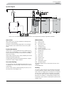
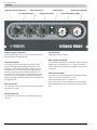
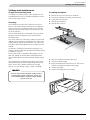
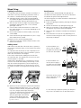
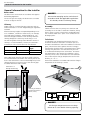
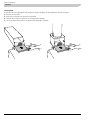
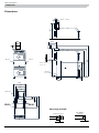
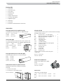
MOS GB 1248-1
VEDEX 3300
231312
LE
K
INSTALLATION AND MAINTENANCE INSTRUCTIONS
VEDEX 3300
Contents
For Home Owners
System diagram____________________________________ 3
Electrical installation
Area of use _______________________________________ 3
Connection_______________________________________ 13
Product description _________________________________ 3
Wiring diagram___________________________________ 14
Hot water heating__________________________________ 3
Abbreviations______________________________________ 3
Heating___________________________________________ 3
Settings, instructions and maintenance
Service
Sweeping description______________________________ 15
Fan15
Cover plate_______________________________________ 16
Charge and circulation pump ________________________ 5
Sweeping_________________________________________ 5
Sweeping description _______________________________ 5
General instructions_________________________________ 6
Primary air control__________________________________ 6
Boiler default settings_______________________________ 6
Other information
Pellet firing in VEDEX 3300
Installation and sealing_____________________________ 17
Turbulators_______________________________________ 17
Reconfiguring_____________________________________ 17
Wood firing
Sweeping description ______________________________ 17
Lighting instructions________________________________ 7
Accessories_______________________________________ 17
Adding wood______________________________________ 7
Readjustment______________________________________ 7
Technical specifications/Technical specifications
Component location, boiler section__________________ 18
For the Installer
Component location, front panel____________________ 18
List of components________________________________ 19
General information for the installer
Boiler room________________________________________ 8
Chimney__________________________________________ 8
Assembly__________________________________________ 8
Turbulators________________________________________ 8
Installing ceramics__________________________________ 9
Dimensions_______________________________________ 20
Measuring principle________________________________ 20
Enclosed kit______________________________________ 21
Accessories_______________________________________ 21
Technical data/Technical specifications________________ 22
Pre-installed ceramic kit_____________________________ 9
Ceramic grate______________________________________ 9
Flame trough______________________________________ 9
Pipe installation
Connection_______________________________________ 10
Flue gas thermometer______________________________ 10
Filling____________________________________________ 10
Draining_________________________________________ 10
Cooling coil______________________________________ 10
Environmentally friendly approved____________________ 10
Docking to the accumulator
Abbreviations_____________________________________ 11
Dockings ________________________________________ 11
VEDEX 3300
1
For Home Owners
General
Thank you for relying on NIBE to supply your boiler and congratulations on choosing VEDEX 3300, a high quality
wood boiler with a long service life, developed and manufactured in Sweden for Swedish conditions.
In order to get the ultimate benefit from VEDEX 3300 you should read through these Installation and
Maintenance Instructions. The numbers in brackets refer to the section “Component locations”.
The boiler is designed for houses with water borne heating and is environmentally approved for accumulator tank
firing.
To be filled in when the product has been installed
The serial number (103), must always be stated in all correspondence with NIBE.
______________
Installation date:
Installer:
Date:_______
Sign:______________________
This appliance is not intended for use by persons (including children) with reduced physical, sensory or mental capabilities or lack of experience and
knowledge about the appliance, unless they have been given supervision or instruction concerning the use of the appliance by a person responsible
for their safety. Children should be supervised to ensure that they do not play with the appliance. We reserve the right to make design modifications
without prior notice. ©NIBE 2012
2
VEDEX 3300
For Home Owners
General
System diagram
T
EXP
AV
SÄV
CP2
RC
SV1
SV2
LV
T
T
T
VVB
ACCU
ACCU
ACCU
ELK
AV
AVT
AV
CP1
AV
AVT
BV
AV
AV
AV
AVT
AVT
SV4
NOTE! This is an outline diagram. Actual installations must be planned according to applicable standards.
Area of use
Abbreviations
NIBE VEDEX 3300 is a boiler intended for heating houses
and other small buildings.
AV Shut-off valve
AVT Draining valve
BV Non-return valve
CP1 Charge pump
CP2 Circulation pump
ELK Immersion heater
EXP Level vessel/expansion vessel
LV
Venting valve
MV Motor valve
RC Control box
SV1 Shunt valve
SV2 Mixer valve
SV4 Thermal valve
SÄV Safety valve
TG Temperature sensor
VVB Hot water heater
The outline diagram shows components that are not included in
standard deliveries.
The boiler is environmentally approved for wood firing to
the accumulator tank. VEDEX 3300 can be set for pellet
firing.
Product description
VEDEX 3300 is a wood-fired boiler with an induction flue
gas fan. Max. wood length is 0.5 m. The boiler is designed
to be connected to an external water heater for heating
domestic hot water.
When firing, the boiler water is partly heated by the hearth
and partly by the flue gas ducts.
Average output during wood burning operation is approx.
35kW (max. output is approx. 40kW).
Hot water heating
An accumulator tank with integrated water heater or coil
is needed for hot water heating or alternatively an external
water heater.
The hot water capacity is determined by the choice of water heater size or the length of coil.
Heating
Hot water is taken from the top of the boiler and routed
to the accumulators. Return water from the accumulator
tanks is led via a charger pack to the bottom of the boiler.
The hot water is led from the accumulators to the radiator circuit via a shunt valve (SV1), where the desired temperature to the radiators is maintained by mixing the hot
accumulator water with the cooled return water from the
radiator circuit.
VEDEX 3300
3
For Home Owners
General
Indicator lamp for operation
Max. thermostat
Flue gas thermostat
Control switch
Charge thermostat
Boiler pressure gauge
Boiler temperature gauge
40
20
0
60
80
100
120
Indicator lamp for operation
Control switch
hen the green light comes on, the flue gas thermostat’s
W
set temperature has been reached.
Operating current, on and off.
2
1
bar
0
3
4
Boiler temperature gauge
Flue gas thermostat
This thermostat starts and stops fans and any charge
pumps during lighting and extinguishing phases. The
thermostat is delivered connected for charge control by
a thermal valve. i.e. the flue gas thermostat only starts
and stops the flue gas fan. To prevent stationary losses
via VEDEX 3300, reconnection to charge control without
thermal valve is recommended. The flue gas thermostat,
together with the charge thermostat, then starts and stops
the charge pump.
Max. thermostat
his thermostat stops the fan when the boiler temperature
T
exceeds the set value.
T he operating temperature of the boiler is indicated on the
gauge which is graduated 0–120 °C. It shows the boiler
water temperature measured at the height of the flow line
connection.
Boiler pressure gauge
The boiler’s pressure is displayed here. The gauge is graduated 0 - 4 bar with a red mark at 1.5 bar.
Max. permitted pressure is 2.5 bar at 95 °C.
For a closed system, the operating pressure varies during
operation depending on the installation’s varying temperature.
Charge thermostat
his thermostat starts and stops the charge pump at the
T
set value.
4
VEDEX 3300
For Home Owners
Settings and maintenance
Settings and maintenance
Charge and circulation pump
Sweeping description
If a charge or circulation pump is not in operation for an
extended period of time, it should be started from time to
time so that it does not jam.
■■ Remove the cover from the top of the boiler.
■■ Lift out the turbulators from the convection part.
■■ Sweep the convection part.
■■ Reinstall the turbulators.
Sweeping
■■ Reinstall the soot door.
The Swedish Rescue Services Act specifies how often a
boiler is to be swept and at what intervals with regard to
the risk of soot fires. Sweeping carried out by a chimney
sweep includes all flue gas routes from the hearth to the
top of the chimney.
You can check the boiler’s fire-affected surfaces and flue
gas ducts yourself to determine how often the boiler
should be swept.
LEK
Gas, which contains tar substances, builds up in the wood
magazine. These substances condense on the walls of the
wood magazine and are later burned off. This means that
the walls of the wood magazine do not usually have to be
cleaned.
For optimum combustion and efficiency the boiler’s secondary combustion chamber should be cleaned after about
15 additions of wood.
The convection part is cleaned by removing the top soot
door (66), pulling up the turbulator and brushing clean.
This should be done a few times between chimney sweep
visits.
The compartment is cleaned from the front via the lower
door by pulling out the flame trough and brushing. Take
care to remove any coked ash residue in the trough.
Also see ”For the chimney sweep”, under ”Sweeping” .
NOTE!
■■ Open the combustion chamber door (68).
■■ Pull out the flame trough.
■■ Empty the trough and clean the ash out. Take care to
1
3
4
remove any coked ash residue in the trough.
■■ Clean the chamber.
5
6
■■ Position the trough and close the door.
2
Ash can still contain glowing embers after a
long period of time. Therefore, always use
a non-inflammable container when emptying ash and soot.
K
LE
VEDEX 3300
5
23,
Hål 11,5x29
3 st hål ø36
Hål
Ø 52,8
Settings, instructions and maintenanceHål ø6
80
tagande flänsar
med turbulatorer
Primärluft
Höger
6
79,4
48,0
345,3
115,0
369,5
375,0
107,2
97,8
5,5
327,0
164,0
208,0
F lueg267,6
as thermostat
327,0
40
60
2
80
T his thermostat senses the flue gas tempera369,5ture. When the temperature has been reached
375,0 and the filler door closed, the fan resumes
normal speed. When firing is ended and the
flue gas temperature has dropped, the fan is
stopped by the thermostat.
20
345,3
0
Max.thermostat
T
T
P
60
40
1
100
120
bar
0
3
4
2
80
1
bar
3
T his thermostat stops the fan when the boiler
water temperature is too high.
20
100
Chargethermostat
40
20
60
80
100
120
0
4
2
1
3
bar
T his thermostat starts the charge pump at the
set boiler water temperature.
0
80
120
0
4
Before adding the first pieces of wood, check
För konsumentbroschyr
that the boiler and the heating system are filled with water, and that the flue gas thermometer is installed in the
70
T
T
T
60
flue
pipe.
Then80 make settings as folHetvattenuttag
60
2
50
40
80
lows.
ϒC
bar
1
3
90
90
20
100
■40
■ Set the flue gas thermostat
to posi0
Förvärmd
T
G 120
primärluft
tion:
30
0
T
G
4
20 the
■■ Set
ϒC max. thermostat to 90 °C.
Termisk
returanslutning
■■ Set the charge thermostat to 60 °C.
■■ Adjust the primary air damper as follows.
Ställbara
luftventiler
The control damper on the front of the boiler is used to
distribute the air supply to the hearth.
Keramikroster
Askrumslucka
■■ In the left-hand position, the air supply is from the top
med inspektionsglas
of the combustion chamber.
Vattenkyld botten
■■ In the right-hand position, the air supply is from the
Flambalja för
Hetvattenretur
slutförbränning
lower part
just above the ceramic grate in the hearth.
■■ In the central position the air is distributed equally from
both inlets.
Ventil för
primärluft
23,2
208,0
267,6
0
VEDEX 3000
79,4
115,0
164,0
T
reduces the combustion temperature and causes increased
amounts of environmentally harmful emissions as well as
reducing efficiency.
Extremely dry wood can cause too large a fire which can
create large amounts of gas. In addition, there is a risk
of flashover, which in turn causes irregular combustion.
Carpentry off cuts can be used but should be mixed with
other wood. All wood over 10 cm must be split. Only use
untreated and clean wood.
T
70
1
60
Combustible gases are created
as the Rökgasstyrd
woodsugfläkt
heats50up.
Kylslinga
These burn at temperatures
between 300 - 900°C. The
0
Styrpanel
40
gases make up 75% of the wood’s energy content,
the
rest is in the charcoal created, which also then burns.
30
Final combustion occurs in the compartment
under
the
Returanslutning
20
Påfyllningslucka
ϒC
ϒC
grate after the supply of secondary air.Värmeupp–
23,2
5,5
48,0
11,0
T
10,5
369,5
375,0
157,0
11,0
The instrument panel contains
327,0
Hål
345,3
three thermostats.
Sekundärluft
1
Hard and mixed wood
Adjust the damper to the right.
2Softwood
Adjust the damper to the left.
For a newly installed boiler, new adjustments should be
made if combustion is not efficient and incomplete or if
another type of wood is used. Also see section “Wood firing”.
Vänster
VEDEX 3300
97,8
208,0
267,6
Boiler default settings
Hål
11,0
R
5,5
48,0
115,0
Hål 11,5x29
The way the wood is chopped, its type and the moisture
Hål ø6
content are all determining factors that affect the function
and efficiency of the boiler.
Adjust the size of the wood to fit the11,0
hearth. Suitable
length of chopped wood for VEDEX 3300 is 0.5m.
The wood is placed on the ceramic grate.
The combustion process works by reverse combustion
where the combustion gases are forced down through the
grate by an induction fan. The fan is controlled by the flue
gas temperature. A damper ensures that a self induced
draught does not occur when the fan is off.
The fan works at two speeds which means that the highest speed occurs when adding wood and normal speed
during operation.
A tilting smoke stop prevents blow back.
Always use dry wood. Wood with a high moisture content
Primary air control
Hål
164,0
3 st hål ø36
General instructions
10,5
53,5
For Home Owners
P
For Home Owners
Wood firing
Wood firing
Lighting instructions
Readjustment
It is important that initial firing is carried out carefully in a
new boiler so that any remaining crystallisation water in
the ceramics is condensed slowly to prevent cracking.
■■ Add approximately 4 kg of finely chopped kindling
wood and then tightly screwed up newspaper on top.
Light the newspaper and leave the filler door ajar.
■■ Wait until the wood has caught fire properly (flue gas
temperature approximately 130 – 150°C) and the
green light comes on.
■■ Close the door and let the fire burn to a bed of embers, approximately 30 – 45 minutes depending on the
amount of wood.
■■ Once a bed of embers has been created, more wood
can be added.
■■ Check that the flue gas temperature rises, this is a sign
that combustion has started.
The boiler is now in normal operating mode.
■■ Add more wood when a bed of embers remains at the
bottom of the hearth.
The flame can be checked through the sight glass after about 30 minutes operation. The colour of the flame
should then be yellow with a light blue tint.
Adding wood
The following points should be observed for VEDEX 3300
to perform optimally:
■■ Follow the lighting procedure by checking the flue gas
temperature.
■■ The fan should never stop during the firing cycle.
■■ When the accumulator is fully charged, there should
no longer be any wood in the wood magazine.
■■ Never open the combustion chamber door during op-
eration.
■■ The combustion of wood can vary depending on its
moisture content and type as well as on the position of
the primary air damper.
Add wood via the filler door. When this door is opened, a
microswitch is affected, which, in turn increases the speed
of the fan.
It is important that the amount of fuel is adjusted according to the temperature levels in the accumulator system so
that it does not become overcharged.
Even out the embers before adding more wood. Then
close the filler door. The speed of the fan now slows and
normal operation is resumed.
VEDEX 3300 is designed for 0.5 m long pieces of wood.
Stack the wood well when adding. Place the logs so that
they do not block the grate hole, see an example of positioning in the images below. If shorter pieces of wood
are used, stack these over the grate hole towards the rear
wall.
LEK
If the wood burns as in
case (A), the air supply is
too great from the top and
too low from the middle.
If the wood burns as in
case (B), the air supply is
too great from the middle
and too low from the top.
The correct air flow as per
case (C) gives the most efficient combustion.
LEK
A
B
C
■■ When the wood in the boiler has been burned and the
flue gas temperature drops to 80 – 85 °C, and a minimal bed of embers remains, the green light should go
out, if not, readjust the flue gas thermostat.
It is now set and should not normally need further
adjustment. At the next firing procedure, the green light automatically
comes on when the flue gas temperature has reached approximately  130 – 150 °C.
It is not necessary to adjust the primary air damper if
any of cases (A) and (B) occur on the odd occasion.
VEDEX 3300
7
For the Installer
General information for the installer
General information for the installer
Boiler room
NOTE!
The boiler room must be built in accordance with applicable building regulations.
Ensure that sweeping can be carried out in
accordance with the applicable regulations.
If in doubt, contact a chimney sweep.
Provision for good air supply. The boiler room’s air intake
must be as large as the flue.
Chimney
VEDEX 3300 has a vertical flue pipe connection with an
external diameter of 133 mm. Angled flue pipe supplied as
standard.
Different chimney heights are required depending on version. In addition, a number of other factors, for example,
wind and terrain conditions, nearby buildings etc, can
affect the draught conditions of the chimney. Minimum
chimney draught for satisfactory wood firing is 15 Pa.
The following table showing several different versions of
chimney is a recommendation, however, the aforementioned factors must also be taken into consideration.
Material
Area
Minimum
height
Steel pipe
Ø 125 mm
5.0 m
Brick
140 x 140 mm
5.0 m
Many older boilers have the flue duct located at the bottom and have been connected to the chimney near to the
floor. If the new boiler is to be connected higher up on the
chimney the lower, non-active, part of the chimney pipe
should be filled with sand or similar.
Assembly
VEDEX 3300 has inlets for primary air at the front and
secondary air on the sides of the boiler. Therefore, always
leave a space of at least a metre from combustible material. In unfavourable cases “puffs” from combustion can
discharge sparks.
Turbulators
Six turbulators are supplied with the boiler. These are
located in the ducts in the boiler’s convection part as illustrated. The turbulators affect the turbulence of the flue
gases, which means that a greater amount of energy is
transferred to the boiler water. The temperature in certain
chimneys may become so low that there may be a risk
of condensation build-up in the smoke duct. To increase
the temperature in the chimney the turbulators can be
removed, one at a time as illustrated. For each turbulator
that is removed, the flue gas temperature rises from the
boiler by 15 – 25 °C.
Remove the turbulators in number order until the flue gas
temperature in the chimney is correct.
Minimum 5 m
Minimum 5 m
during
wood firing
vid vedeldning
66
LEK
EX
Chimney connection
Undertryck i skorstensvacuum
minimum
anslutningen
minimum 1.5
1,5 mmVP
(15Pa).
mmVP
(15Pa).
1
Fyllning
Filling
3
5
4
6
NOTE!
1
3
2
4
The flue gas temperature must not drop
below 65 °C 0.5 m below chimney opening.
8
VEDEX 3300
5
6
2
For the Installer
General information for the installer
Installing ceramics
E
F
B
C
D
A
LEK
Pre-installed ceramic kit
Ceramic grate
Place the ceramic inserts in through the filler door. First
position the front stone (B). Then position the rear stones
(C) and (D) followed by stones (E) and (F).
Flame trough
Open the combustion chamber door. Slide in the flame
trough (A) on its guides under the ceramic grate.
98
NOTE! The trough must be slid all the way into the chamber.
VEDEX 3300
9
For the Installer
Pipe installation
Pipe installation
Connection
Filling
The pipe installation must be carried out in accordance
with current norms. Internal support bushes should be fitted when a steel pipe or annealed copper pipe is used.
Fill the boiler with water using a fixed filler line to one of
the expansion connections or a hose in the draining valve.
The overflow pipe from any of the safety valves must be
routed to a floor drain to prevent hot water splashes when
checking the valves or when bleeding the boiler. The outlet
of the overflow pipe must be visible.
! WARNING!
If filling via the radiator circuit, the
shunt valve must be in a central position.
Otherwise there is a risk of cracking one of
the radiators.
If the heating installation has an open expansion tank, the
distance between the highest radiator and the expansion
tank must not be less than 2.5 m.
Draining
Min 2,5
Min
2.5mm
The draining valve is installed next to connection (84).
Drain by connecting a hose to the draining valve.
Cooling coil
VEDEX 3300 is supplied with cooling coil (22) for connection to a temperature limiting valve. Refer to the manufacturer’s instructions when installing.
Environmentally friendly approved
To meet the environmentally approved requirements during wood firing an accumulator tank of at least 1000 litres
must be installed with the boiler.
NOTE!
The pipe work must be flushed before the
boiler is connected, so that any contaminants do not damage the component parts.
Flue gas thermometer
VEDEX 3300 is supplied with an enclosed flue gas thermometer which must be installed in the flue gas door
outlet.
10
VEDEX 3300
For the Installer
Docking to the accumulator
Docking to the accumulator
NOTE! These are outline diagrams. Actual installations must be planned according to applicable standards.
Abbreviations
AV
AVT
BV
CP1
CP2
ELK
EXP
LV
MV
RC
SV1
SV2
SV4
SÄV
TG
VVB
Shut-off valve
Draining valve
Non-return valve
Charge pump
Circulation pump
Immersion heater
Level vessel/expansion vessel
Venting valve
Motor valve
Control box
Shunt valve
Mixer valve
Thermal valve
Safety valve
Temperature sensor
Hot water heater
Docking to two tanks with thermal charge control and open expansion tank
T
EXP
CP2
RC
AV
SÄV
SV1
SV2
LV
T
T
VVB
ACCU
ACCU
ELK
AV
AVT
AV
AVT
BV
AV
CP1
AV
AVT
SV4
AV
Docking to several tanks with thermal charge control and open expansion tank
T
EXP
AV
SÄV
CP2
RC
SV1
SV2
LV
T
T
T
VVB
ACCU
ACCU
ACCU
ELK
AV
AVT
AV
BV
AV
CP1
AV
AV
AVT
AV
AVT
AVT
SV4
When the boiler’s temperature exceeds the set charge
temperature (for example, 75°C) the charge pump starts,
which then transfers heat from the boiler to the accumulator. The thermal valve ensures that the water temperature
to the bottom of the boiler does not drop so much that
there is a risk of condensation.
VEDEX 3300
11
For the Installer
Docking to the accumulator
Docking to two tanks with thermal charge control and closed expansion vessel
T
SV3
AV
SÄV
CP2
RC
SV1
SV2
SÄV
LV
AV
EXP
T
T
VVB
TG
ACCU
ACCU
ELK
AV
AVT
AV
AV
AVT
BV
AV
CP1
AV
SV4
When the boiler’s temperature exceeds the set charge
temperature (for example, 75°C) the charge pump starts,
which then transfers heat from the boiler to the accumulator. The thermal charge control ensures that the water
temperature to the bottom of the boiler does not drop so
much that there is a risk of condensation.
In installations with closed expansion vessel a thermal valve
to prevent overheating must be connected from the cold
water to the boiler cooling coil, then to a suitable drain.
Overflow water from the safety valve is routed to a drain
so that hot water splashes cannot cause injury. The entire
length of the overflow water pipe must be inclined to prevent water pockets and must also be frost proof.
The expansion vessel volume must be dimensioned according to the applicable norms.
! WARNING!
Closed expansion vessel and emergency
cooling presupposes there being sufficient
cold water supply in event of, for example,
a power cut.
12
AVT
VEDEX 3300
For the Installer
Electrical installation
Electrical installation
Connection
VEDEX 3300 must be installed via an isolator switch with
a minimum breaking gap of 3 mm or be supplied with a
suitable plug connector.
The boiler must be connected under the supervision of an
authorised electrician. The connection cable for electrical
connection is on the reverse of the boiler. There is a connection area for electrical connection behind the front
panel (33).
The charge pump is powered from the electrical socket on
the reverse of the boiler, max. total current output is 10 A.
Min cable area 1.5 mm2.
NOTE!
If the connection cable is damaged or
becomes otherwise unusable, it must be
replaced by the manufacturer, its service
agent or other qualified person to prevent
any danger.
Switch (45) set in position ”0” means that the boiler is off.
Position ”1” is the normal operating position.
With thermal valve
The thermostat is supplied connected for charge control
with a thermal valve (laddomat 21 or similar).Connection
of the return line from the accumulator tanks is to the return connection (84) on the boiler.
The flue gas thermostat (2) starts and stops the flue gas
fan. When the green light comes on, the flue gas thermostat’s set temperature has been reached and the flue gas
fan starts. Max thermostat (3) stops the flue gas fan when
the boiler temperature exceeds the set value. This is to restrict combustion and prevents the boiler temperature from
getting too high. The charge thermostat (19) stops the external charge pump when the boiler temperature exceeds
the set value. The automatic charge control ensures that
the risk of condensing does not occur and manages the
transfer of heat from the boiler to the accumulator tanks.
VEDEX 3300
13
For the Installer
Wiring diagram
Wiring diagram
14
VEDEX 3300
Other information
Service
Service
Sweeping description
Fan
■■ Remove the cover from the top of the boiler.
The fan is a central part of VEDEX 3300 and should be
treated with care. The fan should be removed and cleaned
about twice a year for optimum function and a long service life.
■■ Lift out the turbulators from the convection part.
■■ Sweep the convection part.
■■ Reinstall the turbulators.
■■ Check that the boiler is off and that no embers are in
■■ Reinstall the soot door.
the combustion chamber.
■■ Disconnect the fan from the electrical socket on the
boiler.
■■ Remove the long nuts securing the fan to the boiler.
■■ Clean the fan blades carefully to prevent deforming
them.
EE
LEK
■■ Reinstall the fan and connect the electrical cable.
■■ Open the combustion chamber door (68).
■■ Pull out the flame trough.
■■ Empty the trough and clean the ash out. Take care to
1
3
4
remove any coked ash residue in the trough.
■■ Clean the chamber.
5
6
■■ Position the trough and close the door.
2
K
LE
VEDEX 3300
15
Other information
Service
Cover plate
To prevent soot from getting into the flue gas fan when sweeping, use the supplied cover plate as follows:
■■ Remove the soot door.
■■ Insert the cover plate over the hole as illustrated.
■■ Reinstall the soot door to prevent soot exiting when sweeping.
■■ Do not forget to remove the cover plate when sweeping is complete.
LEK
LEK
16
VEDEX 3300
Other information
Pellet firing in VEDEX 3300
Pellet firing in VEDEX 3300
Hetvattenuttag
Hot
water outlet
Installation and sealing
The burner should be mounted directly on VEDEX´s pellet
burner hatch in the ashbox cutout. The fan is removed and
replaced by a cover plate. This is to prevent the motor being damaged by high temperatures. Primary and secondary
air dampers must be closed and sealed so there is no risk of
condensation or the flue gases escaping into the room. See
illustration to the right.
An installation with or without ceramics can be selected.
If you choose to retain the ceramics the hole should be
plugged with fireproof material. This is to prevent condensation and overpressure in the log area.
Preheated
Förvärmd
primary
air
primärluft
Tätas
Sealed
Return
Retur- conanslutning
nection
Ställbara
Adjustable
luftventiler
Turbulators
air valves
All turbulators can be retained with normal chimney
draughts. With a fully equipped boiler and approx 15 kW
output a flue gas temperature of approx. 150 °C is obtained. It is therefore recommended that one or two turbulators are removed or that a little is cut off each of them. It
is then possible to reduce the output of the burner.
Tätas
Sealed
Termisk
Thermal
returanslutning
return connection
Alternative
Alternativ
gasket
tätning
Sekundärluft
Secondary
air
Tätas
Sealed
The flue gas temperature should be at least 150 °C to
prevent condensation in the chimney. If one chooses to
remove the ceramics, at least two turbulators must be removed because the flue gas temperature is otherwise too
low.
Correctly adjusted this combination means that the flue
gas emissions are low and the efficiency is high.
The adjustments must be carried out by a specialist.
Reconfiguring
•
The burner is adapted and installed in the hatch.
•
External operating thermostat and overheating thermostat are installed in one of the hot water outputs.
•
Remove the flame trough.
•
Remove the adjustment wheel, remove the cladding
plate between the hatches, lift off the damper and seal
the primary air intake with the fireproof felt. Reinstall
the panel.
•
Seal the secondary air intake with angled panels (or
with insulating felt) between the rear stones and the
boiler's inner wall on the left and right hand sides.
Sweeping description
•
Remove the cover from the mounting points in the
boiler.
•
Lift out the turbulators from the convection part.
•
Sweep the convection part.
•
Reinstall the turbulators.
•
Reinstall the soot door.
Accessories
•
Pellet burner hatch VEDEX 3300 Part no.: 089 878
•
Pellet connector/Hatch Part no.: 089 869
VEDEX 3300
17
Other information
Component locations
53,5
95
Ø 52,8
Component location, boiler section
2
3
19
45
40
3 st hål ø36
42
95
94
Hål 11,5x29
27
10
65
64
36
ål ø6
2
3
19
45
40
42
Hål
10,5
36
Hål
94
97
18
27
20
10
65
11
64
97
28
100
18
68
97
20
84
11
64
23
28
23,2
11,0
5,5
100
68
48,0
97
84
64
115,0
164,0
23
208,0
267,6
96
327,0
66
83
345,3
369,5
22
96
375,0
66
83
82
81
22
33
Component82location, front panel
81
36
33
2
3
19
40
45
40
20
0
18
VEDEX 3300
60
42
80
100
120
2
1
0
bar
3
4
Other information
List of components
List of components
2 Flue gas thermostat
3 Max. thermostat
10Fan
11 Adjusting primary air
18 Connection cable electricity
19 Charge thermostat
20 Electrical socket for charge pump
22 Cooling coil Ø 15 ext.
23 Adjustable feet (20 – 40 mm)
27Microswitch
28 Primary air inlet
33 Front panel
36 Indicator lamp, operation
40Thermometer
42 Pressure gauge
45 Control switch
64 Sight glass
65 Filler door
66 Soot hatch for convection section
68 Combustion door
81 Flow line R32 int
82 Expansion terminal, R25 int
83 Return connection, thermal R25 int.
84 Return connection, or drain connection R32 int
94 Angled flue pipe,(standard)
95 Vertical flue pipe, (accessory)
96 Flue gas connection Ø 133 ext.
97 Hatch handle
98 Fan transformer
99 Fan capacitor
100 Secondary air intake (min. 1 m from combustible material on both sides)
VEDEX 3300
19
Other information
Dimensions
Dimensions
70
1320
Ø125 -–159
159int.
inv.
ø125
180
125
515
1115
1070
590
Minstadistance
avståndto
Minimum
till vägg: 250 mm
wall: 250 mm
125
170
20-40
85
R32
R32 inv.
int.
450
370
355
305
95
85
Ø15
utv.
ø15 ext.
R32 int.
inv.
R32
425
Ø15
ø15 utv.
ext.
R25
R25 inv.
int.
880
240
95
Ø133
ø133 utv.
ext.
Measuring principle
Klämring ring
Compression
20
VEDEX 3300
Klemmring
Inv
gänga
Int thread
1275
min 250
250
min
R25int.
inv.
R25
1150
R25
R25inv.
int.
Other information
Enclosed kit/Accessories
Enclosed kit
1 x Soot brush
1 x Soot brush shaft
1 x Ash scraper
1 x Draining valve
1 x Ash shovel
1 x Flue gas thermometer
1 x Soot door with gasket
1 x Angled flue pipe
6 x Turbulators
1 x Soot panel
1 x Installation and Maintenance Instructions
Accessories
Flue pipe extension for angled flue pipe
Charge package
Rectangular flue pipe extension for angled flue pipe.
For best function of the system we recommend our charge
package, which contains:
Dim ext. 180 x 123 mm
Length
750 mm
LEK
RSK no. 621 07 40
Vertical flue pipe
For vertical chimney connections this unit is used for the
vertical flue pipe instead of the supplied angled flue pipe.
Collar
Ø int.
159 mm
Lower connector Ø int.
Ø ext
144 mm
RSK no.
139 mm
LEK
621 07 37
LEK
Flue pipe extension for vertical flue pipe
2
2
2
1
1
1
1
1
1
2
1
1
1
1
RSK no. 687 60 68
Round flue pipe extension for vertical flue pipe.
Ø int.
Ø ext
AV
Shut off valve 1” int with gasket
AV
Ball valve with union nut and gasket 2
AV
Ball valve with knob 1” int/ext
AVT
Draining valve
BV
Non-return valve
CP1
Charge pump
CP2
Circulation pump
ELK
Immersion heater 6 kW with gasket
ELK
Connection box
ELK
Plate y-connection
LV
Venting valve
RC
Control box
SV1
Shunt valve
SV4
Thermal valve
SÄV/SV2Valve connection with safety and
mixer valve
Part No. 089 765
125 mm
133 mm
Length 750 mm
Pellet burner NIBE PB 10
RSK no. 621 07 39
Robust screw fed burner for pellet
firing.
RSK no. 637 39 94
Pellet burner hatch incl. pellet connector
Part No. 618 904
Designed to replace the combustion chamber.
LEK
Enclosed:
1 x cover for fan outlet
2 x cover discs for secondary air inlet
Feed screws
Part no. 089 878
Feed screws for pellet burner.
LEK
LEK
1.5 m
905
RSK no. 637 39 90
Part No.
618
2.5 m
906
RSK no. 637 39 91
Part No.
618
VEDEX 3300
21
Other information
Technical Data
Technical data/Technical specifications
Height
1 070 mm (increases 15 – 40 mm for adjustable feet)
(increases 15 – 40 mm for adjustable feet)
Width
450 mm
Depth
880 mm
Weight
290 kg
Boiler water volume
65 litres
Voltage
230 V
Max. available output, wood firing
*40 kW
Average output during wood firing
35 kW
Wood magazine volume
95 litres
Wood magazine width
300 mm
Wood magazine depth
550 mm
Filler door width
300 mm
Filler door height
250 mm
Max. permitted total current for connected units
10 A
Max. operating pressure/design pressure boiler
250/2,5 kPa/bar
Wood length
0,5 m
Fan
115 W
RSK no.
620 13 94
Approved in accordance with EN 303-5 Class 3
* Max. output: 40 kW. Nominal output: 35 kW = Average output over 4 hours with chimney draught of 15 Pa, wood moisture: 16 %.
The boiler is designed for heating systems with pump circulation. Manufactured according to applicable norms. All dimensions in mm. We reserve the right to make changes to designs.
22
VEDEX 3300
Other information
VEDEX 3300
23
Other information
24
VEDEX 3300
231312
AT
KNV Energietechnik GmbH, Gahberggasse 11, 4861 Schörfling
Tel: +43 (0)7662 8963-0 Fax: +43 (0)7662 8963-44 E-mail: [email protected] www.knv.at
CH
NIBE Wärmetechnik AG, Winterthurerstrasse 710, CH-8247 Flurlingen
Tel: (52) 647 00 30 Fax: (52) 647 00 31 E-mail: [email protected] www.nibe.ch
CZ
Druzstevni zavody Drazice s.r.o, Drazice 69, CZ - 294 71 Benatky nad Jizerou
Tel: +420 326 373 801 Fax: +420 326 373 803 E-mail: [email protected] www.nibe.cz
DE
NIBE Systemtechnik GmbH, Am Reiherpfahl 3, 29223 Celle
Tel: 05141/7546-0 Fax: 05141/7546-99 E-mail: [email protected] www.nibe.de
DK
Vølund Varmeteknik A/S, Member of the Nibe Group, Brogårdsvej 7, 6920 Videbæk
Tel: 97 17 20 33 Fax: 97 17 29 33 E-mail: [email protected] www.volundvt.dk
FI
NIBE Energy Systems OY, Juurakkotie 3, 01510 Vantaa
Puh: 09-274 697 0 Fax: 09-274 697 40 E-mail: [email protected] www.nibe.fi
FR
AIT France, 10 rue des Moines, 67500 Haguenau
Tel : 03 88 06 24 10 Fax : 03 88 06 90 15 E-mail: [email protected] www.nibe.fr
GB
NIBE Energy Systems Ltd, 3C Broom Business Park, Bridge Way, Chesterfield S41 9QG
Tel: 0845 095 1200 Fax: 0845 095 1201 E-mail: [email protected] www.nibe.co.uk
NL
NIBE Energietechniek B.V., Postbus 2, NL-4797 ZG WILLEMSTAD (NB)
Tel: 0168 477722 Fax: 0168 476998 E-mail: [email protected] www.nibenl.nl
NO
ABK AS , Brobekkveien 80, 0582 Oslo, Postadresse: Postboks 64 Vollebekk, 0516 Oslo
Tel. sentralbord: +47 23 17 05 20 E-mail: [email protected] www.nibeenergysystems.no
PL
NIBE-BIAWAR Sp. z o. o. Aleja Jana Pawła II 57, 15-703 BIAŁYSTOK
Tel: 085 662 84 90 Fax: 085 662 84 14 E-mail: [email protected] www.biawar.com.pl
RU
© "EVAN" 17, per. Boynovskiy, Nizhny Novgorod
Tel./fax +7 831 419 57 06 E-mail: [email protected] www.nibe-evan.ru
NIBE AB Sweden, Box 14, Hannabadsvägen 5, SE-285 21 Markaryd
Tel: +46-(0)433-73 000 Fax: +46-(0)433-73 190 E-mail: [email protected] www.nibe.eu