1
perator's
nual
CX
I:RRFrSMAN+
IES
Electric Start
SNOW THROWER
Model No. 247.883981
,, SAFETY
o ASSEMBLY
OPERATION
MAINTENANCE
PARTS LIST
o ESPANOL
CAUTION" Before using this product,
read this manual and follow all safety
rules and operating
instructions.
Sears Brands Management
Corporation,
Visit our website:
Hoffman
Estates,
www.craftsman.com
IL 60179, U.S.A.
Form No. 769-08169B
(June 18, 2013)
Warranty Statement ..................................
Safe Operation Practices ..........................
Assembly ..................................................
Operation ..................................................
Service and Maintenance .........................
Off-Season Storage ..................................
Page
Page
Page
Page
Page
Page
2
3
7
13
18
26
Troubleshooting ........................................
Parts List ...................................................
Repair Protection Agreement ...................
Espafiol .....................................................
Service Numbers ......................................
Page
Page
Page
Page
Back
27
28
47
48
Cover
CRAFTSMANCX TWOYEAR FULL WARRANTY
FORTWO YEARSfrom the dateof purchase,this productis warrantedagainstanydefectsin materialor workmanship.A defective
productwill receivefree repairor replacementif repairis unavailable.
Forwarranty coverage details to obtain free repairor replacement,visit the web site: www.craftsman.com
Thiswarranty coversONLYdefects in material and workmanship. Warranty coveragedoes NOT include:
•
Expendableitemsthat can wearoutfrom normalusewithin the warrantyperiod,includingbutnot limitedto augers,augerpaddles,
drift cutters,skid shoes,shaveplate,shearpins, sparkplug,air cleaner,belts,and oil filter.
•
•
•
•
•
•
Standardmaintenanceservicing,oil changes,or tune-ups.
Tire replacementor repaircausedby puncturesfrom outsideobjects,such as nails, thorns,stumps,or glass.
Tireor wheelreplacementor repairresultingfrom normalwear,accident,or improper
operationor maintenance.
Repairsnecessarybecauseof operatorabuse,including
but notlimitedto damagecaused byover-speedingthe engine,or from
impacting
objectsthat bendthe frame,auger shaft,etc.
Repairsnecessarybecauseof operatornegligence,includingbutnot limitedto, electricaland mechanicaldamagecausedby
improperstorage,failureto usethe propergrade and amountof engineoil,or failureto maintainthe equipmentaccordingto the
instructions
containedinthe operator'smanual.
Engine(fuel system)cleaningor repairscausedbyfuel determinedto be contaminatedor oxidized(stale). Ingeneral,fuel shouldbe
usedwithin30 days of its purchasedate.
Normaldeteriorationand wearof the exteriorfinishes,or productlabel replacement.
This warrantyis void if this productisever usedwhileprovidingcommercialservicesor if rentedto anotherperson.
This warrantygivesyou specificlegal rights,and youmay alsohaveother rightswhichvary from stateto state.
Sears Brands ManagementCorporation, Hoffman Estates, IL 60179
EngineOil Type:
EngineOil Capacity:
5W-30
37 ounces
FuelCapacity:
SparkPlug:
Approx.5 Quarts
F6RTC(951-10292)
SparkPlugGap:
.020"to .030"
Model Number.................................................................
Serial Number .................................................................
Date of Purchase .............................................................
Recordthe modelnumber,serialnumber
and dateof purchaseabove
© Sears Brands,LLC
2
Thissymbolpointsout importantsafety instructionswhich, if not
followed, couldendangerthe personalsafetyand/or property of
yourself and others.Readandfollow all instructions in this manual
beforeattempting to operatethis machine.Failureto complywith these
instructions
may resultin personalinjury.Whenyou seethis symbol, HEED
ITSWARNING!
CALIFORNIA
PROPOSITION
65
EngineExhaust,someof its constituents,and certain vehiclecomponents
containor emit chemicalsknownto Stateof Californiato causecancerand
Thismachinewasbuilt to beoperatedaccordingto the safeoperation
practicesin this manual.Aswith anytype of powerequipment,
carelessnessor error on the part of the operatorcanresultin seriousinjury.
Thismachineiscapableof amputating fingers, hands,toesandfeet and
throwingdebris. Failureto observethefollowing safety instructions
could
resultin seriousinjuryor death.
Your Responsibility--Restrict the useof this powermachineto
personswho read,understandandfollow the warningsand instructionsin
this manualandon the machine.
SAVETHESEINSTRUCTIONS!
birth defectsor other reproductiveharm.
TRAINING
Disengage
all controlleversbeforestartingtheengine.
Read,understand,andfollowall instructionsonthe machineandinthe
manual(s)beforeattemptingto assembleandoperate.Failureto dosocan
resultinseriousinjury tothe operatorand/orbystanders.Keepthis manual
inasafeplaceforfutureandregularreferenceandfororderingreplacement
Adjustcollectorhousingheightto cleargravelor crushedrocksurfaces.
parts.
Letengineandmachineadjustto outdoortemperaturebeforestartingto
clearsnow.
Befamiliarwith all controlsandtheir properoperation.Knowhowto stop
the machineanddisengagethemquickly.
Neverallowchildrenunder14yearsof ageto operatethis machine.Children
14andovershouldreadandunderstandthe instructionsandsafeoperation
practicesinthis manualandonthe machineandbetrainedandsupervised
byanadult.
Neverallowadultsto operatethismachinewithout properinstruction.
Thrownobjectscancauseseriouspersonalinjury.Planyoursnow-throwing
patternto avoiddischargeof materialtowardroads,bystandersandthe like.
Keepbystanders,
petsandchildrenat least75feetfrom the machinewhileit
isin operation.Stopmachineif anyoneentersthe area.
Exercise
cautionto avoidslippingor falling, especiallywhenoperatingin
reverse.
PREPARATION
Thoroughlyinspect
the areawherethe equipmentisto beused.Removeall
doormats,newspapers,
sleds,boards,wiresandotherforeignobjects,which
couldbetrippedoveror thrownbythe auger/impeller.
Alwayswearsafetyglasses
or eyeshieldsduringoperationandwhile
performinganadjustmentor repairto protectyoureyes.Thrownobjects
whichricochetcancauseseriousinjuryto the eyes.
Donot operatewithout wearingadequatewinteroutergarments.Donot
wearjewelry,longscarvesorotherlooseclothing,whichcouldbecome
entangledin movingparts.Wearfootwearwhichwill improve
footing on
slipperysurfaces.
Usea groundedthree-wireextensioncordandreceptacleforall machines
with electricstartengines.
Neverattemptto makeanyadjustmentswhileengineisrunning,except
wherespecificallyrecommended
inthe operator'smanual.
Safe Handling
of Gasoline:
Toavoid personalinjuryor property damageuseextreme carein handling
gasoline.Gasolineisextremely flammable andthe vaporsareexplosive.
Seriouspersonalinjurycan occurwhengasolineis spilledon yourselfor your
clotheswhichcanignite. Washyour skinandchangeclothesimmediately.
Useonlyanapprovedgasolinecontainer.
Neverfill containersinsidea vehicleor ona truckor trailerbedwitha plastic
liner.Alwaysplacecontainersonthe groundawayfrom yourvehiclebefore
filling.
Whenpractical,removegas-poweredequipmentfrom the truckor
trailer andrefuelit onthe ground.Ifthisis not possible,thenrefuelsuch
equipmenton atrailerwith aportablecontainer,ratherthanfrom agasoline
dispensernozzle.
Keepthe nozzleincontactwith the rim ofthe fuel tankor containeropening
at all timesuntil fuelingiscomplete.Donot usea nozzlelock-opendevice.
Extinguishall cigarettes,cigars,pipesandothersourcesof ignition.
Neverfuel machineindoors.
Neverremovegascapor addfuel whilethe engineishot or running.Allow
engineto coolat leasttwo minutesbeforerefueling.
Neveroverfill fueltank.Filltank to nomorethan1/2inchbelowbottomof
filler neckto allowspacefor fuelexpansion.
Replace
gasolinecapandtightensecurely.
Ifgasolineisspilled,wipeit offthe engineandequipment.Moveunitto
anotherarea.Wait.5minutesbeforestartingtheengine.
To
reduce
firehazards,
keep
machine
free
ofgrass,
leaves,
orother
debris
build-up.
Clean
upoilorfuelspillage
and
remove
any
fuelsoaked
debris.
Never
store
themachine
orfuelcontainer
inside
where
there
isanopen
flame,
spark
orpilot
light
asonawater
heater,
space
heater,
furnace,
clothes
dryer
orother
gas
appliances.
OPERATION
Useonlyattachmentsandaccessories
approvedbythe manufacturer(e.g.
wheelweights,tire chains,cabsetc.).
Whenstartingengine,pull cordslowlyuntil resistanceisfelt, thenpull
rapidly.Rapidretractionofstartercord(kickback)will pullhandandarm
towardenginefasterthanyoucanletgo. Brokenbones,fractures,bruisesor
sprainscouldresult.
Ifsituationsoccurwhicharenot coveredinthismanual,usecareandgood
judgment.
Donot put handsor feetnearrotatingparts,inthe auger/impellerhousing
or chuteassembly.
Contactwith the rotatingpartscanamputatehandsand
feet.
CLEARING
Theauger/impellercontrolleverisasafetydevice.Neverbypassits
operation.Doingsomakesthe machineunsafeandmaycausepersonal
injury.
Handcontactwith the rotatingimpellerinsidethedischargechuteisthe most
commoncauseof injuryassociated
with snowthrowers.Neveruseyourhandto
cleanout the dischargechute.
Thecontrolleversmustoperateeasilyin bothdirectionsandautomatically
returnto the disengagedpositionwhenreleased.
Toclearthe chute:
A CLOGGED
DISCHARGE
CHUTE
a.
SHUTTHE
ENGINE
OFF!
Neveroperatewith amissingor damagedchuteassembly.Keepall safety
devicesin placeandworking.
b.
Wait 10secondsto besurethe impellerbladeshavestopped
rotating.
Neverrunanengineindoors
or inapoorlyventilatedarea.Engineexhaust
containscarbonmonoxide,anodorlessanddeadlygas.
c.
Alwaysuseaclean-outtool, not yourhands.
MAINTENANCE
& STORAGE
Donot operatemachinewhileunderthe influence
of alcoholor drugs.
Nevertamperwith safetydevices.Checktheirproperoperationregularly.
Referto the maintenanceandadjustmentsectionsof thismanual.
Mufflerandenginebecomehot andcancauseaburn.Donot touch.Keep
childrenaway.
Beforecleaning,repairing,or inspecting
machinedisengageall control
leversandstopthe engine.Waituntil the auger/impellercometo acomplete
stop.Disconnect
thesparkplugwire andgroundagainstthe engineto
preventunintendedstarting.
Exercise
extremecautionwhenoperatingonor crossinggravelsurfaces.Stay
alertforhiddenhazardsor traffic.
Exercise
cautionwhenchangingdirectionandwhileoperatingonslopes.Do
not operateon steepslopes.
Checkboltsandscrewsforpropertightnessat frequentintervals
to keepthe
machineinsafeworkingcondition.Also,visuallyinspect
machineforany
damage.
Planyoursnow-throwingpatternto avoiddischargetowardswindows,
walls,carsetc.Thus,avoidingpossiblepropertydamageor personalinjury
causedbyaricochet.
Donot changethe enginegovernorsettingor over-speed
the engine.The
governorcontrolsthe maximumsafeoperatingspeedof the engine.
Neverdirectdischargeat children,bystanders
andpetsor allowanyonein
front of the machine.
Snowthrowershaveplatesandskidshoesaresubjectto wearanddamage.
Foryoursafetyprotection,frequentlycheckall componentsandreplace
with originalequipmentmanufacturer's
(OEM)partsonlyaslistedinthe
Partspagesofthisoperator'smanual.Useof partswhichdonot meetthe
originalequipmentspecifications
mayleadto improper
performanceand
compromisesafety!
Donot overloadmachinecapacitybyattemptingto clearsnowat too fastof
arate.
Neveroperatethismachinewithoutgoodvisibilityor light. Alwaysbesureof
yourfootingandkeepafirm holdon the handles.Walk,neverrun.
Disengage
powerto the auger/impellerwhen transportingor not in use.
Checkcontrolleversperiodicallyto verifytheyengageanddisengage
properlyandadjust,if necessary.
Referto the adjustmentsectioninthis
operator'smanualfor instructions.
Neveroperatemachineat hightransportspeedsonslipperysurfaces.Look
downandbehindandusecarewhenbackingup.
If the machineshouldstartto vibrateabnormally,stopthe engine,
disconnectthe sparkplugwire andgroundit againstthe engine.Inspect
thoroughlyfordamage.Repairanydamagebeforestartingandoperating.
Maintainor replacesafetyandinstruction
labels,asnecessary.
Observe
properdisposallawsandregulationsforgas,oil,etc.to protectthe
environment.
Disengage
all controlleversandstopenginebeforeyouleavethe operating
position(behindthe handles).Waituntil the auger/impellercomesto
acompletestopbeforeuncloggingthe chuteassembly,
makingany
adjustments,or inspections.
Priorto storing,runmachineafewminutesto clearsnowfrom machineand
preventfreezeupof auger/impeller.
Neverstorethe machineor fuelcontainerinsidewherethereisanopen
flame,sparkor pilot light suchasa waterheater,furnace,clothesdryeretc.
Neverput yourhandin the dischargeor collectoropenings.Donot unclog
chuteassemblywhileengineis running.Shutoff engineandremainbehind
handlesuntil all movingpartshavestoppedbeforeunclogging.
Alwaysreferto the operator'smanualforproperinstructionsonoff-season
storage.
4
Checkfuelline,tank,cap,andfittings frequentlyfor cracksor leaks.Replace
if necessary.
Donot crankenginewith sparkplug removed.
Accordingto the ConsumerProductsSafetyCommission
(CPSC)
andthe
U.S.Environmental
ProtectionAgency(EPA),
thisproducthasan Average
Useful Life of seven(7)years,or 60 hoursofoperation.Atthe endof
the Average Useful Life havethe machineinspectedannuallybyan
authorizedservicedealerto ensurethat all mechanical
andsafetysystems
areworkingproperlyandnotwornexcessively.
Failureto dosocanresultin
accidents,
injuriesor death.
DO NOT MODIFY
ENGINE
Toavoidseriousinjuryor death,do notmodifyenginein anyway. Tampering
with the governorsetting canlead to arunawayengineandcauseit to
operateat unsafespeeds.Nevertamper with factory setting of engine
governor.
NOTICE
REGARDING
EMiSSiONS
Engineswhich are certifiedto complywith Californiaandfederal EPA
emissionregulations for SORE
(SmallOff RoadEquipment)arecertified
to operate on regularunleadedgasoline,and mayincludethe following
emissioncontrol systems:EngineModification (EM),OxidizingCatalyst(0C),
SecondaryAir injection(SAI)andThreeWayCatalyst(TWC)if soequipped.
SPARK ARRESTOR
e
This machineisequippedwith an internalcombustionengine andshould
not be usedon or near any unimprovedforest-covered,brushcoveredor
grass-coveredland unlessthe engine'sexhaust systemis equippedwith a
sparkarrestormeeting applicable localor state laws (if any).
Ira sparkarrestoris used,it shouldbe maintained in effective working order
bythe operator. In the State of Californiathe aboveisrequired bylaw (Section
4442of the CaliforniaPublicResourcesCode).Otherstates mayhavesimilar
laws.Federallaws apply on federal lands.
Asparkarrestorfor the muffler is availablethrough your nearestSearsParts
andRepairServiceCenter.
SAFETY
SYMBOLS
Thispage depicts and describes safety symbols that may appear on this product. Read, understand, and follow all instructions on the machine before
attempting
to assemble and operate.
READ THE OPERATOR'S MANUAL(S)
Read, understand,
and follow
all instructions
in the manual(s) before
attempting
to assemble
and
operate
WARNING--
ROTATING BLADES
Keep hands out of inlet and discharge openings
inside
WARNING--
blades
while
machine is running. There are rotating
blades
ROTATING AUGER
Do not put hands or feet near rotating
Contact with the rotating
WARNING--THROWN
This machine
parts, in the auger/impeller
parts can amputate
can cause serious personal
injury.
IS FLAMMABLE
before refueling.
CARBON MONOXIDE
Never run an engine indoors or in a poorly ventilated
monoxide, an odorless and deadly gas.
area. Engine exhaust contains carbon
ELECTRICAL SHOCK
Do not use the engine's
WARNING--
or chute assembly.
OBJECTS
Allow the engine to cool at least two minutes
WARNING--
housing
hands and feet.
may pick up and throw and objects which
WARNING--GASOLINE
WARNING--
machine is running. There are rotating
ROTATING BLADES
Keep hands out of inlet and discharge openings
inside
WARNING--
while
electric starter in the rain
HOT SURFACE
Engine parts, especially the muffler,
muffler to cool before touching.
WARNING:
Your Responsibility--Restrict
the warnings
and instructions
in this manual
become extremely
the use of this power machine
hot during
to persons
and on the machine.
SAVETHESEiNSTRUCTIONS!
6
operation.
Allow engine and
who read, understand
and follow
NOTE:References
to rightor leftsideofthe snowthroweraredeterminedfrom the
operatingpositionlookingforwardto the front ofthe machine.
b.
RemovingFrom(:rate
1.
Removescrewsfromthe bottomof the cratesecuringthe sides,andendsof
the shippingcrate.
2.
Lift off the top off of the crateandsetout of the wayof the assemblyarea.
3.
Removeanddiscardplasticbagthat coversunit.
4.
Removeanyloosepartsincludedwith unit (e.g.,Operator's
Manual,etc.).
5.
Pushdownon the lowerhandleandpull unit backout ofcrate.
6.
Makecertainthe cratehasbeencompletelyemptiedbeforediscardingit.
Tightenthe twowing knobsalreadyinstalledinthe upper
holesto firmly securethe upperhandleandsupporttubes.
SeeFigure2.
NOTE:
If the full rangeof speeds(forwardandreverse)cannot beachieved,referto
the "MakingAdjustments"section.
Assembly
!
Makecertainthe springsat the lowerendof the augeranddrive
cablesaresecurelyhookedintotheir respectiveactuator
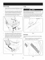
bracketsbeforepivotingthe handleupward.Referto Figure14.
a.
Placethespeedselectorshift leverinthe F6position.
b.
Cutthe cabletiesecuringthe two piecechutecrankto the
lowerhandle.Thecabletie is usedforshippingpurposes.
Removethe upperwingknobandcarriagebolt from each
sideofthe lowerhandle.Pullupon upperhandleasshown
in Figure1.Alignupperhandlewith the lowerhandle.Again,
makecertainthe springsat the lowerendof the augerand
drivecablesaresecurelyhookedinto theirrespective
actuatorbrackets.Also,removeanyrubberbandssecuring
the cablesto thewing nuts.
Removethe hairpinclip fromthe spiralcontrolasshowninA
ofFigure3.
of
Insertthe chutedirectionalcontrolrodinto the fitting on the spiralcontrol
asseeninBofFigure3.
3.
Securewiththe hairpinclip previouslyremoved.SeeFigure3.
F"
Figure1
2.
a.
Securethe supportbracket,upperhandleandlowerhandlewith the
two wingknobsandcarriageboltsremovedearlier.SeeFigure2.
Figure3
7
ChuteAssembly
Set-Lip
ChuteClean-OutTool
Removelocknutsandscrewssecuringoneof the flangekeepersto the chute
assembly.
Loosenthe fastenersof the othertwo flangekeepers.SeeFigure
4.
2.
Placechuteassemblyontochutebaseasshownin Figure5.Makesurethat
the chutenotchesengagewith the spiralendofchutedirectionalcontrol,
andthe two flangekeepersarebeneaththe flangeonthe chutebase.
3.
Secureflangekeeperremovedearlierwith locknutsandscrews.Tighten
downnutssecuringthe othertwo flangekeepers.SeeFigure4.
Neveruseyourhandsto clearacloggedchuteassembly.
Shutoffengine and
remainbehindhandlesuntilall movingpartshavestoppedbeforeusingthe
clean-outtool to clearthe chuteassembly.
Achuteclean-outtool isfastenedto the top of the augerhousingwitha mounting
clip.SeeFigure6. Thetool is designedto clearachuteassemblyof iceandsnow.
Thisitem isfastenedwith acabletie at the factoryforshippingpurposes.
Youmay
cut thecabletie at thistime.
Clean-outTool
!, //
/
i/
J
Figure4
4.
If not alreadydone,slipthe cablesthat runfromthe handlepanelto the
dischargechuteinto the cableguideon topof the engine.SeeFigure5.
5.
Normallythecabletiesholdingthesteeringcablesagainstthe handleare
looselyinstalledon eachsideof the lowerhandleatthe factory.Pullthe
cabletiestight to secure.Cutthe excessfrom the endsof cableties.
Figure6
Drift Cutters
Thesnowthrowerdrift cuttersaremountedinvertedat the factoryforshipping
purposes.
1.
Removethe fourwingknobs(two on eachside)andcarriagebolts. Place
drift cutterin uprightpositionandre-secure.SeeFigure7.
\
ii
Figure5
J
Figure7
8
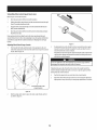
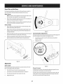
ShearPins
AddingFuel
A pairof replacement
augershearpinsandbowtiecotter pinshavebeenincluded
with yoursnowthrower.Thereareholesprovidedinthe plasticdashpanelfor
convenientstorageof the shearpins.Pushthe pinsthroughthe holesinthe dash
panelandsecurewith the bow-tiecotterpins.SeeFigure8.
Useextremecarewhenhandlinggasoline.Gasolineisextremelyflammableand
the vaporsareexplosive.Neverfuel the machineindoorsor whiletheengineis
hot or running.Extinguishcigarettes,cigars,pipesandothersourcesof ignition.
Alwayskeephandsandfeetclearof equipmentmovingparts.Donot usea
pressurized
startingfluid.Vaporsareflammable.
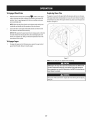
1.
Cleanaroundfuelfill beforeremovingcapto fuel.
2.
Afuel levelindicatoris locatedinthe fuel tank.Filltank untilfuel reachesthe
fuel levelindictor,Figure9. Becarefulnot to overfill.
@
Fnel LevelIndicator
TopView
Figure8
Tire Pressure(Pneumatic Tires)
Underanycircumstance
do notexceedmanufacturer'srecommended
psi.Equal
tire pressure
shouldbemaintainedatall times.Excessive
pressurewhenseating
beadsmaycausetire/rim assemblyto burstwith forcesufficientto causeserious
injury.Referto sidewalloftire forrecommended
pressure.
Figure9
Thetirescanbeover-inflatedforshippingpurposes.Checkthe tire pressure
beforeoperatingthe snowthrower. Referto the tire sidewall for manufactures's
recommended
psianddeflate(orinflate)the tires asnecessary.
Checking Oil Level
NOTE:Equaltire pressureisto be maintainedatall timesfor performancepurposes.
Theengineisshippedwith oil inthe engine.Youmust,however,checkthe oil
levelpriorto operatingthe snowthrower.Runningthe enginewith insufficient
oil cancauseseriousenginedamageandvoidthe enginewarranty.
FuelRecommendations
Useautomotivegasoline(unleaded
or low leadedto minimizecombustionchamber
deposits)with aminimumof87octane.Gasoline
with upto 10%ethanolor 15%MTBE
(MethylTertiaryButylEther)canbeused.Neveruseanoil/gasolinemixtureor dirty
Someengineswill havea quarter-turnoil fill/dipstickcap,othersmayhavea
gasoline.Avoidgettingdirt,dust,orwaterinthefueltank.DONOTuseE85gasoline.
threadedoil fill/dipstickcap.Followthe instructions
nextthatapplyto yourengine
Refuelinawell-ventilatedareawiththe enginestopped.Donot smokeor
model.
allowflamesor sparksinthe areawherethe engineis refueledor where
gasolineisstored.
Donot overfill the fueltank.Afterrefueling,makesurethe tankcapisclosed
properlyandsecurely.
Becarefulnot to spillfuel whenrefueling.Spilledfuel or fuelvapormay
ignite.If anyfuel isspilled,makesurethe areais dry beforestartingthe
engine.
Avoidrepeatedor prolongedcontactwith skinor breathingofvapor.
9
CheckingOil Levelon Engineswith Quarter-TurnOil
CheckingOil Levelon Engineswith threaded Oil Fill
Fill Caps
Caps
NOTE:Besuretocheckthe engineon alevelsurfacewith the enginestopped.
NOTE:Besureto checkthe engineona levelsurfacewith theenginestopped.
Toavoidenginedamage,it is importantto:
Toavoidenginedamage,it isimportantto:
Checkoil levelbeforeeachuseandevery5operatinghourswhenengineis
warm.Checkoil levelmorefrequentlyduringenginebreak-in.
Checkoil levelbeforeeachuseandevery5 operatinghourswhenengineis
warm.Checkoil levelmorefrequentlyduringenginebreak-in.
Keepoil levelbetween"H" and"L" markson dipstick.SeeFigure10.
Keepoil levelbetween"H"and"L" marksondipstick.SeeFigure11.
Besureoil fill cap/plugistightenedsecurelywhenchecking.
Besureoil fill cap/plugistightenedsecurelywhenchecking.
1.
Removethe oil filler cap/dipstkkandwipethe dipstickclean.SeeFigure10.
1.
Removethe oil filler cap/dipstkkandwipethe dipstickclean.SeeFigure11.
2.
Insertthe cap/dipstkkinto the oil filler neck,andtighten the capuntil
seated.
2.
Insertthe cap/dipstkkintothe oil filler neck,restingonthe threads,but do
not tighten.
3.
Removethe oil filler cap/dipstkk.Ifthe levelis low,slowlyaddoil until oil
levelregistersbetweenhigh(H)andlow (L),Figure10.
3.
Removethe oil filler cap/dipstick.If the levelislow,slowlyaddoil until oil
levelregistersbetweenhigh (H)andlow (L),Figure11.
4.
Replace
andtightencap/dipstkkfirmly beforestartingengine.
4.
Replace
andtighten cap/dipstickfirmly beforestartingengine.
NOTE:Donotoverfill.Overfillingwith oil maycausesmoking,hardstarting,or
sparkplugfouling.
NOTE:Donot overfill.Overfillingwithoil maycausesmoking,hardstarting,or
sparkplugfouling.
NOTE:DONOTallowoil levelto fall belowthe"L" markon thedipstick.Doingso
mayresultinequipmentmalfunctionsor damage.
NOTE:DONOTallowoil levelto fallbelowthe"L"markonthe dipstick.Doingso
mayresultinequipmentmalfunctionsor damage.
NOTE:Tochangethe oil on yourengine,seethe MaintenanceSectionofthe engine
operator'smanualincludedwith the snowthrower.
NOTE:Tochangethe oil onyourengine,seethe MaintenanceSectionof the engine
operator'smanualincludedwith the snowthrower.
Figure10
Figure
11
10
Adjustments
Auger and Drive Control Cables
SkidShoes
Priorto operatingyoursnowthrower,carefullyreadandfollowall instructions
below.Performall adjustmentsto verifyyoursnowthrowerisoperatingsafely
andproperly.
Itis not recommended
that youoperatethissnowthroweron gravelasit can
easilypickup andthrowloosegravel,causingpersonalinjury or damageto the
snowthrowerandsurroundingproperty.
TestingAugerDriveControl
Thesnowthrowerskidshoesareadjustedupwardat the factoryfor shipping
purposes.
Adjustthemdownwardpriorto operatingthe machine.
Forclosesnowremovalon asmoothsurface,adjustthe skidshoessothatthe shave
plateon the bottomof the augerhousingisjust offthe ground.
Whenthe augercontrolis releasedandin the disengaged
"up" position,the cable
shouldhaveverylittle slack,but shouldNOTbetight. Referto Figure13for location
of controls.
F
Adjustthe skidshoesto alowerpositionto raisethe shaveplateoffthe ground
whenclearingunevenareas,suchasa ribbontype drivewayor agraveldriveway
ChuteTiltControl _
_
2_
Auge,
Shift Lever
n.
,, ve
H- ---coot,u,
NOTE:Ifyouchooseto operatethe snowthroweron agravelsurface,keepthe skid
shoesin positionfor maximumclearancebetweenthe groundandthe shaveplate.
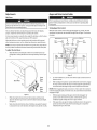
Toadjust the skid shoes:
1.
Adjustskidshoes
byloosening
thesix(threeoneachside)hexnutsand
carriage
boltssecuring
theskidshoes
totheaugerhousing.Refer
toFigure
12.
Auger
d___
Drive
J
Figure13
Lower
Shave
Plate
ShavePlate
Raise
Shave
.
Plate
1.
Inawell-ventilatedarea,startthe snowthrowerengineasinstructedinthe
Operationsection.
2.
Whilestandinginthe operator'sposition(behindthesnowthrower),engage
the augercontrolandallowthe augerto remainengagedfor approximately
ten secondsbeforereleasingthe augercontrol.Repeatthisseveraltimes.
NOTE: Whenengagingthe auger,you mayheara"chirp"sound.Thisis normal,it
is the beltengagingthe pulley.Asthe belt wears,thissoundwill not beheardwhen
engagingthe auger.
j
Figure12
2.
Whileobservingthe distancebetweenthe shaveplateandthe ground,
adjustthe skidsshoesup or downto achievethe desiredshaveplateheight.
SeeFigure12.
3.
Makecertainthe entirebottomsurfaceof skidshoesareagainsttheground
to avoidunevenwearonthe skidshoes;thentightennutsandboltssecurely.
11
3.
With the enginerunningandthe augercontrolin thedisengaged"up"
position,walkto the front of the machine.Confirmthatthe augerhas
completelystoppedrotatingandshowsnosignsof motion.
4.
Ifthe augershowsanysignsof rotating,immediatelyreturntothe operator's
positionandshutoff the engine.Waitfor all movingpartsto stop before
readjustingthe augercontrolcable.
Testing
Whee{ Dr}reContro{
& SpeedSelector
Lever
Refer
toFigure
13for
{ocation
ofcontro{s.
I.
Movethespeed
selector
shift
{ever
into
sixth
(6)
posit{on.
2.
Withthewheeldrivecontro{released,
pushthesnowthrowerforward,thenpull
it back.Themachineshouldmovefreely.
3.
Engage
thedrivecontrolandattempttomovethemachinebothforwardand
back,resistance
shouldbefelt.
4.
Movethespeedselector
shiftleverintothefastreverse
(R2)positionandrepeat
theprevious
twosteps.
Ifyouexperienced
resistance
rollingthe unit,eitherwhenrepos{tioning
thespeed
selector
shiftleverfrom6 toR2orwhenattemptingto movethe machine
withthedrive
controlreleased,
adjustthedrivecontrolimmediately.
SeeAdjustingDriveandAuger
Controls.
J
Figure15
Adjusting
Whee{Dr}re
& Auger(ontro{s
1.
Ifadjustingthe drivecable,threadthe locknut outward(downthe coupler
towardsthe endof the thread)to lengthenthe cableandallowthe un{tto
movefreelywhenthe control{sreleased.
Threadthe locknut inward(upthecouplertowardsthe cable)to shortenthe
cableto reduceslippageandpreventthe mach{nefrom beingeas{lymoved
w{th the dr{vecontrolengaged.
Frombeneath
thehandle,
pulldownward
ontheappropriate
cableand
unhook
thespringfoundontheendofthecablefromitsrespective
actuator
bracket.
Refer
to Figure
14.
Donotover-tightenthe cable.Over-tightening
maypreventthe augershaftfrom
disengaging
andcompromise
the safetyof thesnowthrower.
Ifadjustingthe augercable,threadthe locknut downthe couplertowardsthe
endofthe threadto lengthenthe cableasnecessary
to stopthe augershaftfrom
turningwhenthe controlisreleased.
......
Rearwardmostholeofthe
actuatorbrackets
Figure14
2.
S{{dethe springup the cab{eto exposethe cab{ecoup{erthreadsand{ock
nut.Referto Figure15.
12
4.
Reattach
the springto the rear-mostholeinthe actuatorbracket.
5.
Repeatthe wheeldriveandaugercontrolteststo verifyproperadjustment.
Repeatpreviousstepsif necessary
to attainproperadjustmentofeachcable.
f
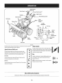
SpeedSelector
Drive
"
Chute ControF M
AugerControl
Headlight
Wheel SteeringControl
ChuteAssembly
DriftCutters
Chute
Clean-outTool
Control
\
Oil Filler
Cap/Dipstick
PrimerKey
Electric
Start
Button
Electric
Outlet
Augers
.%o,
Recoil Starter
Handle
Ch°kTh
Skid Shoes
Oil Drain
16
Figure
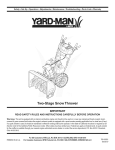
Nowthatyouhavesetupyoursnowthrower,
it'simportant
tobecome
acquainted ChokeControl
with itscontrolsandfeatures.Referto Figure16.
SpeedSelector Shift Lever
5
Thechokecontrolisfoundonthe rearof theengineandis
activatedbyrotatingthe knobcounter-clockwise.
Activating
the chokecontrolclosesthe chokeplateon the carburetor
andaidsinstartingthe engine.
4
Key
3
Thekeyisasafetydevice.It mustbefully inserted
inorder
for theengineto start. Removethe keywhenthe snow
throwerisnot in use.
6
Thespeedselectorshift leverislocatedonthe right sideof the
handlepanel.Placethe speedselectorshift leverintoanyof eight
positionsto controlthe directionof travelandgroundspeed.
Forward
Yoursnowthrowerhassixforward(F)speeds.Positionone(1)is
the slowestandpositionsix(6)isthe fastest.
Reverse
t2
F1
Yoursnowthrowerhastwo reverse(R)speeds.One(1)isthe slower
andtwo (2)isthe faster.
R1
NOTE:Donot turn the keyinanattempt to startthe engine.
Doingsomaycauseit to break.
R2
MeetsANSISafety Standards
CraftsmanSnowThrowersconformtothe safetystandardof the AmericanNationalStandards
Institute(ANSI)
13
ThrottleControl
GasCap
Unthreadthe gascapto addgasolineto the fueltank.
==-,.-
OUDrain
Engineoil canbedrainedthroughthe oil drain.
Thethrottlecontrolislocatedon the rearofthe engine.Itregulatesthe speedof the
engineandwill shutoffthe enginewhenmovedinto the STOP
position.
DriveControl/Auger Control Lock
/
Primer
DRIVE
CONTROL
Depressing
the primerforcesfueldirectlyintothe engine'scarburetorto aidin
cold-weatherstarting.
0U
Fili
Engine
oil levelcanbe checkedandoil addedthroughthe
[ _,,_.J__
,.
oil fill.
RecoilStarter Handle
J
Thishandleisusedto manuallystartthe engine.
ElectricStarterButton
Pressing
the electricstarterbuttonengagesthe engine'selectricstarterwhen
pluggedinto a 120Vpowersource.
ElectricStarterOutlet
Requires
the useof athree-prongoutdoorextensioncordanda 120Vpowersource/
walloutlet.
Augers
Thewheeldrivecontrolislocatedon the righthandle.Squeeze
the controlgrip
againstthe handleto engagethe wheeldrive.Release
to stop.TheWheeldrive
controlalsolocksthe augercontrolsoyoucanoperatethe chutedirectionalcontrol
without interruptingthe snowthrowingprocess.If the augercontrolisengaged
simultaneouslywith the wheeldrivecontrol,the operatorcanreleasethe auger
control(onthe left handle)andthe augerswill remainengaged.Release
both
controlsto stoptheaugersandwheeldrive.
NOTE:Alwaysreleasethe wheeldrivecontrolbeforechangingspeeds.Failureto do
sowill resultinincreasedwearon yourmachine'sdrivesystem.
Two-waychute Control"
Whenengaged,the augersrotateanddrawsnowinto the augerhousing.
Thetwo-waychute-pitchcontrolislocatedon the left sideof the handlepaneland
is usedto controlthe distanceofsnowdischargefromthe chute.
ChuteAssembly
Tochangethe upperchuteangletocontrolthe distancethat snowisthrown,
pivotthe leverforwardor backward.
Snowdrawninto the augerhousingisdischarged
out the chuteassembly.
AugerControl
f
Movethe leverforwardto pivotthe upperchutedownandreducethe
distancesnowisthrown.
AUGER
CONTROL
Movethe leverrearwardto pivot the upperchuteupwardandincrease
the
distancesnowisthrown.
S
CHUTE
DISCHARGE
LEFT
DIRECTIONAL
CONTROL
DISDHARDE
1;
i
CHUTE TILT
DOWN
J
Theaugercontrolislocatedon the left handle.Squeeze
the controlgripagainstthe
handleto engagethe augersandstartsnowthrowingaction.Release
to stop.
CHUTE TILT
UP
14
J
NOTE:
Toincrease
ordecrease
thetension
onthetwo-waychutecontrol,tightenor
loosen
thewingknobonthechuteassembly.
BeforeStarting Engine
ChuteDirectional Control
Read,understand,andfollow all instructionsandwarnings on the machine
and inthis manualbeforeoperating.
Thechutedirectionalcontrolis locatedonthe left sideofthe snowthrower.
Tochangethe directioninwhichsnowisthrown,crankclockwiseto
dischargeto the left andcounterclockwise
to dischargeto the right.
Oil
SkidShoes
Theunit wasshippedwith oil in the engine.Checkoil levelbeforeeachoperation
to ensureadequateoil inthe engine.Forfurther instructions,referto the Service&
Position
theskidshoes
based
onsurface
conditions.
Adjustupward
forhard-packed Maintenance
sectionof thismanual.
snow.
Adjustdownward
whenoperating
ongravelorcrushed
rocksurfaces.
NOTE:Besureto checkthe engineona levelsurfacewith theenginestopped.
Wheel Steering Controls
Theleft andrightwheelsteeringcontrolsarelocatedonthe undersideofthe
handles.Squeeze
the right controlto turn right;squeezethe left controlto turn left.
1.
Removethe oil filler cap/dipstickandwipethe dipstickclean.
2.
Insertthe cap/dipstickintothe oil filler neck,andtightenthe capturning
clockwiseuntil capisseated.
NOTE:Operatethe snowthrowerin openareasuntil youarefamiliarwith these
controls.
flOTE:Onsomeengines,a threadedscrewcapwill bepresentinsteadof
the quarterturn lockingcap.In the instanceof athreadedoil cap/dipstick,
DONOTscrewthecap/dipstickin to check.Checkthe oil byrestingthe cap/
dipstickonthe threads,but not screwingit in.
Headlight
Theheadlightis locatedinsideofthe handlepanel.
Drift cutters
Removethe oil filler cap/dipstick.If the levelislow,slowlyaddoil (5W-30,
with a minimumclassificationof SF/SG)
until oil levelregistersbetweenhigh
(H)andlow (L).
Thedrift cuttersaredesignedforusein deepsnow.Theiruseisoptionalfor normal
snowconditions.Maneuverthe snowthrowersothatthe cutterspenetratea high
standingsnowdrift to assistsnowfalling into the augersforthrowing.
flOTE:Donot overfill.Overfillingwithoil mayresultinenginesmoking,hard
startingorsparkplugfouling.
Replace
andtighten cap/dipstickfirmly beforestartingengine
Clean-OutTool
Gasoline
Thechuteclean-outtool isconvenientlyfastenedto the rearofthe augerhousing
with amountingclip.Shouldsnowandicebecomelodgedin the chuteassembly
duringoperation,proceedasfollowsto safelycleanthe chuteassemblyandchute
opening:
Useextremecarewhen handlinggasoline.Gasolineisextremely flammable
andthe vaporsare explosive.Neverfuel the machineindoorsor while the
engine ishot or running. Extinguishcigarettes,cigars,pipesandother
sourcesof ignition.
Neveruseyour handsto cleara cloggedchuteassembly.Shutoffengine
and remain behind handlesuntil all moving partshavestoppedbefore
unclogging.
1.
Release
boththe AugerControlandthe Wheeldrivecontrol.
2.
Stopthe enginebyremovingthe key.
3.
Removethe clean-outtoolfrom the clipwhichsecures
it to the rearof the
Useautomotivegasoline(unleadedor low leadedto minimizecombustionchamber
deposits)with aminimumof 87octane.Gasolinewith upto 10%ethanolor 15%
MTBE
(MethylTertiaryButylEther)canbeused.Neveruseanoil/gasolinemixture
or dirty gasoline.Avoidgetting dirt,dust,or waterinthefuel tank.DONOTuseE85
gasoline.
Refuelinawell-ventilatedareawith the enginestopped.Donot smokeor
allowflamesor sparksinthe areawherethe engineis refueledor where
gasolineisstored.
augerhousing.
4.
Usetheshovel-shaped
endofthe clean-outtoolto dislodgeandscoopany
snowandicewhichhasformedinandnearthe chuteassembly.
5.
Refasten
theclean-outtooltothe mountingclipon therearof theauger
housing,reinsertthe keyandstartthesnowthrower'sengine.
6.
Donot overfill the fueltank.Afterrefueling,makesurethe tankcapisclosed
properlyandsecurely.
Becarefulnot to spillfuel whenrefueling.Spilledfuelor fuel vapormay
ignite.If anyfuel isspilled,makesurethe areaisdry beforestartingthe
engine.
Whilestandinginthe operator'sposition(behindthe snowthrower),engage
the augercontrolfor afewsecondsto clearanyremainingsnowandicefrom
the chuteassembly.
Avoidrepeatedor prolongedcontactwith skinor breathingofvapor
1.
Cleanaroundfuelfill beforeremovingcapto fuel to preventdebrisfrom
enteringfuel tank..
2.
Afuel levelindicatoris locatedinthe fuel tank.Filltank until fuelreachesthe
fuel levelindictor.SeeFigure10inset.Becarefulnot to overfill.
15
Starting The Engine
Alwayskeephandsandfeet dear of moving parts. Donot usea pressurized
starting fluid. Vaporsareflammable.
NOTE:
Allow the engineto warmup forafew minutesafter starting.The
enginewill not developfull poweruntil it reachesoperatingtemperatures.
6.
Asthe enginewarms,slowlyrotatethe chokecontrolto the RUNposition.If
the enginefalters,restartengineandrunwith chokeat half-chokeposition
for ashortperiodof time,andthenslowlyrotatethechokeinto the RUN
position.
7.
Afterengineisrunning,disconnectpowercordfrom electricstarter.When
disconnecting,
alwaysunplugthe endat the walloutlet beforeunplugging
the oppositeendfromthe engine.
RecoilStarter
Makecertainboththe augercontrolandwheeldrivecontrolarein the
disengaged(released)
position.
Donot pull the starter handle whilethe engine running.
Insertkeyintoslot.Makesureit snapsinto place.Donot attemptto turn the
key.
NOTE:
Theenginecannotstartwithout the keyfullyinsertedinto the
ignitionswitch.
Eiectrk Starter
Theoptional e[ectrk starter isequipped with agrounded powerplug, and
isdesignedto operate on an extensioncord ratedfor 15ampsat 125volts,
groundedandratedfor outdoor useusing 120volt AChouseholdcurrent,it
mustbe usedwith a properly groundedthree-prong receptacleat ai[ times
to avoid the possibility of eiectrk shock.Follow all instructionscarefully
prior to operating the electricstarter.
1.
Movethrottlecontrolto FAST
(rabbit)_1
2.
Movechoketo the CHOKE
I,,1¢1position(coldenginestart).Ifengineis
warm,placechokeinthe RUNposition.
3.
Pushprimerthreetimes,makingsureto coverventholewhenpushing.
Ifengineiswarm,pushprimeronlyonce.Alwayscovervent holewhen
pushing.Coolweathermayrequireprimingto berepeated.
4.
Pullgentlyonthe starterhandleuntil it beginsto resist,thenpullquicklyand
forcefullyto overcome
the compression.
Engineshouldstart.Donot release
the
handleandallowit to snapback.ReturnropeSLOWLY
to originalposition.If
required,repeatthisstep.
5.
Asthe enginewarms,slowlyrotatethe chokecontrolto the RUNposition.If
the enginefalters,restartengineandrunwith chokeat half-chokeposition
for ashortperiodof time,andthenslowlyrotatethechokeinto the RUN
position.
Determinethatyourhome'swiring isathree-wiregroundedsystem.Askalicensed
electricianif youarenot certain.
position.
If youhaveagroundedthree-prongreceptacle,
proceedasfollows:
1.
Plugan extensioncordintothe outlet locatedonthe engine'ssurface.Plug
the otherendof extensioncordinto athree-prong120-volt,grounded,AC
outletina well-ventilatedarea.
Toavoid unsupervised
engine operation, neverleavethe machine
unattended with the engine running.Turnthe engine off after useand
removekey.
Stopping The Engine
Theextensioncordcanbe any length, but must be ratedfor 15ampsat 125
volts, groundedand ratedfor outdoor use.
2.
Movethrottle controlto FAST
(rabbit)_
3.
Movechoketo the CHOKE
position [,jC[ (coldenginestart).
Afteryouhavefinishedsnow-throwing,runengineforafew minutesbefore
stoppingto help dryoff anymoistureonthe engine.
1.
position.
NOTE:Ifthe engineisalreadywarm,placechokecontrolinthe RUNposition
insteadof CHOKE
12¢I position.
4.
5.
Movethrottlecontrolto STOP
(_
ine. Backfireor en
Pushprimerthreetimes(3x),makingsureto coverventholein primerbulb
whenpushing.Ifengineiswarm,pushprimeronlyonce.Alwayscovervent
holewhenpushing.Coolweathermayrequireprimingto berepeated.
Pushstarterbuttontostart engine.Oncethe enginestarts,immediately
releasestarterbutton.Electricstarterisequippedwith thermaloverload
protection;systemwill temporarilyshut-downtoallowstarterto coolif
electricstarterbecomes
overloaded.
Toprolong starter life, useshort starting cycles(5secondsmaximum,then
wait one minute).
16
position.
occur.
2.
Remove
the key.Removing
thekeywill reducethepossibility
of unauthorized
startingoftheenginewhileequipmentisnotinuse.Keepthekeyinasafeplace.
Theenginecannotstartwithoutthekey.
3.
Wipeall snowandmoisturefromthe areaaroundthe engineaswellasthe
areainandaroundthe wheeldrivecontrolandaugercontrol.Also,engage
andreleasebothcontrolsseveraltimes.
ToEngageWheel Drive
1.
With thethrottle controlinthe Fast(rabbit)_j_
ReplacingShearPins
Theaugersaresecuredtothe spiralshaftwith shearpinsandbow-tiecotterpins.
Ifthe augershouldstrikeaforeignobjector kejam, the snowthrowerisdesigned
sothatthe pinsmayshear.Ifthe augerswill notturn, checkto seeif the pinshave
sheared.SeeFigure17.
position,movespeed
selectorleverinto oneof the sixforward(F)positionsor two reverse(R)
positions.Selecta speedappropriateforthe snowconditionsanda pace
you'recomfortablewith.
flOTE:Whenselectinga DriveSpeed,usethe slowerspeedsuntil youare
comfortableandfamiliarwith the operationofthe snowthrower.
2.
Squeeze
the drivecontrolagainstthe handleandthe snowthrowerwill
move.Release
it anddrivemotionwi[[ stop.
NOTE:NEVER
repositionthe speedselectorlever(changespeedsor direction
oftravel)without first releasingthe drivecontrolandbringingthe snow
throwerto acompletestop.Doingsowi[[ resultin prematurewearto the
snowthrower'sdrivesystem.
ToEngageAuger
1.
Toengagethe augerandstart throwingsnow,squeeze
the augercontrol
againstthe left handle.Release
to stopthe augers.
Figure
17
NOTE:Twoextrashearpinsaresuppliedin the manualbag.
NEVER
replacethe augershearpinswith anything other than OEMPart No.
738-04155replacementshearpins. Anydamageto the augergearboxor
other componentsasa result of failing to do sowill NOTbe coveredbyyour
snowthrower'swarranty.
Always
turnoffthesnowthrower's
engineandremove
thekeypriortoreplacing
shearpins.
17
MAINTENANCE
SCHEDULE
Beforeperforming
anytypeofmaintenance/service,
disengage
allcontrolsandstop
theengine.Waituntilallmovingpartshavecometoacompletestop.Remove
the key
topreventunintended
starting.Alwayswearsafetyglasses
duringoperation
or while
performinganyadjustments
or repairs.
EachUse
Followthe maintenanceschedulegiven below.Thischart describesservice
guidelinesonly. Usethe ServiceLogcolumnto keeptrackofcompleted
maintenancetasks.Tolocatethe nearestSearsServiceCenteror to schedule
service,simplycontactSearsat 1-800-4-MY-HOME
®.
1.
Engineoil level
1.
Check
2.
Looseor missinghardware
2.
Tightenor replace
3.
Unitandengine.
3.
Clean
1st5- 8 hours
1.
Engineoil
1.
Change
25 hours
1.
Engineoilf
1.
Change
2.
Controllinkagesandpivots
2.
Lubewith light oil
50hours
1.
Engineoil
1.
Change
Annuallyor 100hours
1.
Sparkplug
1.
Cleanandre-gap,or elsereplacewith
new plug.
BeforeStorage
1.
Fuelsystem
1.
Runengineuntil it stopsfrom lackof fuel
or adda gasolineadditiveto the gasin
the tank.
f Underheavyloador inhigh temperatures
ENGINEMAINTENANCE
Checking
Engine
Oil
Beforelubricating,repairing,or inspecting,
disengageall controlsandstop
engine.Wait until all movingpartshavecometo a completestop.Removethe
[keyto preventun ntendedf r ngof the eng he.
NOTE: Check the oil level before each use to be sure correct oil level
is maintained.
Whenaddingoil to the engine,referto viscositychartbelow.Engineoil capacity
isapproximately37ounces.Donot over-fill.Usea4-stroke,or anequivalenthigh
detergent,premiumquality motoroil certifiedto meetor exceedU.S.automobile
manufacturer'srequirementsforserviceclassificationSG,SF.Motoroilsclassified
SG,SFwill showthisdesignationon thecontainer.
1.
Removethe oil filler cap/dipstickandwipethe dipstickclean.
2.
Insertthe cap/dipstickinto the oil filler neck,but do not screwit in.
J
Figure18
NOTE:Onsomeengines,a threadedscrewcapwill bepresentinsteadof
the quarterturn lockingcap.Inthe instanceof athreadedoil cap/dipstick,
DONOTscrewthe cap/dipstickinto check.Checkthe oil by restingthe cap/
dipstickon the threads,but not screwingit in.
4.
Changing
Engine
Oil
NOTE:Changethe engineoil afterthe first 5hoursof operationandoncea
seasonor every50 hoursthereafter.
Removethe oil filler cap/dipstick.Iflevelislow,slowlyaddoil until oil level
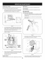
registersbetweenhigh(H)andlow (L).SeeFigure18.
1.
Drainfuelfrom tankbyrunningengineuntil the fuel tank isempty.Besure
fuel fill capissecure.
Replace
andtightencap/dipstickfirmly beforestartingengine.
2.
Placesuitableoil collectioncontainerunderoil drainplug.
3.
Removeoil drainplug.SeeFigure19.
18
f
Ifthe engine hasbeenrunning,the muffler will be very hot. Becareful not
to touchthe muffler.
NOTE:Checkthe sparkplugonceaseasonor every25hoursof operation.Change
the sparkplugonceaseasonor every100hours.
Toensureproperengineoperation,the sparkplug mustbeproperlygappedand
freeof deposits.
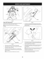
1.
Removethe sparkplug bootanduseasparkplug wrenchto removethe
plug.SeeFigure20.
Oil Drain
Plug
SparkPlug
Figure19
4.
Tipengineto drainoil intothecontainer.Usedoil mustbedisposedofat a
propercollectioncenter.
Usedoil isahazardouswaste product. Dispose
of usedoil properly. Donot
discardwith householdwaste. Checkwith your localauthorities or Sears
ServiceCenterfor safedisposal/recyclingfacilities.
5.
Reinstallthe drainplugandtightenit securely.
6.
Refillwith the recommended
oil andcheckthe oil level.SeeRecommended
Spark Plug Boot
Oil Usagechart.Theengine'soil capacityis37ounces.
Figure20
Visuallyinspect
the sparkplug.Discardthe sparkplug ifthereis apparent
wear,or if the insulatoris crackedor chipped.Cleanthe sparkplugwith a
wire brushif it isto bereused.
DONOTusenon-detergent oil or 2-strokeengine oil. It could shortenthe
engine'sservicelife.
Measurethe plug gapwith afeelergauge.Correctasnecessary
bybending
sideelectrode.SeeFigure21.Thegapshouldbesetto .02-.03inches(0.600.80mm).
y.t,oti'o
F
2
3
(%-400 -200 0o 200 400
(°c)
7.
-300 -200 -100 0o
Reinstallthe oil filler cap/dipsticksecurely.
Thoroughlywashyour handswith soapandwater assoonaspossibleafter
handling usedoil.
Checking
1..030 (.76 mm) Gap
2. Electrodes
Spark Plug
3.
Porcelain
J
Figure21
DONOTcheckfor sparkwith sparkplug removed.DONOTcrankengine with
sparkplug removed.
19
4.
Checkthatthe sparkplug washerisingoodconditionandthreadthe spark
plugin byhandto preventcross-threading.
4.
5.
Afterthe sparkplug isseated,tightenwith asparkplugwrenchto compress
the washer.
At leastonceaseasongreasethe wheelaxlewith Arcticgrease,part number
737-0318.
Thegreasefitting islocatedonthe wheelaxletubebehindthe
wheelaxlesupportbracket.
Wheels
At leastonceaseason,removebothwheels.Cleanandcoatthe axleswith a
NOTE:
Wheninstallinga newsparkplug,tighten1/2-turnafter the sparkplug seats
to compress
the washer.Whenreinstallingausedsparkplug,tighten1/8-to 1/4-turn
afterthe sparkplugseatsto compressthe washer.
multipurposeautomotivegreasebeforereinstallingwheels.
Chute
Directional
Control
Onceaseason,lubricatethe eyebolt bushingandthe spiralwith 3-in-1oil.
Auger Shaft
' hot andcan dama_
At leastonceaseason,oneat atime,removeall ofthe shearpinsfrom the auger
shaft.Spraylubricantinsidethe hubof eachaugerspiralassemblyandaroundthe
spacersonthe augershaft.
me.
Carburetor Adjustment
Thecarburetorisnot useradjustable.ContactSearsParts& Repairforadjustment.
Greasefittings canalsobefoundat eachendofthe augershaft.Lubricatewith a
greasegunonceaseason.SeeFigure23.
Lubrication
Gear Case
Drive and Shifting
Mechanism
Atleastonceaseasonor afterevery25hoursof operation,removerearcover.
Lubricateall chains,sprockets,gears,bearings,shafts,andthe shiftingmechanism.
Useengineoil or aspraylubricant.Referto Figure22.
NOTE:Torelievepressure,removethe vent plugbeforelubricatingthe gearcase.
SeeFigure23. Failureto do socouldresultindamageto the gearcaseseals.
Augers
NOTE:
Beforetippingthe uniton the front housing,runthe fuel tankemptysofuel
doesnot leakout of the fuel cap.
1.
Carefullypivotthe snowthrowerupandforwardsothat it restsonthe auger
housing.
2.
Removethe framecoverfrom the undersideof the snowthrowerby
removingthe self-tappingscrewswhichsecureit. Referto Figure27.
3.
Theaugergearcaseisequippedwith agreasefitting. Lubricatewith greaseoncea
season(orderpartnumber737-0168).SeeFigure23.
Eachof the augerspiralassemblies
issecuredto the spiralshaftwith ashearpin and
cotterpin. If theaugershouldstrikeaforeignobjector icejam, the snowthroweris
designedsothatthe pinsmayshear.
1.
Ifaugersdonot turn, checkto seeif pinshavesheared.
2.
Replace
the pinsif needed.Tworeplacement
shearpinsandcotterpins
havebeenprovidedwith thesnowthrower.Sprayanoil lubricantintoshaft
beforeinsertingnewpinsandsecuringwith newcotterpins.SeeFigure23.
Applya lightcoatingof engineoil (or3-in-1oil) to the hexshaft.SeeFigure
22.
f
NOTE:Becarefulnot to get anyoil onthe aluminumdriveplateor rubber
frictionwheel.Doingsowill hinderthesnowthrower'sdrivesystem.Wipe
offany excessor spilledoil.
ShearPins
f
Bow-fiePins
Vent Plug
Spacers
Whe=el
Figure23
Figure22
20
GreaseFitting
;;
Shave Plate and Skid Shoes
Theshaveplateandskidshoeson the bottomofthe snowthroweraresubjectto
wear.Theyshouldbecheckedperiodicallyandreplacedwhennecessary.
Skid Shoes
NOTE:Theskidshoeson thismachinehavetwo wearedges.Whenoneside
wearsout,theycanberotated180° to usethe otheredge.
1.
Removethe sixcarriageboltsandhexnutsthatsecurethe two skidshoesto
the sidesofthe augerhousing.Referto Figure24.
2.
Positionthe newskidshoesandsecurewith the carriageboltsandhexnuts.
Makecertainthe skidshoesareadjustedto belevel.
Shave
Plate
1.
Removethe hexnutsandcarriageboltsthat securethe shaveplatetothe
bottomofthe housing.Referto Figure24.
2.
Removethe rearmosthexnut andcarriagebolt securingthe backof each
skidshoeto the sidesofthe housing.Loosenthe fourremaininghexnuts
securingthe skidshoes.
3.
4.
J
Figure25
Slidethe shaveplateout ofthe off-setslotat the bottomof the housing,and
from betweenthe skidshoesandsidepanelsofthe housing.
With the mountingholestowardthe backof the unit, slidethe newshave
plateinto positionandsecurewiththe fastenersremovedpreviously.
Chute
Bracket
Adjustment
Ifthe spiralatthe bottomof the chutedirectionalcontrolisnotfully engagingwith
the chuteassembly,
the chutebracketcanbeadjusted.Todo so:
5.
Loosenthe two nutswhichsecurethechutebracketandrepositionit
slightly.SeeFigure26.
6.
Retightenthe nuts.
J
Figure24
Adjustments
J
Shift Cable
Figure26
If the full rangeof speeds(forwardandreverse)cannotbeachieved,referto the
Figure25andadjustthe shift cableasfollows:
Chute
1.
Placethe shift leverinthe fastestforwardspeedposition.
Thedistancesnowisthrowncanbeadjustedbyadjustingthe angleof the chute
assembly.Referto the Operationsectionforinstructions.
2.
Loosenthe hex nut onthe shift cableindexbracket.SeeFigure25.
3.
Pivotthe bracketdownwardtotake upslackinthe cable.
4.
Retightenthe hexnut.
Control
Theremotechutecontrolcableshavebeenpre-adjustedat the factory.Movethe
remotechuteleveronthe controlpanelforwardto pivot the upperchutedown;
movethe leverrearwardto pivotthe upperchuteup.
21
Wheel
drive
Skid
control
Referto theAdjustmentsectionof the Assemblyinstructionsto adjustthe wheel
drivecontrol.Tofurthercheckthe adjustment,proceedasfollows:
1.
Shoes
Referto the Assemblysectionfor instructions
onadjustingthe skidshoes.
Tire Pressure
Withthe snowthrowertippedforward(becertainto runthe fuel tankdry
beforetipping the unitforward),removethe framecoverunderneaththe
snowthrowerbyremovingthe self-tappingscrews.SeeFigure27.
Referto the Assemblysectionfor instructions
onadjustingthe tire pressure.
Belt replacement
f
Belt Removal
Preparation
1.
Removethechutecrankrodfrom thechutecrankassemblybyremovingthe
hairpinclip shownin Figure29.Movethe chutecrankrodawayfrom the
assemblyasshown.
2.
Removethreeself-tapscrewson bothsidesof the transmissionhousingas
showninFigure29.
f
Figure27
2.
Locatetheopeningbetweenthe axlesupportbracketandthe front frame
support(SeeFigure28).Lookingthroughthisopening,with the wheeldrive
controlreleased,theremustbeclearance
betweenthefriction wheeland
the driveplatein all positionsof the speedselectorlever.
3.
Withthe wheeldrivecontrolengaged,the frictionwheelmustcontactthe
driveplate.SeeFigure28.
f
Figure29
Removethe plasticbeltcover,locatednearthe engine,byremovingthe
threeself-tappingscrewsthat secureit. SeeFigure30.
f
Figure28
4.
5.
If thereisnofriction wheelclearance,or the frictionwheeldoesnot solidly
contactthe driveplate,re-adjustthe locknut on the lowerendof the drive
cablefollowingthe instructions
in theAssemblysection.
/
Reassemble
the framecover.
/
Figure30
Auger Control
Loosen
the boltshowninFigure31securing
the beltkeeperbracketandremove
theotherbolt.Pushthebeltkeeperandbracketupoff theenginepulley.
Referto theAssemblysectionforinstructions
on adjustingtheaugercontrolcable.
22
Loosen
z-fitting
Figure31
Auger Belt Replacement
Figure33
Removethe bow-tieclipandflat washerfrom the ferruleinorderto disconnect
the
augeridlerrodfromthe brakebracketassembly.
SeeFigure32.
Place
a blockofwoodunderneaththeaugerhousingasshownin Figure34
andseparate
augerhousingfromtheframebytiltingthe housingforwardand
pullingupthe handles.
NOTE:Makesurethat the locationof the ferruleon the augeridlerrodis
maintained.
HairpinClip
and Washer
Ferrule
Figure34
5.
Auger Idler Rod
\
Blockthe impellerwithapieceofwoodto preventitfromspinningandusea
1/2"wrenchto removethe hexscrewandflat washerfrom thecenterof the
pulleyonthe augerhousing.SeeAinFigure35.
Figure32
6.
1.
Slipthe augercontrolbelt (thefront belt)off the enginepulley.
2.
Pullthe brakebracketassemblytowardsthe cableguiderollerandunhook
the augercablez-fitting. SeeFigure33.
3.
Fromboth sidesof the the frameassembly,
usea 1/2" wrenchto remove
the threehextapscrewssecuringthe frameto the augerhousingassembly.
Referbackto Figure29.
NOTE:Donot removethe lower hexflangelocknut oneachside.
23
Liftthe brakebracketassemblyout of the pulleygroove(Bin Figure35)and
slidethe pulleyassemblyoffthe postsof the augerpulleyadapter(C)to
removethe oldbelt.
NOTE:Thepulleyadaptermayslideoff the augerinputshaftwhenremoving
the pulley.Useextracautionto ensurethe adapterdoesfall and/orget
damagedwhenremovingthe pulley.
Placethe newaugerbelt in theV-grooveof the augerpulleyand
placethe pulleyw/belt insidethe beltkeepers.
!
/
pter Post
Brake
%
\
Figure35
8.
J
Figure36
Turnthepulleyasnecessary
toalignitsthreeslotsapproximately
with the
postsof the pulleyadapter,thenpivotthe brakebracketassemblyawayfrom
the pulleygroove.Whilealigningthe pulleyslotsandadapterposts,push
the augerpulleyfullyontothe adapter.Referto Figure35.Ensurethe brake
puckof the brakebracketassemblyalignsandisfullyseatedinthe pulley
1.
Rollthedrivebeltoffthe lowerdrivepulley.
groove.
2.
Removethe beltfrom the enginepulley.
NOTE:If the pulleyadapterwasremovedwith the pulley,alignthe splines
of the pulleyadapterandaugerinputshaft,andpushthe pulleyandadapter
ontothe inputshaft.Referto Figure35.
3.
Installthe newbelt onthe pulleysinthe reverseorderandre-tensionwith
the idlerpulley.
4.
Reassemble
byperformingthe previousstepsinthe oppositeorderand
mannerof removal.
9.
Slidethe washerontothe hexscrewremovedearlierandapplyLoctite262to
the threadsofthe hexscrew.
10.
Insertthe hexscrewthroughthe pulleyassemblyandintothe threadsof
the inputshaft.Torquethe hexscrewto 250-325in.Ibs.to securethe auger
pulleyassemblyonthe inputshaft.
Pullthe idlerpulleyawayfrom the backsideof the drivebeltto relieve
the tension.SeeFigure36.
Slipthedrivebeltoff the idlerpulley.Carefullyreleasethe idlerpulley.
Changing Friction Wheel
Therubberon the frictionwheelissubjectto wearandshouldbechecked
periodically.Replace
the frictionwheelifanysignsof wearor crackingarefound.
11.
If alsoreplacingthe drivebelt, proceedto the "DriveBelt"instructions.If
not,repositionthe transmissionframebackontotheaugerhousing.
1.
Runthe unit'sfueltank dry beforeperformingStep2. Donot attemptto
pourfuel from theengine.
12.
Installthe drivebelton the enginepulley,re-connectthe augercable
z-fitting andaugeridlerrodferruletothe brakebracket.Reposition
and
securethe enginepulleybeltguard,andre-installthe belt cover.
2.
Tipthe snowthrowerupandforward,sothat it restson the housing.
3.
Removescrewsfrom the framecoverunderneaththe snowthrower(referto
Figure37).Removethe right wheelfrom the axle.
NOTE:Makesureto removethe pieceof woodblockingthe impeller.
Checkthe augerdrivebelt adjustment.With the augerclutchleverinthe
disengagedposition,the top surfaceof the newbeltshouldbeevenwith the
outsidediameterof the pulley.
Toadjust,disconnectferrulefrom brakebracketassembly.
Threadferrulein
(towardsidler)to increase
tensionon belt, orout to decreasebelt tension.
NOTE:
Thebrakepuckmustalwaysbefirmly seatedinthe pulleygroovewhen
augercontrolisdisengaged.
....
e
IMPORTANT:
Repeatthe "AugerDriveControlTest"from theAssemblysection
beforeoperatingsnowthrower.
Drive
Belt Replacement
If not alreadydone,removethe augerdrivebeltfrom the front pulleyof the engine
doublepulley.Referto "AugerBeltReplacement"
instructionsinthe previous
sub-section.
J
Figure37
24
Usinga3/4" wrench,hold the hexshaftandremovethe hexscrewand
bellevillewasherandbearingfrom left sideof the frame.Referto Figure38.
4.
f
FrictionWheel Ass'y.
Remove Hex Screw
Belleville Washer
/
l.
i
Shaft Out
Slide Hex
I Right Side
©
Figure40
Hex Shaft
10.
Slidethe hexshaftthroughthe rightsideof the frametowardthe left side
andthroughthe frictionwheelassembly.
11.
After makingcertainthatthe chainisonboththe largeandthesmall
sprocket,alignthe hexshaftwith the hexhubof the smallsprocket,and
slidethe shaftthroughthe sprocket.
J
Figure38
5.
6.
Holdingthe frictionwheelassembly,
slidethe hexshaftout ofthe friction
wheelassemblyandthe right sideofthe frame.Thespaceron the left side
ofthe hexshaftwill fall andthe sprocketshouldremainhangingloseinthe
chain.
NOTE:Ifthe sprocketfellfromthe snowthrowerwhileremovingthe hex
shaft,placethe sprocketon thechain.Realignthe sprocketon thechainwith
the hexhubfacingthe right sideof unit. Positionthe hexhubof the sprocket
towardthe frictionwheelwhenslidingthe sprocketonto the hexshaft.
Lift the frictionwheelassemblyout betweenthe axleshaftandthe drive
shaftassemblies.
12.
Removefour screwssecuringthe frictionwheeltothe hubassembly(referto
Figure39).Discard
old frictionwheel.
Slidethe spacerontothe endof the hexshaft.
flete: Thespaceristo beplacedon the hexshaftbetweenthe sprocketand
bearingpreviouslyremovedonthe left sideofthe frame.
f
13.
Alignthe bearingon the right endofthe hexshaftwith the hole
in the rightsideof the frame,thenpushthe hexshaftto the left
into positioninthe frame.
14.
Slidethe bearingontothe left endofthe hexshaftandpressinto
the holeon the left sidethe frame.
15.
Placethe bellevillewasher(roundedsidetowardhead)ontothe
hexscrewremovedearlier,andinsertthe screwintothe threaded
holeof the hexshaft.
16.
Graduallytighten the hexscrewto fullyseatthe bearingsineach
sideof the frameandto securethe hexshaft.
17.
Positionthe framecoveronthe bottomof the frameandsecure
with the self-tappingscrews.Pivotthe snowthrowerdownto it
normaloperatingposition.
J
IMPORTAfl#Repeatthe drivecontroltest fromthe Assemblysectionof thismanual
beforeoperatingthe snowthrower.
Figure39
8.
Reassemble
the newfrictionwheelontothe hubassembly,
tighteningthe
fourscrewsinrotationandwith equalforce.It isimportantto assemblethe
frictionwheelsymmetricallyfor properfunctioning.
Repositionthe frictionwheelassemblyinthe snowthrowerframe.Insertthe
pinfrom the speedselectorarmassemblyinto the frictionwheelassembly
andhold assemblyin position.Referto Figure40.
25
If the snowthrowerwill not beusedfor 30daysor longer,or if it is theendof thesnowseasonwhenthe lastpossibilityof snowisgone,the equipmentneedsto bestored
properly.Followstorageinstructionsbelowto ensuretop performancefrom thesnowthrowerformanymoreyears.
PreparingSnowThrower
PreparingEngine
Enginesstoredover30daysneedto bedrainedof fuel to preventdeteriorationand
gumfromforminginfuel systemor on essentialcarburetorparts.If thegasolinein
yourenginedeterioratesduringstorage,youmayneedto havethe carburetor,and
otherfuel systemcomponents,servicedor replaced.
Whenstoringthe snowthrowerin anunventilatedor metalstorageshed,
careshouldbetakento rustproofthe equipment.Usinga lightoil or silicone,
coatthe equipment,especially
anychains,springs,bearingsandcables.
1.
Removeall fuel fromtank byrunningengineuntil it stops.Donot attemptto
pourfuelfrom the engine.
Followlubricationrecommendations.
2.
Changetheengineoil.
3.
Removesparkplugandpourapproximately1oz.(30ml) ofcleanengineoil
into the cylinder.Pullthe recoilstarterseveraltimesto distributetheoil, and
reinstallthe sparkplug.
4.
Cleandebrisfrom aroundengine,andunder,around,andbehindmuffler.
Applya lightfilm ofoil on anyareasthat aresusceptibleto rust.
Removeall dirt from exteriorof engineandequipment.
Storeequipmentinaclean,dry area.
Inflatethe tiresto the maximumPSI.Referto tire sidewall.
Storeinaclean,dry andwell ventilatedareaawayfromanyappliancethat
operateswith aflameor pilot light,suchasa furnace,waterheater,or
clothesdryer.Avoidanyareawitha sparkproducingelectricmotor,or where
powertoolsareoperated.
If possible,avoidstorageareaswith high humidity.
Keepthe enginelevelinstorage.Tiltingcancausefuelor oil leakage.
!
Neverstore snowthrower with fuel in tank indoorsor in poorlyventilated J
I
areas,where fuel fumesmay reachan openflame, sparkor pilotlight ason aJ
fumace,water heater,c othesdryeror gasapp ante.
j
26
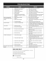
Enginefails to start
1.
2.
Chokecontrolnot in CHOKEposition.
Sparkplugwire disconnected.
1.
2.
Movechokecontrolto CHOKEposition.
Connectwireto sparkplug.
3.
4.
5.
Faultysparkplug.
Fueltank emptyor stalefuel.
Enginenot primed.
3.
4.
5.
Clean,adjustgap,or replace.
Filltank with clean,freshgasoline.
Primeengineas instructedin the OperationSection.
6.
7.
Keynot inserted.
Extensioncordnot connected(when
usingelectricstartbutton,on modelsso
equipped).
6.
7.
Insertkeyfully intothe switch.
Connectone end of the extensioncordto the electric
starteroutletand the otherend to a three-prong
120-volt,grounded,ACoutlet.
Enginerunningerratically/
inconsistentRPM(huntingor
1.
2.
Enginerunningon CHOKE.
Stalefuel.
1.
Movechokecontrolto RUNposition.
surging)
3.
Wateror dirt in fuel system.
2.
3.
Filltank with clean,freshgasoline.
Drainfueltank by runningengineuntil it stops. Refill
with freshfuel.
4.
Over-governedengine.
4.
ContactyourSearsParts & RepairCenter.
Excessivevibration
1.
Loosepartsor damagedauger.
1.
Stopengineimmediatelyand disconnectsparkplug
wire.Tightenall boltsand nuts.If vibrationcontinues,
haveunit servicedbya SearsParts& RepairCenter.
Lossof power
1.
2.
Sparkplugwire loose.
Gascap vent hole plugged.
1.
2.
Connectand tightenspark plugwire.
Removeiceand snowfrom gascap. Be certainvent
hole is clear.
Unitfails to propel itself
1.
Drivecable in need of adjustment.
1.
Adjustdrivecontrolcable. Referto Serviceand
Maintenancesection.
2.
Drivebelt looseor damaged.
2.
Replacedrive belt. Referto Serviceand Maintenancesection.
3.
Wornfrictionwheel.
3.
Havefrictionwheelreplacedat a SearsParts &
RepairCenter.
1.
Chuteassemblyclogged.
1.
2.
Foreignobject lodgedin auger.
2.
Stopengineimmediatelyand disconnectsparkplug
wire.Cleanchute assemblyand insideof auger
housingwith clean-outtoolor a stick.
Stopengineimmediatelyand disconnectsparkplug
wire. Removeobjectfrom augerwith clean-outtool
or a stick.
3.
Augercablein needof adjustment.
3.
Adjustaugercontrolcable. Referto Assembly
section.
4.
Augerbelt looseordamaged.
4.
Replaceauger belt. Referto Serviceand Maintenancesection.
5.
Shearpin(s) sheared.
5.
Replacewith newshearpin(s).
Chuteassembledincorrectly.
1.
Disassemblechute controland reassembleas
directedin the Assemblysection.
Unitfails to dischargesnow
Chutefails to easily rotate 180 1.
degrees
NEED HORE HELP?
Yot,Fttfind. th_
answer
a!ld mo_e on ma_age_y_ifeocom
Find this and att your other product manua[s ontine.
Get answers from our team of home experts.
Get a personalized maintenance
Find information
p[an for your home.
and tools to he[p with home projects.
managemylife
b_e'_g_t_/_eyeu by Sea_s
27
_ for
free]
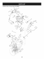
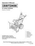
Craftsman Snow
Thrower
IViodel 247.883981
67 21
34
/ 30
52,.,
26
38
16
47
"15
56
\
59
/
21
21
\
11
lO
26
62
42
22
I
49
24
32
7O 25
\
61
69
70
73
44
\
24
23
28
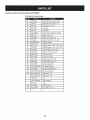
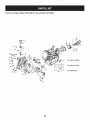
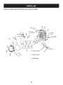
Craftsman
Snow Thrower
IViodel 247.883981
D =
2.
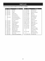
05244B
Housing,Bearing
784-0315A
Housing,Bearing
0
D =
W
O
736-0505
Washer,Flat,.34x 1.50x .150
39.
950-04020
Spacer,1.004x 1.375x .25
921-0146
Oil Seal
3.
918-04514
GearBoxAssembly,Auger
40.
4.
918-0281A
BracketAssy,Auger Brake
41.
936-3008
Washer,.344x .75x .12
5.
684-0090B-0637 Impellar,16"
42.
736-3046A
Washer,1.01x 1.86x .06
6.
684-04224-0691
Housing,Auger- 45"
43.
938-0281
Screw,Shoulder,.625x .17
7.
684-04151-4028
SpiralAssy,LH
44.
738-04155
Pin, Shear,.25x 1.75
8.
684-04152-4028
SpiralAssy,RH
45.
738-04159
Axle, Spiral,45"
9.
710-1245B
Screw,5/16-24x .875
46.
741-0192
Bearing,Flangew/Flats
10.
710-0389
Bolt, Carriage,3/8-16x .750
47.
941-04024
Bearing,SelfAligning
11.
710-0451
Screw,Carriage,5/16-18x .75
48.
941-0475
Bushing,Nylon
12.
710-0347
Screw,Hex Cap,3/8-16x 1.75
49.
741-0494
Bushing,Flange,1.051x 1.16
13.
710-0376
Screw,Hex Cap,5/16-18x 1.00
50.
747-0980A
Rod, AugerIdler
14.
710-04484
Screw,5/16-18x .750
51.
721-0325
Plug
52.
954-04194A
V Belt,4Lx 44.60"Long
15. J 926-04012
_Nut, Push
16.
736-0188
Washer,..76x 1.49x .06
53.
756-0178
Pulley,Flat Idler,2.75OD
17.
710-3168
Bolt, Carriage,3/8-16x 1.0
54.
756-04244A
Pulley,Auger Drive,10.0
18.
710-04606A
Screw,5/16-18x .4300
55.
784-0385C
Bracket,Auger Idler
19.
911-0677
Ferrule
56.
790-00264A-0637 Bracket,GearBox Support
20.
917-0299
Gear,Worm,DblThread
57.
921-0145
Seal,Oil
21.
712-04063
Nut,FlngeLk, 5/16-18
58.
936-0266
Washer,Flat,1.52ID x 2.00D
22.
712-04065
Nut,Fig Lk, 3/8-16
59.
790-00181
Drift Cutter
23.
941-0217
Sleeve
60.
790-00280-0637 Plate,Shave,45"
24.
936-0291
Washer,Flat,.88 ID x .38 OD
61.
741-0184
Bearing,Thrust
25.
914-0126
Key,Hi Pro,3/16 x 3/4
62.
784-5697-0637
Shoe,Skid
26.
914-0135
Key,Woodruff,I/4 x 3/4
63.
749-04384-0637 SupportTube
27.
714-04040
Pin,BowtieCotter
64.
710-3008
Screw,5/16-18x .75
28.
915-0118
Pin,Spirol,5/16 x 1.75
65.
748-04067A
Pulley,Adapter,.75Dia.
29.
725-0157
Tie, Cable
66.
918-0246
Hsg AssyAuger RH (Inc.40 & 70)
30.
731-1696B
Adapter,Chute,6"
67.
918-0247
Hsg AssyAuger LH(Inc.40 & 70)
31.
738-0275
Shaft,Gear,Worm
68.
710-1260A
Screw,LD, 5/16-18x .750
32.
731-05163
Spacer,1.0x 1.5x 1
69.
711-04714
Shaft, Drive,Auger
33.
731-2635
Clip, Mounting
70.
741-0670
FlangeBearing
34.
931-2643
Tool, Cleanout
71.
716-0111
Ext, Ret, Ring
35.
732-0858
Spring,Extension
72.
917-1425
Gear,Worm,LH
36.
936-0159
Washer,.349x .879x .063
73.
937-3000
Lube Fitting,3/16#70
37.
736-0174
Washer,.625x .885x .015
29
Craftsman
Snow Thrower
Model 247.883981
64
sl
56
52
3O
21
15
79
79
31
_/33
13
43 /
32
//
,/
\
3O
|-
ot
684-04308A
ChuteCrankAssembly
2
684-04350
Joint BlockAssembly
3
710-0276
4
710-04682
5
710-0572
6
|-
o_
731-0903E
LowerChute
43
731-1313C
ChuteTilt CableGuide
Screw,Carriage,5/16-18x 1.0
44
936-0231
Fiat Washer
Screw,Hex,3/8-16x 2.00 Lock,Gr5
45
784-5594-0637
CableBracket
Screw,Carriage,5/16-18x 2.5
46
631-04133A
HandleClutchLock- LH
710-3118
Screw,Hex,3/8-16x 1.0Lock,Gr5
47
631-04134B
HandleClutchLock- RH
7
712-04063
FlangeLock Nut,5/16-18
48
931-04187A
HandlePanel
8
912-3010
Hex Nut,5/16-18
49
646-0012
CableAssembly,Auger/Drive
9
914-0101
internalCotterPin
746-0952
Cable,Clutch
914-04040
_ internalCotterPin
10
_ 732-0184
Spring,Extension
11
715-04095
Spring Pin
50
684-04111B
HandleEngageAssy- LH
12
720-0201A
Knob,Crank
51
684-04112B
HandleEngageAssy- RH
13
720-04072A
Knob,WingNut,5/16-18
52
684-04250
RodAss'y,ClutchLock Pivot
14
926-0100
Cap, Push,3/8
53
710-04326
Screw,#8-16x 0.50
15
735-0234
Grommet,Rubber
54
710-04586
Screw,1/4-20x 1.625
16
736-0105
Washer,Bel,.375x .87x .063
55
710-0837
AB Screw,#10-16
17
936-0159
Washer,Fiat,.349x .879.063
56
710-1233
Screw,#10-24x 0.375
18
936-0185
Washer,.375x .738x .063
57
710-3069
Screw,1/4-20x.375
19
736-0242
Washer,Belleville,.34x .872x .06
58
712-04081A
ShoulderNut,1/4-20
20
941-0475
PlasticBushing,.380I.D.
59
720-04039
Shift Knob
21
747-04747
Eye Bolt
60
736-0159
Fiat Washer,.349x .879x .063
22
747-04925A-0637 Chute Rod
61
725-05148
WiringHarness(Not Shown)
23
749-04309-0691
Handle,Upper- LH
62
725-04393
Htd. HandGrip on/off Switch
24
749-04310-0691
Handle,Upper- RH
63
925-0659
LightSocket
25
749-0991-0691
Handle,Lower
64
725-05149
HeatedHandGrip
26
790-00329-0637
ChuteCrank Bracket
65
731-04894D
Lock Plate
27
716-04036
Ring, Retainer
66
731-04896B
ClutchLockCam
28
725-0157
CableTie
67
732-0193
CompressionSpring
29
731-06113
Trigger
68
732-04219C
ClutchLockSpring
30
738-04126
Pin, 3/16
69
732-04238
TorsionSpring
31
710-04022
Hex HeadScrew,MB 1.25
70
935-0199A
RubberBumper
32
732-04677
CableGuide
71
936-0267
Fiat Washer,.385x .87x .06
33
936-0264
Fiat Washer,.330x .630x .0635
72
738-04125
ShoulderScrew
34
984-04230
2-WayChuteControlTM Assy
73
738-04348
ShoulderScrew,1/4-20x 1.345
35
710-04187
Hi-Lo Screw,1/4-15x 0.5
74
746-04341
SpeedSelectorCable
36
710-0458
Bolt, Carriage,5/16-18x 1.75
75
790-00248B-0637 PanelBracket
790-00281B-0637 Shift Lever
37
710-0597
Screw,1/4-20x 1.00
76
38
710-0895
Hi-Lo Screw,1/4-15x .75
77
731-05324
LensPanel
39
712-04064
FlangeLock Nut, 1/4-20
78
777X41804
ReflectorLabel
40
731-0846C
UpperChute
79
746-04338
Cable,ChuteTilt
41
731-0851A
Chute,FlangeKeeper
80
710-0599
Self-TapScrew (Not Shown)
31
Craftsman
Snow Thrower
IViodel 247.883981
100
8Q
77
81
_101
78
53
15
35
7O
/7
55
37
/
26
11
/24
27
31
31
51
1/
12
71
32
Craftsman
Snow Thrower
IViodel 247.883981
D =
05244B
O
936-0300
Washer,.406x .875x .059
Dogg, SteeringDrive,LH
41.
936-0329
Washer,Lock, 1/4
618-0280P
Dogg, SteeringDrive,RH
42.
711-04615
Pin,Clevis
4.
918-0282E
Shaft Assembly,Steering
43.
914-0149B
Pin,InternalCotter
5.
918-04178
Assembly,FrictionWheel
44.
937-3000
Fitting,Lube,3/16 Drive
718-04034
Wheel,Friction,Bonded
45.
738-0143
Screw,Shldr.,.498x .34
710-0896
Screw,Hex Wash
46.
738-0279
Spindle,DrivePlate
618-0279P
3.
,
Housing,Bearing
O
6.
684-0118B-0637
Bracket,Auger Actuator
47.
738-0924A
Screw,Hex Shldr.,1/4-28
7.
684-0119B-0637
Bracket,DriveActuator
48.
741-0163A
Ass'y, Bearing/Housing
8.
684-0161-0637
Arm, Shift
49.
941-04025
Bearing,SelfAligning
9.
984-04103
RodAssembly,Shift
50.
741-04108
Bearing,Hex Flange
10.
684-04212-0637
Bracket,FrictionDriveSupport
51.
941-0563
Bearing,Ball
11.
684-04235
Sprocket,32T
52.
741-0747
Bush,Fig, .5625ID x 1.375x .4375
12.
710-04484
J TT Screw,5/16-18x .750
53.
741-0748
Bush,Fig, .5 ID x .627OD
13.
710-0538
Screw,Hex Cap Lock,
54.
746-04337A
Cable,Steering
14.
710-0599
Screw,Hex, 1/4-20x .50
55.
946-0951A
Cable,Auger Idler
15.
710-0788
Screw,Hex, 1/4-20x 1.00
56.
747-0973
Rod, DriveClutch
16.
710-1652
Screw,Hex Wash.
57.
750-04703
Spacer,1.01x 1.50x .93
17.
710-3001
Screw,Hex Cap,3/8-16
58.
750-04717
Spacer,.49x 7.865
18.
911-04279
Shaft, HexDrive
59.
750-04718
Spacer,.49x 3.545
19.
711-04605
Shaft,Actuator
60.
750-05342
Spacer,.566x .87x .190
20.
912-0116
Nut, Hex insertJam Lock
61.
750-05343
Spacer,.566x .87x 1.25
21.
912-0138
Nut, Hex,1/4-28GR5
62.
750-0903B
Spcr.,.514x .632x 2.44
22.
712-04065
Nut, Hx Flngeinsert Lk
63.
950-0997
Spacer,.675x 1.0x .23
23.
912-0413
Nut, Hx insert Jam Lk
64.
750-1302B
Spcr,.6725x 1.125x 2.48
24.
712-0717
Nut, insert3/8-16
65.
756-0344
Pulley,Drive
25.
713-0284
Chain,Endless,#41 x 36L
66.
756-0625
Roller,Cable
26.
713-0286
Chain,#420 x 40L
67.
784-0404
RetainerBracket
27.
913-04015
Sprocket,#41 x lOT
68.
784-0406A-0637
Bracket,FrameSupport
28.
914-0104
Pin, InternalCotter
69.
784-0407-0637
Bracket,Axle Support
29.
914-0135
Key,Woodruff
70.
790-00257-0691
Cover,UpperFrame
30.
914-0388
Key,Hi-Pro,3/16x 5/8
71.
790-00259-0691
Cover,LowerFrame
72.
790-00349-0691
Trans Frame
73.
684-04169
IdlerPulleyAssembly
Screw,Hex5/16-24x .75
31.
916-0104
32.
716-0136
•E-Ring
Ring, Retaining
33.
716-04048
Ring, Retainer
74.
710-0157
34.
917-0302
Plate,Drive
75.
710-0191
Screw,Hex3/8-24 x 1.25
35.
726-0221
Speed Nut,.500
76.
710-0607
Screw,Hx WashHd Tapp
36. _9320121
Spring,Extension
77.
710-0624
Screw,Hex Cap,5/16-24x 1.50
37.
932-0209
Spring,Extension
78.
710-0654A
Screw,3/8-16x 1.00
38.
936-0158
Washer,Lock,5/8
79.
710-0809
Screw,1/4-20x 1.25
39.
736-0242
Washer,Bell.,.34 x .872x .06
Continuedon followingpage
33
Craftsman
Snow Thrower
IViodel 247.883981
Continuedfrom previouspage
D =
0
e
738-04439
Screw,Hex Cap,5/16-24x .875
81.
710-0347
Screw,Hex Cap,3/8-16x 1.75
82.
714-0118
Key,Square,1/4x 1.5
83.
926-04012
Nut, Push
84.
931-2531
Cover,Belt
85.
732-04308A
TorsionSpring,.850dia. x .333Ig.
86.
936-0119
Washer,Lock,5/16
8_
736-3082A
Washer,Fiat,.406x 1.25
88.
736-3092
Washer,Fiat,.265x 1.0x .030
89.
952Z490-SUA
EngineComplete
90.
748-04112A
ShoulderSpacer,.3175x .500x .094
91.
750-04571
ShoulderSpacer,.260x .785x .538
92.
750-04821
ShoulderSpacer,.340x 1.00
93.
750-05316
Spacer,1.02x 1.63x .1425
94.
954-04194A
V-Belt,4L x 44.60
95.
954-04202
V Belt, 3/8 x 36.68
96.
756-04224
Pulley,Fiat idler,2.75 OD
97.
756-0241B
DoublePulley,3.25x 2.75
98.
784-0385D
Bracket,Auger idler
99.
790-00167A-0637 Belt KeeperBracket
100.
790-00208C
101.
790-00254A-0637 Belt CoverBracket
102.
634-0225A-0911
WheelAss'y.- LH
634-0226A-0911
WheelAss'y.- RH
734-2031
idler DriveWheelBracket
Tire
734-1124A-0662
RimAssembly
934-0255
Valve
103.
711-04606A
Axle, Wheel,45"
104.
756-04244A
Auger Pulley,10.0x .5
34
Craftsman
Snow Thrower
IViodel 247.883981
777D18046
777122341
777S32636
l.
EEP AWAY FROM ROTATING IMPELLER AND AUGER. CONTACT
WITH IMPELLER OR AUGER CAN AMPUTATE HANDS AND FEET.
2. USE CLEAN-OUT TOOL TO UNCLOG DISCHARGE CHUTE.
3. DISENGAGECLUTCH LEVERS,STOP ENGINE, AND REMAINBEHIND
HANDLES UNTIL ALL MOVING PARTS HAVE STOPPED BEFORE
UNCLOGGING OR SERVICING MACHINE.
4. TO AVOID THROWN OBJECTS INJURIES, NEVERDIRECT
DISCHARGEAT BYSTANDERS.USE EXTRA CAUTIONWHEN
OPERATINGON GRAVEL SURFACES.
777D16353
5. READ OPERATOR'S MANUAL.
CLEAN-OUT TOOL
_
=4
777S32280
777D16340
777123013
777122340
777D18038
35
777122363
Craftsman
Engine
Model
490=SUB
For Snow Model
247.883981
m
D =
I!
II
1
710-04915
Bolt M6x12
2
951-11339
MufflerShield
3
710-04915
Bolt M6x12
4
951-10757
ThrottleControlKnob
5
951-11595
ControlPanel
7
731-05632
Key
8
951-10637
KeySwitchAssembly
9
951-11302
ChokeKnob
10
710-04914
Bolt M6xlO
11
951-11181
ExhaustPipe Shield
12
951-11321
CarburetorHeatShield
13
710-04968
Bolt M6x16
14
951-11338
MufflerAssembly
15
712-05015
Nut, M8
38
951-11311
ThrottleControlAssembly
39
710-04915
Bolt M6x12
36
Craftsman
Engine
IViodel 490-SUB
For Snow IViodel 247.883981
130
_131
33
--134
137138_0_
147- CarburetorRebuildKit
139_
138
0--139
V
X
Y
m
D =
129
710-05392
StudM6-8x100
130
710-05056
StudM6-8x118
131
951-11315
132
m
O
D =
O
e
g
n/a
ThrottleShaft Cover
h
n/a
IdleJet Rivet
CarburetorIntakeGasket
h
n/a
IdleJet Assembly
951-11353
CarburetorInsulator
I
n/a
IdleSpeedAdjustingScrew
133
951-11354
CarburetorGasket
PrimerPipe
134
751-14035
CarburetorAssembly
J
k
n/a
751-11991
PrimerHose
135
951-10639A
PrimerAssembly
I
951-11906
PrimerHoseClamp
135
951-11824
PrimerBulb
m
n/a
CarburetorBody
136
951-11304
HeaterBox
n
n/a
FloatPin
137
951-11192
ChokeAssembly
o
n/a
EmulsionTube
138
736-04477
LockWasher
P
n/a
NickelPlatedBrassNeedleValve
139
712-05015
Nut M6
q
n/a
MainJet
147
751-14231
CarburetorRebuildKit
r
n/a
NeedleValveSpring
(Incl.h,l,n,o,p,q,r,s,t,v,x)
s
n/a
Float
a
n/a
ChokeShaft
t
951-11970
FuelBowlGasket
b
736-04638
ChokeControlLeverWasher
U
n/a
FuelBowl
C
710-05469
FuelShutoffLeverScrew
V
951-11348
FuelBowlGasket
d
n/a
ChokePlate
W
710-04945
FuelBowlMountingBolt
e
n/a
ThrottleShaft
X
951-11349
FuelDrainPlugGasket
f
n/a
ThrottlePlate
Y
710-04938
FuelDrainPlug
n/a
Gasket
37
Craftsman Engine IViodel
490=SUB
For Snow IViodel 247.883981
4O
I
42
44
43
42
61
141
140
144- GasketKit-Complete
145-GasketKit-External
146-CompleteEngine
49
38
Craftsman
Engine
IViodel 490=SUB
m
For Snow IViodel 247.883981
m =
O
m
Q
D =
W
O
4O
951-11951
ConnectingRodAssembly
68
710-06063
Bolt M8x35
41
951-12092
Piston
69
710-04968
Bolt M6x16
42
951-11953
PistonPin Snap Ring
7O
951-11320
Oil TubeSupportBracket
43
951-11954
PistonPin
71
710-05349
Bolt M6x8
44
951-12593
PistonRingSet
73
951-11381
Oil FillTubeO-Ring
48
951-11956
GovernorGear/ShaftAssembly
74
951-12073
Oil FillTubeAssembly
49
951-11373
RadialBall Bearing
75
951-11904
DipstickO-Ring
5O
736-04453
Flat Washer
76
951-11971A
DipstickAssembly
51
714-04077
GovernorShaftClip
77
951-11359A
CrankcaseKit
52
951-11958
GovernorSeal
53
951-11365
GovernorArm Shaft
54
951-11358
CrankshaftKit
(Inc.40-44,48-68,77-81,
(Inc.49,54,55,65,81)
102,105,106,108,110,111,
55
951-10307
WoodruffKey
56
715-04102
DowelPin 9 X 12
78
951-11350
Oil DrainPipe
57
715-04092
DowelPin 7 X 14
79
736-04440
DrainPipeWasher 10X16X1.5
58
951-11959
CamshaftAssembly
8O
710-04906
Oil DrainPlug Bolt
59
951-11376
CrankcaseCoverGasket
81
951-11499
Oil Seal
60
736-04545
Washer
140
951-12095
BalanceGearAssembly
61
951-11283
Oil FillPlug Assembly
141
951-11969
Bearing
62
951-11577
O-Ring
143
951-10641
Oil DrainAsm
64
951-14220
CrankcaseCover
144
951-11362
GasketKit- Complete
951-11340
CrankcaseCoverKit
(Inc.52,59,65,79,81,106,
(Inc.49,59,60,64-68)
108,125,131-133)
65
951-11375
Oil Seal
66
710-06061
Bolt M8x38
67
710-06062
Bolt M8x45
(Inc.49,52,77,81)
951-11360A
ShortBlockAssembly
125,131,132,140,141)
145
951-11363
GasketKit- External
(Inc.79,108,125,131-133)
146
39
952Z490-SUB
CompleteEngine
Craftsman
Engine
Model
490=SUB
For Snow Model
247.883981
142
123
123
123
_126b
(_
,126a
14S- GasketKit- [xternal
123
146- Complete[ngine
4O
Craftsman
Engine
IViodel 490-SUB
m
For Snow IViodel 247.883981
D =
O
m
0
D =
O
O
1CO 951-11337
ValveKit
116
951-12081
ExhaustLashCap
101
951-11337
ValveKit
117
951-11965
PushRodGuide
102
951-11962
Tappet
118
951-11981
RockerArmAssembly
103
951-11335
PushRodKit
119
710-04962
Bolt, Pivot
104
951-12592
CylinderHeadKit
120
951-11966
RockerArm
(Inc.106,110-112,125)
121
751-11123
AdjustingNut ,Valve
CylinderHeadAssembly
122
751-11124
PivotLockingNut
(Inc.100,101,104,106,108-112,
123
710-05054
ValveCoverBolt
114-122,125,129
-133)
124
951-11220
ValveCover
951-11967
ValveCoverGasket
951-11361A
105
715-04097
DowelPin
125
106
951-12094
CylinderHeadGasket
126a 731-07059
BreatherHose
SparkPlug/F6Rtc
126b 726-04101
BreatherHoseClamp
MufflerGasket
127
951-11317
CylinderBaffle
710-04915
BoltM6x12
107
108
951-10292
951-11212
109
710-04964
ExhaustStudM8x48.5
128
109
951-11207
MufflerStudAssembly
142
951-11333
ValveCoverKit
110
710-06064
BoltM10x1.25x87
144
951-11362
GasketKit- Complete
111
710-06065
BoltM10x1.25x65
(Inc.52,59,65,79,81,106,
112
951-11964
IntakeValveSeal
108,125,131-133)
113
951-12077
IntakeValveSpringRetainer
114
951-12078
ValveSpring
115
951-12080
ExhaustValveSpring Retainer
145
951-11363
GasketKit- External
(Inc.79,108,125,131-133)
146
41
952Z490-SUB
CompleteEngine
Craftsman
Engine
82
IViodel 490=SUB
For Snow IViodel 247.883981
83
8s
/
8
/
89
98
m
D =
m
O
D =
O
45
710-04965
Screw M4X 55
89
951-11313
CoolingFan
46
951-11196
ElectricStarter
90
951-11314
StarterCup
47
710-04967
Bolt M8x55
91
712-04220
FlywheelNut, M14x1.5
82
951-11305
IgnitionCoilAssembly
92
710-04968
Bolt M6x16
83
710-05350
IgnitionCoil Bolt
93
710-04915
Bolt M6x12
84
951-12553
AlternatorAssembly
95
951-11211
BlowerHousing
85
710-04969
Bolt M6x30
96
951-14223
Recoil StarterAssembly
86
710-04966
Bolt M6x8
97
736-04455
Flat Washer
87
951-11186
AlternatorWireClamp Bracket
98
710-04974
Bolt M6xlO
88
951-12556
Flywheel
42
Craftsman
Engine
IViodel 490=SUB
For Snow IViodel 247.883981
(_17
18
"_
27
I
26
34 32
24
m
D =
16
951-12533
17
951-11933
18
m
O
m =
O
O
FuelCap Assembly
27
951-11336
FuelLine Kit
FuelLevelIndicator
28
951-11700
FuelHose Clamp
710-04970
BoltM8x20
29
710-04921
Bolt M8x14
19
750-05312
Bushing,Slot
30
951-11182
FuelTankMountingBracket
2O
750-05313
Bushing,Rnd
32
712-04212
FlangeNut M6
21
951-11201
FuelTankAssembly
33
710-04908
GovernorArm Bolt M6X21
22
951-11319
FuelTankShroud
34
951-11307
GovernorArm
23
951-11318
FuelTankMountingBracket
35
951-11306
GovernorSpring
24
951-11351
EngineShroud
36
951-11203
ThrottleReturnSpring
25
710-04968
BoltM6x16
37
951-11309
GovernorRod
26
736-04452
Bush
43
FEDERAL
and/or CALIFORNIA
EMISSIONCONTROL
WARRANTYSTATEMENT
YOURWARRANTYRIGHTSANDOBLIGATIONS
MTD Consumer Group Inc, the United States Environmental
Protection Agency (EPA), and for those products
California, the California Air Resources Board (CARB) are pleased to explain the emission (evaporative and/or
warranty
on your 2013 and later small off-road
spark-ignited
engine and equipment
(outdoor
equipment
engines
must be designed,
built and equipped
to meet the State's stringent
equipment
engines
must be designed,
built, and equipped
to meet the U.S. EPA small off-road
equipment
anti-smog
certified
exhaust)
engine).
standards
engine
diagnosis,
condition
exists, MTD Consumer
Group Inc will repair your outdoor
equipment
new outdoor
regulations).
of time listed below, provided
Your ECS may include parts such as the carburetor, fuel-injection
system, ignition system, catalytic converter,
valves, canisters, filters, vapor hoses, clamps, connectors,
and other associated emission-related
components.
Where a warrantable
In California,
(in other states, outdoor
spark ignition
Consumer Group Inc must warra nt the ECSon your outdoor equipment
engine for the period
abuse, neglect, or improper maintenance
of the outdoor equipment
engine.
for sale in the state of
control system (ECS)
MTD
there has been no
fuel tanks, fuel lines, fuel caps,
engine at no cost to you including
parts, and labor.
MANUFACTURER'S
WARRANTYCOVERAGE:
This emission
control system is warranted
for two years. If any emission-related
part on your outdoor
part will be repaired or replaced by MTD Consumer Group Inc. In the event that a component
Manufacturer's
equipment warranty, the longer coverage period will apply.
equipment
is covered
engine
for longer
is defective,
the
than two years by the
/
OWNERSWARRANTY
RESPONSIBILITIES:
As the outdoor equipment
engine
Consumer Group Inc recommends
Group Inc cannot deny warranty
As the outdoor
your outdoor
equipment
equipment
owner, you are responsible
that you retain all receipts
for performance
of the required maintenance
listed in your owner's manual. MTD
covering maintenance
on your outdoor equipment
engine, but MTD Consumer
solely for the lack of receipts.
engine
owner, you should
however
be aware that MTD Consumer
engine or a part has failed due to abuse, neglect,
improper
Group Inc may deny you warranty
maintenance,
or unapproved
coverage
if
modifications.
You are responsible for presenting your outdoor equipment
engine to MTD Consumer Group Inc's distribution
center or service center as soon
as the problem exists. The warranty repairs should be completed
in a reasonable amount of time, not to exceed 30 days. If you have a question
regarding
http://su
your warranty
pport.mtd
coverage,
you should contact
the MTD Consumer
Group Inc Service Department
at 1-800-800-7310
or at
prod ucts.com.
GENERALEMISSIONS
WARRANTYCOVERAGE:
MTD Consumer
designed,
Group Inc warrants
built, and equipped
cause the failure of a warranted
The warranty
period
Subject to certain
1.
to the ultimate
so as to conform
part for a period
Any warranted
and exclusions
regulations;
equipment
Group Inc according
remainder
of the period.
for replacement
to subsection
as required
Any warranted
part that is scheduled
stated above. Any such part repaired
only for regular inspection
or replaced under warranty
3.
Any warranted
for replacement
part that is scheduled
replacement
as required
to an ultimate
maintenance
(4) below. Any such part repaired
2.
of time before the first scheduled
that the outdoor
on emission-related
stated above. If the part fails during the period of warranty
Consumer
period
purchaser
and (2) free from defects
engine is delivered
as stated below, the warranty
part that is not scheduled
period
and each subsequent
equipment
in materials
engine
is: (1)
and workmanship
purchaser
or first placed into service.
parts is as follows:
in the written
coverage,
instructions
supplied
the part will be repaired
or replaced
under warranty
is warranted
or replaced
will be warranted
for the
in the written instructions
supplied is warranted for the warranty
will be warranted for the remaining warranty period.
maintenance
in the written
instructions
supplied
date for that part. If the part fails before the first scheduled
Repair or replacement
to the owner.
5.
Notwithstanding
of any warranted
the provisions
service the subject engines
6.
The outdoor
equipment
emission-related
7.
MTD Consumer
warranty
8.
Throughout
warranted
9.
herein, warranty
part, provided
the off-road
herein must be performed
services or repairs will be provided
for diagnostic
that such diagnostic
Group Inc is liable for damages
parts sufficient
provisions
is warranted
replacement,
at a warranty
at all of our distribution
period
station
for the
the part
under
at no charge
centers that are franchised
or equipment.
engine owner will not be charged
warranted
of any warranted
Any replacement
part under the warranty
for
by MTD
will be repaired or replaced by MTD Consumer Group Inc according to subsection (4) below. Any such part repaired or replaced
warranty will be warranted for the remainder of the period prior to the first scheduled replacement
point for the part.
4.
that
of two years.
begins on the date the outdoor
conditions
the warranty
purchaser
with all applicable
to other engine
labor that is directly
work is performed
or equipment
associated
at a warranty
components
with diagnosis
of a defective,
station.
proximately
caused by a failure under
part.
engine
and equipment
warranty
to meet the expected
demand
part may be used in the performance
the owner. Such use will not reduce the warranty
period
stated above, MTD Consumer
Group Inc will maintain
a supply of
for such parts.
of any warranty
obligations
maintenance
of MTD Consumer
or repairs and must be provided
Group Inc.
without
charge to
to
10. Add-on
ormodified
partsthatarenotexempted
bytheAirResources
Board
maynotbeused.
Theuseofanynon-exempted
add-on
or
modified
partsbytheultimate
purchaser
willbegrounds
fordisallowing
awarranty
claims.
MTDConsumer
Group
Incwillnotbeliable
to
warrant
failures
ofwarranted
partscaused
bytheuseofanon-exempted
add-on
ormodified
part.
WARRANTED
PARTS:
The repair or replacement
of any warranted
part otherwise eligible for warranty coverage may be excluded from such warranty coverage if
MTD Consumer Group Inc demonstrates
that the outdoor equipment
engine has been abused, neglected, or improperly
maintained, and that
such abuse, neglect,
any adjustment
coverage.
Further, the coverage
The following
1.
or improper
of a component
emission
Fuel Metering
warranty
maintenance
was the direct cause of the need for repair or replacement
that has a factory
under this warranty
parts are covered
installed,
extends
and properly
operating,
adjustment
limiting
of the part. That notwithstanding,
device is still eligible
only to parts that were present on the off-road
for warranty
engine and equipment
purchased.
(if applicable):
System
Cold start enrichment
Carburetor
system (soft choke)
and internal
parts (or fuel injection
system)
Fuel pump
Fuel tank
2.
Air Induction
System
Air cleaner
Intake manifold
3.
Ignition
System
Spark plug(s)
Magneto
4.
ignition
system
Exhaust System
Catalytic
converter
SAI (Reed valve)
5.
Miscellaneous
Items Used in Above System
Vacuum, temperature,
Connectors
6.
Evaporative
position,
time sensitive valves and switches
and assemblies
Control
Fuel hose
Fuel hose clamps
Tethered
Carbon
fuel cap
canister
Vapor lines
050790 Rev.A
Look For Relevant Emissions Durability Period and
Air index information On Your Engine Emissions Label
Engines that are certified to meet the California Air Resources Board (CARB) Tier 2 Emission Standards must
display information regarding the Emissions Durability Period and the Air Index. Sears Brands Management
Corporation makes this information available to the consumer on our emission labels.
The Emissions Durability Period describes the number of hours of actual running time for which the engine is
certified to be emissions compliant, assuming proper maintenance in accordance with the Operating & Maintenance Instructions. The following categories are used:
Moderate:
Engine is certified
to be emission compliant
for 125 hours of actual engine running time.
Intermediate:
Engine is certified
to be emission compliant
for 250 hours of actual engine running time.
Extended:
Engine is certified
to be emission compliant
for 500 hours of actual engine running time.
For example, a typical walk-behind lawn mower is used 20 to 25 hours per year. Therefore, the Emissions
Durability Period of an engine with an intermediate rating would equate to 10 to 12 years.
The Air index is a calculated number describing the relative level of emissions for a specific engine family. The
lower the Air Index, the cleaner the engine. This information is displayed in graphical form on the emissions label.
After
July 1,2000, Look For Emissions
Compliance
On Engine Emissions
Compliance
Label
Period
After July 1, 2000 certain Sears Brands Management Corporation engines will be certified to meet the United
States Environmental Protection Agency (USEPA) Phase 2 emission standards. For Phase 2 certified engines, the
Emissions Compliance Period referred to on the Emissions Compliance label indicates the number of operating
hours for which the engine has been shown to meet Federal emission requirements.
For engines less than 225 cc displacement,
For engines of 225 cc or more, Category
Category
C = 125 hours, B = 250 hours and A = 500 hours.
C = 250 hours, B = 500 hours and A = 1000 hours.
This is a generic representation of the emission label typically found on a certified engine.
FAMILY YBSXS.3192VA
274812
GDOC-100182
Rev.B
46
Congratulations
on making a smart purchase.
Your new Craftsman®
product is designed and
manufactured
for years of dependable operation. But like all products, it may require repair
from time to time. That's when having a Repair Protection Agreement can save you money and
aggravation.
Here's
[]
[]
[]
[]
[]
what
the
Repair
Protection
Agreement*
includes:
Expert service by our 10,000 professional repair specialists
Unlimited
service and no charge for parts and labor on all covered repairs
Product replacement
up to $1500 if your covered product can't be fixed
Discount
of 25% from regular price of service and related installed parts not covered by the
agreement; also, 25% off regular price of preventive maintenance check
Fast help by phone - we call it Rapid Resolution - phone support from a Sears representative.
Think of us as a "talking owner's manual."
Once you purchase the Repair Protection
to schedule service. You can call anytime
Agreement, a simple phone call is all that it takes for you
day or night, or schedule a service appointment
online.
The Repair Protection Agreement is a risk-free purchase. If you cancel for any reason during the
product warranty period, we will provide a full refund. Or, a prorated refund anytime after the
product warranty period expires. Purchase your Repair Protection Agreement today!
Some limitations
and exclusions
call 1=800=827=6655.
*Coverage
6665.
in Canada
Sears Installation
apply.
varies on some
For prices and additional
items. For full details
information
call Sears Canada
in the U.S.A.
at 1=800=361=
Service
For Sears professional
installation
of home appliances, garage door openers,
other major home items, in the U.S.A. or Canada call 1=800=4=MY=HOME®.
47
water heaters,
and
Your Home
For troubleshooting,
product manuals and expert advice:
managernylife
www.managemylife.com
For repair - in your home - of all major brand appliances,
lawn and garden equipment, or heating and cooling systems,
no matter who made it, no matter who sold it!
For the replacement parts, accessories and
owner's manuals that you need to do-it-yourself.
For Sears professional installation of home appliances
and items like garage door openers and water heaters.
1-800-4-MY-HOME
®
(1-800-469-4663)
Call anytime, day or night (U.S.A. and Canada)
www.sears.com
www.sears.ca
Our Home
For repair of carry-in items like vacuums, lawn equipment,
and electronics, call anytime for the location of your nearest
Sears Parts & Repair Service Center
1-800-488-1222
(U.S.A.)
www.sears.com
To purchase a protection
1-800-827-6655
agreement
Para pedir servicio de reparaci6n
a domicilio, y para ordenar piezas:
(1-888-784-6427)
www.sears.com
®
(Canada)
www.sears.ca
(U.S.A.)
1-888-SU-HOGAR
1-800-469-4663
on a product serviced
by Sears:
1-800-361-6665
(Canada)
Au Canada pour service
en frangais:
1-800-LE-FOYER
Mc
(1-800-533-6937)
www.sears.ca
® Registered Trademark / TMTrademark of KCD IP, LLC in the United States, or Sears Brands, LLC in other countries
® Marca Registrada ! TMMarca de Fabrica de KCD IP, LLC en Estados Unidos, o Sears Brands, LLC in otros paises
MCMarque de commerce ! MDMarque deposee de Sears Brands, LLC