1
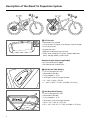
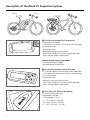
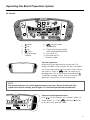
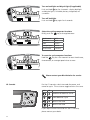
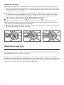
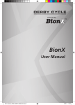
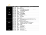
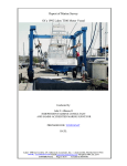
User Manual 2 Welcome Thank you for choosing BionX™. It is our goal to provide you with the highest quality electric propulsion systems available, and offer you the best possible after sales experience. This document serves as a supplement to your bicycle user manual. Please read this manual thoroughly, even if you are an experienced cyclist. Should you be unable to locate an answer in the manual, please contact your dealer for immediate assistance. We have always contended that a bike remain a bike. It is our love of cycling that drives us, and a passion that we continue to share with our customers. We hope you enjoy your new electric bicycle for many years to come. If you ever have concerns or questions that your dealer cannot provide answers to, or have comments relating to this user manual, feel free to contact us at [email protected] 3 User Precautions We want you to have a fun ride, but also a safe one. Carefully read the following information, even if you are an experienced rider. Take the opportunity to familiarize yourself with your BionX electric p ropulsion system before you take your first trip. 1.BionX recommends that you have your system installed professionally by an authorized dealer. 2.Read all of the enclosed installation and operating instructions from the manufacturer and follow the instructions, if any, prior to its first use. 3. Familiarize yourself with your electric bicycle and the functions of the BionX system in a safe environment before participating in road traffic for the first time. 4. Always wear a helmet when riding an electric bicycle for your own safety. 5. Make sure that the tires have the pressure recommended by the manufacturer before riding the bike. 6. Make sure that the brakes are operating properly before riding the bike. 7.Do not use a mobile phone or any other electronic devices while riding an electric bicycle; it is imperative that you pay attention to traffic. 8. If possible, ride in bike lanes and always in the correct direction of traffic. 9. Adhere to all valid traffic regulations. 10. Keep in mind that other traffic participants may underestimate the speed of an electric bicycle. 11. Ride with both hands on the handlebars when riding your electric bicycle. 12. Ride as defensively as possible. Enjoy your new BionX electric propulsion system! Your BionX Team 4 Table of Contents User Precautions 4 Description of the BionX SL Propulsion System 6 Description of the BionX PL Propulsion System 8 Inserting or Removing the Console 10 Inserting or Removing the Battery 11 Handling and Charging the Battery 12 Power supply 14 Chargers15 Assist Mode / Generate Mode 16 Operating the BionX Propulsion System 17 Operating the G2 throttle 19 Programming the Basic Settings 20 Removing and Installing the Rear Wheel 21 Maintenance and Care 22 Cleaning23 Transporting an Electric Bicycle on a Car 23 Repair and Spare Parts 23 Troubleshooting 24 Warranty Information and Guarantee 25 5 Description of the BionX SL Propulsion System 1 1 4 2b 2a 3 4 3 1 G2 Console • Removable G2 console • Illuminated LCD display with battery state of charge • 4 assistance levels • 4 generate levels • Backlight and bicycle light controls • Offers cycle computer functions (speed, odometer, clock, average speed, trip distance) Remote throttle (where applicable) • Assistance/Generate Toggle • Variable control throttle lever 2a 48V Down Tube Battery • Lithium Manganese (LiMn) • Removable, lockable • Fully charged in: 4-5h • Touch port state of charge indicator • XL – 48V / 8.8Ah / 423Wh • L – 48V / 6.6Ah / 317Wh (available in EU only) 2b 48V Rear Rack Battery • Lithium Manganese (LiMn) • Removable, lockable • Fully charged in: 4-5h • Touch port state of charge indicator • RR XL - 48 V / 8.8 Ah / 423 Wh • RR L - 48 V / 6.6 Ah / 317 Wh (available in EU only) 6 3 SL Motor • DC rear, high torque (HT) hub motor • Nom. 250W (EU), 350W (NA) • Nom. 9Nm / max. 40Nm (6.6/30lb-ft) • 1.2 Kg (2.6lb) lighter than the 250HT (EU) / 350HT (NA) motor • Brushless, gearless • Generate mode for energy recuperation • Integrated torque sensor 4 Brake switch • A surface mounted reed switch – connected to the BionX console and magnet • Upon activation assistance is shut off (“kill switch”) generate mode is activated Power Supply • Power supply to recharge the 48V LiMn battery • Input voltage: 100-240V • Output voltage: 26V • Max. charge current: 3.45A • Output: 90W 7 Description of the BionX PL Propulsion System 1 1 4 4 2b 2a 3 3 1 G2 Console (systems 2011 to present) • Removable G2 console • Illuminated LCD display with battery state of charge • 4 assistance levels • 4 generate levels • Backlight and bicycle light controls • Offers cycle computer functions (speed, odometer, clock, average speed, trip distance) 3 2 1 4 Remote throttle (where applicable) • Assistance/Generate Toggle • Variable control throttle lever 1 G1 Console (systems 2010 and earlier) • G1 console (optional throttle lever where applicable) • Illuminated LCD display with battery state of charge • 4 assistance levels • 4 generate levels • Backlight and bicycle light controls • Offers cycle computer functions (speed, odometer, clock, average speed, trip distance) 2a 22.2, 26 or 37V Down Tube Battery • Lithium Manganese (LiMn) • Removable, lockable • Fully charged in: 4-5h • L - 37 V / 9.6 Ah / 355 Wh • M - 26 V / 9.6 Ah / 250 Wh • S - 22.2 V / 6.4 Ah / 142 Wh 8 2b 37V Rear Rack Battery • Lithium Manganese (LiMn) • Removable, lockable • Fully charged in: 4-5h • RR L - 37V / 9.6Ah / 355 Wh • RR M - 37V / 6.4Ah / 236 Wh 50, 250HT (EU) / 350HT (NA), 3 2 or 500* watt Motor • DC rear hub motor • 250W : nom. 7Nm / max. 25Nm (5/18.5 lb-ft) • 250HT (EU) / 350HT (NA): nom. 9Nm / max. 40Nm (6.6/30 lb-ft) • 500W : nom. 9Nm / max. 25Nm (6.6/18 lb-ft) • Brushless, gearless • Generate mode for energy recuperation • Integrated torque sensor 4 Brake switch • A surface mounted reed switch – connected to the BionX console and magnet • Upon activation assistance is shut off (“kill switch”) generate mode is activated 37V Single Light Battery Charger (PL systems 2012 to present) • To recharge the 37V LiMn-battery • Input voltage: 100-240V • Output voltage: 37V • Max. charge current: 2A 22.2V, 26V or 37V Two Light Battery Charger (PL systems 2011 and earlier) • To recharge the 22.2V, 26V or 37V LiMn-battery • Input voltage: switchable between 115-230V • Output voltage: 22.2V, 26V or 37V depending on model • Max. charge current: 2A *Note: the 500 watt motor is not legal in all countries. Check with your local BionX dealer for local legislation and/or avaliability 9 Inserting or Removing the Console “click” Inserting the console • Slide the console into the console mount on the handlebar • Make sure that the console engages securely. When inserted correctly, you will hear a “click” Removing the console • Release the console by pushing the release lever on the console mount • Slide the console out of the console mount 10 Inserting or Removing the Battery Inserting the down tube battery 1 Place the battery into the docking station 2 Slide the battery down the rail gently towards the connector 3 The release arm will close automatically as the battery slides towards the connector 4 W ith the release arm almost closed, hold it in place and simultaneously press in the lock cylinder – you will hear a “click” when the lock cylinder is properly closed WARNING Do not force the battery arm closed, or force the battery onto the battery dock. This can bend the battery connector. 4 1 2 3 “click” )) ) m m) m4m mm 4m5..4 m 5. 225 .4 (2 ”” (((25 1” 111” 001 001 001 001 001 001 001 001 Removing the down tube battery 1 Turn off the BionX propulsion system (no illustration) 2 Lightly press on the battery release arm, insert the key and turn clockwise. The lock cylinder will protract, freeing the battery release arm 3 Remove the battery by opening the release arm 4 Slide the battery upwards on the rail 5 Lift the battery to remove 3 1” ) m m 4 5. (2 4 001 001 5 2 11 1” Inserting the rear rack battery: 1 Open the lock cylinder: please ensure that the key is removed from the lock cylinder 2 Place the battery onto the battery harness 3 Gently push the battery in a forward direction, towards the battery connector Make sure the battery is inserted all the way, flush with the battery connector 4 Push in the lock cylinder until a ‘click’ is heard (2 ) m 4m 5. WARNING 001 001 Do not force the battery onto the battery dock. This can bend the battery connector, or damage the rear light. 3 4 1 CLICK 2 001 001 001 001 Removing of the rear rack battery: 1 Turn off the system via the console (no illustration) 2 Turn the key in the lock cylinder until it pops out 3 Remove the key from the lock cylinder 4 Pull the battery backwards, along the battery rail 3 4 001 001 001 001 001 001 2 Handling and Charging the Battery WARNING BionX batteries shall only be recharged with BionX chargers or BionX power supplies. Never short circuit the battery by connecting the contacts of the battery. Never open the battery. This could damage the battery and possibly lead to overheating or ignition of the battery. The battery cannot be serviced by the user. Opening the battery case voids all warranty and product liability claims. Never use a battery which has obvious damage to the housing or the connector. 12 Make sure that the battery is no longer connected to the power supply or charger once the charging operation is complete. The Lithium Manganese battery cells have a low self-discharge rate, therefore a continuous connection of the battery to the power supply or charger is not necessary. We recommend that you fully charge the battery when it will not be used for a longer period of time, for example, before storing it for the winter, and then recharge the battery at minimum every three months. It is best to store the battery in a cool location at temperatures between 10 °C (50 °F) and 25 °C (77 °F). Never store the battery in locations where the temperatures can reach more than 45 °C (113° F) or fall below -10 °C (14 °F). The battery should never be exposed to extreme temperature fluctuations or humidity, and always protect the battery during storage from humidity to prevent corrosion on the connectors. Never drop the battery, and protect it from physical damage. Damage may lead to shortcircuits, and as a result cause overheating or ignition of the battery. Do not dispose of used batteries in regular household trash! Be aware that used batteries must be disposed of properly! BionX batteries can be returned to BionX to be recycled. Charging the battery: WARNING Only use the BionX power supply or charger that was supplied with the system to charge the battery. The use of other power supplies/chargers can damage the battery. The BionX power supply/charger should be used exclusively for rechargeable batteries of the specified type. The use of the BionX power supply/charger with batteries that are not rechargable may damage those and could lead to overheating, or ignition of the battery. Keep the power supply or charger away from water or moisture when charging and/or connected to prevent electrical shock or short-circuits. Do not use a power supply or charger that has obvious signs of damage to the cable, housing, or the connector. Extreme temperatures will affect battery life, especially during charging. Avoid charging in direct sunlight or in very hot or cold temperatures. This will reduce the life of the battery considerably. We recommend charging the battery at temperatures around 20 °C or 65 °F (room temperature). The battery should be warmed to room temperature before it is charged, particularly when it was exposed to cold temperatures during a ride. The battery can be charged when mounted on the bicycle or removed from the battery docking station. A Lithium Manganese battery does not have a memory effect, which means that the battery’s maximum energy capacity is not affected if it is repeatedly recharged after only being partially discharged. The battery does not need to be completely drained before charging. We recommend charging the battery after every ride, preferrably when the battery state of charge display shows less than 50%. We recommend that you fully charge the battery when it will not be used for a longer period of time, for example, before storing it for the winter, and then recharge the battery at minimum every three months. When the battery is depleted to the level where there is risk it could fall into deep discharge, the battery will signal that a recharge is needed by beeping. 13 Power supply SL system charging procedure (power supply) • Connect power supply and battery by inserting the charge connector into the touch port – the system can be turned on or off • Connect the plug of the power supply with the power outlet • The battery touch port (LED ring around the charging connector) lights up red upon inserting and then turns to amber during the charging process • When fully charged, the colour of the LED ring changes to green. The battery charging process is then complete • Following this procedure the charging connector should be disconnected from the battery • During the charging process you can check the battery state of charge through the console if the battery is connected to the system - a 48V system can be switched on while it is charging This has my vote :) Touch port red = upon inserting Touch port amber = charging Touch port green = fully charged The battery is fully charged after about 4 to 5 hours. Make sure that a completely charged battery is no longer connected to the charger after the charging procedure is completed. Battery state Colour 100-85 % Green 85-25 % Amber < 25 % Red Checking the 48V Battery State of Charge • Swipe your finger slowly over the touch port • Battery state of charge LED will illuminate • Allow ten (10) seconds before checking state of charge again NOTE The delivered power supply is suitable for the voltage ranges 110-115V or 220-230V. There is no need to manually set the voltage range for international use. 14 Chargers PL-250HT (EU) / PL-350HT (NA) systems charging procedure, 2012 - present (single light charger) • Connect the charger and battery by inserting the charge connector into the charge port. The system should be turned off • Connect the plug of the charger with the power outlet • The light on the charger will turn red automatically • The same light will then turn yellow to indicate charging, a fully depleted battery will take 4-5 hours to charge • The light will turn green, the battery is then fully charged and the charging process is complete • Following this procedure, the charger should be disconnected NOTE FU SE The 37V single light charger is suitable for the voltage ranges 110-115V or 220-230V. There is no need to manually set the voltage range, and there is no switch for this charger. 001 115 This notch is very important Left LED = red, charger on Right LED = yellow, charging Right LED = green, fully charged PL systems 22.2V, 26V, 37V charging procedure, 2011 and earlier (two LED charger) • Connect the charger and battery by inserting the charge connector into the charge port. The system should be turned off • Connect the plug of the charger with the power outlet • The power switch must be set to ‘on’ and the red LED will illuminate • The LED to the right of the red LED will illuminate yellow to indicate charging, a fully depleted battery will take 4-5 hours to charge • The right LED light will turn green, the battery is then fully charged and the charging process is complete • Following this procedure, the charger should be disconnected WARNING Check input voltage when travelling with charger, 001 or using any outlet adaptor. Failure to adjust the voltage switch on a two LED charger to the correct voltage range can result in damage to your charger. 115 This notch is very important 15 Assist Mode / Generate Mode The BionX propulsion system operates in four assist levels in the assistance mode, and in four charging levels in the generate mode. In the assistance mode, your pedaling is assisted proportionally by an electric motor that drives the rear wheel. A torque sensor is located on the axle of the electric motor and measures the effort provided by the rider; this produces natural feeling assistance from the motor. When in generate mode the electric motor functions as a generator and recharges the battery. When going downhill, you can regulate your speed by varying the generate level. This generate function provides a certain braking effect, however it does not replace legally required brakes. If the rear brake lever is pulled, the drive system automatically enters generate mode. The range can therefore be extended up to 15%, depending on the road conditions. 250HT (EU) / 350HT (NA) Motor performance Assistance Level (A) Degree of Assist Riding Situation 1 35% Riding on level ground 2 75% Slight inclines, head wind 3 150% Steep hills, strong head wind 4 300% Very steep roads Assistance Level (A) Degree of Assist Riding Situation 1 25% Riding on level ground 2 50% Slight inclines, head wind 3 100% Steep hills, strong head wind 4 200% Very steep roads 250/500 Motor performance Generation Level (G) 1 Slight downhill grade, tailwind 2 Significant downhill grade, tailwind 3 Steep descent 4 Very steep descent 16 Operating the BionX Propulsion System G2 Console 7 11 1 2 6 9 4 10 1. Power 2. Key 3. Key 4. Cycle 5.State of charge indicator 3 5 8 6. (bicycle) mode 7.Speedometer 8. Trip distance/average speed/ chronometer/odometer/clock 9. Assist level (A) 10.Generate level (G) 11.Wrench symbol Turn the system on Briefly push either top button on the console. The battery will beep 4 times and you will see a countdown, this is the system perfoming a self check. After startup, mode (no motor assist/ the system is always in bike operation). To turn the system off, briefly push . The battery will beep 5 times. After 5 minutes of “no operation” the system turns off automatically. NOTE The system performs a self check approximately every hour. Do not be alarmed if the system turns itself on briefly, and off again, or if the touch port flashes momentarily. Select assistance/generate level Push / key for more/less assist (see bar “fields 1-4” above display “A”). From mode push key to enter continuous generate mode. 17 Turn on backlight and bicycle light (if applicable) Push and hold key for 4 seconds - display backlight and bicycle light (if available, battery integrated) are turned on. 4s Turn off backlight Push and hold key again for 4 seconds. Select the cycling computer functions Briefly push the key to change between: 3 4 Trip Distance DIST Odometer ODO Clock CLOCK Average Speed AVSPD Chronometer CHRONO 2 1 To reset the cycle computer functions Hold the key for a few seconds to reset the distance, chronometer, or average speed values to zero. Please contact your BionX dealer for service. G1 Console For the G1 console, substitute mode for power, and crono for cycle. The assistance toggle remains the same. G1 G2 Mode/Power becomes Power Crono becomes Cycle Remains the same Remains the same If you require more information on the G1 console, please contact your dealer. 18 Operating the G2 throttle Throttle engagement: Default min. 3 kph to engage throttle Note: throttle control is variable, and the force gauge on the console reacts proportionally Assistance levels 1-4: From press for more assist or for less assist Generation 1-4: From press for more resistance or for less resistance NOTE The G2 throttle is only compatible with the G2 console, and may not be available in all countries. Check with your local BionX dealer for local legislation and/or availability. 19 Programming the Basic Settings In general, all basics settings for your BionX electric propulsion system are pre-set. Basic display functions can be set by entering the programming mode. Contact your dealer to customize the advanced functions of your system. Turn on the programming mode Simultaneously push and until the display shows “0000”. The first zero blinks. Change the value of the selection with or and confirm with . Select the other digits in the same manner until the desired program is displayed. Note: For G1 programming, substitute (mode) and respectively, plus and minus remain the same. (crono) for (power) and Code Description 2001 Select km/h or mph 2002 Regeneration/brake output (for reed switch) 0-40 (ideally 30-40) 2004 Clock adjust 2005 Tire circumference (millimeters) 2009 Flip Display Plus/Minus 0 = power left, 1 = power right (G2 only) (cycle) Code 2001 Code 2002 Code 2004 Select unit - km/h or mph. Select with or , and confirm with . Default value: 30. Change with and . Confirm with . Select hour/minutes with change value with and Confirm with . Code 2005 Code 2009 Set tire size (in mm) - Select digits one after another with or , and confirm with . Current setting of main functions is displayed. Flip = 0, assist toggle is on the right side of console; Flip = 1, assist toggle is on the left side of console. Confirm with . WARNING Do not use other programming codes without c onsulting your authorized dealer. If you type the wrong code, please push the key to exit programming mode. 20 , . Removing and Installing the Rear Wheel We recommend the removal and installation of the rear wheel to be done by a qualified dealer. Should you have to do this yourself, please follow the instructions below: WARNING Always turn off the propulsion system prior to plugging in or unplugging the motor cables. CAUTION It is essential that the axle nuts are tightened with a torque of 40Nm/30lb-ft; this assures that the propulsion system functions properly. Ensure the torque reaction collar is fully inserted into the dropout. The notch on the non-drive side must also be facing in the direction of 6 o’clock (within 5° either way). If this notch placement is incorrect, please consult your dealer. If your bike is equipped with hydraulic disc brakes: Do not pull the brake lever with the brake disc on the rear wheel removed from the caliper. Insertion of the wheel can be difficult or impossible as the brake pads will prevent brake disc from sliding in place. m 15m m 15m m 15m To Remove the rear wheel 1 Make sure that the system is turned off via the console (no illustration) 2 Remove the neoprene covers 3 Unplug the two cable 40Nm connections that lead to the motor 40Nm 40Nm (30lb-ft) (30lb-ft) 4 Disconnect the cable guide from the rear wheel brake (only on bicycles with rim brakes, not shown) 5 Loosen the axle nut on the rear wheel using a 15mm ring wrench 6 Slide the rear wheel downwards, out of the dropout 5 2 mm 15 15mm mm 15 3 6 21 Installing the rear wheel 1 Guide the rear wheel axle into the dropouts and make sure that the brake disc (on models with disc brakes) is inserted between the brake pads. Also make sure that the flat area at the left of the rear axle (torque reaction collar) is aligned so that it fits into the left dropout (no illustration). Make sure the axle is inserted all the way in the dropouts 2 T ighten the axle nuts on the rear wheel with 40Nm/30lb-ft (= VERY TIGHT!). This torque is essential for the correct function of the propulsion system. If you do not have a torque wrench, use a normal ring wrench. Have your dealer check the torque of the axle nuts as quickly as possible. Use only the original axle nuts; otherwise you run the risk of damaging the axle threads 3 Plug in the cable connections (POWER A before COMMUNICATION B ) 4 Keep the motor cables clear of the brake disc (on models with disc brakes) and the motor casing 5 Now replace the cable pull. Re-install the cable guide of the rear wheel brake (rim brakes only), and correctly adjust the rear wheel brake (no illustration) 6 Place the larger neoprene cover over the plug-in connections, and the smaller neoprene cover closer to the disc/motor to prevent the cables from wear 3 A 4 B m 15mm 15m m 15m 2 6 40Nm 40Nm (30lb-ft) (30lb-ft) Maintenance and Care 15 mm 15 15mm mm We recommend to have the spoke tension of the rear wheel and the torque of all screws checked by your qualified dealer after the first 200km (125 miles). In order to ensure extended use of the propulsion system, all plug-in contacts of the system should be checked every two to three months and cleaned with a soft and dry brush, if necessary. It must be ensured that no dirt or humidity penetrates the battery docking station when the battery is removed. The electric motor is a brushless DC-motor that does not have to be serviced. 22 Cleaning CAUTION Never use a high pressure washer or a garden hose to clean the propulsion system. The force of a water jet could damage the electrical components of the propulsion system. We recommend a soft sponge or a soft brush to clean the bicycle. Use a moist rag to clean the battery’s docking station. Always use very little water, and keep water away from the electrical contacts. Check the plug-in connections for moisture after cleaning and let these dry, if necessary, before reusing the bicycle. Transporting an Electric Bicycle on a Car WARNING Make absolutely sure that the bike rack on your car is suitable for the increased weight and the unique frame style of your electric bicycle. A rack that is not suitable can be 115 damaged or even break during the transport of the electric bicycle. The electric bicycle can be damaged by an unsuitable bike rack. For transportation of the electric bicycle on a bike rack always remove the battery and the console. In case of weather, your motor and system connections should be covered from the elements. Repair and Spare Parts For repair of your electric bicycle consult your qualified dealer. All of the original spare parts for your electric bicycle can be purchased through your dealer. If you need spare keys for the battery, please contact your dealer. Please retain the key number for your records. It is located on your battery key, as well as on the face of the battery lock cylinder. 001 BionX Key Number 23 Troubleshooting The system does not turn on Check the battery and make sure that it is charged. The battery must be correctly inserted in the docking station and the lock must be completely closed. Also check that all connectors of your wiring harness are properly engaged, and your console is inserted properly. If the problem persists, contact your authorized dealer. The system can be turned on but there is no assist Check that the cables running from the battery to the motor are properly connected. If the problem persists, contact your authorized dealer. The system is continuously in generate mode When the propulsion system is continuously in generate mode and cannot be switched back to assist mode by pushing the key, the problem most likely lies with the brake switch that are located at the brake lever. In this case try to “repair” the system by turning it off and then on again if that does not solve the problem, you can temporarily bypass it by removing the plug-in connection from the console to the brake switch. WARNING If you bypass the brake switches you also disable regenerative braking, in doing so your system will not provide any brake support. We recommend that you contact your dealer as soon as possible. The motor is not as powerful after a repair or service Tighten the nuts of the rear axle with the specified torque (40Nm/30lb-ft). If the problem persists, contact your authorized dealer. The battery state of charge display on the console does not show “full” after a complete charging procedure Make sure that you have followed all of the instructions for the charging procedure. Let the battery cool off for a few hours and then recharge it again. If the problem is still not solved, let the battery cool again, fully deplete the battery and charge it again. If the problem persists, contact your authorized dealer. 24 Warranty Information and Guarantee 1. The BionX warranty covers a two-year period for BionX propulsion system(s) within the framework of the following conditions. 2. This warranty exclusively covers systems provided by BionX excluding all the other bicycle components provided by other bicycle manufacturers. 3. This warranty covers the repair and/or the replacement of BionX propulsion systems provided that the equipment concerned loses its functionality within the agreed warranty period and also provided that the claim is not related to any of the following cases expressly excluded under this warranty. 4. Any other legal provisions, particularly with respect to warranty regulations, are not restricted by this warranty. 5. This warranty only covers material and manufacturing defects. It is only effective with a valid proof of purchase consisting of the original purchase document or receipt indicating the date of purchase, the dealer’s name and the designation of the system model. BionX reserves the right to reject the coverage of this warranty if the accompanying documentation of BionX components is not accurate or complete. 6. In the case of a warranty claim, BionX undertakes to either repair faulty system components and/or to replace such components, at BionX discretion (Service Replacement Unit). 7. Warranty repairs have to be exclusively performed by BionX. Any component to be repaired under the framework of this warranty has to be transferred to the dealer at the client’s own expenses and risks, and, after the completion of such repair, has to be picked up at the dealer. In the case of rightful warranty claims, BionX reserves the right to bear or repay transportation expenses. In order to have a previous determination whether a warranty claim is justified or not, the end user has to submit his claim to the dealer from whom he purchased the product so that the respective dealer handles the shipment to BionX. 8. Costs for repair work performed in advance by persons who have not been authorized by BionX will not be reimbursed. In such a case, any warranty claim will cease. 9. Repair work and/or replacement of components during the warranty period do not lead to an extension and/or a new start of the warranty period. Repair work and direct replacement during the warranty period may be performed with functional replacement components of equal value. 10.The two-year warranty period starts with the date of purchase. Warranty claims must be reported immediately. 25 11.No warranty claims are accepted - without limitation to other reasons - in the case of damages due to the following: a) External influences, particularly falling rocks, collision, accident and other external events with an immediate external effect due to mechanical powers. b) Purpose and/or malevolent acts, theft and robbery as well as natural hazard events and/or acts of mischief. c) Test, maintenance, repair and replacement work due to normal use. d) If the battery/cell pack does not provide full capacity in the course of normal use or for batteries going through a normal aging process or reduction of performance, BionX warranty only covers that within the two-year warranty period or after 600 charging cycles, whichever event occurs first, to the condition that the battery still provides at least 70% of its initial capacity. e) In the case of inappropriate use, e.g. the product was exposed to liquids, chemicals of any type and/or extreme temperatures, wetness and humidity and/or if the battery suffers damages due to non-compliance with the special instructions set forth in the chapter “Handling and Charging of the Battery“. f) The model, serial or product number on BionX product has been changed, deleted, blurred or removed. The seal (serial number sticker) on the battery housing has been broken or obviously manipulated. g) Use of the battery in systems that are not approved for such use with this particular product. h) Operation of the BionX system with batteries other than the batteries designed for the BionX system. i) Damages to the battery due to overcharging or not adhering to the instructions of battery handling (refer to user manual). 12.This warranty only covers the above mentioned repair work and/or the replacement of defective or compromised components. It excludes any claims as to the reimbursement of property damages, downtimes, expenses for renting or leasing equipment, travel expenses, lost profit or any other claims. BionX liability in connection with this warranty is limited to the respective acquisition value of the product. 26 BionX, BionX Design and powered by BionX are trademarks of BionX International Corporation. ©2011 BionX International Corporation. All Rights Reserved. 27 Your dealer bionxinternational.com