1
CYCLE COMPUTER OWNER'S MANUAL
˜
ENGLISH FRANÇAIS ESPANOL
DEUTSCH ITALIANO
INTRODUCTION
Congratulations on your purchase of the new Vetta C-16 cycle computer. Packed with all the features that a
professional rider needs to keep track his workouts, the new C-16 has been redesigned to dramatically
improve its reliability when used off-road. A new sealed case and heavy duty bracket combined with our
new universal sensor (pat. pend.) make the C-16 one of the most durable computers Vetta has ever produced.
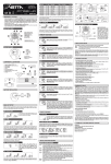
DRAWINGS OF PARTS
Head Unit
Sensor
Bracket
Battery
Magnet
Rubber Shims
LISTING OF FUNCTIONS
SPEEDOMETER (
)(
or
)
Tells you your instantaneous speed. Accurate to 0.5 mph or kmph.
AUTOMATIC RIDE TIME STOPWATCH (
)
Stopwatch activated by wheel movement, turning on when you ride and off when
you stop. Records true ride time, time spent actually riding, up to 9:59:59.
SPEED COMPARATOR ( or )
Compares current speed to average speed. As you are riding a ( ) or a ( ) will
appear in the upper right hand corner of the display. This will indicate whether
your current speed is faster ( ) or slower ( ) than your current average speed.
This function is automatic, requiring no programming and cannot be disabled.
TRIP ODOMETER (
)
Tells you the distance for your current ride from 0 to 999.9 mi. or km.
AVERAGE SPEED (
)
Your average speed calculated using your true ride time and trip distance.
CUMULATIVE ODOMETER (
)
Tells you your cumulative distance for the year from 0 to 99999 mi. or km.
MAXIMUM SPEED (
)
Displays the fastest speed that you have traveled.
DIGITAL 12 HOUR CLOCK
Gives you the time of day in a 12 hour format.
AUTO SHUT DOWN
As a battery saving device, Vetta computers will automatically shut down after
5-10 minutes of non-use. Your C-16 will automatically restart itself as soon as
the unit receives input from the wheel.
FREEZE FRAME MEMORY (FLASHING DISPLAY)
This feature allows you to store a snapshot of the display for an extended period
of time. This feature is useful at the end of a race, allowing you to hold a record
of your time, distance, average speed and maximum speed while you are cooling
down. While the display is frozen, the computer will continue to update and store
ride information. All information is updated and displayed as soon as the freeze
frame memory is turned off.
ACTIVATE FREEZE FRAME MEMORY
In any mode, press the left computer key (B) for approximately 1 second. The entire display will flash indicating
that the feature is active. You may now cycle through the functions by pressing the right hand key (A).
DEACTIVATE FREEZE FRAME MEMORY
Press the left computer key (B) to update the display and return to normal operation.
RESET CYCLING FUNCTIONS
In the
/
mode, press both keys for 2 seconds to clear the
,
,
and
displays.
!
WARNINGS AND CAUTIONS
!
CAUTION Vetta Sports encourages you to ride safely. Wear a helmet every time you ride, use a front
and rear light at night, and always keep your eyes on the road ahead of you.
!
CAUTION Vetta cycle computers are sophisticated electronic instruments. Vetta recommends that this
product be installed only by a qualified bicycle retailer. Failure to read these instructions and improper
installation of this device may void the warranty. If you are in doubt about any aspect of the installation or
operation of this product, consult your local bicycle retailer for clarification.
BATTERY INSTALLATION
CAUTION
AUTO CLEAR BUTTON
Press for total reset of unit.
All stored data will be erased.
!
The C-16 uses a common 186 1.5v button cell battery. Replacement batteries are
available at most camera shops and from your Vetta retailer. Under normal usage
a battery should last approximately one year. NOTE: Most problems that occur
with cycle computers are caused by dead or weak batteries. If you are having
problems with your computer's operation, check and replace the battery first.
STEP 1
Remove the battery cover from the bottom of the computer using a small flat
blade screwdriver.
STEP 2
Install the battery into the battery compartment with the positive (+) side of the
battery facing the compartment door. Be careful when you are installing the
battery not to bend any of the battery contacts.
186 1.5v Battery
STEP 3
Press the battery cap firmly into place making sure that the rubber o-ring seal does
not get pinched or distorted as this will compromise the waterproofing of the unit.
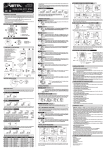
BUTTON FUNCTIONS
“A” BUTTON (RIGHT)
Controls progressing through functions and settings, and advances the screen
while programming the computer.
“B”
“A”
“B” BUTTON (LEFT)
Controls advancing through the digits while programming the computer and
activating the Freeze Frame memory function.
PROGRAMMING THE HEAD OF THE COMPUTER
Now that you are familiar with the features of your Vetta cycle computer, you are ready to begin programming
the unit specifically for your bike. Take a few minutes to familiarize yourself with the buttons and keystroke
sequences before you proceed to the programming of the unit.
SETTING MILES/HOUR OR KILOMETERS/HOUR
All Vetta cycle computers are capable of being programmed to read out in either
miles or kilometers. It is also possible to change back and forth between miles
and kilometers by simply reentering the setting program and changing your
choice of measurements.
STEP 1
With the computer in the
/
mode, press the right key (A) for over 2 seconds.
STEP 2
The screen will clear and the
icon will flash along with the Default Wheel
Size Setting of 2074mm (700 x 20c). Press the left key (B) to select either miles
(
) or kilometers (
).
STEP 3
Set your choice and advance to the wheel size setting mode by pressing the right
key (A) again.
DETERMINING YOUR PROPER WHEEL SIZE
Vetta cycle computers are programmed using the circumference of the wheel measured in millimeters. Note
that while your computer can be programmed to +/- 1mm for total accuracy, discrepancies of as much as
50mm or more will not have a significant effect on the accuracy of the unit for most normal rides.
The following chart lists the programming sizes for some of the most popular wheel sizes currently in use.
These numbers are estimations and may vary slightly from the size of your actual wheel depending on the
manufacturer of the tire that you are using.
TIRE SIZE
CIRC.
TIRE SIZE
CIRC.
TIRE SIZE
CIRC.
26 x 1.7
2035
27 x 1-1/4
2180
700 x 25c
2124
26 x 1.9
2055
650 x 20c
1945
700 x 28c
2140
26 x 2.0
2075
650 x 23c
1990
700 x 32c
2155
26 x 2.1
2095
700 x 20c
2074
700 x 38c
2170
27 x 1.0
2140
700 x 23c
2114
700c Tubular
2130
WHEEL SIZE CALCULATION
If the wheel size of your bike is not listed in the chart, follow these simple steps to calculate the calibration
number for your bike.
STEP 1
Measure the distance from the center of the front axle to the ground in millimeters. If you are measuring in
inches, multiply the number of inches by 25.4 to get millimeters. If you want total accuracy make this
measurement while you are sitting on the bike.
STEP 2
Multiply the above number by 6.2832 (2π).
STEP 3
Enter the resulting number into the computer.
PRESET VALUE
The C-16 has a factory preset wheel size value of 2074 (700 x 20c).
PROGRAMMING YOUR WHEEL SIZE
STEP 1
Once you select miles (
) or kilometers (
) and press the right key (A),
the C-16 will automatically advance into the wheel size setting mode. (See SETTING
MILES/HOUR OR KILOMETERS/HOUR)
STEP 2
The right hand digit (4) will begin flashing. Use the left key (B) to advance to the
number that you want. NOTE: Hold the left key (B) to fast advance through the digits.
STEP 3
Press the right key (A) to set the number and advance to the next flashing digit (7).
STEP 4
Repeat this sequence until all digits are at the appropriate settings.
STEP 5
Press the right key (A) one final time to enter the wheel size setting into memory
and advance the unit back to the
/
screen.
SETTING THE CLOCK
The Vetta C-16 cycle computer is equipped with a digital clock that displays time
in a 12 hour format.
STEP 1
With the display in the
mode, press the right key (A) for 2 seconds.
STEP 2
The screen will clear and the hour digits will begin to flash. Advance the digits
using the left key (B). NOTE: Hold this key to fast advance through the digits.
STEP 3
When you have selected the correct digit, press the right key (A) to enter the digit
and advance to set the minutes using the same procedure as above.
STEP 4
Press the right hand key (A) to set the minutes and return to the
screen.
MAGNET, SENSOR AND BRACKET INSTALLATION
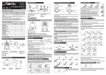
We recommend that you install your C-16 in the following manner, starting with
the sensor unit on the fork and working up to the mounting bracket on the handlebar.
Sensor
Zip-Tie
Alignment
Arrow
Wheel
Magnet
Fork Leg
1-2mm
STEP 1
Mount the new Vetta universal S-2 sensor (pat. pend.) loosely (so that you can
slide it around) to the fork blade using the zip-tie provided. The sensor can be
mounted at any point along the fork, however, we recommend a position on the
back side and near the top of the left fork blade. This will protect the sensor from
being hit by rocks, trees and other objects.
STEP 2
Again, loosely install the sensor magnet to one of the spokes on the left side of
the front wheel. Adjust the magnet and sensor position by sliding both pieces
around until you get the sensor as high on the fork blade as possible while still
maintaining the necessary magnet to sensor spacing (1-2mm). NOTE: The magnet
should pass within 1-2mm of the sensor, and the top of the magnet should be no
higher than the top of the small arrow molded into the face of the sensor.
STEP 3
Route the sensor wire up the back of the fork securing with electrical tape.
!
CAUTION Do not use zip-ties to secure the sensor wire to the bike as this
may result in cut or broken wires.
!
CAUTION Be sure to leave enough slack in the wire to allow for the steering
motion of the bike and the action of the suspension fork, if you have one.
STEP 4
Carefully wrap the excess sensor wire around the front brake cable housing,
securing with electrical tape when necessary. When you are finished, you
should have just enough slack for the computer mounting shoe to reach the
handlebar.
Check to make sure that all of the excess sensor wire is either taped down or
wrapped around the brake cable so that nothing can catch on it while you are riding.
Wiring Diagram
BRACKET INSTALLATION
Clamp the bracket around the handlebars and tighten in place. All Vetta cycle computer brackets are designed
to work with 26.0 - 26.4mm standard diameter road handlebars. Shims are provided to fit smaller 25.4mm
mountain and road bars. Make sure not to over tighten the bracket as this may result in breakage. The
bracket only needs to be tightened enough to keep it from spinning on the handlebar during normal riding.
HEAD UNIT INSTALLATION
The heads of all Vetta computers are designed to lock into their brackets. When
installing your computer head into the bracket you should hear an audible “SNAP”
indicating that the unit is locked firmly in place. The head of the C-16 will slide
into the bracket from the front to the back.
PAGE 15
TEST OF INSTALLATION
Once you have finished with the installation procedure, you are ready to test the unit to make sure that it works.
STEP 1
Advance the computer to the speedometer mode.
STEP 2
Pick up the front of the bicycle and spin the front wheel. The computer should register speed within 1-2 seconds.
If you do not get a speed reading, check to be sure that the magnet and sensor alignment is correct and that
the space between the magnet and sensor is 1-2mm or less. If this does not solve the problem, call the Vetta
customer service hotline at 1.800.GO.VETTA.
WARRANTY
Vetta Sports warrants all Vetta products, to the original purchaser, to be free of defects in materials or
workmanship for a period of one year from the original date of purchase. Vetta Sports will, at its sole
discretion, repair or replace any product deemed defective. This express warranty is in lieu of all other
warranties, either expressed or implied. Any warranties of merchantability of fitness for a particular purpose
are limited to the one year duration of the above express warranty. Vetta Sports will not be held liable for any
incidental or consequential damages.
WARRANTY RETURN AND REPAIR PROCEDURE
If you ever experience a problem with the function of your Vetta C-16 cycle computer, please visit your local
Authorized Vetta Dealer for assistance.
Should you experience a problem with your Vetta C-16 cycle computer that can not be solved by your local
Authorized Vetta Dealer, please ask them to comply with the following simple steps to assure quick and
efficient processing of your claim.
STEP 1
Fill out the warranty information card within this manual.
STEP 2
Call the appropriate Vetta Customer Service number listed below for help or to obtain a Return Authorization
Number (RA Number).
STEP 3
Send the unit back to the appropriate Vetta Customer Service Center along with the original copy of your
purchase receipt and a detailed explanation of the problem you are experiencing.
Vetta Customer Service USA
1500 Kearns Boulevard Suite A-200
Park City, UT 84060 USA
Phone: 1.800.GO.VETTA or 1.801.647.2929
Fax: 1.801.647.2947
Email: [email protected]
Serving: US, Canada, South America, Australia,
New Zealand, and Asia
Vetta Customer Service Europe
Via E. Fermi 4
Casella d'Asolo (TV) 31010 Italy
Phone: 39.423.524094
Fax: 39.423.524199
Email: [email protected]
Serving: Europe and the Middle East
WARRANTY INFORMATION CARD
Name
Address
Phone/Fax Number
RA Number
Place of Purchase
Problem
Date of Purchase