1
®
NU
917.257641
OWNER'S
MANUAL
TH
• Assembly
• Operation
° Customer Responsibilities
° Service and Adjustments
. Repair Parts
CAUTION:
Illllll'
Rc_.d and follow
IlllllllllllI llll Illlll
all safety
Convertible
rules and instructions
IH IllllIllll II
before operating
IIIH IlllllllllIllllllllIlllll
this equipment,
IlllII Illl
SAFETY
Practices RULES
for Ride-On
Safe Operation
Mowers
IMPORTANT: THIS CUTTING MACHINE tSCAPABLE OFAMPUTATING HANDS AND FEET AND THROWING OBJECTS.
FAILURE TO OBSERVE THE FOLLOWING SAFETY INSTRUCTIONS COULD RESULT IN SERIOUS INJURY OR DEATH.
I.
GENERAL
•
Read, understand, and follow atl instructionsin the" manual
and on the machine before starting
Only allow responsible adults, who are familiar with the
instructions, to operate the machine.
Clear the area of objects such as rocks, toys, wire, etc.,
which could be picked up and thrown by the blade
Be sure the area is clear of other people before mowing Stop
machine if anyone enters the area,
Never carry passengers
Do not mow in reverse unless absolutely necessary Always
look down and behind before arid while backing.
Be aware of the mower discharge direction and do not point
it at anyone Do not operate the mower without either the
entire grass catcher or the guard in place
Slow down before turning
Never leave a running machine unattended. Always turn off
blades, set parking brake, stop engine, and remove keys
before dismounting.
Turn off blades when not mowing
Stop engine before removing grass catcher or unclogging
chute
•
•
•
=
°
•
•
•
o
•
°
°
•
OPERATION
Ill.
=
°
Before and when backing, look behind and down for sma]l
children
°
Never carry children. They may fair off and be seriously
injured or interfere with safe machine operation..
Never allow children to operate the machine.
Use extra care when approaching blind comers, shrubs,
trees, or other objects that may obscure vision
IV. SERVICE
°
=
°
OPERATION
°
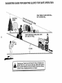
Slopes are a major factor related to Ioss-of-control and tipover
accidents, which can result in severe injury or death, All slopes
require extracaution, ifyoucannot backuptheslope orifyou feel
uneasy on it, do not mow iL
,,
DO:
•
•
°
•
•
•
Mow up and down slopes, not across,
Remove obstacles such as rocks, tree limbs, etc,
Watch for holes, ruts, or bumps. Uneven terrain could
overturn the machine. Ta!/ grass can hide obstac/es
•
Use slow speed Choose a low gear so that you will not have
to stop or shift while on the slope,
•
Follow the manufacturer's
recommendations
for wheel
weights or counterweights to improve stability
•
Use extra care with grass catchers or other attachments
These can change the stability of the machine
=
Keep all movement on the slopes slow and gradual Do not
make sudden changes in speed or direction.
°
Avoid starting or stopping on a slope. If tires lose traction,
disengage the blades and proceed slowly straight down the
slope
DO NOT:
o
.
•
•
•
Keep children outof the mowingarea and under the watchful
care of another responsible adult.
Be alert and turn machine off if children enter the area..
•
•
.
Mow only in daylight or good artificial light
Do not operate the machine while under the influence of
alcohol or drugs.
Watch for traffic when operating near or crossing roadways
Use extra care when loading or unloading the machine into
a trailer or truck.
11, SLOPE
CHILDREN
Tragic accidents can occur' if the operator is not alert to the
presence ofchildren. Children are often attracted to the machine
and the mowing activity. Neverassume that children will remain
where you last saw them_
•
°
Use extra care in han_,t Jygasoline and other fuels. Theyare
flammable and vapors are explosive..
Use only an approved container'
Never remove gas cap or add fuel with the engine
running. Allow engine to cool before refueling Do not
smoke.
Never refuel the machine indoors
Never store the machine or fuel container inside where
there is an open flame, such as a water heater.
Never run a machine inside a closed area.
Keep nuts and bolts, especially blade attachment bolts, tight
and keep equipment in good condition
Never tamper with safety devices. Check their proper
operation regularly
KeenmachiqefreAefgrass
I,_w:
orotherdebdsbuild-up_
Clean Oll ,Jr _Llel _pi;_,dg=, ,=JJu_vrrlaonln_ to coo[ before
storing
Stop and inspect the equ=pment if you strike an object
Repair, if necessary, before restarting.
Never make adjustments or repairs with the engine running
Grass catcher components are subject to wear, damage, and
deterioration, which could expose moving parts or allow
objects to be thrown, Frequently check components and
replace with manufacturer's recommended parts, when necessary
Mower blades are sharp and can cut, Wrap the blade(s) or
wear groves, and use extra caution when servicing them.
Check brake operation frequently. Adjust and service as
required
Look for this symbol to point out important safety precautions.
It means
CAUTION!!! BECOME ALERT!!I YOUR
SAFETY IS INVOLVED.
Do not turn on slopes unlessnecessary, and then, turn slowly
and gradually downhill if possible.
Donotmow neardrop-offs, ditches, or embankments. The
mower could suddenly turn over if a wheel is over the edge
of a cliff or ditch, or if an edge caves in
Do not mow on wet grass. Reduced traction could cause
sliding
Do not try to stabilize the machine by putting your foot on the
ground
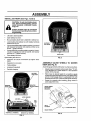
CAUTION:
Always disconnect
spark
plug wire and place wire where it cannot
contact spark plug in order to prevent
accidental starting when setting up,
transporting,
adjusting
or making
repairs.
Do not use grass catcher on steep slopes
2
PRODUCT
CONGRATULATIONS
on your purchase of a Sears
Tractor,. It has been designed, engineered and manufactured to give you the best possible dependability and
performance.
Should you experience any problem you cannot easily
remedy, please contact your nearest Sears Authorized
Service CentedDepartment.
We have competent, welltrained technicians and the proper tools to service or repair
this unit°
Please read and retain this manual The instructions will
enable you to assemble and maintain your unit property..
Always observe the "SAFETY RULES"°
MODEL
_IUMBER
SPECIFICATIONS
HORSEPOWER:
t5.0
GASOLINE CAPACITY
AND TYPE:
5 QUARTS
UNLEADED REGULAR
OIL TYPE (API-SG):
SAE 30 (above 32°F) o
SAE 5W-30 (below 32 F)
OIL CAPACITY:
3.0 PINTS
SPARK PLUG:
(GAP: .0XX")
CHAMPION RJ-19LM
STD361458
VALVE CLEARANCE:
INTAKE:
005" - 007"
EXHAUST: ,.009" - .01 t"
GROUND SPEED (MPH):
FORWARD:
1st
2rid
3rd
4th
5th
6th
REVERSE:
917257641
SERIAL
NUMBER
DATE OF PURCHASE
THE MODEL AND SERIAL NUMBERS WILL BE FOUND
ON A PLATE UNDER THE SEAT°
YOU SHOULD RECORD BOTH SERtAL NU MBER AND
DATE OF PURCHASE AND KEEP IN A SAFE PLACE
'FOR FUTURE REFERENCE.
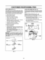
MAINTENANCE
RESPONSIBILITIES
Read and observe the safety rules.
•
Follow a regular schedute in maintaining,
using your unit.
•
Follow the instructions under"Customer
Responsibilities" and "Storage" sections of this owner's manual,
FRONT:
REAR:
14 PSi
t2 PSI
CHARGING SYSTEM:
3 AMPS BATTERY
5 AMPS HEADLIGHTS
30-35 FT. LBS,.
WARNING: This unit is equipped with an internal combustion engine and should not be used on or near any unimproved forest-covered, brush-covered or grass-covered
land unless the engine's exhaust system is equipped with
a spark arrester meeting applicable local or state laws (if
any)° If a spark arrester is used, it should be maintained in
effective working order by the operator°
AGREEMENT
-
TIREPRESSURE:
i BLADE BOLT TORQUE:
A Sears Maintenance Agreement is available on this product. Contact your nearest Sears store for details°
CUSTOMER
102
1,35
2.10
3..14
4,00
5.12
1,SB
tn the state of California the above is required by taw
(Section 4442 of the California Public Resources Code),
Other states may have similar laWSoFederal laws apply on
federal tandso A spark arrester for the muffler is available
through your nearest Sears Authorized Service Center/
Department (See REPAIR PARTS section of this manual)_
caring for and
LIMITED TWO YEAR WARRANTY ON ELECTRIC START RIDING EQUIPMENT
For two (2) years from the date of purchase, if this riding equipment is maintained, lubricated and tuned up according to the
instructions in the owner's manual, Sears will repair or replace, free of charge, any parts found to be defective in material or
workmanship
This Warranty does not cover:.
•
•
°
Expendable items which become worn during normal use, such as blades, spark plugs, air cleaners and belts.
Tire replacement or repair caused by punctures from outside objects, such as nails, thoms, stumps, or glass,
Repairs necessary because of operator abuse, negligence, improper storage or accident or the failure to maintain the
equipment according to the instructions contained in the owner's manual..
Riding equipment used for commercial or rental purposes.
LIMITED
90 DAY WARRANTY
ON BATTERY
For ninety (90) days from date of purchase, if any battery included with this riding equipment proves defective in material or
workmanship and our testing determines the battery wiltnot hold a charge, Sears will replace the battery at no charge.
WARRANTY SERVICE IS AVAILABLE BY RETURNING THE RIDING EQUIPMENT TO THE NEAREST
CENTER/DEPARTMENT IN THE UNITED STATES.
SEARS SERVICE
This Warranty gives you specific legal r_ghts,and you may also have other rights which may vary from state to state,
SEARS, ROEBUCK
AND COo, D/817 WA, HOFFMAN
3
ESTATES,
iLLINOIS
60179
TABLE OF CONTENTS
SAFETY RULES ............................................................ 2
PRODUCT SPECIFICATIONS ...................................... 3
CUSTOMER RESPONSIBILITIES ..................... 3, 15-19
WARRANTY .................................................................. 3
TABLE OF CONTENTS ...................................... ;......... 4
INDEX ............................................................................
4
TRACTOR ACCESSORIES .......................................... 5
ASSEMBLY .............................................................. 7-t0
OPERATION .......................................................... 11-14
MAINTENANCE SCHEDULE ...................................... 15
SERVICE AND ADJUSTMENTS ............................ 20-25
STORAGE ...................................................................
26
TROUBLESHOOTING ........................................... 27-28
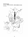
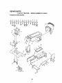
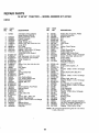
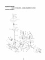
REPAIR PARTS - TRACTOR ................................ 30-47
REPAIR PARTS- ENGINE .................................... 48-52
PARTS ORDERING/SERVICE .................. BACK PAGE
INDEX
A
E
O
Accessories ...........................................................
5
Electrical:
Oil:
Adjustments=
Interlocks and Relays ..........................
24
Cold Weather Conditions ............
13,17
Brake ......................................................
22
Schematic ................................................
29
Engine ................................
17
Carburetor .................................................
25
Wiring Diagram .................................
30
Storage
26
Mower:
Engine:
Operation.................................
1i-i4
Front-To-Back ......................... 2!
AirFilter
.......................................................
18
Operating Mower. .......................................................
13
Side-To-Side ............................ 21
Air Screen ........................................................
18
Options:
Throttle Control Cable ..........................
24
Cooling Fins, Engine .................................
18
Accessories ...........................
5
Air Filter, Engine ................................................
t8
OiiChange .............................................
17
Spark Arrester
3,40
Air Screen, Engine ....................................................
18
Oil Level ........................................
13,17
P
Assembly .......................................................
7-10
OilType ...................................................
17
Parking Brake ..................................................
11-t2
B
Preparation ............................................
13
Paris Bag .....................................................................
6
Battery:
Repair Parts .........................................
48-52
Pads, Replacement/Repair ...................
30-47
Charging ...................................................
8
Starting .......................................................
14
Product Specifications.................................................
3
Cleaning ........................................................
17
Storage .....................................................
26
R
Installation..........................................................
9
F
Levels ......................................................
8,17
Filters:
Repair Parts ...............................
30-47
Preparation .........................................................
8
Air,
..........................................................
18
S
Starting with Weak Battery ................
23
Fuef .....................................................
19
Safety Rules ...............................
2
Storage .................................................................
26
Fuel:
Seat .....................................
8
Terminals ....................................................
17
Type ............................................................
13
Service and Adjustments ................
20-25
Belts:
Storage .......................................................
26
Brake .................................
22
Motion Drive
Fuse ..........................................................................
24
Carburetor. .............................
25
Removal/Replacement ................
22
G
Fuse .....................................................
24
Mower Blade Drive
Gauge Wheels ................................................................
9
Hood Removal/Installation .......... 24
Removal/Replacement ...............
22
H
Motion Drive Belt
Blade:
Hood
Removal/installation
........................
24
RemovaVReplacement ...............
22
Sharpening ...........................................
16
Mower Blade Ddve Belt
L
Replacement .................................................
16
Removal/Replacement ..............
22
Leveling Mower Deck ........................................
21
Brake Adjustment ...............................................
22
MowerAdjustment:
Lubrication Chart ......................................
15
C
Front-to-Back
21
M
CarburetorAdjustment ....................................
25
Side-to-Side
.........................................
21
Maintenance Schedule ...........................15
Controls, Tractor. .................................
11
Mower
Installation
20
Mower:
Customer Responsibilities ............. 15-19
Mower Removal ............................ 20
Adjustment,
Front-to-Back
..........
21
Engine:
Tire Care ..............................
8,16,23
Adjustment, Side-to-Side ..................
21
Air Filter .....................................................
18
Slope
Guide
Sheet
55
Blade Sharpening ............................
16
Air Screen, Engine ................................
18
Spark Plugs ......................................... 19
Blade
Replacement
............................
16
Battery ...........................................
17
Specifications ..........................................................
3
CuttingHeight..............................................
12
Cooling Fins, Engine .................t8
Starting the Engine
13-14
Installation
...............................................
20
Engine Oil ..............................................
t7
Steering Wheel .............................
7,23
Operation ........................................13
Fuel Filter .......................... :..... 19
Stopping the Tractor. ................................
12
Removal
....................................................
20
Spark Plugs .........................................
19
Storage ........................................................................
26
Mowing Tips .................................................
14
Tractor:.
T
Muffler'. ........................................................
19
Blades ......................................
16
Throttle
Controt
Cable
Adjustment ......24
Spark
Arrester
o.o_
...........................
3,40
Lubrication Chad .............................
15
Tires ...........................................................
8,16,23
MulcherPlate..................................................
I0
Maintenance Schedule ...............15
Trouble
Shooting
Chart
.....................
27-28
Tire Care ..................................
8,16,23
Transaxle
Repair
Pads
.......................
46-47
Cutting Height, Mower ........................................
12
W
Warranty ..................................
3
Wiring Diagram ..........................................
30
Wiring Schematic ..............................................
29
.................................................
....................................
........................................
.................................
......................................
.......................................
4
AND ATTACHMENTS
These accessories and attachments were availablethrough most Sears retail outletsand service centers when the tractorwas purchased,.
Most Sears stores can order these items for you when you provide the model number of your tractor,.
ENGINE
SPARK PLUG
MAINTENANCE
GAS CAN
FUEL STABILIZER
BLADES
BELTS
t
I
[
PERFORMANCE
Sears offersa wide variety of attachments that fit your tractor, Many ofthese are listedbelow with briefexplanations of how they can help
you. This list was current at the time of pubiicati0n; however, it may change in future years - more attachments may be added, changes
may be made in these attachments, or some may no longer be available or fit your model. Contact your nearest Sears store for the
accessories and attachments that are available for your tractor.
Most of these attachments do not require additional hitches or conversion kits (those that do are indicated) and are designed for easy
attaching and detaching.
AERATOR promotes deep root growth for a healthy lawn,, Tapered 2ob-inchsteel spikes mounted on 10-inch diameter discs
puncture holes in soil at close intervals to let moisture soak in
Steel weight tray for increased penetration.
BAGGER lets you collect grass clippings and leaves for a
healthier, neater looking lawn, Two Permanex containers hold
30-gallon plastic bags.,
BUMPER protects front end of tractorfrom damage,
CARTS make hauling easy. Variety of sizes available, pius
accessories such as side panel kits, tool caddy, cart cover,
protective mat and dolly.
CORING AERATOR takes small plugs out of soil to allow moisture and nutrients to reach grass roots. 36-inch swath° 24
hardened steel coring tips. 150 fb, capacity weight tray,
EASY OIL DRAIN VALVE makes oil changes easier, faster_
FRONT NOSE ROLLER cantersin front ofmower deckto reduce
chances of "scalping" on uneven terrain_
GANG HITCH lets youtow2 or3 pull-behind attachments at once,
such as sweepers, dethatchers, aerators (not for use with rollers,
carts or other heavy attachments)°
GAUGE WHEELS on both sides of the mower deck reduce
chances of "scalping" on uneven terraino For mower decks not so
equipped°
MULCH RAKE/DETHATCHER loosenssoil andffips thatch and
matted leaves to lawn surface for easy pickup. Twenty spdng tine
teeth., Useful toprepars bare areasforseeding. Available forfront
or rear mounting.
HIGH PERFORMANCE REEL-ACTION
SPRING TINE DETHATCHER covers 36-inch wide path and
tosses thatch into large hopper° Mounts behind tractor°
MULCHING CLOSE-OUT PLATE KIT, once installed, lets you
mulch, discharge or bag clippings (bagger optional) without
changing blades. For models not equipped as 3-in-1 Convertible
mowers. See 'MOWER in the Repair Parts section of this
manual.
RAMI 5 TOPS AND FEET let you load and unload tractor from a
pickup truck. Use with 2 x 8 or 2 x 10 lumber..
ROLLER for smoother lawn surface. 36-inch wide, IS-inch
diameterwater-tight drum holds up to 390 Ibs. ofweight. Rounded
edges prevent harm to turf. Adjustable scraper automatically
cleans drum.
SNOW BLADE forsnow removalonly, 14-inch high, 42-inch wide
blade clears 38-inch path when angled left or right,,Raises, lowers
withside lever. Adjustable skids; replaceable, reversible scraper
bar. (Use with tire chains and wheel weights and/or rear drawbar
weight,,)
SNOWTHROWER has 40-inch swath,, DnJm-typeauger handles
powdery and wet!heavy snow,, Mounts easily with simple pin
arrangement. Discharge chute adjusts from tractor seat. 6-inch
diameter spout discharges snow 10 to 50 feet. Liftcontrolled at
tractor seat. (Use with chains and wheel weights and/or rear
drawbarweight.)
SPRAYERS use 12-volt DC electric motor that connects to the
tractor battery or other 12-volt source. Includes booms for
automatic sprayingand hand held wand forspot spraying. Wand
has adjustable spray pattern. For applying herbicides, insectF
cides, fungicides and liquid fertilizers°
SPREADER/SEEDERS make seeding fertilizing, and weed kilF
ing easy. Broadcast spreaders are also useful for granular deicers and sand,.
SWEEPERS let you collect grass clippings and leaves.
TILLER has 5 hp engine and 36-inch swath to prepare seed beds,
cultivate and compost garden residue. Tiller has itsown built-in
lift and depth control system and does NOT require a sleeve hitch.,
Fits any lawn, yard or garden tractor,. Simply hook up to the tractor
drawbar and go_ Optional accessormes convert unit for
dethatching, aerating, hillingo..without tools.
TIRE CHAINS are heavy duty; closely spaced extra-large cross
links give smooth ride, outstanding traction1,
TRACTOR CAB has heavy duty vinyl fabric over tubular steel
frame, ABS plastictop; clear plastic windshield offers 360 degree
visibility. Hinged metal doors with catch. Keeps operator warm
and dry. Remove vinyl sides and windshields for use as sun
protector in summer. Optional accessories include, tinted/
tempe re dsolid safety glass windshieldwith hand operated wiper;
12-volt amber caution light for mounting on cab top,
VACS for po';verfulcollectionof heavy grass clippingsand leaves,,
Optional wand attachment to pick up debds in hard-to-reach
places,, VAClCHIPPER includes a chipper-shredder_
WEIGHT BRACKET for drawbar for snow removal applications.
Uses (1) 55 lb. weight.
WHEEL WEIGHTS for rear wheels provide needed traction for
snow removal or dozing heavy materials°
...................................
i i i i iiiiiiii
CONTENTS
iiiiiiiiii
iiiiiii
ii
iiiiiiiii
i,i_.........
OF HARDWARE
.............
,, ,, ,,,,,,,,,,,,,,,,
..........................
iiiiiiiii
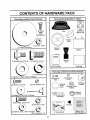
Parts Bag contents
PACK
LLI I
::::
i
Parts packed separately
shown full size
]
ii
in carton
ii ii
iiiiiiiiiiiii
@
@
(2) Sheet
Metal
Screws
#10-16 x 1/2
Battery acid
Seat
Mulcher
Plate
l
(1) Large Flat Washer
Steering
Wheel
llllllll
.===r
i
! W| milHUIF
(1) Shoulder Bolt 5/t6-18
Battery
!
Steering
Boot
(1) Hex Bolt !/2-13 x 1
',
I
,,
Owner's Manual
.....
| .....
Parts Bag
u Lii illll I,Nii
...................
i, ii
i
::
.11111
Parts bag contents not shown full size
..................
(1) LockWasher
iu ii iiiiiii
1/2
(1) Washer 17/32 x I-3/16 x 12 Gauge
II1'1
iii
_k
(2) Washers 3/16 x 3/4 x 16 Gauge
@
(2) Locknuts
3/8-i6
Steering
Wheel
Insert
(2) Lock Washers #10
(2) Screws #10 x 5/8
o
(2) Shoulder
Botts
_
Wheels
Steering Wheel
Adapter
(2) Gauge
Bushing
teering
(_
Assemblys
ill,,=
(2) Hex Bolts 1/4-20 x 3/4
"_
(2) Hex Nuts 1/4-20
........ ,4 _-_..._
,
(2) Keys
11
i
'
|
,/
(2) Washers
9132 x 5/8 x i6 Gauge
(2) Lock Washers 1/4
15° Slope Sheet
...................
6
iiiiii
Battery Caps
and Instructions
MBLY
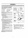
Your new tractor has been assembled at the factory with exception of those parts left unassembled for shipping purposes.
To ensure safe and proper operation of you r tractor all parts and hardware you assemble must be tightened securely. Use
the correct tools as necessary to insure proper tightness..
TOOLS
REQUIRED
FOR ASSEMBLY
A socket wrench set will make assembly easier, Standard
wrench sizes are listed.
(1) 5/16" wrench
(t) 3/4" Socket w/drive rachet
(2) 7/16" wrenches
Phillips Screwdriver
(1) 1/2" wrench
Tire pressure gauge
(1) 9/16" wrench
Utility knife
When right or left hand is mentioned in this manual, it
means when you are in the operating position (seated
behind the steering wheel).
TO REMOVE
TRACTOR
SCREW
FROM CARTON
UNPACKCARTON
.
°
.
Remove all accessible loose parts and parts cartons
from carton (See page 6)_
Cut, from top to bottom, along lines on all four corners
of carton, and lay panels flat.
ATTACH STEERING
°
°
°
POSITION)
Check for any additional loose parts or cartons and
remove°
BEFORE ROLLING
°
°
STEERING
SHAFT
TRACTOR
OFF SKID
STEERING
SHAFT
_HIPPING
POSITION)
WHEEL (See Fig. 1)
Slide the steering bushing over the steering shaft°
Raise steering shaft forward until screw holes in dash
line up with steering bushing_ Install two (2) sheet
metal screws and tighten securely.
FIG. 1
Position steering boot over steering shaft.
Place tabs of steering boot over tab slots in dash and
push down to secure°
Stide steering wheet adapter onto upper steering shafto
°
Position front wheels of the tractor so they are pointing
straight forward.
°
Position steering wheel so cross bars are horizontal
(left to right) and slide onto adapter.
°
Assemble large flat washer and 318-24 !ocknut and
tighten securely°
°
Snap steedng wheel insert into center of steering
wheel.
TO ROLL TRACTOR
OFF SKID (See Fig. 8)
Raise attachment lift lever to its highest position°
•
•
°
•
°
Remove protective plastic from tractor hood and grill.
IMPORTANT:CHECK FOR AND REMOVE ANY STAPLES
IN SKID THAT MAY PUNCTURE TIRES WHERE UNIT IS
TO ROL:L OFF SKID,
7
Release parking brake by depressing clutch/brake
pedal
Place gearshift lever in neutral (N) position,
Rol! unit backwards off skid°
Remove banding holding discharge guard up against
tracton
BLY
......................
HOW TO SET UP YOUR TRACTOR
PREPARE
BATTERY
I,HIIIIIIIIll
J
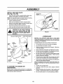
INSTALL SEAT (See Fig. 3)
Adjust seat before tightening adjustment bolt.
(See Fig. 2)
CAUTION: Wear eye and face shield.
Wash hands or clothing immediately If
accidentally in contact with batteryacid.
Do not smoke. Fumes from charged
battery acid are explosive.
Read the instructions included with the
batteryvent caps. Always wear gloves,
clothing and goggles to protect your
hands, skin and eyes.
Your unit has a battery charging system which is sufficient
for normal use. However, periodic charging of the battery
with an automotive charger will extend its life,.
.
See instructions packed with vent caps in parts bag°
.
Fitl battery with acid. Fill each cell until it reaches the
bottom of the vent wells° Do not overfill
o
=
Remove cardboard packing on seat pant
Place seat on seat pan and assemble shoulder bolt.
=
Assemble adjustment bolt, lock washer and flat washer
loosely Do not tighten.
•
Tighten shoulder bolt securely.
-
Lower seat into operating position and sit on seat.
•
Slide seat until a comfortable position is reached which
allows you to press clutch/brake pedal all the way
down°
•
Get off seat without moving its adjusted position.
o
Raise seat and tighten adjustment bolt securely.
\
II!
Allow battery to stand and settle for at least thirty
minutes° After standing, check the battery cell acid
level, if below the vent wells, add more acid until the
correct level is reached°
While battery is standing (after adding acid) and later, while
battery is being charged, continue with assembly of unit°
IMPORTANT:
TO MAXIMIZE
THE LIFE OF YOUR
BATTERY, IT IS NECESSARY THAT THE BATTERY BE
CHARGED
BEFORE
USE. FAILURE
TO CHARGE
BATTERY CAN RESULT IN A SHORTENED
BATTERY
LIFE_
o
C-
5
BOLT
Charge battery at a rate of 6 amperes for I hour. Use
a 12 volt battery charger. Observe all safety precautions required for battery charging,,
FIG. 3
°
Check the acid level after the battery is charged. If the
acid has fallen below the correct level, add distilled or
iron free water.
.
Install the vent caps to cover the vent wells. Wash the
top of the battery with water to remove any acid, then
wipe dry°
•
Check battery case for leakage to make sure that no
damage has occurred in handling.
°
Dispose of excess battery acid. Neutralize acid for
disposal by adding it to two gallons of water in a five
gallon plastic container, Stir with a wooden or plastic
paddle while adding baking soda until the addition of
more soda causes no more foaming.
CHECK DECK LEVELNESS
Follow instructions on how to install battery°
CHECK
BELTS
=
CHECK TIRE PRESSURE
The tires on your unit were ovennflated at the factory for
shipping purposes,. Correct tire pressure is important for
best cutting performance,.
°
Reduce tire pressure to PSi shown in "PRODUCT
SPECIFICATIONS" on page 3 of this manual.
For best cutting,results, mowerhousing should be properly
leveled. See 'TO LEVEL MOWER HOUSING in the
Service and Adjustments section of this manual
FOR PROPER
POSITION
OF ALL
See the figures that are shown for replacing motion and
mower blade drive belts in the Service and Adjustments
section of this manual Verify that the belts are routed
correctly
BATTERY
CELL ACID
LEVEL
CHECK BRAKE SYSTEM
After you learn how to operate your tractor, check to see
that the brake is properly adjusted. See ''TO ADJUST
BRAKE" in the Service and Adjustments section of this
manual
FIG. 2
8
ASSEMBLY
INSTALL
BATTERY
(See Figs. 4 and 5)
CAUTION: Do not short battery terminals. Before installing battery, remove
metal bracelets, wristwatch bands,
rings, etc.
Positive terminal must be connected
first to prevent sparking from accidental grounding.
-
Lift seat to raised position.
•
Open battery box door
•
Be sure battery drain tube is attached to battery box
=
Lower battery into battery box with battery terminals
toward front of unit,
°
First connect RED battery cable to positive (+)terminal
with hex bolt, flat washer, lock washer and hex nut as
shown. Tighten securely°
o
Connect BLACK grounding cableto negative (-) terminal with remaining hex bolt, flat washer, lock washer
and hex nut. Tighten securely.
Close battery box door°
,
BATtrER_
BOX DOOR
VENT CAPS
Open battery box door for:
FIG. 5
=
Inspection for secure connections (to tighten hardware).
°
Inspection for corrosion.
o
Testing battery.
•
°
Jumping (if required)°
Periodic charging.
ASSEMBLE
GAUGE
DECK (See Fig. 6)
WHEELS
TO MOWER
Assemble gauge wheels with tractor on a flat level surface,
BATTERY
BOX DOOR
POSITIVE
(RED) CABLE
NEGATIVE
(BLACK) CABLE
=
Adjust mower to desired cutting height (See "TO ADJUST MOWER CUTTING HEIGHT' in the Operation
section of this manual)°
°
With mower in desired height of cut position, gauge
wheels should be assembled so they are slightly off the
ground. Install gauge wheel in appropriate hole with
shoulder bolt and 3/8_16 Iocknut and tighten securely°
°
Repeat for opposite side installing gauge wheel in
same adjustment holeo
GAUGE WHEEL
MOUNTING
BRACKET
\
LOCK WASHER
HEX
BOLT
318-16
LOCKNUT
_._SHOULDER
GAUGE WHEEL"
POSITIVE (+) TERMINAL
NEGATIVE (.) TERMINAL
FIG. 6
FIG. 4
9
BOLT
BLY
INSTALL MULCHER PLATE
(See Figs. 7A & 7B)
=
DEFLECTOR
Install two latch hooks to mulcher plate using screw,
washer, lock washer, and weld nut as shown.
NOTE: Pre-assemble weld nut to latch hook by inserting
weld nut from the top with hook pointing down.
•
Tighten hardware securely,.
°
Raise and hold deflector shield in upright position_
•
Place front of mulcher plate over front of mower deck
opening and slide into place, as shown.
Hook front latch into hole on front of mower deck
•
Hook rear latch into hole on back of mower deck
Hll
i,
i iiiill
: :
................................
CAUTION: Do not remove discharge
guard from mower_ Raise and hold
guard when attaching mulcher plate
and allow it to rest on plate whde in
operation.
WELD NUT FROM THE TOP
LATCH
HOOKS
|
I
I
I
!
FIG. 7B
I
,/CHECKLIST
HOOK POINTS DOWN
\
WELD
BEFORE YOU OPERATE AND ENJOY YOUR NEW
TRACTOR, WE WISH TO ASSURE THAT YOU RECEIVE
THE BEST PERFORMANCE AND SATISFACTION FROM
THIS QUALITY PRODUCT
LOCK
WASHER
PLEA SE REVIEW THE FOLL 0 WING CHECKLIST:
,/
All assembly instructions have been completed°
,/
No remaining loose parts in carton.
#"
Battery is properly prepared and charged_ (Minimum
1 hour at 6 amps)o
,[
Seat is adjusted comfortably and tightened securely.
HOOK
,/
WELD
NUT
•[
All tires are properly inflated. (For shipping purposes,
the tires were ovednflated at tile factory).
Be sure mower deck is properly leveled side-to-side/
front-to-rear for best cutting results. (Tires must be
properly inflated for leveling)
LATCH
LOCK
WASHER
WASHER
_" Check mower' and drive belts. Be sure they are routed
properly around pulleys and inside all belt keepers.
,z Checkwiringo See that all connections are still secure
and wires are properly clamped.
WASHER
MULCHER
PLATE
\_.
SCREW
WHILE LEARNtNG HOW TO USE YOUR TRACTOR, PAY
EXTRA A TTENT!ON TO THE FOLLOWING IMPORTANT
ITEMS:
FIG. 7A
TO CONVERT TO BAGGING
DISCHARGING
OR
Simply remove mulcher plate and store in a safe place.
Your mower is now ready for discharging or installationof
optional grass catcher accessory,
v"
Engine oil is at proper level.
J
Fuel tank is filled with fresh, clean, regular unleaded
gasoline.
Become familiar with all controls - their location and
function. Operate them before you start the engine.
Be sure brake system is in safe operating condition.
v"
,/
10
O
....
KNOW
YOUR
i
lul
iii Ullll,i iiiii
Li i
ii
iiiiiii
......................
TRACTOR
READ THIS OWNER'S
MANUAL AND SAFETY RULES BEFORE OPERATING
YOUR TRACTOR
Compare the illustrationswithyour tractorto familiarize yourself with the locationsof va rious controlsand adjustments° Save
this manual for future reference°
IGNITION
SWITCH
UFTLEVER
PLUNGER
ATTACHMENT
L|FTLEVER
THROTTL_CHOKE
CONTROL
ATTACHMENT
LEVER
l\l
CLUTCH/BRAKE
PEDAL
i_
r'_
,,
PARKING BRAKE
HEIGHT
ADJUSTMENT
KNOB
GEARSHIFT
LEVER
FIG. 8
Our tractors conform to the safety standards of the American National Standards institute.
ATTACHMENT CLUTCH LEVER: Used to engage the
mower blades, or other attachments mounted to your
tractor.
GEARSHIFT LEVER: Selects the speed and direction of
tractor.
ATTACHMENT LIFT LEVER: Used to raise and lower the
mower deck or other attachments mounted to your tractor,
LIFT LEVER PLUNGER: Used to release attachment tift
lever when changing its position.
LIGHT SWITCH: Turns the headlights on and off.
THROTTLE/CHOKE CONTROL: Used for starting and
controlling engine speed.
CLUTCH/BRAKE PEDAL: Used fordeclutching and braking.the tractor and starting the engine°
PARKING BRAKE: Locks clutch/brake
brake position
IGNITION SWITCH:
engine,
pedal into the
Used for starting and stopping the
HEIGHT ADJUSTMENT KNOB: Used to adjustthe mower
cutting heighL
11
The operation of any tractor can result in foreign objects thrown into the eyes, which
can result in severe eye damage.
Always wear safety glasses or eye shields while
operating your tractor or performing any adjustments or repairs. We recommend a wide
I
I
I
vision safety mask for over the spectacles or standard safety glasses.
I
.....
HOW TO USE YOUR
TO SET PARKING
i
TRACTOR
BRAKE (See Fig. 9)
•
Depress clutch/brake pedal intofull "BRAKE" position
and hold.
•
Place parking brake lever in"ENGAGED"position and
release pressure from clutch/brake pedal. Pedal should
remain in "BRAKE" position.. Make sure parking brake
will hold vehicle secure.
STOPPING
I"1111
iiiiiii
...................................
o
Move gearshift and range shift levers to desired position.
°
Slowly release clutch/brake pedal to start movement.
IMPORTANT:
BRING TRACTOR TO A COMPLETE STOP
BEFORE SHIFTING OR CHANGING GEARS, FAILURE
TO DO SO WILL SHORTEN THE USEFUL LIFE OF YOUR
TRANSAXLE.
(See Fig. 9)
Move attachment clutch lever to"DISENGAGED"
sitiono
GROUND DRIVE -
ATTACHMENT CLUTCH LEVER
"ENGAGED" POSITION
"DISENGAGED"
POSITION
po-
PARKING BRAKE
'ENGAGED" POSITION
"BRAKE"
POSITION
°
Depress clutch/brake pedal intofuII"BRAKE" position.
,
Move gearshift lever to neutral (N) position.
ENGINE -
GEARSHIFT
LEVER
Move throttle control to slow 0 position.
NOTE: Failure to move throttle control to slow 0 position
and allowing engine to idle before stopping may cause
engine to "backfire".
o
•
"DISENGAGED"
POSITION
Turn ignition key to "OFF' position and remove key.
Always remove key when leaving tractor to prevent
unauthorized use.
CLUTCH/BRAKE PEDAL
"DRIVE" POSITION
TO ADJUST MOWER CUTTING
(See Fig. 9)
IIII
II
TO USE THROTTLE
IIIIIIII1'
I
iiiii
CONTROL
...........................
°
Turn knob clockwise ((_)
Turn knob counterclockwise (P--_) to lower cutting
height.
to raise cutting height.
The cutting height range is approximately 1-1/2" to 4"o The
heights are measured from the ground to the blade tip with
the engine not running° These heights are approximate
and may vary depending upon soil conditions, height of
grass and types of grass being mowed.,
(See Fig. 9)
Operating engine at less than full throttle reduces the
battery charging rate.
Full throttle offersthe best bagging and mowerperformance.
TO MOVE FORWARD
(See Fig. 9)
HEIGHT
:
Always operate engine at full throttle_
•
KNOB
The cutting height is controlled by turning the height adjustment knob in desired direction.
CAUTION: Always stop tractor completely, as described above, before leaving the operator's position; to empty
grass catcher, etc.
IIIIIIII
HEIGHT ADJUSTMENT
FIG, 9
Never use choke to stop engine.
NOTE: Under certain conditions when tractor is standing
idle with the engine running,hot engine exhaust gases may
cause "browning" of grass. To eliminate this possibility,
always stop engine when stopping tractor on grass areas.
°
I
Start tractor with clutch/brake pedal depressed and
gearshift lever' in neutral (N) position_
THROTTLFJ
CHOKE
CONTROL
•
i
°
MOWER BLADES -
,
I
•
The ave.ra.gelawn should be cut to approximately 2-1/2
inches during the cool season and to over 3 inches
during hot months. For healthier' and better looking
lawns, mow often and after moderate growth.
°
For best cutting performance, grass over6 inches in
height should be mowed twice° Make the first cut
relatively high; the second to desired height°
AND BACKWARD
The direction and speed of movement is controlledby the
gearshift lever°
12
OPERATION
Hll
TO OPERATE
ii1//
ill
.........................
ilml_lll
MOWER (See Fig. 10)
-
Your unit is equipped with an operator presence sensing
switch. Any attempt by the operator to leave the seat with
the engine running and the attachment clutchengaged will
shut off the engine.
•
=
Select desired height of cut..
Lower mower with attachment lift control.
.
Start mower blades by engaging attachment clutch
control.
°
TO STOP MOWER BLADES - disengage attachment
clutch control,.
•
=
u
ill illl_l
Move gearshift lever to 1st gear. Be sure you have
allowed room for tractor to roll slightly as you restart
movement.,
To restart movement, slowly release parking brake and
clutch/brake pedal.
Make all turns slowly.,
TO TRANSPORT
without either the entire grass catcher,
CAUTION:
on
mowers Do
so not
equipped,
operate or
thethe
mower
discharge guard tn place.
ATTACHMENT CLUTCH LEVER
"DISENGAGED" POSITION
"ENGAGED"
POSITION
ii
•
Raise attachment lift to highest position with attachment lift control
•
When pushing or towing your tractor, be sure gearshift
lever is in neutral (N) position,
°
Do not push or tow tractor at more than five (5) MPH.
NOTE: To protect hood from damage when transporting
your tractor on a truck or a trailer, be sure hood is closed and
securedtotractoro Use an appropriate meansoftying hood
to tractor (rope, cord, etc.,).
BEFORE STARTING THE ENGINE
ATTACHMENT
UFT LEVER
HIGH PosmoN
CHECK ENGINE OIL LEVEL (See Fig. 16)
•
The engine in your tractor has been shipped, from the
factory, already filled with summer weight oil
•
Check engine oil with tractor on level ground°
.
Remove oil fill cap/dipstick and wipe clean, reinsert the
dipstick and screw cap tight, wait for a few seconds,
remove and read oil level, if necessary, add oil until
"FULL" mark on d{pstick is reached. Do not overfill.,
°
For cold weather operation you should change oil for
easier starting (See "OIL VISCOSITY CHART' in the
Customer Responsibilities section of this manual).
.
To change engine oil, see the Customer Responsibilities section in this manual.
ADD GASOLINE
•
Fil! fuel tank° Use fresh, clean, regular unleaded
gasoline. (Use of leaded gasoline will increase carbon
and lead oxide deposits and reduce valve life),
IMPORTANT: WHEN OPERATING IN TEMPERATURES
BELOW 32°F(0°C), USE FRESH, CLEAN WINTER GRADE
GASOLINE TO HELP INSURE GOOD COLD WEATHER
STARTING.
FIG. t0
TO OPERATE
IA
°
.......................
....
ON HILLS
WARNING: Experience indicates that alcohol blended
fuels (called gasohol or using ethanol or methanol) can
attract moisture which leads to separation and formation of
acids during storage, Acidic gas can damage the fuel
system of an engine while in storage° To avoid engine
problems, the fuel system should be emptied before storage of 30 days or longer. Drain the gas tank, start the
engine and let it run until the fuel lines and carburetor are
empty. Use fresh fuel next season. See Storage instructions for additional information, Never use engine or
carburetor cleaner products in the fuel tank or permanent
damage may occur.
CAUTION: Do not drive up or down
hills with slopes greater than 15 ° and
do not drive across any slope.
Choose the slowest speed before starting up or down
hJlls_
-_ Avoid stopping or changing speed on hi!lso
•
If slowing is necessary, move throttle control lever to
slower position.
tf stopping is absolutely necessary, push clutch/brake
pedal quickly to brake position and engage parking
Drake.
I
13
Am,JIL
_
filler neck. Do notoverfill. Wipeoffany
spilled
oil orFill
fuel.
not store,
spill
or
CAUTION;
to Do
bottom
of gas
tank
use gasoline near an open flame.
i
• iHi.......
!
I
OPERATION
ul_ujt
TO START
ENGINE
(See Fig, 9)
•
When starting engine for the first time or if engine has run
out of fuel, it will take extra cranking time to move fuel from
the tank to the engine.
,
•
Depress clutch/brake pedal and set parking brake.
Place gearshift lever in neutral (N) position°
o
°
Move attachment clutch to "DISENGAGED" position.
Move throttle control lever to choke (N) position for
cold engine start. For warm engine start, move throttle
control to fast (,1_)position.
o
=
=
f
Insert key into ignition andtum key clockwise to"START"
position and release key as soon as engine starts. Do
not run starter continuously for more than fifteen
seconds per minute, tf engine does not start after
several attempts, move throttle control to fast (,_)
position, wait a few minutes and try again.
When engine starts, move throttle control to desired
position°
MULCHING
°
The special mulching blade will recut the grass clippings many times and reduce them in size so that as
they fall onto the lawn they will disperse intothe grass
and not be noticed° Also, the mulched grass will
biodegrade quickly to provide nutrientsfor the lawn.
Always mulch with your highest engine (blade) speed
as this will provide the best recutting action of the
blades..
•
Avoid cutting your lawn when it is wet. Wet grass tends
to form clumps and interferes with the mulching action..
The best time to mow your lawn isthe early afternoon.
At this time the grass has dried and the newly cut area
wilt not be exposed to the direct sun_
°
Forbest results, adjust the mower cutting height so that
the mower cuts off only the top one-third of the grass
blades (See Fig. 12).. For extremely heavy mulching,
reduce your width of cut and mow slowly.
°
Certain types of grass and grass conditions may require that an area be mulched a second time to completely hide the clippings. When doing a second cut,
mow across or perpendicular to the first cut path°
=
Change your cutting pattern from weekto week. Mow
north to south one week then change to east to west the
next week.. This will help prevent matting and graining
of the lawn.
MOWING TIPS
•
Mower should be properly leveled for best mowing
performance. See "TO LEVEL MOWER HOUSING" in
the Service and Adjustments section of this manual
The teft hand side of mower should be used for trimming.
Drive so that clippings are discharged onto the area
that has been cut. Have the cut area to the right of the
machine. This will result in a more even distribution of
clippings and more uniform cutting.
°
°
o
°
°
=
MOWING TIPS
IMPORTANT:
FOR BEST PERFORMANCE, KEEP
MOWER HOUSING FREE OF BUILT-UP GRASS AND
TRASH. CLEAN AFTER EACH USE.
NOTE: If at a high altitude (above 3000 feet) or in cold
temperatures (below 32°F), the carburetor fuel mixture
may need to be adjusted for best engine performance.. See
"TO ADJUST CARBURETOR" in the Service and Adjustrnents section of this manual.
Tire chains cannot be used when the mower housing
is attached to unit.
-,
FIG. 11
Allow engine to warm up for a few minutes before
engaging drive or attachments.
°
When operating attachments, select a ground speed
that will suit the terrain and give best performance of
the attachment being used_
When mowing large areas, start by turning to the right
so that clippings will discharge away from shrubs,
fences, driveways, etc. After one ortwo rounds, mow
in the opposite direction making left hand turns until
finished (See Fig. 11 ).
if grass is extremely tall, it should be mowed twice to
reduce load and possible fire hazard from dried clipc_ings. Make first cut relatively high; the second to the
esired heighL
Do not mow grass when it is wet. Wet grass wilt plug
mower and leave undesirable clumps° AUow grass to
dry before rnowing_
I
MAX 1/3
Always operate engine at full throttle when mowing to
assure better mowing performance and proper discharge of material. Regulate ground speed by selecting a low enough gear to give the mower cutting
performance as well as the quality of cut desired.
FIG. 12
14
t]
.::,,::::
.........
LITIES
RESPONSi
CU
ull i mllllllll
..............
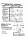
AS YOU COMPLETE
_0_
T
Check Brake Operation
Check Tire Pressure
Check for Loose Fasteners
R
Sharpen/RePlace
Mower Blades
_
_._,_,
:....................
......
_,_x; £,_._._0"_.
._,_, ._
I
LubricationChart..................
T Check Battery Level/Recharge
0
Clean Battery and Terminals
a , CheckTrans.axleCooling
Adjust Blade Belt(s) Tenston
........
Adjust Motion Drive Belt(s)Tension
Check EngineOil Levei
Change Engine Oil
NE Clean
Glean Air Screen
Fil.te.r
V'
.........
..................
......
G
Inspect MuffierlSparkArrester
I
Replace Oil Filter (if equipped)
N
Clean Engine Cooling Fins .....
_........
Replace Spark plug .......
Replace Air Filter Paper Cartridge
Replace Fuel Filter
1 _ Change mere often when operating under a heavy load or in high ambient temperatures
2 _ Service more often when operating In dirty or dusty conditions,
GENERAL
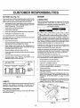
LUBRICATION
RECOMMENDATIONS
The warranty on this tractor does not cover items that have
been subjected to operator abuse or negligence, To
receive full value from the warranty, operator must maintain
tractor as instructed in this manual°
(_)SPINDLE
Some adjustments will need to be made periodically to
properly maintain your tractor..
Al! adjustments in the Service and Adjustments section of
this manual should be checked at least once each season.
BEARING
,
(_
Once a yearyou should replace the spark plug, clean
or replace air filter, and check blades and belts for
wear° A new spark plug and clean air filter assure
proper air-fuel mixture and help your engine run better
and last longer.,
BEFORE
3 - If equipped with ell filter, change e{I every 50 hours
4 - Replace blades more e{ten when mowing in sandy sol[
5 - tf equipped with adjustable system
FRONT
CHART
--
ZERK_
WHEEL_
ZERK
SPINDLE ZERK 0
FBONT
W.EEL@
_:} :::::::::::::::::::::::::
BEARING
_
_
ZERK
ENGINE
@
(_ ATTACHMENT"
CLUTCH
PIVOT(S)
EACH USE
°
=
Check engine oil level
Check brake operation,.
=
-
Checktire pressure.
Check for loose fasteners.
(_
SAE 30 OR 10W30 MOTOR OIL API _ SG
(_) GENERAL PURPOSE GREASE
(_) REFER TO CUSTOMER RESPONSIBILITIES "ENGINE" SECTION
IMPORTANT:
DO NOT OIL OR GREASE THE PIVOT POINTS
WHICH HAVE SPECIAL NYLON BEARINGS.
VISCOUS LUBRICANTS WILL ATTRACT DUST AND DIRT THAT WILL SHORTEN
THE LIFE OF THE SELF-LUBRICATING
BEARINGS
IF YOU
FEEL THEY MUST BE LUBRICATED,
USE ONLY A DRY, POW15
DERED GRAPHITE
TYPE LUBRICANT
SPARINGLY.
TRACTOR
BLADE
Always observe safety rules when performingany maintenance°
MANDREL
;EMBLY
BRAKE OPERATION
tf tractor requires more than six (6) feet stopping distance
at high speed in highest gear, then brake must be adjusted.
(See "TO ADJUST BRAKE" in the Service and Adjustments section of this manual),.
TRAILING
EDGE
FLAT WASHER
TIRES
.
LOCK WASHER_
Maintain proper air pressure in all tires (See "PRODUCT SPECIFICATIONS" on page 3 of this manual),,
°
Keep tires free of gasoline, oil, or insect controlchemica(s which can harm rubber.
°
Avoid stumps, stones, deep ruts, sharp objects and
other hazards that may cause tire damage,,
HEX BOLT
*A GRADE 8 HEAT TREATED BOLT CAN BE
IDENTIFIED BY SIX LINES ON THE BOLT HF.,AD_
FIG. 13
BLADE CARE
For best results mower blades must be kept sharp_ Replace bent or damaged blades.
BLADE REMOVAL
TO SHARPEN
Care should be taken to keep the blade balanced An
unbalanced blade will cause excessive vibration and eventual damage to mower and engine
(See Fig. 13)
°
Raise mower to highest position to allow access to
blades_
°
Remove hex bolt, tockwasher and flat washer securing
blade°
•
Install new or resharpened blade with trailing edge up
towards deck as shown°
°
Reassemble hex bolt, lock washer and flat washer in
exact order as shown,,
BLADE (See Fig. 14)
°
o
°
= Tighten bolt securely (30-35 F:t.Lbs. torque).
IMPORTANT: BLADE BOLT IS GRADE 8 HEATTREATED_
NOTE: We do not recommend sharpening blade- but if you
do, be sure the blade is balanced.
The blade can be sharpened with a file or on a grinding
wheel, Do not attempt to sharpen while on the mower.
To check blade balance, you will need a 5/8" diameter
steel bolt, pin, or acone balancero (When using acone
balancer, follow the instructions supplied with balancer).
Slide blade on to an unthreaded portion of the steel bolt
or pin and hold the bolt or pin parallel with the ground.
If blade is balanced, it should remain in a horizontal
position, if either end of the blade moves downward,
sharpen the heavy end until the blade is balanced,
NOTE: Do not use a nail for balancing blade. The lobes of
the center hole may appear to be centered, but are noL
CENTER HOLE
OR PIN
/
/
FIG, 14
16
/
CUSTOMER
iiii
i i,i1,11,1
..........
BATTERY
RESPONSIBILiTI
_ _.......
ii
i,
iiiiii
..............
_,,,,_,,,,_ ................
ENGINE
(See Fig. 15)
Your tractor has a battery charging system which is suffF
cient fer normal use° However, periedic charging of the
battery with an automotive charger will extend its life.
= Acid solution level in each battery cell should be even
with bottoms of vent wells. Add only distilledoriron free
water if necessary_ Do not overfill
.
°
Keep battery and terminals cleano
Keep battery bolts tight°
°
Keep vent caps tight and small vent holes incaps open,
LUBRICATION
Only use high quality detergent oil rated with API service
classification SG. Select the oil's SAE viscosity grade
according to your expected operating temperature.
•','_l,_
iOF
°
II
Recharge at 6 amperes for I hour.
-20 °
40 °
80=
Corrosion and dirt on the batter,] and terminals can cause
the battery te "leak" power.
NOTE: Although multiwiscosity oils (5W30, IOW30 etc°
improve starting in cold weather, these multi-viscosity oils
wilt result in increased oil consumption when used above
32°F_ Check your engine ell level more frequently to avoid
possible engine damage from running low on oil
°
o
Rinse the battery with plain water and dry.
°
°
Clean terminals and battery cable endswith wire brush
until bright.
Coat terminals with grease or petroleum jelly,
"
As_biysecti(_n'ofthsmanua,).,Reinstal'
batterv (S eel"INSTALL BATTERY" in the
RANGEANTICIPATEDBEFORE
20"
NEXT
30"
40 °
OILCHANGE
Change the oil after the first two hours of operation and
every 25 hours thereafter or at least once a year if the
tractor is not used for 25 hours in one year,,
Check the crankcase oil level before starting the engine
and after each eight (8) hours of operation° Tighten oil fill
cap/dipstick securely each time you check the oil level.
TO CHANGE ENGINE OIL (See Fig. 16)
Determine temperature range expected before oil change.
All oil must meet API service classification SG,,
CUT AWAY VIEW
VENT
WELL CAP
VENT
BATTERY
CELL ACID
LEVEL
•
Be sure tractor is en level surface.
•
°
Oil will drain more freely when warm.
Catch oil in a suitable container°
•
Remove oil fill cap/dipstick. Be careful not to allow dirt
to enter the engine when changing oil.
o
Remove drain plug.
°
After oil has drained completely, replace oil drain plug
and tighten securety_
•
Refill engine with oil through oil fill dipstick tube. Pour
slowly. Do not overfill, For approximate capacity see
PRODUCT SPECIFICATIONS
on page 3 of this
manual,,
•
Use gauge on oil fill cap/dipstick for checking level. Be
sure dipstick cap is tightened securely for accurate
reading. Keep oil at "FULL" line on dipstick.
FIG. 15
V-BELTS
Check V_beltsfor deteriorationand wear after 100 hours of
operation and replace if necessary_ The belts are not
adjustable. Replace belts if they begin to slip from wear,,
TRANSAXLE
10'
100 °
TEMPERATURE
Disconnect BLACK battery cable first then RED battery cable and remove battery from tractor,,
Wash battery with solution of four tablespoons of
baking sodato one gallon of water. Becareful notto get
the soda solution into the cells°
0°
60 =
i
.
-10 °
32°
TO CLEAN BATTERY AND TERMINALS
Open battery box door°
-20 °
30 =
-
.
"
0'
i°C
FILL
CAPIDIPSTICK
COOLING
Keep transaxle fre_from build-up of dirt and chaff which
can restrict cooling,,-,
OIL DRAIN
PLUG
FIG. 16
17
CUSTO
SIBILITi
................
.......
.....
iiii1,111
iiiii
II
IIII1'
III
AIR FILTER (See Fig. 17)
CLEAN AIR SCREEN (See Fig. 18)
'(our engine will not run properly using a dirty air fi_ter_.
Clean the foam pre-cleaner after every 25 hours of operation or every season. Service paper cartridge every 100
hoursof operation or every season, whichever occursfirst°
Air screen must be kept free of dirt and chaff to prevent
engine damage from overheating° Clean with a wire brush
or compressed air to remove dirt and stubborn dried gum
fibers.
Service air cleaner more often under dusty conditions.
ENGINE COOLING
•
Remove knob(s) and cover.
TO SERVICE PRE-CLEANER
FINS (See Fig. 18)
Remove any dust, dirt or oil from engine cooling fins to
prevent engine damage from overheating°
°
Remove screws from blower housing and lift housing
and dipstick tube assembly off engine°
•
Slide foam pre-cleaner off cartridge.
=
Wash it in liquid detergent and water..
o
°
Squeeze it dry in a clean cloth_
Saturate it in engine oil. Wrap it in clean, absorbent
cloth and squeeze to remove excess oil
•
•
Cover' oil fill opening to prevent entry of dirL
Use compressed air orstiff bristle brush to thoroughly
clean engine cooling fins.
°
if very dirty or damaged, replace pre-cteanero
•
To reassemble, reverse above procedure.,
°
Reinstallpre-cleanerovercartridgeo
°
Reinstall cover and secure with knob(s).
TO SERVICE CARTRIDGE
,
°
Remove cartridge nut..
Carefully remove cartridge to prevent debris from entedn_ carburetor. Clean base carefully to prevent
debris from entering carburetor.
o
Clean cartridge bytapping gentlyon flat surface_ Ifvery
dirty or damaged, replace cattridge_
SCREWS
BLOWER
HOUSING
SCREWS
AIR SCREEN
DIPSTICK
TUBE
ASSEMBLY
°
Reinstall cartridge, nut, precleaner, cover and secure
with knob(s)..
IMPORTANT;
PETROLEUM SOLVENTS, SUCH AS
KEROSENE, ARE NOT TO BE USED TO CLEAN THE
CARTRIDGE. THEY MAY CAUSE DETERIORATION OF
THE CARTRIDGE. DO NOT OIL CARTRIDGE, DO NOT
USE PRESSURIZED
AIR TO CLEAN OR DRY
CARTRIDGE_
PLUG
COVER KNOB
ENGINE COOLING FINS
FIG. 18
CARTRIDGE NUT
COVER _
PAPER
CARTRIDGE
- LEANE.
.........
FIG. 17
18
CUSTOMER
RESPONSIBILITIES
MUFFLER
inspect and replace corroded muffler and spark arrester (if
equipped) as it could create a fire hazard and/or damage,.
SPARK
PLUGS
Replace spark plugs at the beginning of each mowing
season or after every t00 hours of operation, whichever
occurs first. Spark ptug type and gap setting are shown in
"PRODUCT SPECIFICATIONS" on page 3 of this manual.
IN-LINE FUEL FILTER
CLAMP
(See Fig. 19)
FIG. 19
The fuel fittershould be replaced once each season_ If fuel
filter becomes clogged, obstructing fuel flow to carburetor,
replacement is required..
=
Place new fuel filter in position in fuel line with arrow
pointing towards carburetor.
°
Be sure there are no fuel line leaks and clamps are
properly positioned.
immediately wipe up any spilled gasoline..
°
CLEANING
With engine cool, remove filter and plug fuel line
sections.
o
CLAMP
•
C1ean engine, battery, seat, finish, etc. of all foreign
matter_
°
Keep finished surfaces and wheels free of allgasoline,
oil, etc.
.
Protect painted surfaces with automotive type wax.
We do not recommend using a garden hose to clean your
tractor unless the electrical system, muffler, air filter and
carburetor are covered to keep water out. Water in engine
can result in a shortened engine life..
19
CAUTION:
o
o
Q
•
•
•
BEFORE PERFORMING ANY SERVICE OR ADJUSTMENTS:
Depress clutch/brake pedal fully and set parking brake.
Place gearshift lever in neutral (N) position.
Place attachment clutch in "DISENGAGED" position.
Turn ignition key "OFF" and remove key.
Make sure the blades and all moving parts have completely stopped.
Disconnect spark plug wire from spark plug and place wire where it cannot come in contact with
plug.
TRACTOR
TO REMOVE
MOWER (See Fig. 20)
LEVER
Mower willbe easier to remove from the right side oftractor
•
°
o
Place attachment clutch in "DISENGAGED" position_
Move attachment lift lever forwardto lower'mower to its
towest position_
Rol! belt_off engine pulley.
=
Disconnect clutch rod from clutch lever by removing
retainer spring.
•
Disconnect anti-sway bar from chassis bracket by
removing retainer spring°
Disconnect suspension arms from rear deck brackets
by removing retainer springs..
Disconnect front links from deck by removing retainer
springs.
=
,
°
SPRING
SUSPENSION
ARMS
SPRINGS
Raise lift lever to raise suspension arms. Slide mower
out from under tractor.
RETAINER
SPRING
IMPORTANT:
IF AN ATTACHMENT OTHER THAN THE
MOWER IS TO BE MOUNTED TO THE TRACTOR. THE
R.H. AND L,.H. SUSPENSION ARMS MUST BE REMOVED
FROM TRACTOR.
TO INSTALL
ANTI-SWAY BAR
RETAINER
SPRINGS
(BOTH SIDES)
MOWER (See Fig. 20)
.
,
Raise attachment lift lever to its highest position.
Slide mowerundertractorwithdischarge
guardto right
side of tractor.
.
°
Lower lift lever to its lowest position.
Install mower in reverse order of removal instructions_
ENGINE
PULLEY
FIG. 20
20
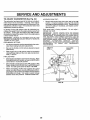
SERVICE AND ADJUSTM
TO LEVEL MOWER
HOUSING
FRONT-TO-BACK ADJUSTMENT (See Figs° X3 and X4)
IMPORTANT; DECK MUST BE LEVEL SIDE-TO-SIDE. IF
THE FOLLOWING FRONT-TO-BACK ADJUSTMENT IS
NECESSARY, BE SURE TO ADJUST BOTH FRONT LINKS
EQUALLY SO MOWER WSLL STAY LEVEL SIDE-TOSIDE.
To obtain the best cutting results, the mower housing
shouldbe adjusted so that the front is approximately 1/4" to
3/4" lower than the rear when the mower is in its highest
position.
Check adjustment on right side of tractor. Measure distance"D" directly in front and behind the mandrel at bottom
edge of mower housing as shown,
•
Before makingany necessaryadjustments, checkthat
both front links are equal in length. Both links should
be approximately 10-3/8",,
•
If links are not equal in length, adjust one link to same
length as other link,
° To lower front of mower loosen nut "E" on both front
links an equal number of turns.
.
When distance "D" is 1/4" to 3/4" lower at front than
rear, tighten nuts "F" against trunnion on both front
links°
° To raise front of mower, loosen nut"F" fromtrunnion on
both front links° Tighten nut "E" on both front links an
equal number of turns°
° When distance "D" is 1/4" to 3/4" lower at front than
rear, tighten nut"F" against trunnion on both front links.
°
Recheck side-to-side adjustment.
Adjust the mower while tractor is parked on level ground or
driveway.
Make sure tires are properly inflated (See
"PRODUCT SPECIFICATIONS" on page 3),, If tires are
over or under inflated, you will not properly adjust your
mower_
SIDE-TO-SIDE ADJUSTMENT (See Figs_21 and 22)
You will need two (2) standard 2 x 4 short pieces of wood
to make the following adjustment. Similar blocks measuring t-1/2" thick may also be used.
= Raise mower with attachment lift control to allow two
(2) 1-!/2" thick blocks to be placed under rear edge of
mower°
= Place one block directly behind the left mandrel Place
the remaining block under the stamped ridge on the
right rear edge of mower deck.,
°
Lower mower deck to its lowest height of cut position
(See"TO ADJUST MOWER CUTTING HEIGHT" inthe
Operation section of this manual).
° On both sides of tractor, loosen, but do not remove, the
fasteners securing the adjustable pivot brackets to
frame. Both brackets must be loose enough to move
freely.
o Pull down firmly on suspension arm to remove any
slack in pivot bracket and hold while tightening rear
fastener first to secure° Tighten remaining fastener,,
°
Repeat procedure on other side of tractor.
°
Raise mower with attachment lift control and remove
blocks from under mower.
MANDREL
PLACE TWO (2) I-1/2" THICK BLOCKS UNDER REAR EDGE OF
DECK (USE WOOD 2 X 4'S OR EQUIVALENT)
DIRECTLY
BEHIND
FIG. 23
MANDREL _
BOTH FRONT LINKS MUST BE EQUALIN
LENGTH
UNDER
STAMPED
RIDGE
MOWER MUST BE IN LOWEST HEIGHT OF CUT POSITION
FIG. 21
NUT "E"
NUT
PULL DOWN AND TIGHTEN REAR FASTENER FIRST
FRONTLINKS
FIG. 22
2'1
TRUNNION
FIG. 24
ii1,11,11,
: ::
......................
S
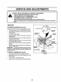
TO REPLACE
(See Fig. 25)
C
MOWER
•
i i ii
,11,111
lull
I
inln
..................
L
ADJUSTMENTS
BLADE DRIVE BELT
WITH PARKINGBRAKE "ENGAGED"
The mower blade drive belt may be replaced withouttools.
Park the tractor on tevel surface. Engage parking brake,
BELT REMOVALo
°
Place attachment clutch in "DISENGAGED" position.
Move attachment lift lever forward tolower mowerto its
lowest position,
•
Roll belt off engine pulley_
°
°
Work belt off both mandrel pulleys and idler pulleys.
Pull belt away from mower.
NUT "A"
BELT INSTALLATION = install new belt in reverse order of removal
o
Make sure belt is in all pulley grooves and inside all belt
guides,
FIG. 26
ENGINE PULLEY
MANDREL
PULLEY
IDLER
PULLEYS
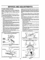
TO REPLACE
(See Fig, 27)
MOTION DRIVE BELT
Park the tractor on level surface,, Engage parking brake,,
For assistance, there is a belt installation guide decal on
bottom side of left footrest,
MANDREL
PULLEY
Remove mower (See "TO REMOVE MOWER" in this
section of this manuaL)
°
Remove upper belt keeper'.
°
°
Remove belt from stationary idler and clutching idler',,
Pull belt slack toward rear of tractor_ Remove belt
upwards from transaxle pulley by deflecting belt keepers.
•
Pull belt toward front of tractor and remove downwards
from around engine pulley°
° Install new belt by reversing above procedure,,
IMPORTANT; MAKE SURE UPPER BELT KEEPER IS
POSITIONED PROPERLY BETWEEN LOCATOR TABS,
FIG. 25
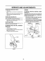
TO ADJUST
o
ENGINE "--PULLEY
BRAKE (See Fig. 26)
,,"LGCATOR
TABS
CLUTCHING
IDLER
Your tractor is equipped with an adjustable brake system
which is rnountedon the right side of the transaxle.
If tractor requires more than six (6) feet stopping distance
at high speed in highest gear, then brake must be adjusted_
°
Depressclutchibrake
°
Measure distance between brake operating arm and
nut "A" on brake rod°
°
If distance is other than 1-1/2", disengage parking
brake, loosen jam nut and turn nut "A" until distance
becomes 1-1/2". Retighten jam nut against nut 'WL
•
°
"" UPPER BELT
KEEPER
STATIONARY
IDLER
pedal and engage parking brake,
TRANSAXLE,._
PULLEY
, _'_
Engage parking brake and recheck distance_
Road testtractor for proper stopping distance as stated
above, Readjust if necessary. If stopping distance is
still greater than six (6) feet in highest gear', further
maintenance is necessary. Contact your nearest authorized service center/department.
Q
FIG. 27
22
CE AND ADJUSTMENTS
TO ADJUST
STEERING
TO START ENGINE WITH A WEAK BATTERY
See Fig. 29)
WHEEL ALIGNMENT
If steering wheel crossbars are not horizontal (left to right)
when wheels are positioned straightforward, remove steering wheel and reassemble per instructions in the Assembly
section of this manual.
ateexplosivegases. Keepsparks, ftame
and
smokingLead-acid
materialsbatteries
away from
batCAUTION:
generteries. Always wear eye protection
when around batteries.
FRONT WHEEL TOE-IN/CAMBER
The front wheel toe_in and camber are not adjustable on
your tractor, If damage has occurred to affect the front
wheel toe-in or camber, contact your nearest authorized
service center!departmenL
,,,,, ,,,,,,,,
'TO REMOVE WHEEL FOR REPAIRS
(See Fig. 28)
•
=
Block up axle securely.
Remove axle cover, retaining ring and washers to altow
wheel removal (rear wheel contains a square key _Do
not lose).
°
Repair tire and reassemble.
°
On rear wheels only: align grooves in rear wheel hub
and axle. Insert square key.
.
Replace washers and snap retaining ring securely in
axle groove.
•
Replace axle cover°
,, ,,,,,
If your battery is too weak to start the engine, it should be
recharged°
If "jumper cables" are used for emergency
starting, follow this procedure:
IMPORTANT:
YOUR UNIT IS EQUIPPED
WITH A 12
VOLT NEGATIVE GROUNDED
SYSTEM,
THE OTHER
VEHICLE
MUST ALSO BE A 12 VOLT NEGATIVE
GROUNDED SYSTEM.
DO NOT USE YOUR TRACTOR
BATTERY TO START OTHER VEHICLES°
TO ATTACH JUMPER CABLES .
Connect each end of the RED cable to the POSITIVE
(+) terminal of each battery, taking care not to short
against chassis.
•
Connect one end of the BLACK cable to the NEGATIVE (-) terminal of fully charged battery°
°
Connect the other end of the BLACK cable to good
CHASSIS GROUND, away from fuel tank and battery°
TO REMOVE CABLES, REVERSE ORDER •
BLACK cable first from chassis and then from the fully
charged battery.
°
RED cable last from both batteries.
WASHERS
POSITIVE TERMINAL
RETAINING
RING
Q
NEGATIVE TERMINAL
I
AXLE COVER
%_
SQUARE
KEY
(REAR WHEEL ONLY)
FIG. 28
CABLES
CHARGED
BATTERY
POSITIVE
TERMINAL
NEGATIVE
FIG. 29
23
TERMINAL
E
AND ADJUSTMENTS
ii H=,=,
TO REPLACE
HEADLIGHT
BULB
H,i,
_lllllt
....................
ENGINE
=
•
Raise hood..
Pull bulb holder' out of the hole in the backside of the
grill.
TO ADJUST THROTTLE
(See Fig. 31)
•
Replace bulb in holder and push bulb holder securely
back into the hole in the backside of the grill°
Close hood.
The throttle control has been preset at the factory and
adjustment should not be necessary_ Check adjustment as
described below before loosening cable° If adjustment is
necessary, proceed as follows:
°
INTERLOCKS
AND RELAYS
Loose or damaged wiring may cause your tractor to run
poorly, stop running, or prevent it from starting°
°
Check wiring. See electrical wiring diagram in the
Repair Parts section of this manual,.
TO REPLACE
FUSE
CONTROL
CABLE
°
With engine not running, move throttle control lever
from slow (-=_) to choke (N) position. Slowiy move
lever from choke (N) to fast (,_,) position.
•
Check that holes'A" in governor control lever'and hole
in governor plate line-up, if holes "A" are not aligned,
loosen clamp screw and move throttle cable until holes
are aligned. Tighten clamp screw securely._
Replace with 30 amp automotive-type plug-in fuse. The
fuse holder'is located behind the dash,
GOVERNOR
CONTROL LEVER
GOVERNOR
CONTROL PLATE
TO REMOVE HOOD AND GRILL ASSEMBLY
(See Fig. 30)
-
Raise hood..
,
°
Unsnap headlight wire connector.
Stand in front of tractor'. Grasp hood at sides, tilt toward
engine and lift off of tractor°
•
To replace, reverse above procedures.
HOLES "A"
CLAMP
SCREW
HOOD
FIG. 31
HEADLIGHT
WIRE
CONNECTOR
FIG. 30
24
THROTTLE
CABLE
SERVICE AND ADJU
IIIIIII1_111111
TO ADJUST
CARBURETOR
I
I
IIII
I
L
L
I
II
LL
IIIILI
(See Fig. 32)
ILL
I
IIIIIIIII
I
I
IIIIIII11111111111111111
Illlllllll'llll
I1111111
IILIIIII
LII
IIIIIII
I
II
ACCELERATION TEST-
The carburetor has been preset at the factory and adjustment should not be necessary° However, minor adjustment may be required to compensatefordifferences infuel,
temperature, altitude or load, if the carburetor does need
adjustment, proceed as follows:
°
In general, turning idle mixture valve in (clockwise) decreases the supply offuel to the engine givinga leaner fuel/
air mixture. Turning the idle mixture valve out (counterclockwise) increases the supply offuel to the engine giving
a richer fueVair mixture_
High speed stop is factory adjusted.
Do not adjust damage may result,.
IMPORTANT;
NEVER TAMPER WITH THE ENGINE
GOVERNOR, WHICH IS FACTORY SET FOR PROPER
ENGINE SPEED, OVERSPEEDING
THE ENGINEABOVE
THE FACTORY
HIGH
SPEED
SETTING
CAN BE
DANGEROUS.
IF YOU THINK THE ENGINE-GOVERNED
HIGH SPEED NEEDS ADJUSTING,
CONTACT
YOUR
NEAREST
AUTHORIZED
SERVICE
CENTER/
DEPARTMENT, WHICH HAS PROPER EQUIPMENTAND
EXPERIENCE
TO
MAKE
ANY
NECESSARY
ADJUSTMENTS.
IMPORTANT:
DAMAGE TO THE NEEDLE VALVE AND
THE SEAT IN CARBURETOR
MAY RESULT IF SCREW IS
TURNED 1N TOO TIGHT.
PRELIMINARY SETTING •
Aircleanerassembly must be assembled to the carburetor when making carburetor adjustments.
Be sure the throttle control cable is adjusted properly
(see above).
I
Move throttle control leverfrom slow
position, if engine hesitates or dies,
valve out (counterclockwise)
1/8 turn.
continue to adjust, if necessary, until
ates smoothly.
THROTTLE
LEVER
IDLE SPEED
SCREW
°
With engine off turn idle mixture valve in (clockwise)
closing it finger tight and then turn out (counterclockwise) 1 full turn_
FINAL SETTING °
Start engine and allow to warm forfive minutes. Make
final adjustments with engine running and shift/motion
control lever in neutral (N) position,,
o
Move throttle control lever to slow (,q_) position. With
finger, rotate and hold throttle lever against idlespeed
screw. Tum idle speed screw to attain 1750 RPMo
o
While still holding throttle lever against idle speed
screw, turn idle mixture valve in (clockwise) until engine begins to die and then turn out (counterclockwise)
until engine runs rough,, Turn valve to a point midway
between those two positions. Release throttle lever°
IDLE MIXTURE
VALVE
FIG. 32
25
(,=_) to fast (,_)
turn idle mixture
Repeattest and
engine acceler-
ENGINE
Immediately prepare your tractor for' storage at the end of
the season or if the tractor will not be used for 30 days or
more..
..........
:...........
..........
.
i iiiii
i ii
FUEL SYSTEM
,: ...........
IMPORTANT:
tT 1S IMPORTANT
TO PREVENT GUM
DEPOSITS
FROM FORMING
IN ESSENTIAL
FUEL
SYSTEM PARTS SUCH AS CARBURETOR, FUEL FILTER,
FUEL HOSE, OR TANK DURING STORAGE.
ALSO,
EXPERIENCE
INDICATES THAT ALCOHOL BLENDED
FUELS (CALLED GASOHOL OR USING ETHANOL OR
METHANOL) CAN ATTRACT MOISTURE WHICH LEADS
TO SEPARATION AND FORMATION OF ACIDS DURING
STORAGE.
ACIDIC GAS CAN DAMAGE
THE FUEL
SYSTEM OF AN ENGINE WHILE IN STORAGE.
gasoline in the tank inside a building
where fumes may reach an open flame
or spark. Allow the engine to cool
before storing in any enclosure.
i iiii1,1 i
ilUl
ii
...................
:.................................
TRACTOR
Remove mower from tractor for' winter storage.. When
mower' is to be stored for' a period of time, clean it thoroughly, remove all dirt, grease, leaves, etco Store in a
clean, dry area.
•
•
o
o
Clean entire tractor (See"CLEANING"inthe Customer
Responsibilities section of this manual)°
Inspect and replace belts, if necessary (See belt rep acement instructionsinthe Service and Adjustments
section of this manual).
Lubricate as shown in the Customer Responsibilities
section of this manual
To help prevent corrosion and power leakage during
{ong periods of storage, battery cables should be
disconnected and battery cleaned thoroughly (see %O
CLEAN BATTERY AND TERMINALS in the Customer' Responsibilit{es section of this rnanual).
°
=
Never use engine or carburetor cleaner products inthe
fuel tank or permanent damage may occur.
Use fresh fuel next season..
ENGINE OIL
Drain oil (with engine warm) and replace with clean engine
oil. (See "ENGINE" in the Customer Responsibilities
section of this manual)..
BATTERY
o
Start the engine and let it run until the fuel lines and
carburetor are empty.
NOTE: Fuel stabilizer is an acceptable alternative in
minimizing the formation of fuel gum deposits during storage.. Add stabilizer to gasofine in fuel tank or storage
container_. Always follow the mix ratio found on stabilizer
container'. Run engine at least 10 minutes after adding
stabilizer to atlowthe stabilizer'to reachthe carburetor'. Do
not drain the gas tank and carburetor if using fuel stabilizer.
Touch up at! rusted or chipped paint surfaces; sand
lightly before painting.
Fully charge the battery for' storage.
After a period of time in storage, battery may require
recharging.
Drain the fuel tank.
°
-
Be sure that all nuts, bolts and screws are securely
fastened. Inspect moving parts fordamage, breakage
and wear. Replace if necessary°
o
•
°
CYLINDERS
After cleaning, leave cables disconnected and place
cables where they cannot come in contact with batter,]
terminals.
•
Remove spark plug(s),
-
Pour one ounce of oil through spark plug hole(s) into
cylinder(s).
•
Turn ignitionkeyto"START" position for a few seconds
to distribute oil.
°
Replace with new spark plug(s).
OTHER
o
Be sure battery drain tube is securely attached.
°
Do not store gasoline from one season to another_
°
If battery is removed from tractor for storage, do not
store battery directly on concrete or damp surfaces.
°
Replace your gasoline can if your can starts to rust.
Rust and/or dirt in your gasoline will cause problems.
°
If possible, store your tractor indoors and cover it to
give protection from dust and dirt°
-
Cover yourtractor with a suitable protective covetthat
does not retain moisture. Do not use plastic. Plastic
cannot breathe which allows condensation to form and
will cause your tractor to rust.
IMPORTANT: NEVER COVER TRACTOR WHILE ENGINE
AND EXHAOST AREAS ARE STILL WARM.
26
TROUBLESHOOTING
PROBLEM
Wtl! not start
CORRECTION
CAUSE
1,
2
3,
4,
5,
6,,
7,,
1.. Out of fuel,
2,,
3,
4.,
5.
6
7
POINTS
Engine not "CHOKED" properly.,
Engine flooded
Bad spark plug
Dirty ak filter,.
Dirty fuel filter.
Water in fuel
8
9,
10,
8
Loose or damaged wiring.
9, Carburetor out of adjustment
10,, Engine valves out of adjustment
Fill fuel tank.
See "TO START ENGINE" in Operation section,,
Watt several minutes before attempting to start.
Replace spark plug,
Clean!replace air filter
Replace fuel filter
Drain fuel tank and carburetor, refill tank with fresh
gasoline and replace fuel filter,
Check all wiring
Contact an authorized service facility,
Contact an authorized service facility,
ii
i i ii/
Ull]l
Herd to start
1., Dirty atr filter,,
2, Bad spark plug.
3, Weak or dead battery,
4
Dirty fuel filter.
5
Stale or dirty fuel
6
Loose or damaged wiring,
7o Carburetor out of adjustmenL
8, Engine valves out of adjustment.
1,
2
3,
4,
5,
6
7,
8
Engine will not turn over
1,
2,
3,
4,
5,
6
7_
8,
9.,
1,. Depress clutch/brake pedal,
2. Disengage attachment clutch,
3, Recharge or replace battery
4, Replace fuse,
5, Clean battery terminals
6, Check all wiring,
7., Check/replace ignition switch,.
8o Check/replace solenoid or starter.,
9, Contact an authorized service facility
Clutch/brake pedal not depressed
Attachment clutch is engaged.
Weak or dead battery,
Blown fuse
Corroded battery terminals
Loose ordamaged wfdng,
Faulty ignition switch.
Faulty solenoid or starter
Faulty operator presence swftch{es),
i
111 i11
1
2
3,
4
Weakordead battery_
Corroded battery terminals
Loose or damaged widng.,
Faulty solenoid or starter.
1,
2,
3,
4
Loss of power
1,
2.
3
4
5
6,
7,
8,
9.
Cutting too much grass/leo fast,
Throttle in "CHOKE" posifion
Build-up of grass, leaves and trash under mower_
Dirty afr filter.
Low oil level/dirty oil
Faulty spark plug.,
Dirty fuel filter,
Stale or dirty fuel
Water In fuel
1.,
2,
3o
4
5
6,
7.
8,
9,
Excessiv_ vibratton
%
2.
3,
uiiiii
Clean!replace air filter.,
Replace spark plug.
Recharge or replace battery.
Replace fuel filter
Drain fuel tank and refill with fresh gasoline.
Check all wtdng,
Contact an authorized service facility°
Contact an aulhodzed service facility.
iiiiiiii
Engine clicks but will not
start
10.,
1 !.,
12
13_
14.
I5,
i
Spark plug wire loose,
Dirty engine air scraen/lins,
Dirty/clogged muffler,
Loose or damaged wiring,,
Carburetor out of adjustment,
Engine valves out of adjustment
Set in "Higher Cut" position/reduce speed.,
Adjust throttle control
Clean underside of mower housing
Clean/replace air fitler_
Check oil level/change oil,
Clean and regap or change spark plug,
Replace fuel filter,
Drain fuel tank and refill with fresh gasolfne,,
Drain |uel tank and carburetor, refill tank wtth fresh
gasofine and replace fuel filter,
t0., Connect and tighten spark plug wire,,
tl,
Clean engine air screen/fins
12
Clean/replace muffler
13, Check a!l wiring
14.. Contact an authorized service facility
15, Contact an authorized service facility
1
2,
3.,
Worn, b_nt or loo_a btada
Bent blade mandrel
Loose/damaged part(s),
27
Recharge or replace battery,
Clean battery terminals,
Check all wiring
Check/replace solenoid or starter.
Replace blade, Tighten blade bolt
Replace blade mandrel,
Tighten toose part(s),. Replace damaged parts.
PROBLEM
CAUSE
Engine continues to run
i I,
when operator leaves seat
with attachment clutch
engaged
.............................
ill
CORRECTION
Faulty operator-safety presence control system
.......................
,/`'_
I,
Check widng, switches and connections,_ tf not
corrected, contact an authorized service facility.
j ill ii
Poor cut - uneven
1.
2
3,
4.
5,
Worn, bent or loose blade_
Mower deck not level,
Buildup of grass, leaves, and trash under mower_
Bent blade mandrel,
Clogged mower deck vent holes from buildup of
grass, leaves, and trash around mandrels,
1,
2
3,
4
5,
Replace b_ade_,Tighten blade bolt
Level mower deck,
CIean underside of mower housing
Repiace blade mandrel
Clean around mandrels to open vent holes,
Mower blades will not
rotate
1,
2,.
3.
4.
Obstruction in clutch mechanism.
WomJdamaged mower ddvs beit,=
Frozen ]dter pulley,,
Frozen blade mandrel.
1,
2,
3.
4
Remove
Replace
Replace
Replace
Poor grass discharge
1.
2,
3.
4,,
Engine speed too slow,
Travel speed too fast,
Wet grass°
Mower deck not level.
1,
2,
3,
4,,
Place throttle control tn "FAST" position
Shift to slower speed.
Allow grass to dry before mowing.
Level mower deck.
5.
6.
7.
8,
Lowluneven tire air pressure
Worn, bent or loose blade
Buildup of grass, leaves and trash under mower
Mower ddve belt worn
9, Biades Improperly Installed,
10.. Improper blades used,
11.. Clogged mower deck vent holes from buildup of
grass, leaves, and trash around mandrals,.
5,
6_
7,
8
9,
10,
11,
obstruction
mower drive belt,,
idler pulley.
blade mandrel,
Check fires for proper air pressure.
Rep]acetsharpen blade. Tighten blade bolt,
Clean underside of mower housing.
Replace mower ddve belt,.
Relnstafl blades sharp edge down.
Replace with blades listed tn this manual
Clean around mandrels to open vent holes,,
HeadUght{s) not working
(if so equipped)
1
2.
3.
4,
5.
Switch is "OFF,.
Bulb(s) burned out
Faulty light switch.
Loose or damaged wlrlng,
Blown fuse,,
1
2,.
3,
4,.
5,
"rum switch "ON"_
Replace bulb(s)
Check/replace light switch,_
Check wtdng and connections,
Replace fuse
Battery will not charge
I,,
2,
3,
4,
Bad battery cel[(s)_
Poor cable connections_
Faulty regulator (if so equipped),.
Faulty alternator.
1.
2.
3
4,.
Replace battery_
Check/clean atl connections
RepEace regulator,,
Replace alternator,,
Engine "backfires"
when turning engine
"OFF"
Engine throttle control not set at "SLOW"
position for 30 seconds before stopping englne,_
28
Move throfl,le control to "SLOW" position and allow
to {die for 30 seconds before stopping engine,
15 HP 42" TRACTOR -- MODEL NUMBER 917.257641
SCHEMATIC
i
BATTERY
t
,
RED
FUSE 30 AMP.
I
0,
=
I
STARTER
I
WHITE
,
BLACK
.....
CLUTCH/ BRAKE
RED
J
SOLENOID
SEAT SWITCH
(NOT OCCUPIED)
__f_l l
IGNITIO_
SWITC
1
BLACK
i
.......
"!
I
4-O Q
ATT'MENTCLUTCH
(CLUTCHOFF)
S
I-
GROUNDING
CONNECTOR
1
BLACK
SPARK
PLUG
UNIT
IGNITION
(_
t
I
t
!
BLUE
AFTER FIRE SOLENOID
CHARGING
2B VOLTS AO MIN, @ 3600 RPM
(CHARGING SYSTIFJ_ DISCONNECTED)
SYS'"fEM OUTPUT
RED
ORANGE
!
I
1
I
I
|
BROWN
HEADLIGHT
SWITCH (OFF)
IGNITION SWITCH
POSITION
,L
CIRCUIT
OFF .............
! + G
ON
B+ L
START
B+S + L
O
NON-REMOVABLE
CONNECTIONS
WIRING INSULATED CLIPS
NOTE: IF WIRING INSULATED
CLIPS WERE REMOVED FOR
SERVICING OF UNIT, THEY
SHOULD BE REPLACED TO
PROPERLY SECURE YOUR
WIRING i
---O--
REMOVABLE
CONNECTIONS
29
NOTE
YOUR TRACTOR IS EQUIPPED WITH
A SPECIAL ALTERNATOR SYSTEM.
/-)
THE LIGHTS ARE NOT CONNECTED
TO THE BATTERY, BUT HAVE THEIR
OWN ELECTRICAL SOURCE.
BECAUSE OF THIS, THE BRIGHTNESS
OF THE LIGHT8 WILL CHANGE WITH
ENGINE SPEED. AT IDLE THE LIGHTS
WILL DIM. AS THE ENGINE IS
SPEEDED UP, THE LIGHTS WILL
BECOME THEIR BRIGHTEST,
D
REPAIR PARTS
15 HP 42" TRACTOR
- - MODEL
NUMBER
917.257641
ELECTRICAL
22
41
36 38
35
39
I
1
i
8
/
!
/
3
1
/
/
\
1
/
1
\
\
\
I
l
I
i
2
I
I
I
i
I
I
I
3O
REPAIR PARTS
15 HP 42" TRACTOR
- - MODEL
NUMBER
917,257641
ELECTRICAL
KEY
NO.
1
PART
NO.
121265X
2
3
4
5
6
7
8
9
19
20
21
74760412
STD551025
STD551125
121264X
STD541025
109238)(
129965
109596X
STD551125
73350400
136850
22
23
24
25
26
2B
29
30
3t
32
33
34
35
36
37
38
39
40
41
42
43
44
70
4152J
STD551225
4799J
132202
108824X
4207J
121305X
140399
t 40400
t41226
140403
110712X
I08236X
STD601005
104445X
!40336
109553X
140414
71110408
13t563
138406
73640400
t40422
DESCRIPTION
Battery, 12 Volt, 25 Amp
1/4-20 UNC x 1/2
Bolt, Hex Head 1/4-20 unc x 3/4
Washer
Washer
Caps, Battery
Nut
Tube, Plastic, 12"
Box, Battery
Clamp, Hose
Washer, Lock
Nut, Hex, Jam 1/4-20 UNC
Harness, Light Socket
(Includes Key # 33)
Bulb, Light
Washer
Cable, Battery, 6 Gauge, Red, 11"
Cable, Battery, 6 Gauge, Red, 43"
Fuse, 30 Amp
Cable, Ground, 6 Gauge, Black, 12"
Switch, Piunger
Switch, Ignition
Nut, Ignition
Cover, Key Switch
Key, Ignition
Switch, Light
Bracket, Clutch Switch
Screw
Switch, Interlock, Clutch, 2 Terminal
Bracket, Interlock Switch
Switch, Interlock, Clutch, 4 Terminal
Harness, Ignition
Bolt, Hex Head, Fin.
Cover, Terminal, Red
Solenoid
Nut
Harness Engine B&S
NOTE: All component dimensions given in U,.S_inches
1 inch = 25.4 mm
31
REPAIR PARTS
15 HP 42" TRACTOR - .. MODEL NUMBER 917.257641
CHASSIS AND ENCLOSURES
A
B
lO
C
D
E
F
G
!
,J
K
L
M
P
Q
"I
28
I
21
1t
17
37
3O
13
GJ
31
32
REPAIR PARTS
15 HP 42" TRACTOR
- - MODEL
NUMBER
917.257641
CHASSIS AND ENCLOSURES
KEY
NO.
PART
NO.
1 14O341
2 I40356
3 17490612
6 140169
7 17490612
8 2751R
9 140637X013
10 5479J
11 122795X
12 121794)(
13 126276X
14 1749O608
15 74180512
16 STD54t431
17 I31445X459
18 !26938X
19 17411310
21 122933X
22 124479X
24 STD523707
25 19131312
26 STD541437
27 17490608
28 14O137
29 124029X
3O 140001X459
31 136619
32 17490612
33 105465X459
34 105464X459
35 STD533707
36 STD541437
37 i05466X
38 134774
39 134775
40 STD533710
5O STD541437
51 19131216
53 72140608
54 74760614
58 1105O6OO
DESCRIPTION
Chassis Assembly
Drawbar
Screw, Thd. Rollo 3/8-16 x 3/4
Saddle
Screw, Thd. Roll. 3/8-16 x 3/4
Clip,Line Fuel
Dash
Plug, Button
Panel, Dash, L,H.
Cover, Access
Panel, Dash, R.H.
Screw Thdrol 3/8-16 x 1/2
Screw, Machine, Truss Head
5/16-I8 UNC x 3/4
Nut
Hood Assembly
Bumper, Hood
Screw, Hex Wsh #13-16 Hi-Lo x 5/8
Rivet, Ratchet, Nylon
Washer, Nylon 28 x .75 x o19
Bolt
Washer 13/32 x 13/16 x 12 Gauge
Nut
Screw, Thdrol 3/8-16 x t/2
Grill
Lens, Headlight Bar, Clear
Fender
Bracket, Fender
Screw, Thdrol 3/8-16 x 3/4
Footrest, L,.Ho
Footrest, R.H.
Bolt
Nut
Pad, Footrest, Ribbed
Pivot Bracket Assembly, L°Ho
Pivot Bracket Assembly, Roll.
Bolt, Carriage 3t8-16 x 1
Nut
Washer 13/32 x 3/4 x 16 Gauge
Bolt, Carriage 3/8-16 x 3/4
Bolt, Hex Head 3/8-16 x 7/8
Washer, Lock, External Tooth
NOTE: All component dimensions given in U.S. inches
1 inch = 25.4 mm
33
REPAIR PARTS
15 HP 42" TRACTOR - - MODEL NUMBER 917,257641
DRIVE
57
,69
=
72
84
.66
64
17
19
33
6
62
35
36
34
95
1
34
REPAIR PARTS
15 HP 42" TRACTOR
- - MODEL
NUMBER
917.257641
DRIVE
KEY
NO,
PART
NO.
137363
2
3
4
5
6
8
10
11
12
13
110422X
123666X
12000028
t2t520X
'174905!2
141003
76020416
105701 X
19151216
7 t O40412
14
15
16
17
18
t9
20
21
22
23
24
25
26
27
28
29
3O
31
32
33
34
35
36
37
38
39
4O
41
42
43
44
45
46
STD551 t25
74780544
STD54143I
t21520X
STD523707
STD541437
17490512
106933X
130804
STD54t437
STD541237
106688X
STD551037
STD561210
140448
124236X
130807
127275X
STD523107
STD541431
122424X
120183X
STD551062
STD571810
123674X
STD523727
4470J
109070X
19131312
STD541437
105706X
110812X
12000039
DESCRIPTION
Transaxle, Dana, 6 Speed,
Model Number 4360-48
Spring, Extension, Brake
Pulley, Transaxle
Ring, Retainer
Strap, Torque, R.H.
Screw, Thdo, Roll 5/16-18 x 3/4
Lever, Shift
Pin, Cotter
Washer, Shift Plate
Washer 15/32 x 3/4 x 16 Gauge
Bolt, Hex Head, Fin.
1/4-28 UNF x 3/4 Grade 8
Washer
Bolt, Hex Head 5/16_18 x 2-3/4
Nut, Crownlock 5/16_18 UNC
Strap, Torque L_H_
Bolt
Nut
Screw, Thd.., Roll. 3/8-16 x 3/4
Knob
Rod, Brake
Locknut
Nut
Spring, Brake Rod
Washer
Pin
Rod, Parking Brake
Cap, Parking Brake, Red
Bracket, Transaxle
Keeper, Belt, L.H.
Bolt
Nut
Shaft Assembly, Foot Pedal
Bearing, Nylon
Washer
Roll Pin
Pulley, Idler, Flat
Bolt
Spacer, Split .395 x °59
Keeper, Belt, Retainer
Washer 13/32 x 13/t6 x 12 Gauge
Nut
Beating, Nylon
Washer, Hardened
Ring, Klip
KEY
NO.
PART
NO.
47
48
49
50
51
52
53
54
55
56
57
58
59
60
61
62
63
64
127783
123789X
123205X
STD523715
STD541437
STD551037
105710X
STD561210
105709X
STD561210
130801
127274X
140312
19131312
17490612
8883R
t40186
71170764
65
66
67
68
69
70
71
72
73
74
75
76
77
78
80
81
82
83
84
85
86
87
88
89
90
95
100
STD551143
129921
STD523710
19131312
STD541437
134683
STD523710
19132012
STD541437
109502X
121749X
STD581075
123583X
121748X
131488
136932
123782X
!9171216
132182
73530400
71208
19212016
12000008
139964
124346X
17490612
19111216
DESCRIPTION
Pulley, Idler, V-Groove, Plastic
BeUcrank Assembly
Retainer, Belt
Bolt
Nut
Washer
Link, Clutch
Pin
Spring, Clutch Return
Pin
V-Belt, Ground Drive
Keeper, Belt, R_H.
Keeper, Belt, Center Span
Washer 13/32 x 13/16 x 12 Gauge
Screw, Thd., Roll 3/8-16 x 3/4
Cover, Pedal
Pulley, Engine
Bolt, HexHead, Fin.
7/16-20 x 4 Grade 5
Washer
Keeper, Belt, Engine, Loll..
Bolt
Washer 13/32 x 13/16 x 12 Gauge
Nut
Guide, Mower Drive Belt, R_H.
Bolt
Washer 13/32 x I-1/4 x I2 Gauge
Nut
Spacer, Split .80 x .94
Washer 25/32 x 1-I/4 x 16 Gauge
E-Ring
Key, Square 2.0 x.1845/.1865
Washer 25/32 x 1-5/8 x 16 Gauge
Arm, Shift
Shaft Assembly
Spring, Torsion
Washer 17/32 x 3/4 x t6 Gauge
Tie Rod
Nut, Nylock
Bushing, Pivot
Washer
E-Ring
Console, Shift, 6 Speed, N/Ignition
Nut, Self-Threading, Washer Hd t/4
Screw, Thd., Roll. 318-16 x 3/4
Washer 11/32x3/4x16Ga.
NOTE: All component dimensions given in UoS.inches
1 inch = 25°4 mm
35
REPAIR PARTS
15 HP 42" TRACTOR
STEERING
- - MODEL
NUMBER
917.257641
ASSEMBLY
39
__41
/
I
I
t
1
47
14
46
33
16
32
43
34
I
10
36
35
REPAIR PARTS
15 HP 42" TRACTOR
STEERING
- - MODEL
NUMBER
917.257641
ASSEMBLY
KEY
NO.
PART
NO,
t '139768
2 142033
3 135227
4 135228
5 6266H
6 121748X
7 19272016
8 12000029
9 3366R
10 130468
11 STD551137
'12 73610600
13 110436X
14 74011056
!5 73901000
16 132624
17 132614
18 57079
19 124035X
20 126684X
21 STD551125
22 71070410
23
24
25
26
27
28
29
30
31
32
33
34
35
36
37
38
39
40
41
42
43
44
45
46
47
127501
109816X
124036X
12000029
136874
6266H
17490612
STD551137
73610600
130465
126847X
19131416
STD561210
132196
STD611005
139769
19133808
STD541537
104820X
124417X
121749X
12t748X
12O00029
121232X
6855M
DESCRIPTION
Steering Wheel
Front Axle Assembly
Spindle Assembly, L.Ho
Spindle Assembly, RH.
Bearing, Race, Thrust, Hardened
Washer 25/32 x 1-5/8 x 16 Gatlge
Washer 27/32 x 1-1/4 x 16 Gauge
Ring, Klip
Bearing, Steering Column
Link, Drag
Washer, Lock
Nut, Hex, Fin. 3/8-24 UNF
Spacer, Bearing, Front Axle
Bolt, Hex Head 5/8-11 UNC x 3-t/2
Nut, Lock, Flange 5/8-11 UNC
Pin, Axle 5/8 x 1.55tl °54
Shaft Assembly, Steering
Washer, Thrust .515 x °750 x .033
Support, Shaft
Washer, Shim 1/4 x 5/8 x .062
Washer
Screw, Hex Socket Head
1/4-20 x 5/8
Pittman Shaft Assembly
Nyliner, Snap-ln
Bracket, Steering
Ring, Klip
Gear, Sector
Bearing, Race, Thrust, Hardened
Screw, Thd., Roll. 3/8-16 x 3/4
Washer, Lock
Nut, Hex, Finn 3/8-24 UNF
Rod, Tie
Bushing, Link, Drag
Washer 13/32 x 7/8 x 16 Gauge
Pin
Bushing, Steering
Screw
Insert, Steering Wheel
Washer 13/32 x 2-3/8 x 8 Gauge
Gripco Nut
Adaptor, Steering Wheel
Boot, Steering Shaft
Washer 25/32 x 1-1/4 x 16 Gauge
Washer 25/32 x 1-5/8 x 16 Gauge
Ring, Klip
Cap, Spindle
Fitting, Grease
NOTE: All component dimensions given in U.S. inches
1 inch = 25.4 mm
37
REPAIR PARTS
15 HP 42" TRACTOR
- - MODEL
NUMBER
917.257641
SEAT ASSEMBLY
10
21
,'
22
4
12
KEY
NO.
PART
NO.
1
2
3
4
5
6
7
8
9
10
12
13
14
140123
140551
STD523707
19131610
140407
STD541437
124t81X
17490616
Seat
Bracket, Pivot, Seat
Bolt
Washer 13/32 x I x 10 Gauge
Clip, Push-ln ..375 x .250
Nut
Spring, Seat
Screw, Thd,, Roll. 3/8-16 x 1
19131014
Weaher
140552
1,21246X
121248X
72050411
Pan, Seat
Bracket, Switch Mounting
Bushing, Snap
Bolt, Carriage 1/4-20 x 1-3/8
DESCRIPTION
18132
× 1 x 14 Gaugo
KEY
NO.
PART
NO.
15
!6
17
21
22
23
134300
121250X
123976X
139888
STD541431
74780814
24
26
26
19171912
127O18X
STD551150
DESCRIPTION
Spacer, Split .28 x _88
Spring
Locknut, Flange 1/4 Grade 5
Bolt, Shoulder 5/16-18 UNC
Nut
Bolt, Hex Head, Fin.
1/2-13 x 7/8 Grade 5
Washer 17/32 x 1-3/16 x 12 Gauge
Bolt, _houlder
E;116-18
x, 62
Washer, Lock
NOTE: All component dimensions given in U.S. inches
1 inch = 25.4 mm
38
REPAIR PARTS
15 HP 42" TRACTOR
- - MODEL
NUMBER
917.257641
DECALS
9
6
13
3
15
7
7
15
4
16
t0
19
5
\
11
8
12
13
21
1
14
KEY
NO.
1
2
3
4
5
6
7
8
9
10
PART
NO.
138955
14!130
138137
128382
132674
133644
142235
133178
128314
137537
WHEELS
KEY
NO.
DESCRIPTION
Decal,
Decal,
Decal,
Decal,
Decal,
Decal,
Decal,
Decal,
Decal,
Decal,
Operating Instruction
B&S Diamond IC/Gold OHV
Hood, LT4000, RoHo
Hood, LT4000, LoH,,
Gdll, LT4000
Customer Maintenance
Side Panel, IC Gold
Mower, 3 In One
Fender, Craftsman
Caution, English
11
12
13
14
15
!6
17
t9
21
PART
NO,
4900J
109199X
131473
136832
142234
140837
133179
131265
138836
1383t 1
i41989
141990
DESCRIPTION
Decal, ClutchtBrake, English
Decal, V-Belt DrLve Schematic
Decal, Chassis, 6 Speed/42"
Decal, V-Belt Schematic
Decal, Insert Hood 15HP OHV
Decal, Parking Brake Saddle
Decal, Mower QC System
Decal, Lightbox, Grill
Decal, Dash Lawn Tractor Sit
Decal, Lift Handle
Owner's Manual, English
Owner's Manual, Spanish
& TIRES
KEY
NO.
1
2
3
4
11
PART
NO.
59192
65139
106222X
59904
5
6
7
8
9
10
106732X427
278H
9040H
106108X427
106268X
7152J
11
104757X
DESCRIPTION
Valve Cap, Tire
Stem, Valve
Tire, Front
Tube, Front Tire
(Not Provided, Service Item Only)
Rim, Front
Fitting, Grease (Front Wheel Only)
Bearing, Flange (Front Wheel Only)
Rim, Rear
Tire, Rear
Tube, Rear Tire
(Not Provided, Service Item Only)
Cap, Axle
REPAIR PARTS
15 HP 42" TRACTOR--
MODEL
NUMBER
917.257641
ENGINE
1
27
D
25
36
F
32
38
37
_
34
29
1
OPTIONALspark
ArresterEQUIPMENT!
......
iii
III
III
iii
II I III
IIII
UI
. .....
30
B
D
E
F
G
H
I
22
_2
_26_1:6_35
_24
18
_1:1_17
20
19
4O
2!
REPAIR PARTS
15 HP 42" TRACTOR
- - MODEL
NUMBER
917.257641
ENGINE
KEY
NO.
PART
NO.
1
2
132759
17720410
3
141129
6
11
12
13
14
15
16
17
18
19
20
21
22
23
24
25
26
125593X
STD551131
71070512
137352
13280324
'13200300
STD551237
1749062O
'136718
105839X
105838X
STD551025
123650X
128953X
STD60t005
126842X
17030808
27
29
30
31
32
33
34
35
105037X
137180
127057X
109202X
123549X
123487X
124028X
17490412
36
37
38
19091416
137040
---
DESCRIPTION
Controt, Throttle
Screw, Hex Head, Thread Cutting
1/4-20 x 5/8
Engine, B&S, 15Hp Diamond Dual
Model Noo28N707, Type NO. 0121-0t
Gasket, Exhaust
Washer, Lock
Screw, Hex Cap Head 5/16-18 x 3/4
Muffler
Nipple, Pipe 3/8 NPT x 3
Elbow, Standard 90 °, 3/8-18 NPT
Washer
Screw, Thdo, Roll. 3/8-!6 x 1-1/4
Shield, Heat
Receptacle, t/4 Turn
Retainer, 1/4 Turn
Washer
Stud, 1/4 Turn
Shield, Heat
Screw
Shield, Heat, Hood
Screw, Spiderloc, Hex }-lead
#8 x 1/2 AB
Strip, Foam
Arrestor, Spark
Strip, Foam
Tank, Fuel
Cap Assembly, Fuel Tank, Vented
Clamp, Hose
BushIng, Snap, Fuel Line
Screw, Hex Washer Head, Thdo, Roll. 1/
4-20 x 3/4
Washer 9/32 x 7/8 x 16 Gauge
Line, Fuel
Plug, Oil Drain
(Order From Engine Manufacturer)
NOTE: All component dimensions given in U.S. inches
1 inch = 25.4 mm
41
REPAIR PARTS
15 HP 42" TRACTOR
- - MODEL
NUMBER
917.257641
MOWER LIFT
29
28
27
26
23
21
4 5
6
!
f
3O
3
\
6
13
G_-,..13
_J<"'13
2O
1
15
14
42
_
161718
2O
20
REPAIR PARTS
15 HP 42" TRACTOR
- - MODEL
NUMBER
917.257641
MOWER LIFT
KEY
NO.
PART
NO.
1
2
3
4
5
6
7
8
10
11
12
t3
14
15
16
17
18
136973
122507X
105767X
12000002
19211621
120183X
125631X
122365X
122512X
134619
135388
4939M
135563
127218
73350800
130171
73800800
19
20
21
22
23
24
25
26
27
28
29
30
130832
3146R
19151216
12000037
!10807X
19131016
2876H
76020308
126971X
73350600
138057
1108t0X
DESCRIPTION
Lift Lever Inner Wire Assembly
Shaft Assembly, Lift
Pin, Groove
E-Ring
Washer 21/32 x I x 21 Gauge
Bearing, Nylon
Grip, Handle, Fluted
Button, Plunger, Red
Spring
Link, Lift, Loll.
Link, Lift, R.H..
Retainer Spring
Pin, Roll, SIotted 5/16 x 1.25
Link, Front
Nut, Hex, Jam i/2-13 UNC
Trunnion
Locknut, Hex, with Washer Insert
1/2-'13 UNC
Arm, Suspension, Rear
Retainer Spring
Washer 15/32 x 3/4 x 16 Gauge
Ring, Klip
Nut, Special
Washer 13/32 x 5/8 x 16 Gauge
Spring
Pin, Cotter 3/32 x 1/2
Rod, Adjust, Lift
Nut, Hex, Jam 3/8-16 UNC
Knob, Infinite Height Adjustment
Trunnion, Depth Stop
NOTE: All component dimensions given in UoS. inches
1 inch= 25A mm
43
REPAIR PARTS
15 HP 42" TRACTOR
42" MOWER
- - MODEL
NUMBER
917.257641
DECK
65
66
6B
<
,/
4O
3
38
76
33
42
74
32
31
47
19
21
22
23
84
24
25
26
16
28
29
44
27
REPAIR PARTS
15 HP 42" TRACTOR
- - MODEL
NUMBER
917.257641
42" MOWER DECK
KEY
NO.
PART
NO.
1
2
3
4
4A
5
6
7
8
9
10
11
12
13
138024
STD533107
138017
138440
132827
STD624008
130832
73800500
850857
STD551137
140296
134149
129895
137645
t4
15
16
17
18
19
20
21
22
23
24
25
26
27
28
29
30
31
32
33
34
35
36
37
38
39
128774
110485X
136929
721106t8
72140505
73800500
136888
STD541431
134753
t31267
105304X
123713X
110452X
130968
19111016
13!491
138776
129963
129861
137266
STD533717
133835
131494
19131612
133502
133503
40
41
42
43
44
45
STD541437
t33551
STD560907
t33504
140088
STD624003
KEY
NO.
DESCRIPTION
Mower Housing
Bolt
Bracket Assembly,Sway Bar, Front
Bracket Assembly, Sway Bar
Bolt, Shoulder
Retainer Spring
Arm, Suspension, Rear
Locknut 5/16-18
Bolt, Hex 3/8-24 x 1o25 Grade 8
Washer, Lock
Washer, Hardened
Blade, Mulching
Bearing, Ball
Shaft Assembly, Mandrel, Vented
(includes Key Number 6)
Housing, Mandrel, Vented
Bearing, Ball, Mandrel
Stripper, Vented Mower Deck
Bolt, Carriage 3/8-16 x 2-1/4
Bolt, Carriage 5116-18 x518
Locknut 5/16-18
Baffle, Vortex
Nut
Stiffener Bracket
Bracket, Deflector
Cap, Sleeve
Spring, Torsion, Deflector
Nut, Push
Shield, Deflector
Washer 11/32 x 518 x 16 Gauge
Rod, Hinge
Screw Thdrol Hex Head Zinc Mwr
Washer, Spacer
Pulley, Mandrel
Nut, Toplock, Flanged
Bolt
Fastner, Christmas Tree
Pulley, Idler, Flat
Washer t3/32 x 1 x 12 Gauge
Spacer, Idler Arm, Upper
Stiffner, Idler Arm, Upper,
Hardened
Nut
Rod, Pivot, with Nibs
Cotter Pin
Rod, Clutch, Secondary, with Nibs
Guard, Mandrel, L.H..
Retainer
PART
NO.
46 137729
47 t31335
48 133944
49 133940
50 131340
51 STD541410
52 139888
53 131845
54 133943
55 133844
56 122052X
57 127498
58 128759
59 140334
60 133550
61 131870
62 127847
63 121748X
64 12000029
65 128903
66 127845
67 106932X
68 130969
74 136420
75 71161010
76 19061216
77 STD551110
78 130758
79 2029J
80 137644
81 133957
83 73930600
84 74760512
85 73510500
86 72110504
87 132263
88 t32262
94 73350600
95 133205
- - 130794
--
138358
DESCRIPTION
Screw, Thdo Roll 1/4-20 x 5/8
Spring, Extension
Washer, Hardened
Roller Assembly, Cam Follower
Bolt, Shoulder #10-24 Grade 5
Locknut
Bolt, Shoulder 5/16_18 UNC
Arm Assembly, Pad, Brake
Washer, Hardened
Arm, Idler
Spacer, Retainer
Bushing, Large, Brass
Spring, Mower Clutch
Arm, Clutch, Primary
Rod, Clutch, Primary, with Nibs
Spring, Return
Arm, Clutch, Secondary
Washer 25/32 x 1-5/8 x 16 Gauge
Ring, Klip
Bolt, Shoulder 3/8-t 6 UNC x 1.44
Keeper, Spring
Knob, Round 3/8-16 UNC
V-Belt
Mulcher Cover
Screw
Washer #10
Washer, Lock
Latch Assembly, Bagger
Nut, Weld
Bolt, Shoulder
Wheel, Gauge
Nut, Centertock 3/8-16
Bolt, Hex Head 5/16-18 UNC x 3/4
Nut, Hex, Keps 5/16-18 UNC
Bolt, Carriage 5/16 UNC x 1/2
Bracket, Gauge, Wheel Loll.
Bracket, Gauge;Wheel R..H.
Nut, Hex Jam 3/8-16 Unc
Trunnion, Adj. 3/8.-16 x 1.30
Mandrel Assembly (Includes Key
Numbers 8-10, 12-15, 31 and 32)
Mower Deck, Complete (Standard
Deck, Does Not Include Mulching or
Gauge Wheel Components, Key
Nos. 74-88)
NOTE: All component dimensions given in U..S. inches
1 inch = 25°4 mm
45
REPAIR PARTS
15 HP 42" TRACTOR
DANA TRANSAXLE
- - MODEL
NUMBER
917.257641
- MODEL NUMBER 4360-48
22
19
31
26
27
32
33
14 35
36
1
t
13
37
I4
15
19
52
40
53
41
42
16
17
54
44
45
55
46
47
56
48
57
49
59
5O
55
5t
55
6O
46
19
REPAIR PARTS
15 HP 42" TRACTOR,
DANA TRANSAXLE
KEY PART
NO. NO.
1
2
138248
2274J
3
4
5
6
7
8
9
10
11
12
13
14
15
t6
17
18
19
20
21
22
23
24
25
26
27
28
29
30
31
32
33
34
35
36
37
38
134400
105904X
I05905X
138235
134399
134791
138241
2267J
134793
138240
120415X
2257J
138234
110078X
105909X
105910X
105911X
t38242
138246
138236
7381 O500
138243
2244J
105916X
120470X
110070X
108977X
109254)(
120405X
108980X
120406X
134796
105925X
2232J
108978X
!10079X
39
40
124639X
120472X
- MODEL
NUMBER
917.257641
- MODEL NUMBER 4360-48
KEY PART
NO. NO.
DESCRIPTION
Housing, Upper
Screw, Self-Tapping, Large
1/4-20 x _734
Ball, Detent
Spring, Detent
Screw, Set
Kit, Shifter Assembly
Boot, Shifter
Screw, Tapping w/Sealer
Square Ring
Ring, Retaining
* Assembly, Kit, Shim 625 Shaft
Bearing, Flange
Washer, Plain °632 x 1.38 x .046
Key, Woodruff, #9
Assembly, Kit, Input Shaft
Pinion, Bevel, 14 Teeth
Ring, Retaining
Chain, 24 Pitches
Bearing, Flange
Gear, Spur, 14 Teeth
Collar, Clutch
Assembly, Kit, Clutch Keys
Locknut 5/16_24
Shaft, Intermediate
Key, Woodruff, #61
Ring, Retaining
Sprocket, 18 Teeth
Spacer
Gear, S _ur,37 Teeth
Gear, S _ur,35 Teeth
Gear, S )ur, 30 Teeth
Gear, S _ur,25 Teeth
Gear, S _ur, 22 Teeth
Gear, S _ur, 19 Teeth
Washer Plain °640 x 1.37 x ..06t
Washer. Plain .632 x 1.00 x ..026
Spacer .630 x 1.00 x .169
Assembly, Gear, Combination of
12 Teeth and 35 Teeth
Shaft, Idler
Spacer .635 x .875 x .755
41
42
43
44
45
46
47
48
49
50
51
52
53
54
55
56
57
58
59
60
61
62
63
64
65
66
67
105928X
110084X
134394
120473X
105933X
106151X
120407X
106589X
120408X
t05937X
2226J
134401
2264J
120474X
110081X
105941X
110071X
120952X
110082X
t20475X
138247
120961X
7294J
108989X
120953X
120954X
134799
68
69
70
7I
138244
108996X
120956X
106596X
72
73
120951X
120416X
*
**
DESCRIPTION
Sprocket, 9 Teeth
Gear, Bevel, 42 Teeth
* Assembly, Kit, Shim ,750 Shaft
Shaft, Drive
Gear, Spur, 12 Teeth
Gear, Spur, 15Teeth
Gear, Spur, 20Teeth
Gear, Spur, 25 Teeth
Gear, Spur, 28 Teeth
Gear, Spur, 31 Teeth
Washer, Plain .632 x to00 x .060
Washer, Neoprene
Washer, Plain ..758 x 1o25 x .031
Axle, L H..
Gear, Miter, 15 Teeth
Ring, Retaining
Gear, Spur, 32 Teeth
Shaft, Cross
Gear, Miter, 15 Teeth
Axle, Roll.
Housing, Lower
Puck, Friction
Disc, Brake
Spacer
Jaw, Brake
Pin, Dowel
Screw, Self-Tapping, Large
5/16-18 x 225
Lever, Actuating
Washer, Plain ,.321 x 1,00 x °055
Bracket, Anti-Rotation
Screw, Self-Tapping, Large
5/16-18 x 1.44
Puck, Friction
Grease
Use in combinations to maintain proper clearances
Order Key No. '15
NOTE: All component dimensions given in U.S. inches
1 inch = 25..4 mm
47
REPAIR PARTS
15 HP 42" TRACTOR
BRIGGS & STRATTON
- - MODEL
ENGINE - MODEL NUMBER
635
NUMBER
917.257641
28N707, TYPE NUMBER
0121-01
337
"A"REQUIRES SPECIAL TOOLS
TO INSTALL. SEE REPAIR
INSTRUCTION MANUAL.
7
52
45
1034
1029
294 _
1026
48
REPAIR PARTS
15 HP 42" TRACTOR
BRIGGS & STRATTON
127
138
106 987
- - MODEL
917.257641
ENGINE - MODEL NUMBER 28N707, TYPE NUMBER
95 117
634
51
0121-01
634B
.........
105
O
NUMBER
142
147
137
1033 VALVE OVERHAUL
121 CARBURETOR
OVERHAUL
KIT
H_....................
'27_
22
15
52
1
"_rREQUIRES SPECIALTOOLS
TO INSTALL, SEE REPAIR
INSTRUCTION MANUAL.
49
KIT
11111
iii
REPAIR PARTS
15 HP 42" TRACTOR
BRIGGS & STRATTON
- - MODEL
NUMBER
917.257641
ENGINE - MODEL NUMBER 28N707, TYPE NUMBER
20
523
.......
842
634A
5
2'4e'68
.....
868A
0121-01
467
284A
535
............
358QASKET
SEt..........
445
363
_524
°
138
137
_977 CARBURETOR
GASKET SET
668
224
I
304
305A_
455
37
1054
50
REPAIR PARTS
15 HP 42" TRACTOR
BRIGGS & STRATTON
- - MODEL
ENGINE - MODEL NUMBER
NUMBER
917.257641
28N707, TYPE NUMBER
0121-01
22
oo;
/
/
482
877
657
%
601
209
....
13ooli
..............................
801
311
513
310
544
Reference Number
Menufscturer
Briggs &
Stratton
12V
3O9
Motor&
Drive
3,!o,,,
; Thru Bolt
311
Brush
Assembty Assembly
Assembly
510
Starter
Drlve
Group
544
,, 801
ArmBture Drive End
iAssembly
Cap
!Assembly
802
803
Housing
End Cap
Assembly Assembly
Commutator
Housing
Length
_ 3-21/32"
* Includes #398003
#280104
#495877
#94268
**394805
94003
39_38 ......
;,4,_SeTe,*
Clutch Assembly (RefoNo, 513)
Gear
(Ref,, No_783)
Retainer and Pin (Ref_ No,,876)
Roll Pin
(RefoNo, 896)
**Uses
#94627
51
m
.......
_0_7_*
Screw-Hex, Head (Ref. Not 728)
REPAIR PARTS
15 HP 42" TRACTOR-BRIGGS & STRATTON
KEY PART
NO. NO.
1 496412
2 399265
3 391086
5 495858
7 272614
8 495735
9'27803
10 94621
1t 281246
12 271916
271997
271996
13 94728
15 94239
16 495162
94196
18 494238
20 291675
22 94624
23 492326
24
25
26
27
28
29
33
32
32A
34
35
37
4O
45
46
222698
495860
495977
495978
495979
495854
495852
495851
495855
260924
299691
391286
494504
49549O
495856
94695
94648
495857
262811
2245O2
224641
262411
494433
MODEL NUMBER 917.257641
ENGINE - MODEL NUMBER 28N707, TYPE NUMBER
KEY PART
NO. NO.
DESCRIPTION
Cylinder Assembly
Bearing, Cylinder
Seal, Oil
Head, Cylinder
Gasket, Cylinder Head
Breather Assembly
Gasket, Valve Cover
Screw, Sems
Tube, Breather
Gasket, Crankcase Cover, 1/64"
Gasket, Crankcase Cover, °005"
Gasket, Crankcase Cover', .009"
Screw, Cylinder Head
:
Plug, Oil Drain
Crankshaft
Timing Gear Key
Base, Engine
Seal, Oil
Screw, Sems, Base Mounting
Flywheel and Ring Gear Assembly,
Magneto
Key, Flywheel
Piston Assembly, Standard Size
Piston Assembly, .010" Oversize
Piston Assembly, .,020"Oversize
Piston Assembly, .030" Oversize
Ring Set, Piston, Standard Size
Ring Set, Piston, .010" Oversize
Ring Set, Piston, ..020"Oversize
Ring Set, Piston, .030" Oversize
Lock, Piston Pin
Pin Assy., Piston, Standard Size
Ptond_,sSsYe,
mPl_t
y 7_on0n05ctO}_e
" g rsize
Rod Assembly, Connecting,
.020" Undersize Crankpin Bore
Valve, Exhaust
Screw, Hex Washer Head, 1-57/64
Screw, Hex Washer' Head, 1-5/8
Valve, Intake
Spring, Valve
Guard, Flywheel
Retainer', Valve Spring
Tappet, Valve
Gear, Cam
51
272465
52
272569
53
75
78
95
98
104
105
106
108
117
118
121
123
125
127
130
t31
133
137
138
141
142
147
164
166
!71
187
188
94637
224O61
94626
94098
4958O0
231789
231855
231854
22454O
231858
495932
495799
94616
495935
192
20t
209
216
219
222
224
225
227
230
224539
494379
494381
281165
281164
495931
231859
231794
214053
94555
281051
393815
93535
492160
262767
260695
262766
490815
495611
94729
231058
493935
94742
0121-01
DESCRIPTION
Gasket, Carburetor
arburetor to Elbow)
asket, Carburetor
(Elbow to Cylinder')
Stud, Carburetor Mounting
Washer, Spring
Screw, Sems
Screw, Throttle
Screw, Idle Speed
Pin, Float Hinge
Valve Float
Seat, Inlet Valve
Valve, Choke
Jet, Needle Valve
Valve, Needle
Carburetor Overhaul Kit
Screw, Etbow Mounting
Carburetor Assembly
Plug, Welch (Sold in Kit Only)
Valve, Throttle
Shaft and Lever, Throttle
Float, Carburetor
Gasket, Float Bowl
Washer, Bowl
Shaft and Lever, Choke
Nozzle, Carburetor
Pilot, Jet
Elbow, Carburetor
Stud, Rocker' Arm
Nut, Air Cleaner Mounting
Line, Fuel (11" Long, Cut to Suit)
Screw, Hex Head, 3/4
Screw Assembly, Rocker Arm
Link, Governor
Spring, Governor
Link, Choke
Gear, Governor
Plate, Governor Control
Screw, Sems, Air Cleaner
Crank, Governor
Lever Assembly, Governor'
Washer, Governor Crank
NOTE: All component dimensions given in U.& inches
1 inch = 25,4 mm
52
REPAIR PARTS
15 HP 42" TRACTOR
BRIGGS & STRATTON
KEY PART
NO. NO.
232
238
240
265
284
284A
294
304
305
262785
262836
394358
221535
94326
94073
810068
496280
94513
305A
94734
306
307
333
334
337
346
356
358
363
383
423
445
455
467
468
474
482
523
524
525
535
537
552
562
592
601
611
614
615
618
634
634A
224696
94623
495859
93381
491055
93705
496070
495993
19203
89838
94073
493909
222561
493903
224948
393474
93621
495230
68838
496113
272403
281106
231597
92613
231082
93053
493496
93306
93307
262803
281168
491323
- - MODEL
ENGINE - MODEL NUMBER
NUMBER
28N707, TYPE NUMBER
KEY PART
NO. NO.
DESCRIPTION
Spring, Governor Link
Cap, Valve
Filter, Fuel (In Fuel Line)
Clamp, Casing
Screw, Hex Head
Screw, Hex Head
Screw, Set
Housing, Blower
Screw, Hex, Head,
Blower Housing Mounting
Screw, Hex Head,
Blower Housing Mounting
Shield, Cylinder
Screw, Cylinder Shield
Armature, Magneto
Screw, Sems, Armature Mounting
Plug, Spark
Screw, Hex Head
Wire Assembly
Gasket Set
Puller, Flywheel
Wrench, Spark Plug
Screw, Sems
Cartridge, Air Cleaner
Cup, Screen Mounting
Knob, Air Cleaner
Screen, Flush Rotating
Stator, Alternator
Screw, Sems
Cap and Dipstick, Oil Filler
SeaI, FilierTube
Tube, Oil Filter
Element, Filter
O-Ring, Air Cleaner
Bushing, Governor Crank
Bolt, Governor Lever
Nut, Hex
Ctamp, FuelPipe
Elbow, Fuel Pipe
Pin, Cotter
Retainer, E-Ring
Spring, Choke Return
Seal, Choke Shaft
Seal, Governor
917.257641
634B
635
646
657
668
718
726
281167
280872
224546
93496
280848
230192
392134
0121-01
DESCRIPTION
727 490324
741 262932
757 213998
758 399891
759 298909
761 94593
842 270920
847 496415
851 224110
868 494435
868A 272610
871 262835
872 281361
875 495862
877 393456
947 495739
965 94108
975 495933
977 494385
987 281166
1005 281355
1006 224413
1022 272475
1023 224552
1026 494432
495136
1029 224554
1033 495992
1034 495248
1044 94673
1054 270723
Washer, Throttle Shaft
Elbow, Spark Plug
Brace, Air Cteaner
Screw, Serns
Spacer
Pin, Dowel
Gear, Ring
(Includes Mounting Hardware)
Cover, Starter
Gear, Timing
Link, Counterweight
Counterweight Assembly
Pin, Counterweight
Screw, Counterweight
Seal, Oil Filler Cap
Fill Group, Oil
Terminal, Ignition Cable
Seal Assembly, Valve
Gasket, Valve
Bushing, Guide (Intake & Exhaust)
Cover, Air Cleaner
Body, Air Cleaner
Diode and Connector Assembly
Solenoid
Nut, Hex
Bowl Assembly, Carburetor
Carburetor Gasket Set
Seal, Throttle Shaft
Fan, Flywheel
Retainer, Fan
Gasket, Cover
Cover, Rocker Arm
Rod, Push, Intake
Rod, Push, Exhaust
Arm, Rocker
Valve Overhaul Kit
Guide Assembly, Push Rod
Screw, Hex Head
Tie, Cable
RPM Settings:
Low: 1650-1850, High: 3200-3400
NOTE: All component dimensions given in U..S. inches
1 inch = 25..4 mm
53
54
SUGGESTED GUIDE FOR SIGHTING SLOPE_ FOR SAFE OPERATION
ONLY RIDE UP AND DOWN HILL,
NOT ACROSS HILL
SIGHTING
GUIDE
SIGHT AND HOLD THIS LEVEL WITH
SKY LINE OR TREE.
O1
01
/
;5 ° MAX.
&
,i,
IIIIIII
Operate your Tractor up and down the face of slopes (not
greater than 15°), never across the face. Make turns gradually to prevent tipping or loss of control. Exercise extreme
caution when cllanging direction on slopes.
II
I
I
I
IIII
IIIIlllqlU
CRAFTXMnN®
OWNER'S
UAL
15.0 HP IC
ELECTRIC START
3 in One Convertible
42" MOWER
6 SPEED TRANSAXLE
LAWN TRACTOR
MODEL NO.
917.257641
Each tractor has its own model numbeL
its own model number
Each engine has
The model number for your tractor will be found on the
model plate located under the seat,
The model number for your engine will be found on the
blower housing of the engine
All parts listed herein may be ordered from any Sears,
Roebuck and Co, Service Center/Department and most RetaiJStores,
IF YOU NEED
REPAIR SERVICE
OR PARTS:
WHEN ORDERING REPAIR PARTS, ALWAYS GIVE THE
FOLLOWING INFORMATION:
FOR REPAtR SERVICE, CALL
THIS TOLL FREE NUMBER:
1-800-4-REPAIR
o PRODUCT- TRACTOR
= MODEL NUMBER - 917,257641
° ENGINE MODEL NO. - 28N707, TYPE NO. 0121-01
(1-800-473-7247)
° PART NUMBER
. PART DESCR_ i iOi_
FOR REPLACEMENT PARTS
iNFORMATION AND
ORDERING, CALL THIS
TOLL FREE NUMBER:
1-800-FON-PART
(1-800-366-7278)
141989
Printed in U.S,A,,
102693
tltllIllillllli
I
Your Sears merchandise has added value when you
consider Sears has service units nationwide staffed with
Sears trained technicians .... professional technicians
specifically trained to insure that we meet our pledge to
you, we service what we sell,,
'
I I tlllll
It"i....................
rl ,lllttlltlIII1'
Ittllllllll