1
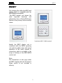
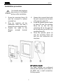
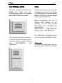
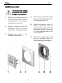
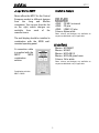
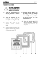
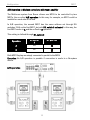
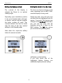
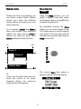
Konfiguration M217 R45of of M217 Wall Display Unit E 2.01 Re:control M217 Wall display M217 General Installation advice & Multiroom Planer Safety Guidelines 2 2 2 3 Connection schematic M217 4 GIRA M217 5-6 Feller EDIZIOdue 4217.M 7-8 Revox Adaption: Jung & Merten 9-10 Connection plan 11 Configuration IR receiver Addressing A/B operation 12 12 13 14 Menu Control Operating with softkeys Contrast & Time Timer Menu Timer programming Sleep function 15 15 16 17 17 24 Guarantee and Delivered items Care Technical data 25 25 26 1 Re:control M217 Wall display M217 Installation height Please read these instruction through completely and carefully before setting the unit up. The ideal installation height for the M217 display unit is approx. 150 cm / 59 inch (centre of display). This results in a good reading angle and comfortable operation of the display unit/ operating unit combination for smaller people as well. The operating unit should be attached below the display unit. General Ideally, the wall display is combined with the M218 keypad to enable simply and logical operation of your music equipment. Multiroom Planer V2.00 The new Multiroom Planner doesn't just calculate the correct address assignment for the M219 Side room amplifiers and M217 Wall-mounted displays, it also calculates the slot addresses for the M200 series Re:control products in the side room. Take advantage of the possibility to be able to determine in advance, all M200, M219 and M217 addresses simply and quickly and at the same time save the information as system documentation. You will find more information about addressing the M219 in the side room, on Page 13 of this manual. You can download the new Multiroom Planner V2.00 free-ofcharge from the download area of the Revox Homepage, under www.revox.com. The four softkeys are assigned different operating functions, depending on the menu selection The Main menu shows information about the current program, e.g. multimedia module, CD. The basic operations such as Source, Track+-, Volume, etc. are carried out using the connected keypad M218 or through a Revox IR remote control. The Timer menu organises timed processes in the Multiroom system, e.g. time, day, volume, source, etc., while the Server menu allows you to control the Music server. The IR receiver that is integrated in the display transfers the control signals to the Multiroom equipment. 2 Re:control M217 Danger warning Installation Improper mounting of this device in an environment with low-voltage products (230 V AC) can cause serious health problems or damage to property. This product is intended for connection to extra low voltage circuits and may never be connected to low voltage (230 V AC). The device may only be mounted, connected and removed by qualified personnel. Qualified personnel are persons who are authorised to perform the required tasks and recognise and prevent possible dangers thanks to their education, experience and instruction in the relevant standards, requirements and accidentprevention regulations. The information and instructions in this installation manual must always be observed to avoid danger and damage. Installation of the wall display in combination with a low voltage device (power connection) should only be carried out if you are certain that the unit is isolated from the power source. Installation should be carried out in accordance with the valid national domestic installation guidelines, e.g. NIN. In particular, the directive NIN 4.9.1.ff is valid if the wall display is to be combined with a low voltage device with power connection. Combinations with low voltage devices are only permitted if these devices also have a simple basic insulation. 3 Re:control M217 Connection Revox recommends using a 4-lead telephone cable (1 x 4 x 0.5 mm²) with an RJ11 plug (6P4C modular) for connection to the Revox multiroom system or Revox secondary M219 room amplifier. Maximum cable length: 100 m Max. cable resistance: 0.1 Ω /m M217 The cabling for the combination of the 217 display and the 218 keypad should be done as shown in the drawing. With the combination solution, the 218 keypad only has a connection to the 217 display. There is no direct connection to the Additional room amplifier. Via the connection d the M217 is directly connected to the devices Re:system M10, M100, M51 or in case of a Multiroom installation to the corresponding room amplifier M217. The ferrite ring is included in the delivery of the M217 (except for Feller). Connection c comes preassembled with the combination solution. Tip M219/ M51/ M100 Before laying cabled, you should check whether this cable is suitable for an RJ11 socket. Combination : Display unit M217 and keypad M218 (optional) 4 M217 GIRA M217 The company Gira offers the M217 wall display, which is compatible with the REVOX Multiroom system. The M217 display unit shows the most important functions and information from a Revox Multiroom System in the primary and secondary rooms. Combination M217 + M218 (optional) Ideally, the M217 display unit is combined with the M218 operating unit, which enables easy and logical operation of the music system. A connection cable is included in the scope of delivery of the M217/M218 control unit. Note: The illustrations on this page show the M217 display with the Gira Esprit frame, which is not included in delivery. 5 M217 Installation procedure You should avoid applying any pressure to the display during or after installation. 1. 2. 3. Screw the mounting fixture (4) onto the recessed or surface mounted box. Strip the insulation off the installation cable and feed it through the mounting fixture (4). Connect the cable to the Phoenix screwed terminal block. 4. 5. 6. Connect the terminal block with the print connector on the back of the operator panel (1) Locate the operator panel (1) with its frame (3) onto the mounting fixture (4), so that the clip connectors (2) on the panel (1) line up with the cut-out (5) in the mounting fixture (4). Press the operator panel (1) onto the mounting fixture (4) until the clip connectors clip into place. DIP switches (back) The basic settings are configured with the DIP switches on the back of the M217. Use a small screwdriver for this purpose. 6 M217 Feller EDIZIOdue 4217.M Advice The Swiss company Feller offers the 4217.M wall display from their EDIZIOdue series, which is compatible with the REVOX Multiroom system. The IR receiver must be activated if the wall display is used on its own without a 4218.M keypad. In this case, the DIL switch 1 on the back of the wall display must be switched on (IR on). Revox recommends the use of ITPlus® RJ45 sockets for the interface to the main system (Re:system) and/ or the M219 side room amplifier. Single socket = 1198-118.XXX.ITS; double socket = 1198-428.XXX.ITS. The 1900-0.XXX throughway boxes are recommended for speaker cable. The wall display should be installed in combination with the 4218-M keypad. A connection cable is supplied with the Feller 4217/4218.XXX.2x1 wall combination. Please note The EDIZIODue wall display may not be used to switch 230V low voltages. Combi solution 4217.M + 4218.M 7 M217 Installation procedure You should avoid applying any pressure to the display during or after installation. 1) Install the mounting fixture (5) with the fixing plate (4) onto the recessed box or the surface mounted box on the wall. 2) Strip the insulation off the U72 installation cable and feed it through the mouting fixture (5). 3) Connect the cable to screwed terminal block. the 1 3 2 4) Connect the terminal block with the print connector on the back of the operator panel (1). 5) Locate the operator panel (1) with its frame (3) onto the mounting fixture (5), so that the locating springs (2) on the panel (1) line up with the slots in the mounting fixture. 6) Press the operator panel (1) onto the mounting fixture (5) until the springs clip into place. 4 8 5 6 M217 Jung / Merten M217 Available designs Revox offers the M217 for the Central European market in different designs from the Jung and Merten companies. You can see from the list on the right, which designs are available from each of the manufacturers. JUNG CD 500 / universal JUNG CD plus JUNG LS990 / LS plus Colours: Alpine white Other colours and designs are available on request at additional cost, if applicable. The wall display should be installed in combination with the M218 wallmounted operating panel. Merten M-SMART Merten M-ARC Merten M-PLAN I/II Merten M-PLAN glass frame Colours: Polar white A connection cable is supplied with the M217/ M218 combination solution. Other colours and designs are available on request at additional cost, if applicable. Combination solution M217 + M218 9 M217 Installation procedure You should avoid applying any pressure to the display during or after installation. 1) Screw the mounting fixture (4) onto the recessed or surface mounted box. 2) Strip the insulation off the installation cable and feed it through the mounting fixture (4). 5) Locate the operator panel (1) with its frame (3) onto the mounting fixture (4), so that the clip connectors (2) on the panel (1) line up with the cut-out (5) in the mounting fixture (4). 6) 3) Connect Phoenix block. the cable to the screwed terminal 4) Connect the terminal block with the print connector on the back of the operator panel (1). 10 Press the operator panel (1) onto the mounting fixture (4) until the clip connectors clip into place. Re:control M217 Connection plan M217 Setup and operation The wall display must be connected to a Revox Re:system device or a Revox M219 Additional room amplifier for setup. Technical data Advice Information about and support for setup and operation can be found in the Revox manuals. Protection IP20 in accordance with IEC529; Dry installation Build-in depth 20 mm Temperatures Operation: -5°C to +45°C Storage: -25°C to +70°C Cable Installation cable U72 ABG 1 x 4 x 0.5mm² DIL switches Factory settings 1: IR off 2: AB operation off 3: Address off 4: Address off 11 Konfiguration M217 M217 Configuration Important The basic settings for the M217 are made with the four DIL switches on the back of the unit. Use a small screwdriver or the point of a ballpoint pen to set the switches. The addressing of the M217 and the M219 must be setup correctly to ensure error free operation. The configuration must be done while the unit is removed from the power, otherwise any changes made will not be effective. Please note: ON is with the switch in the upper position. NO 1 2 3 4 Function M217 IR eye on/off A/ B operation M217 Address M217 Address Factory setting On Off Off Off M217 Infrared receiver on/off If you are combining the M217 display with the M218 remote control, which also has an IR receiver, one of the two IR receivers must be disabled, as otherwise IR commands will be carried out double. In some cases, e.g. in buildings with glass internal walls, it can be advantageous to switch of the IR receiver on the M217, in order to avoid conflicts with other devices. The only switch that can be set during operation of the unit is DIL switch 1 for the IR receiver. IR Function DIL switch 1 IR - On On IR - Off Off DIL position 1 1 With the M217, the integrated IR receiver is located in the lower right-hand display field. 12 Re:control M217 M217 Address setting Connection to a Re:system device (M10, M100, M51) If the M217 is connected directly to a Re:system device (M-Link) the address setting is not significant. The M217 will be recognises automatically. Connection to the M219 side room amplifier If, on the other hand, the M217 is to be connected to a M219 side room amplifier, address setting is very important. The M217 address defines which M219 should be communicated with. In this way, the M217 address is set through DIL switches 3 & 4, based on the M219’s address. Use the free-of-charge Multiroom Planner 2.00 software from Revox for the addressing. You will find more about this under www.revox.com. The M218 keypad is not taken into account during addressing as it has no own address. The M218 keypad can always be connected to a M219 Additional room amplifier or a M217 display. Example: If the M219 has address 2, address 2 must also be set at the M217 Display. Address DIL switch 3 DIL switch 4 1 Off Off 2 Off On 3 On Off 4 On On DIL position 3 4 3 4 3 4 3 4 Within in one zone, all M217s must have different addresses as otherwise there can be communication problems. The maximum number of M217 in any one zone is restricted to 4. The revisal of a correct addressing is made in the Setup menu of the Re:system device, category Multiroom / Version. All attached devices (M219 and/or M217) must be listed in the respective zone. 13 Konfiguration M217 A/B Operation: 2 displays control one side room amplifier The Multiroom system from Revox allows one M219 to be controlled by two M217s, the so-called A/B operation. In this way, for example, an M217 could be installed on each side of the bed. In A/B operation, the second M217 has the same address set through DIL switches 3 & 4 as the first M217, but with DIL switch 2 activated. In this way, the first M217 works in A and the second in B operation. This setting is defined through DIL switch 2. Operation DIL switch 2 A Off B On DIL position 2 2 Both M217 Displays are simply connected in parallel to the M219. Exception: No A/B operation is possible if connection is made to a Re:system device. A/B operation 14 Re:control M217 Operating with Softkeys MAIN MENU Softkeys are used for control so that the M217 display remains clear to use, in spite of the large number of options available. The main menu shows you clearly detailed information in the M217 display. The control is effected either by the connected wall control unit M218 or by a IR remote control. A Softkey is a key that can be assigned different functions depending on which menu is currently active. This avoids an overcrowded display as only current important functions are displayed. Display operation The M217 menu fulfills two tasks. The first task is the display of Furthermore, the Revox-menu control is designed in such a clear and simple way as to make the operation of the M217 intuitive. information about the current music program. The selection of the audio source is done through the M218 keypad respectively the remote control (IR). The second task is the operation of the timer, including the Sleep function. The M217 offers 4 independent timers for each room. 15 Operation M217 Setting the display contrast Setting the time in the side room The contrast of the display is adjusted by Revox to an optimal reading angle. The time can also be set from a side room, assuming that an M217 Wallmounted display is being used. Depending upon installation position it can occur however that a stronger or weaker contrast attitude supplies the better reading off result. This contrast attitude can later be made with the help of the two marked softkeys in the Standby mode. Switch the side room off and press and hold the two highlighted keys for approx. 2 seconds. The display now changes to the Set Clock mode. Here, you can set the time and the weekday using the 4 keys on the M217 display. The Exit key returns you to the normal operating state. Hold down the respective softkey button for several seconds. L Display contrast setting If you only press one of the highlighted display buttons, you modify the display contrast setting. 16 Re:control M217 Timer programming TIMER MENU The concept of the programming is as follows: The Timer is the control centre of the Multiroom system. Using the Timer, you can set a wakeup alarm for specific days or lull yourself off to sleep with the Sleep function. timer Firstly, you select one of the four Timers and then assign it the required properties. The following figure shows the inside Timer display field with the corresponding assignments. The Timer is called with the Timer softkey on the M217. The first time it is called, the following display appears: Timer status Timer no. Sleep time Weekday Volume Source 17 Operation M217 Timer selection The Select options Select Select The properties of the individual Timers can be set with the Select softkey: c Switching time d Weekday e Volume f Select timer source g (Select tuner station) Timer 1 has been selected in the above example. The individual Timers can be selected with the Timer soft keys. There are a total of 4 independent Timers to choose from. If you reach Timer 4, pressing the softkey again brings you back to Timer 1. You can scroll through a loop of the selection options by repeatedly pressing the Select key: Switch-on time [Hours] Switch-on time [Minutes] Switch-off time [Hours] Switch-off time [Minutes] Weekday [ ... ] Volume [ ... ] Timer source [ … ] (Tuner station [ ... ]) Timer 1 Timer 2 Timer 3 Timer 4 The two square brackets […] indicate that this part can be edited according to your requirements with the softkeys . 18 Re:control M217 Only switch on or off c Switching times Select Sometimes, it is useful just to switch the music equipment on at a specific time and switch it off manually, or vice-versa. Once you have selected a Timer, you can define the switch on/off times with the Select softkey. The first time the Select key is pressed, the first counter pair appears in square brackets. In order to make only one timepoint active, you select the display **:** when setting the hours value. This appears between 23h and 0h and the minute value is not relevant. As soon as a timer’s settings are modified however, this is automatically activated. First, using the softkeys, you define the switch-on time and then the switch-off time. In the above example, Timer 1 starts at 7:15am and remains active until it is switched off manually. Timer 2 always switches off at 9:30pm, irrespective of when it was manually switched on. Switch-on Switch-off | | Hours Minutes | | | | [8]:[15] – [9]:[20] Please note If a timepoint is selected for the switch-off, which is earlier than that chosen for the switch-on, e.g. 20:15 – 08:30 the switch-on occurs at 8.15pm on the selected day and switch-off occurs at 8:30am, on the following day. 19 Operation M217 d Weekday Select Once you have defined the switch-on and switch-off timepoints, by pressing the Select key again, you can reach the next stage where you define the weekdays when the timer is to be activated. M T W T F S S SS MTWTF MTWTFS MTWTFSS Timer weekday examples: As well as the individual days from Monday to Sunday, you can also select from specific day groups. SS Æ only Saturday and Sunday The individual weekdays are identified by the following letters: MTWTF Æ from Monday to Friday MÆ Monday T Æ Tuesday WÆ Wednesday T Æ Thursday FÆ Friday SÆ Saturday SÆ Sunday MTWTFS Æ from Monday to Saturday MTWTFSS Æ daily, Monday to Sunday Example: With the setting MTWTF, the timer will wake you each day from Monday to Friday but will let you have a lie-in on Saturday and Sunday. Selection is made from an endless loop of options that you can step through using the softkeys . The following weekday setup options are available: 20 Re:control M217 f Select timer source e Volume Select Select After selecting the weekday(s), the next time you press Select, you will be prompted to set the volume level that should be used. The Multiroom module timer offers your three sources that can be activated when the timer kicks in. These are Tuner, DVD/CD and Aux/Server. Please note Using the softkeys, you set the volume level between 1 (very low) and 9 (very loud). When selecting the source, you should bear in mind that the source that will be selected is what was assigned to the Tuner, DVD/CD or Aux/Server through the Remote menu. Volume 1 Volume 2 : : : Volume 8 Volume 9 If instead of assigning DVD to the DVD module (Fig c), Aux-1 is assigned instead (Fig d), the timer would switch Aux-1 on. (See therefore next page) This function can be used specifically to call up external sources through the timer. You must of course make sure that the external source is also active when it is called by the timer. 21 Operation M217 g Select Tuner station 1 Select Assuming that you have selected Tuner as your source, a further press of Select will bring you to the point where you can select the station you want to listen to. If you have selected DVD/CD or Aux/Server on the other hand, you will return to the Switching times selection level. 2 3 Ç Remote menu Re:system The third option in the Remote menu is to deactivate a source (Fig e). In this case, the timer would not call up any source at the defined timepoint, even though a source had been defined in the Timer menu. In this field, you can select the radio station that should be played by choosing one of the up to 50 stored favourite stations. If you select a number that is higher than the actual number of stored positions, the station stored on position 1 will automatically be played. L You can find further information on this topic in the corresponding user manuals of the Re:system devices under the function REMOTE. Example: 25 stations are stored but the station number 30 is selected through the Select option. In this case, station 1 will actually be played. 22 Re:control M217 Activate Timer Timer status & time display As default, the individual Timers are deactivated. As soon as the switching times of a Timer are modified, the corresponding Timer is activated automatically and the small bell symbol in the top line of the display changes from showing c to d If one or more Timers are activated, two bell symbols are displayed when the M217 is in standby mode. Both bell symbols only disappear once all Timers have been deactivated. The time and the weekday display are controlled through the Multiroom module. 1 Please refer to the Clock setting section on page 16 or of the Multiroom chapter in the corresponding Operating instructions. 2 All Timers deactivated Each of the Timers can however be activated or deactivated manually. To activate a Timer, selected the required Timer with the Timer softkeys. Using the softkeys, the Timer can be activated or deactivated. One or more Timers active 23 Operation M217 Nested events Sleep function Sleep Through the Timer programming, you can create nested events. Nested events occur when two different events address the same source and at the same time. Using the Sleep function, you can define a length of time after which the Re:system device or the M219 will automatically switch off. By repeatedly pressing the Sleep softkey, you can step through a loop in 15 minute steps, to set the required time period. The loop starts with 90 minutes and ends with switching the Sleep function off. In our example, Event 1 and Event 2 have a time overlap. Since they both address the same source, Event 1 defines the switch-on point while Event 2 defines the switch-off time. ON OFF 90‘ 75‘ 60‘ 45‘ 30‘ 15‘ OFF s Event 1 Event 2 ON OFF Active time The current Sleep time setting is shown in the top line of the display. L In the case of nested events then, the event that occurs at an earlier timepoint defines the switch-on and/or switch-off timepoints. 24 Re:control M217 Guarantee Care The guarantee period is 24 months from the date of purchase. Clean the user surface, including display and keys as well as the frame, with a damp cloth. Apply a few drops of non-abrasive, washing-up liquid to the damp cloth to remove any stubborn marks. Your dealer should be your first contact if you need service. If he can't give you the help you need, send the M217 Display without any accessories to your national Sales Office. Please supply a complete description of the problem and a full return postal address. WARNING: Thinners, acetone and toluene should not be used. Their use can cause the material to become brittle and crack and damage the lettering. Disposal Revox products should be disposed of or recycled in compliance with local regulations governing the disposal and/ or recycling of electrical and/electronic equipment. Delivered items M217 wall display Operating instruction Toroidal core 25 Appendix M217 Technical Data Connections Max. cable lengths: VCC: + 8 to 20 V A: Bus-communication B: Bus-communication GND: Ground / screening 100m M217 - Re:connect M219 100m M217 - Re:system M10, M100, M51 30 m M217 - Re:control M218 keypad Power consumption: at the M51: 30 - 50 mA at the M219: 50 - 100 mA Operating conditions: (off –max. brightness) (off –max. brightness) (Humidity class acc. to DIN 40040), "+10°... +40°C" Errors and technical modifications excepted. 26 Re:control M217 27 Appendix M217 M217 Display Operating instructions / Part no.: 10.30.3019 28