1
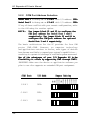
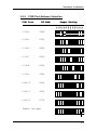
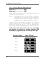
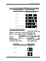
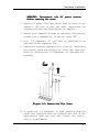
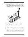
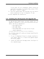
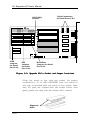
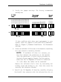
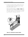
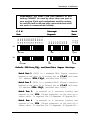
Hardware Installation REMEMBER: the same COM port address or IRQ setting CANNOT be used by more than one port in your system. Each port assignment must be unique, or a conflict will result and your connected device will not work or communicate reliably. Baud Rate 115200 230400 460800 IRQ5 IRQ7 IRQ9 IRQ10 IRQ11 IRQ12 IRQ15 IRQ3 IRQ4 2E0 260 368 268 360 270 COM7 COM8 COM9 COM10 COM11 COM12 Interrupt Request 2E8 COM4 2F0 COM5 3E0 COM6 3F8 COM1 2F8 COM2 3E8 COM3 COM Port S1 3F8 COM1 IRQ4 115200 S2 2F8 COM2 IRQ3 115200 Default COM Port,IRQ, and Baud Rate Jumper Settings Serial Port 1 (SIO1) is a standard DB-9 (9-pin) connector mounted on the card. It is factory set as C O M 1 with base I/O address 3F8h 3F8h,IRQ4 IRQ4, and baud rate 115200. Serial Port 2 (SIO2) is a standard DB-25 (25-pin) connector mounted on the card. It is factory set as C O M 2 with base 2F8h,IRQ3 IRQ3, and baud rate 115200. I/O address 2F8h Serial Port 3 is mounted on a connector bracket and connects to the SIO3 (10-pin connector) on the card via a ribbon cable. It requires the I/O Expander 4S Upgrade Kit. Serial Port 4 is mounted on a connector bracket and connects to the SIO4 (10-pin connector) on the card via a ribbon cable. It requires the I/O Expander 4S Upgrade Kit. 3-1 I/O Expander 4S User's Manual 3-2.2 COM Port Address Selection Serial Port 1 is factory set as C O M 1 with I/O address 3F8h Serial Port 2 is factory set as C O M 2 with I/O address 2F8h If any of these conflict with your current configuration, refer to the following for another option. NOTE: Use jumper block S1 and S2 to configure the COM port address for Serial Port 1 and 2 respectively. Use jumper block S3 and S4 to configure the COM port address for optional Serial Port 3 and 4 respectively. The basic architecture for the PC provides for four COM ports: COM1-COM4. However, as computer technology and applications continue to evolve, more types of devices have become available to expand your system’s capabilities... resulting in a potential shortage of available system resources! One of the advantages of your I/O Expander 4S is the flexibility it offers by supporting COM1 through COM12. IMPORTANT: Make sure the device or application software you plan to use also supports an extended COM port assignment. 3-2 0 COM12 0 COM11 8 COM10 8 COM9 0 COM8 3E8h 0 COM7 COM3 COM5 2F8h 0 COM6 COM2 8 COM4 3F8h COM2 COM1 Jumper Setting 8 COM3 I/O Addr COM1 COM Port Hardware Installation 3-2.2 COM Port Address Selection COM8 260h COM9 368h COM10 268h COM11 360h COM12 270h COM5 0 COM12 2E0h 0 COM11 COM7 8 COM10 3E0h 8 COM9 COM6 0 COM8 2F0h 0 COM7 COM5 0 COM6 2E8h 8 COM4 COM4 COM2 Jumper Setting 8 COM3 I/O Addr COM1 COM Port Disable (all open) 3-3 I/O Expander 4S User's Manual 3-2.3 Interrupt Request (IRQ) Selection Serial Port 1 is factory set as IRQ4 Serial Port 2 is factory set as IRQ3 If this conflicts with your current configuration, refer to the following for another option. NOTE: Use jumper block S1_IRQ and S2_IRQ to configure the IRQ setting for Serial Port 1 and 2 respectively. Use jumper block S3_IRQ and S4_IRQ to configure theIRQ setting for optional Serial Port 3 and 4. Currently AT/Pentium computers support 16 interrupt channels; however, not all are available to you. Some are reserved for system use (IRQ 0, 1, 2, 8, 13) and others have been used for standard installed devices such as mouse, fax/ modem, printer, sound card, floppy drive, etc., leaving only the high IRQs (IRQ10 and above) for further expansion. Your I/O Expander 4S allows for maximum expansion and flexibility by supporting both low and high level IRQs. IRQ3 IRQ4 IRQ5 IRQ7 IRQ9 3-4 IRQ5 IRQ7 IRQ9 IRQ10 IRQ11 IRQ12 IRQ15 Jumper Settings IRQ3 IRQ4 Interrupt Request Hardware Installation 3-2.3 Interrupt Request (IRQ) Selection (continued) Jumper Settings IRQ3 IRQ4 IRQ5 IRQ7 IRQ9 IRQ10 IRQ11 IRQ12 IRQ15 Interrupt Request IRQ10 IRQ11 IRQ12 IRQ15 Disable (all open) 3-2.4 Baud Rate Selection Baud Rate is factory set as 115200. Baud Rates 230400 and 460800 are reserved for software developers only. Use jumper block S1_BAUDRATE and S2_BAUDRATE to configure the Baud Rate for Serial Port 1 and 2 respectively. Use jumper block S3_BAUDRATE and S4_BAUDRATE to configure the Baud Rate for optinal Serial Port 3 and 4 respectively. NOTE: Jumper Setting 115200 230400 460800 Baud Rate *115200 230400 *= Factory Default 3-5 I/O Expander 4S User's Manual 3-2.4 Baud Rate Selection (continued) Jumper Setting 115200 230400 460800 Baud Rate 460800 Disable (all open) 3-3 Installing Your I/O Expander 4S After you have verified the jumper settings on your I/O Expander 4S, proceed with the following instructions to install it in your computer. General instructions are given since the design of computer cases varies. Refer to your computer’s reference manual whenever in doubt. 1. Turn OFF the power to your computer and any other connected peripheral devices. Follow the precautions for static electricity discharge. WARNING: STATIC ELECTRICITY DISCHARGE may permanently damage your system. In order to avoid possible static electricity discharge during installation procedures, please follow the guidelines below: • Discharge any static electricity build up in your body by touching a large grounded metal surface such as the computer case (if plugged in), a metal window frame, refrigerator, or water tap for a few seconds. • During installation procedures, avoid any contact with internal parts. Handle cards only by their edges. 3-6 Hardware Installation WARNING: Disconnect the AC power source before removing the cover. 2. Unplug all power cords and cables from the back of the computer. (Be sure to note the cable connections for reconnection when the installation is complete.) 3. Remove your computer’s cover by removing its mounting screws with a screwdriver. Slide the cover OFF. 4. Your I/O Expander 4S card must be installed in an available 16-bit expansion slot. 5. Remove the selected expansion slot cover by unscrewing the holding screw and sliding the cover out. Save this screw for securing the I/O Expander 4S card after it’s installed. Figure 3-1: Remove the Slot Cover 6. To install the I/O Expander 4S card, carefully align the card’s bus connector with the selected bus slot on the motherboard. Push the card down firmly, but gently, until it is well seated. 3-7 I/O Expander 4S User's Manual NOTE: Hold the card by its external edges only. Try to avoid touching the components, connectors or pins. 7. Replace the cover slot holding screw to secure the card to the rear slot panel. 03 S1 04 S1 Figure 3-2: Installing the I/O Expander 4S Card 8. Replace the computer’s cover and screws. 9. Reconnect all cables and power cord to the back of the computer. 10. Turn your computer ON and verify that the I/O port addresses are recognized and set properly. Most computers will display a system configuration table, including port addresses when it is powered ON or rebooted. 3-8 Hardware Installation If the ports are not recognized, please review the installation procedures. For further help, contact SIIG's BBS and/or technical support. 11. Turn the system power OFF and make any new serial device connections to the I/O Expander 4S card. You have completed the installation. 3-4 Installing the I/O Expander 4S Upgrade Kit To add two more serial ports, you must install the I/O Expander 4S Upgrade Kit, which can be purchased from your dealer. This kit is comprised of: • Two 16C550 chips • One 1488 chip* • Two 1489 chips* • One bracket with one 9-pin and one 25-pin serial connectors *The chips, 1488 and 1489, are now built into the I/O Expander 4S. The following steps will guide you through installing the kit’s components. 1. If your I/O Expander 4S board is already installed in your system, remove it to install the upgrade chipset and verify jumpers. 2. Install the 16C550 into the empty socket. See figure 3-3 for a detailed layout. 3-9 I/O Expander 4S User's Manual 16550 Chip Sockets 10-pin Connectors for Serial Ports 3 & 4 3F8 COM1 2F8 COM2 3E8 COM3 2E8 COM4 2F0 COM5 3E0 COM6 2E0 COM7 260 COM8 368 COM9 268 COM10 360 COM11 270 COM12 IRQ3 IRQ4 IRQ5 IRQ7 IRQ9 IRQ10 IRQ11 IRQ12 IRQ15 115200 230400 460800 SIO4 6 SIO3 1 6 1 SIO1 U5 S1 S1-IRQ S1 S2 S2-IRQ S2 S3 S3-IRQ S3 S4 S4-IRQ S4 U6 SIO2 U7 U8 COM Jumpers for Serial Port 3 & 4 IRQ Jumpers for Serial Port 3 & 4 Baud Rate Jumpers for Serial Port 3 & 4 Figure 3-3: Upgrade Kit’s Socket and Jumper Locations Align the notch on the chip and socket for proper orientation. It is VERY IMPORTANT that the notch on the chip is matched with the notch on the socket. Make sure all pins are aligned with the socket holes; then gently press the chip into the socket until seated. Alignment Notch 3-10 Hardware Installation Verify the jumper settings. The factory recommended settings are: Baud Rate IRQ7 IRQ9 IRQ10 IRQ11 IRQ12 IRQ15 IRQ5 270 COM12 360 COM11 368 COM9 268 COM10 2E0 COM7 260 COM8 3F8 2F8 3E8 2E8 2F0 3E0 COM1 COM2 COM3 COM4 COM5 COM6 Interrupt Request 115200 230400 460800 COM Port IRQ3 IRQ4 3. S3 3E8 COM3 IRQ10 115200 S4 2E8 COM4 IRQ11 115200 If this conflicts with other port assignments in your system, reset the jumpers to non-conflicting addresses. Refer to Chapter 3, Hardware Installation for alternative settings. 4. Select an available I/O slot next to the board for installing the two-connector mounting bracket. NOTE: If available I/O slots is a concern, you may also remount the connectors on the bracket into the punch-out I/O port holes provided on the back of most computer chassis. For this option, make sure the I/O Expander 4S board is installed in a slot where the cables can be connected. Remove the selected slot’s cover by unscrewing the holding screw and sliding it out. Save this screw for securing the connector bracket. 5. Install the I/O Expander 4S board by carefully aligning the board’s bus connector with the selected bus slot on 3-11 I/O Expander 4S User's Manual 6. To install the connector bracket, carefully slide it into the selected rear panel slot where the slot cover had been removed. Replace the holding screw to secure the connector bracket in place. 7. Connect the 10-pin connector on the end of each serial port’s attached ribbon cable to the SIO3 and SIO4 10-pin connectors on the I/O Expander 4S board. It does not matter which connector on the board they are attached to. However, make a note as to connections so you will know each port’s COM address and IRQ. SIO3 SIO4 ,,,,, @@@@@ ÀÀÀÀÀ @@@@@ ÀÀÀÀÀ ,,,,, @@@@@ ÀÀÀÀÀ ,,,,, @@@@@ ÀÀÀÀÀ ,,,,, @@@@@ ÀÀÀÀÀ ,,,,, @@@@@ ÀÀÀÀÀ ,,,,, 03 S1 1 Note: Please match the colored wire edge with pin 1. 04 S1 1 Figure 3-4: Installing the Connector Bracket 3-12 Hardware Installation IMPORTANT NOTE: The colored stripe imprinted on the ribbon cable indicates the pin 1 side of the cable’s connector. Make sure this is matched with pin 1 on the board’s connector 8. Replace the computer’s cover and screws. 9. Reconnect all power cords and cables to the back of the computer. Connect your serial peripherals to the I/O Expander 4S ports. You have completed the installation. Most computers will display a system configuration table, including port addresses when it is powered ON or rebooted. Turn your computer ON and verify that the I/O port addresses are set properly. 3-13