1
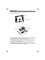
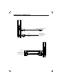
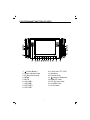
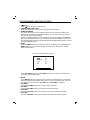
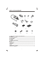
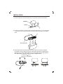
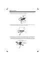
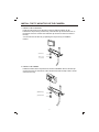
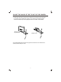
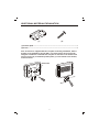
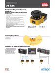
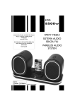
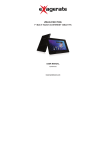
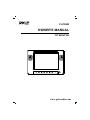
PLVW8M
OWNER'S MANUAL
TFT MONITOR
www.pyleaudio.com
INSTALLATION
The monitor (Fig.1) can be installed on the bracket (Fig.2). You can mount the unit
according to the following steps.
Monitor
Slot 2
Mounting Bracket
Slot 1
Fig.1
Position Plate
Screw Cover 1
Rotation Top
Screw Cover 2
Base
Rotation Base
Fig2.
1. Insert the position plate on the bracket into the slot 1 on the mounting bracket. Then
slide the position plate upward to the slot 2 and select the proper location. Then
rotate the screw cover 2 to fix the monitor on the bracket.
2. When mounting the monitor on the bracket, you can release the screw cover 1 to
turn the rotation top upward or downward to find a good viewing angle, then rotate
the screw cover 1 to fix the rotation top.
3. The monitor can be rotated leftward or rightward by rotating the rotation base.
4. On the bottom of the base, there is a layer of magic tape. When you remove the
protective paper, you can stick the unit to the desired location of your vehicle system.
Be sure that the mounting surface is clear and dry.
2
ELECTRICAL CONNECTION
To other DVD/VCD system
REMOTE
RED
To the +12V
power terminal
Ground wire
BLACK
DC PLUG
S-VIDEO IN
(YELLOW) (WHITE) (RED)
VIDEO IN(YELLOW)
AUDIO L IN(WHITE)
AUDIO R IN(RED)
3
LOCATION AND FUNCTION OF KEYS
13
13
12
12
14
16
17
15
11
10
3
4
9
8
7
1. (Power Button)
2. Power Indicator Light
3. IR (Remote Sensor)
4. MENU
5. MUTE
6. VOLUME+
7. VOLUME8. PICTURE+
9. PICTURE-
6
5
2
1
11
10. 8 inch color TFT LCD
11. Speakers
12. Volume Knob
13.
Jacks for Earphone
14. REMOTE Jack
15. DC 12V Input Jack
16. S-VIDEO Jack
17. AV IN Jacks
4
LOCATION AND FUNCTION OF KEYS
1.
(Power)
Press
button (1) to turn on/off the unit.
2. POWER INDICATOR LIGHT
When the system is on, the indicator light (2) will be illuminated.
3. REMOTE SENSOR
For option, the monitor can be supplied with the remote control according to the
user's need. Through the remote sensor IR (3), you can use the remote control to
execute TV operation conveniently.
If there is a VIDEO/AUDIO system connecting to the monitor through the REMOTE
jack (14) and AV INPUT jacks (17), through the remote sensor IR (3), you can use
the corresponding remote control supplied with the VIDEO/AUDIO system to control
the VIDEO/AUDIO system.
4. MENU
Press the MENU button (4) to show the menu on the display (10), repeatedly press
MENU button (4) to select among Bright, Contrast, Color, Tint (For the unit with
NTSC system) items.
(For the unit with NTSC system):
MENU
Bright
32
32
Contrast
Color
32
Tint
32
Press PICTURE+ button (8) or PICTURE- button (9) to increase or decrease the
level of the corresponding item.
5. MUTE
Press MUTE button (5) to mute the sound. Press the button again, the screen will
display the AUDIO level setting value of the TV unit for several seconds. Then you
can adjust the volume level by VOLUME+ (6) and VOLUME- (7) buttons.
6. VOLUME+
Press the VOLUME+ button (6) to choose channel upward.
7. VOLUMEPress the VOLUME- button (7) to choose channel downward.
8. PICTURE+
Press the PICTURE+ button (8) to increase the volume level of the speaker.
9. PICTUREPress the PICTURE- button (9) to decrease the volume level of the speaker.
5
LOCATION AND FUNCTION OF KEYS
10. TFT LIQUID CRYSTAL DISPLAY
The 8 inch TFT color LCD (10) can show the current state of the unit.
11. SPEAKER
There are two speaks (11) on the front of the monitor. The sound can be sent
from the speakers if the unit isn't connected with earphone.
12. EARPHONE VOLUME CONTROL KNOB
Slide the knob (12) to change the volume of the earphone.
13. JACKS FOR EARPHONE
There are two jacks (13) for earphone. You can connect earphone to any one of
the jacks to receive sound signal.
14. REMOTE
Through the REMOTE jack (14), connect other VIDEO/AUDIO system to the
monitor. Then you can control the VIDEO/AUDIO system by pointing the remote
control directly to the remote sensor IR (3).
15. DC 12V INPUT JACK
Through this jack (15), provide DC 12V power supply to the unit.
16. S-VIDEO JACK
The jack (16) is used for S-VIDEO input.
17. AV INPUT JACK
The group of jacks (17) is used for VIDEO in, AUDIO R in and AUDIO L in.
6
TROUBLE SHOOTING
Before going through the checklist, check wiring connection. If any of the problems
persist after checklist has been made, consult your nearest service dealer.
NO POWER
Check if the power button on the front of the monitor is set to on.
Check if the wires of DC power plug are properly connected.
Check if there is power at the power supply outlet.
THE PICTURE IS OVER DARK, OVER BRIGHT OR HAS NO COLOR:
Press MENU button on the front of the unit, then press PICTURE+ button or
PICTURE- button to increase or decrease the level of the corresponding item
(BRIGHT, CONTRAST, COLOR or TINT) to proper value, then you can get an
optimum picture effect.
NO SOUND
Check if the audio connections are properly connected.
Check if the volume is minimum, and press the VOLUME+ button to increase the
volume level.
CAN'T RECEIVE TV SIGNAL OR THE PICTURE QUALITY IS POOR IN TV MODE:
Please confirm if the antenna is connected to the antenna socket of the unit.
Check if you have pulled out the antenna.
Perhaps the signal of your position is too weak, and it can't receive any TV signal
at all.
BUTTONS DO NOT WORK
Turn the unit off and on with the power button on the front of the unit.
7
BRACKET 3 (BKT3)
8
INSTALLATION HARDWARE
(2)
(3)
(4)
(5)
(1)
(6)
(7)
(a)
(9)
(8)
(b)
(10)
(11)
(12)
(13)
(14)
(1) ASSY (Rotate combined bracket with Base A..................................................1
(2) Base B................................................................................................................ 1
(3) Plastic tube ( 13mm) ........................................................................................ 2
(4) Screw ( 3x10)..................................................................................................... 4
(5) Clip screw
..............................................................................................1
(6) Fastener ............................................................................................................1
(7) Fix bolt .............................................................................................................. 2
(8) Washer (a) (3mm thick) ......................................................................................1
(9) Tray ..................................................................................................................... 1
(10)sponge (a) ......................................................................................................... 1
(10)sponge (b) ......................................................................................................... 1
(11)Hex nut
......................................................................................................... 1
(12)Bolt ..................................................................................................................... 1
(13)Washer (b) (7mm thick) ......................................................................................1
(14)Plastic tube ( 16mm) ........................................................................................ 2
9
INSTALLATION
1. Press the switch under the headrest of the car seat and pull out the headrest.
Headrest
Switch
2. Combine the base B (2) and the base A with steel ripple pipe (1), then place them
on the poles of the removed headrest to select proper hole position to install the
base.
(2)
(1)
Steel ripple pipe
3. Remove the Base from the headrest and loosen the two screws by using the
screwdriver, then according to the size of the poles, place the two plastic tubes
( 13mm) (3) or plastic tubes ( 16mm) (14) on the holes that you just selected,
then adjust them to proper position as shown in diagram below.
(3) Plastic tube( 13mm)
or (14)Plastic tube( 16mm)
10
INSTALLATION
4. Place the Base on the poles of the removed headrest in good position, and then
use four screws (3x10
ø
(4) to fix the base A and base B.
(4) Screw
(1)
(2)
5. Install the headrest with the Base to the car seat in proper position, then use the
screwdriver to rotate the two screws tightly to fix the base.
6. Use the fix bolt (7) and the fastener (6) to install the tray(9) to the steel ripple pipe.
Before installing the tray, stick the smaller quadrate sponge (a) to the tray and
stick the larger quadrate sponge (b) to the inner side of the fastener according to
the arrow in the figure below, Doing this can ovoid scraping the steel ripple pipe.
(10)Sponge (a)
(10)Sponge (b)
(6)Fastener
(7)Fix bolt
(9)Tray
11
INSTALL THE TV MONITOR OR THE CAMERA
1. INSTALL THE TV MONITOR
Insert the clip screw (5) into the hole on the tray with the washer (a) (8)
between the clip screw (5) and the tray. Then aim the clip screw to the hole on
the bottom of the TV monitor and rotate the clip screw to fix the TV monitor to
the tray.
You can also use the fix bolt (7) replacing the clip screw (5) to install the
monitor.
(8)Washer(a)
(5)Clip screw
or (7) Fix bolt
2. INSTALL THE CAMERA
Install the camera to the tray like the TV monitor installation above. Aim the clip
screw to the hole on the bottom of the camera and rotate the clip screw to fix the
camera to the tray.
(8)Washer(a)
(5)Clip screw
12
ADJUST THE ANGLE OF THE TV UNIT OR THE CAMERA
1. Rotate the clip screw to loosen the TV monitor or the camera, then rotate the
TV monitor or the camera left or right to your need for good viewing angle
and then rotate the clip screw tightly to fix the TV monitor or the camera.
(5)Clip screw
or (7) Fix bolt
(5)Clip screw
2. The steel ripple pipe can be bent to get the TV monitor or the camera in the
proper position that your need.
13
ADDITIONAL MATERIAL EXPLANATION
(1)
(2)
(1) Position plate........................................................................................................1
(2) Screw...................................................................................................................4
If the TV monitor is supplied with the root plate for the bag installation, when it
changes to be installed by the unit BKT3, you must remove the six screws by
using the screwdriver to uninstall the root plate on the back of the monitor and
use four screws (2) to install the position plate (1) to the bottom of the monitor,
as shown below.
Root Plate
(1)
(2)
14
www.pyleaudio.com
88-T1325-02