1
OPERATING INSTRUCTIONS FOR
Model 8800A & B
Trace Moisture Analyzer
DANGER
HIGHLY TOXIC AND OR FLAMMABLE LIQUIDS OR GASES MAY BE PRESENT IN THIS MONITORING
SYSTEM.
PERSONAL PROTECTIVE EQUIPMENT MAY BE REQUIRED WHEN SERVICING THIS SYSTEM.
HAZARDOUS VOLTAGES EXIST ON CERTAIN COMPONENTS INTERNALLY WHICH MAY PERSIST
FOR A TIME EVEN AFTER THE POWER IS TURNED OFF AND DISCONNECTED.
ONLY AUTHORIZED PERSONNEL SHOULD CONDUCT MAINTENANCE AND/OR SERVICING. BEFORE
CONDUCTING ANY MAINTENANCE OR SERVICING CONSULT WITH AUTHORIZED SUPERVISOR/
MANAGER.
Teledyne Analytical Instruments
P/N M8800A&B
12/19/01
ECO # 01-0382
i
8800 Series Trace Moisture Analyzer Instruction Manual
When calling your representative for technical support, please have your serial numbers available.
The Sensor and Instrument Serial Numbers are on the instrument, also see section 3.4.4.4.
Sensor Serial No.: _______________
Instrument Serial No.: _______________
Your Representative is:
Except as may be provided by contract, this document and all specifications and drawings contained are the property of Teledyne Analytical
Instruments, are issued in strict confidence, and shall not be reproduced
or copied or transmitted, in any form or by any means, or used as the basis
for the manufacture or sale of apparatus, programs, or services without
permission.
Document No.: XDO.01.D.0000 Rev.2 5/10/00
Copyright © 2000 by Teledyne Analytical Instruments
i
8800 Series Trace Moisture Analyzer Instruction Manual
The manufacturer reserves the right to change or modify the product specification and / or appearance at
any time without notice. Therefore, the information in this document is subject to change without notice
and does not represent a commitment on the part of the manufacturer.
The customer agrees that in accepting and using this instrument the
manufacturer’s liability arising from or in any way connected with
this instrument shall be limited exclusively to performing a new calibration or replacement or repair of the instrument or sensor, at the
manufacturer’s sole option, as covered by the manufacturer’s warranty. In no event shall the manufacturer be liable for any incidental,
consequential or special damages of any kind or nature whatsoever,
including but not limited to lost profits arising from or in any way
connected with this instrument or items hereunder, whether alleged
to arise from breach of contract, express or implied warranty, or in
tort, including without limitation, negligence, failure to warn or strict
liability.
Swagelok, Cajon are trademarks of SWAGELOK Co.
Acrobat is a trademark of Adobe Systems Incorporated
Epson is a registered trademark of Seiko Epson Corporation
Microsoft Windows is a registered trademark of Microsoft Corporation
ii
8800 Series Trace Moisture Analyzer Instruction Manual
Examine the 8800 Series Trace Moisture Analyzer package for damage or mishandling. If any damage is evident notify the carrier and request an inspection.
Unpack the box, it should contain: The 8800 Series Trace Moisture Analyzer, sensor in desiccant container, connectorized cable, and this manual.
PLEASE READ THIS MANUAL IN WHOLE, PRIOR TO INSTALLING OR
REMOVING THE SENSOR FROM ITS SHIPPING CONTAINER.
This manual is organized in three sections:
Section 1 is an overview of the 8800 Series Trace Moisture Analyzer.
Section 2 describes the sensor and sampling techniques.
Section 3 describes the instrument’s electrical, mechanical, and user interfaces.
This manual is intended for those already familiar with the installation, use and
maintenance of analytical or process instrumentation.
Those acquainted with other Teledyne dewpoint measurement products such as the
8800P portable trace moisture analyzer or the 8800T, will benefit from the commonality of the user interface.
Warning Labels
The symbols shown below appear on the instrument to alert the user of potentially
hazardous conditions.
Protective Grounding Conductor Terminal
Bornier de L’Ecran de Protection
Schutzerde
CAUTION - Risk of Electric Shock
ATTENTION - Risque de Décharge Électrique
ACHTUNG - Hochspannung Lebensgefahr
CAUTION - Refer to documentation
ATTENTION - Se Réferer aux Documents Joints
ACHTUNG - Beachten Sie beiliegende Dokumente
iii
8800 Series Trace Moisture Analyzer Instruction Manual
Warranty
This instrument is warranted to be free from defects in workmanship and materials. Liability under this
warranty is limited to servicing, calibrating, and replacing any defective parts of the instrument returned to
the factory for that purpose. Fuses are specifically excluded from any liability. This warranty is effective
from the date of delivery to the original purchaser. The equipment must be determined by the manufacturer
to have been defective for the warranty to be valid. This warranty applies as follows:
• one year for electronics
• one year for mechanical failures to the sensor
• six months for calibrations
If damage is determined to have been caused by misuse or abnormal conditions of operation, the owner
will be notified and repairs will be billed at standard rates after approval.
Maintenance Policy
In cases when equipment fault is suspected, please notify your representative of the problem, be sure to
provide them with model and serial numbers. If the problem can not be resolved, then ask for a Return
Authorization Number (RAN) and shipping instructions. Issuance of an RAN does not automatically imply
that the equipment is covered by our warranty, that will be determined after we receive the equipment.
Pack the equipment in a suitable box with sufficient padding, include the RAN number on your paperwork,
and send the equipment, prepaid, to the designated address. Equipment returned without an RAN, or with
reversed shipping or import/export charges, will not be accepted
If the warranty has expired, or the damage is due to improper use or exposure of the equipment; then the
repair facility will provide an estimate and wait for approval before commencing repairs.
For your convenience a Return Authorization Request Form is provided in appendix N, it must be completed and sent back to the provided destination in order to obtain a RAN.
iv
8800 Series Trace Moisture Analyzer Instruction Manual
Table of Contents
1.0 Overview of the 8800 Series Trace Moisture Analyzer.......................................................1
2. Sensor and Sampling Techniques ..........................................................................................3
2.1 Precautions using the sensor ................................................................................................3
2.2 Sensor Technical Specifications ..........................................................................................4
2.3 Sensor Installation & Sampling Techniques........................................................................4
2.3.1 In-situ Installation .............................................................................................................5
2.3.2 Extractive Installation .......................................................................................................6
2.4 Mechanical Installation........................................................................................................7
2.5 Troubleshooting unexpected readings .................................................................................8
3. Instrument ..............................................................................................................................9
3.1 Precautions using the 8800 Series Trace Moisture Analyzer ..............................................9
3.1.1 Electromagnetic Compatibility Considerations ................................................................9
3.2 Instrument Technical Specifications..................................................................................10
3.3 Installation .........................................................................................................................11
3.3.1 Instrument Mechanical Installation ................................................................................11
3.3.1.1 8800A (DIN43700) Enclosure Installation..................................................................11
3.3.1.2 8800B (IP65) Enclosure Installation............................................................................11
3.3.2 Electrical Connections ....................................................................................................12
3.3.2.1 Connecting Power........................................................................................................12
3.3.2.1.1 AC Mains Electrical Power Connection ...................................................................13
3.3.2.1.2 Low Voltage DC Powered Option - Electrical Power Connection...........................13
3.3.2.2 Sensor Connection .......................................................................................................13
3.3.2.3 Wiring the Alarm Contacts ..........................................................................................13
3.3.2.4 Interfacing to the Analog Output .................................................................................14
3.3.2.5 Interfacing to the RS-232 option .................................................................................15
3.4 Operating the Instrument ...................................................................................................15
3.4.1 Starting up.......................................................................................................................15
3.4.2 Display Conventions.......................................................................................................16
3.4.3 Push Buttons ...................................................................................................................16
3.4.4 Operating State ...............................................................................................................17
3.4.4.1 Viewing Dewpoint Mode.............................................................................................17
3.4.4.2 Alarms..........................................................................................................................19
3.4.4.3 Start Calibration ...........................................................................................................20
3.4.4.3.1 SpanCheck™ Mode ..................................................................................................20
3.4.4.3.2 Single Point Self Calibration, manual or scheduled .................................................22
3.4.4.4 Viewing Serial Number Mode .....................................................................................25
3.4.5 SetUp State .....................................................................................................................25
3.5 Resetable Audio-Visual Alarm Option (NFPA compliant) ...............................................28
3.6 Troubleshooting the Instrument.........................................................................................29
3.7 Maintenance.......................................................................................................................31
Glossary ...................................................................................................................................33
Appendix A: Flow Diagram of Operating State User Interface ..............................................37
Appendix B: Flow Diagram of Set-Up State User Interface ...................................................39
Appendix C: Sensor Mechanical .............................................................................................40
v
8800 Series Trace Moisture Analyzer Instruction Manual
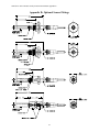
Appendix D: Optional Sensor Fittings.....................................................................................41
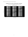
Appendix E: 8800 Series Trace Moisture Analyzer Circuit Board Dimensions .....................42
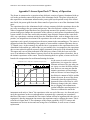
Appendix F: Sensor/SpanCheck™ Theory of Operation ........................................................45
Appendix G: Dewpoint Response time Analysis ....................................................................46
Appendix H: Sample Gas Filter Considerations......................................................................48
Appendx I: 8800 Series Trace Moisture Analyzer Grounding Considerations .......................49
Appendix J: Analog Output vs. Dewpoint...............................................................................50
Appendix K: RS-232C Interface Protocol ...............................................................................52
Appendix L: Procedure for Exchanging 8800 Series Sensors .................................................55
Appendix M: Uncertainty in LBS & ppmV calculations ........................................................56
Appendix N: Extractive Sampling System Internal Assembly.................................................57
Index.........................................................................................................................................58
vi
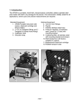
Section 1: Introduction
1.0 Overview of the 8800 Series Trace Moisture Analyzer
The 8800 Series Trace Moisture Analyzer is a microprocessor based hygrometer, for measuring
moisture content in gases in the range from -100°C to +20°C dewpoint depending on the sensor
ordered. The 8800 Series uses a Hyper Thin Film HTF™ sensor which is encapsulated in sintered
stainless steel, thus it is capable of coming into contact with a wide variety of environments.
However one should keep in mind that the sensor is a delicate device and it should be handled
accordingly.
The measurement is displayed on the instrument’s custom LCD, can be transmitted by optional
analog and digital outputs, and can control optional programmable relays. Four front panel buttons provide the user with a rich feature set. The 8800 Series Trace Moisture Analyzer’s advanced
design allows it to be housed in a variety of enclosures.
The 8800 Series has an impressive set of dewpoint measurement capabilities in terms of accuracy,
stability, response time etc. The specifications of the sensor are discussed in section 2.2, while the
specifications of the instrument are discussed in section 3.2. A summary of the standard and
optional features & capabilities of the 8800 Series are listed below as an overview aid to the user.
Standard Features/Capabilities
• Locking of instrument, preventing unintentional changes
• SpanCheck™: - automatic recalibration using room air, all instruments pre-calibrated at factory.
• Capability to enter up to 15 NIST/NPL traceable calibration points at factory, depending on
order.
• Manual Self Calibration: a single point calibration using a known standard gas. High acccuracy can be maintained even in the most harsh applications.
• Pressure correction: built-in software calculation of dewpoint at a pressure different than the
measurement.
• Cable length compensation: automatic self measuring software.
• Universal autoranging AC supply 100-250VAC
• Instrument and Sensor: UL & cUL listed/recognized; CE electromagnetic compatibility certified
Optionally ordered Features/Capabilities
• Password protected Locking of instrument, preventing unauthorized changes
• Alarm Relays - programmable set points, error handling, and hysteresis. Up to 3 alarm relays
may be ordered. On-display legends indicate relay states.
• Audio Visual Alarm- complies with recommendations of NFPA 99, 1996 edition, audio reset
and test buttons.
• Analog Output- factory set voltage or user selectable 4/20 - 0/24 mA. Includes installation
testing features. User selectable range (low & high point) of analog output.
• RS-232C interface - allowing the user digital data access to the instrument.
• Interval-timer-scheduled Self Calibration, a single point calibration using a known standard
gas, can operate an electrically actuated switchover valve for unattended calibrations
• Large variety of threads for sensor mounting into sample
• Low voltage DC power operation 15-30VDC
• Intrinsically Safe Approved NEC and CENELEC standards (UL & DEMKO) configurations
1
8800 Series Trace Moisture Analyzer Instruction Manual
2
Section 2: Sensor and Sampling Techniques
2. Sensor and Sampling Techniques
2.1 Precautions using the sensor
The HTF™ Al2O3 sensor is designed and field proven to be highly reliable, rugged and maintenance free. However the user should consider the following precautions:
• If the instrument is used to measure moisture in toxic, flammable, or explosive gases, the sample outlet must exhaust to a safe place.
• Check the sample line for leaks before and after connecting.
• If measuring gases at high pressures, make sure the sample system is depressurized before
installing or removing the sensor probe, or other items e.g. filters.
• To avoid the need for prolonged dry-down (when expecting to measure dewpoints dryer than
–65ºC), do not expose the sensor to room air longer than necessary (1 - 2 minutes). Thus, do
not open the sensor container before you are ready to install the sensor.
• The sensor container has desiccant to keep the sensor dry during shipping and to avoid damage due to condensation. Close the container immediately after removing the sensor to avoid
degradation of the desiccant.
• Do not throw away the sensor container, you may use it again to transport the sensor between
locations, to store it between uses or to ship it back to the factory for certification. The container can be attached to the sensor cable, by trapping the cable with the lid strap.
• Do not expose the sensor to corrosive gases such as gases containing chlorine, ammonia or
HCl. (SO2 can be monitored when the moisture content is low).
• Except for the XTR65W sensor:
1. Do not expose the sensor to liquid water, as it may get damaged.
2. Do not breathe directly onto the sensor, as condensation may form which could damage
the sensor element.
• Do not install the sensor near heat sources such as radiators or air ducts.
• Do not install the sensor in places subject to extreme mechanical vibration or shock. If this is
not avoidable, use resilient mounting. If in doubt, call your representative.
• Do not disassemble the porous metal filter encapsulation, as this will damage the sensor and
void your factory warranty.
• Prior to installation of the probe, ensure that no contaminants are present in the system (e.g.
oil, liquid water).
3
8800 Series Trace Moisture Analyzer Instruction Manual
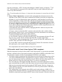
2.2 Sensor Technical Specifications
Type: ..................................Hyper Thin Film HTF™ high capacitance Al2O3.
Dewpoint range:.................XTR-100: -148°F to +68°F (-100°C to +20°C)
XTR-65: -85°F to +68°F (-65°C to +20°C).
Capacitance:.......................15nF to 200nF.
Accuracy: ...........................±5.5°F (±3°C) refer to appendix M for accuracy expressed in other units of measure.
Repeatability: .....................±0.9°F (±0.5°C).
Response time:...................refer to Dewpoint Response time analysis in Appendix G.
Operating Temperature: .....-10°C to +70°C.
Storage Temperature: .........-40°F to+176°F (-40°C to +80°C).
Sample Flow range: ...........(linear velocity @ 1ATM): Static to 100m/s.
Enclosure: ..........................encapsulated in 100µ sintered stainless steel.
Calibration method: ...........Highly uniform sensors calibrated at low dewpoint and SpanCheck™, sensor saturates at dewpoint
above +68°F (+20°C). NIST/NPL traceable multi-point factory calibration available optionally.
Pressure operating range:...Standard:500 PSI (34 bar).
...........................................Optional:5,000 PSI (340 bar).
Mechanical connections:....14mm x 1.25mm sparkplug threads, and ¾”-16 threads, standard
Optional configurations: G1/2, 1/2”NPT, 5/8”-18 and others
Electrical connections ........Female BNC connector.
Sensor signal cable: ...........RG58 coaxial cable, or for lengths greater than 100’ RG6 coaxial cable, max 3,000’.
Approvals/Classifications: .CE for electromagnetic compatibility, accredited laboratory tested and certified
UL and cUL for ordinary use
Intrinsically Safe configurations: for NEC standard IS Simple Apparatus: UL
for CENELEC standard IS Simple Apparatus: DEMKO ,
refer to labeling
2.3 Sensor Installation & Sampling Techniques
Keep in mind that the moisture content at the sensor is not only due to the moisture of the gas
being measured, but also due to desorption of water from tubing, trapped moisture (at the interconnection points, valves, filters and other hygroscopic materials in the system), leaks in the system, and others. Thus the measurement may vary from the expectation, and therefore care should
be taken in choosing the sampling technique utilized in the measurement. Factors such as gas
pressure, flow rate, materials of construction, length and diameter of tubing, number of interconnecting fittings, dead space in tubing and manifolds; will influence the measurement value and
response time.
The high capacitance HTF™ sensors can be installed either directly in the line to be sampled (insitu), or in a slip stream of a sample system (extractive).
To assure a long and accurate performance of the sensor, it should be protected from contaminants
such as liquids (water, oil etc.), and particulates. The sintered stainless steel sensor encapsulation
protects from particulates larger than 100 microns, finer particulates (e.g. from degraded desiccant or rust) should be filtered with a particulate filter with suitable capability, do not use hygroscopic filter materials. Refer to Sample Gas Filter Considerations Appendix H.
4
Section 2: Sensor and Sampling Techniques
2.3.1 In-situ Installation
In-situ installation is recommended only for measurements where the gas pressure is expected to
vary little, the gas is expected to be free of contaminants, the gas temperature is within the operating specifications of the sensor, and there is no chance of liquids coalescing. Examples of applications suited for in-situ installations are: pure gases, output of desiccant dryers (for instrument air),
glove boxes, etc. For most other applications in-situ installation should be avoided for the following reasons:
• Sample conditioning is almost always necessary to avoid exposure of the sensor to liquid
water and other contaminants, such as hydrocarbons, which may damage the sensor or affect
accuracy over time.
• Variations in line pressure affect the reading of the sensor because dewpoint varies with pressure.
• If the gas line is under pressure, it is more likely that water condensation occurs which may
damage the sensor.
• Under a pressurized system removal of the sensor without the installation of isolation valves
can be dangerous.
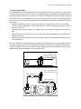
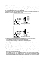
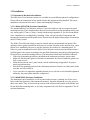
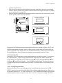
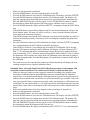
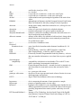
If in-situ installation is required, bypass mounting is preferable; make sure to install the sensor at
the upper surface of the gas line to minimize its exposure to liquid water, should condensation
occur, the XTR65W sensor is best suited for these applications. Also consider the need to isolate
(depressurize) before installing or removing the sensor.
In-Line Installation, Sensor
Measuring at Line Pressure
NOT RECOMMENDED
Main
Gas Line
Bypass Installation, Sensor
Measuring at Line Pressure
Sample Cell
Safety shut-off Valve
Main
Gas Line
Safety shut-off Valve
Bypass
Control
Valve *
* maintain differential pressure to provide adequate flow through sample cell
5
8800 Series Trace Moisture Analyzer Instruction Manual
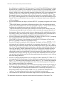
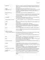
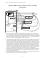
2.3.2 Extractive Installation
For extractive installations we recommend our sample system ESS, which may be equipped with
a variety of features, such as: isolation valve, coalescing or particulate filter, pressure regulator,
calibration sample injection or extraction port, pressure gauge, flow meter, weatherproof enclosure. Refer to the ESS literature for more information.
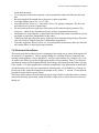
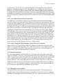
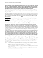
If the resources to make your own sample system are available, the following two diagrams may
be used as a guideline to configure a simple system.
Main
Gas Line
Sample Cell
Extractive Installation, Sensor
Measuring at Line Pressure
Regulator or
Needle Valve
Main
Gas Line
Regulator or
Needle Valve
Safety shut-off Valve
Sample Cell
Exhaust
Exhaust
Extractive Installation, Sensor
Measuring at Ambient Pressure
It is generally recommended to measure at ambient pressure for the following reasons:
• The readings will not be affected by variations in line pressure.
• The risk of exposing the sensor to liquid water is significantly reduced.
• ppm readings are computed for a pressure of one atmosphere (1 bar); and have to be corrected
using software in the instrument, or a pressure monograph, or calculator if the sensor is measuring at different pressures.
If readings at line pressure are necessary, it is recommended to measure at ambient pressure and to
use the instrument’s pressure compensation feature to calculate the dewpoint at line pressure.
Refer to Viewing Dewpoint Mode section 3.4.4.1.
Please make sure that:
• The sample is taken from the upper surface of the main gas line. This avoids problems with
contamination. The sample should be taken away from pipe line walls where flow rates may
be low, and dewpoint changes may lag.
• For dewpoints dryer than -40°F, use stainless steel tubing only. Copper tubing is acceptable
for dewpoints wetter than -40°F. Do not use plastic, rubber or tygon tubing under any circumstances, as measurements would be incorrect and/or response time slow due to water retention
6
Section 2: Sensor and Sampling Techniques
•
•
•
•
•
•
•
•
inside these materials.
Try to run pipes to the sensor upwards, so that contaminants tend to fall back into the main
line.
Keep the length of the sample line to the sensor as short as possible.
Use small diameter pipes (1/4” or 1/8” OD).
Use sufficient flow rates (e.g. 1 l/min with 6 feet of 1/8” piping is adequate). The flow rate
will influence the systems’ response time.
Do not install any devices upstream of the sensor, such as other measuring systems, flow
meters etc., which are not absolutely necessary as these are potential leak sources.
Installation of a coalescing and / or particulate filter ahead of the sensor is desirable to prevent
any liquid or particulate contamination of the sensor.
If filters are used upstream of the sensor, make sure these contain non-hygroscopic filter materials only. Refer to Sample Gas Filter Considerations Appendix H.
If pressure regulators, shut off valves etc. are used upstream of the sensor, make sure these do
not contain rubber or other hygroscopic materials.
2.4 Mechanical Installation
The sensor probe has two thread sizes for mounting to the sample cavity where the dewpoint will
be measured, see appendix C. Various optional fittings are available for direct connection into
existing system openings, refer to appendix D. Ask your representative for a Sample Cell, if you
do not have the ability to provide an appropriate sample cavity mounting. If the ¾”x16 thread is
used then the sensor will seal against the wall of the sample cell with the provided Viton A O-ring.
If the 14mm x 1.25 spark plug thread is used then an additional Viton gasket must be installed to
provide the proper seal. Ask your representative for this gasket, it is available free of charge. To
prevent any leaks, tighten the fitting into the sample cavity, with a 11/4” wrench, 1/8 turn past finger-tight to assure metal-to-metal contact.
The sensor can be removed from the fitting by unscrewing it. Make sure that the sensor is securely
fastened to the fitting (the tension washer should be compressed), so that it does not come loose
during use.
7
8800 Series Trace Moisture Analyzer Instruction Manual
2.5 Troubleshooting unexpected readings
If erroneous readings are suspected on a newly acquired instrument, compare the serial number
engraved on the sensor sintered filter, to the label on the instrument. The two should be the same;
if they are not, the instrument may not be calibrated with the installed sensor. To troubleshoot
other problems, identify the unexpected reading category in the following table, and consider the
possible causes and appropriate diagnostic action and remedy.
Symptom
Reading is not
changing
Slow Response
Dry Reading
Possible Cause
Condensation in sample system.
It is usually more satisfactory to bleed a sample gas at atmospheric pressure through
the sensor sampling chamber, and to use 1/8” (3mm) o.d. sample pipe.
SpanCheck™, wrongly set, or faulty Sensor.
Verify SpanCheck™, or return sensor for full calibration to your representative.
Leak in system or use of unsuitable pipe.
Cure the leak, or replace unsuitable pipe with copper or stainless steel. Flexible connections should be made with PTFE pipe. NEVER use rubber or plastic pipe.
Comparison of readings with manual cooledmirror instrument.
This type of indicator reads about 10ºC dry at about -50ºC dewpoint due to temperature gradients within the device. The error increases at drier levels.
Prolonged exposure to wet gas.
Dry down the sensor, install sensor in either a known dry gas stream i.e. instrument
quality air or dry nitrogen, or place sensor in a dry can or bottle of desiccant and seal
the container from outside air (the shipping container is designed for this purpose)
also see section 3.4.4.3.1
1. Instrument Failure
Disconnect cable from input terminals, if the instrument still reads SHR the problem
is with the instrument. However, if the instrument reads OPN then recconect the cable
to the input terminals and check possible causes 2 or 3.
2.Short circuit on sensor cable or connections.
Disconnect cable from sensor and if meter still reads SHR, cure the short circuit in the
cable or connections or replace cable; otherwise check the sensor.
SAT
Display Shows
SHR
3.Short circuited sensor.
1. Instrument failure.
Display Shows
OPN.
Condensation will occur if the temperature of the sample system, at any point is below
(colder) the dewpoint temperature of the sample gas. Once having formed, the sample
reaching the sensor will have a dewpoint equal to the temperature of the condensation,
regardless of the dewpoint of the source gas.
1. Water vapor in the system.
2. Flow rate too low.
3. Sample pipe too large and/or too long.
4. Unsuitable sample pipe.
5. Leaks.
6. Hygroscopic materials in sample system
Wet Reading
Display Shows
Diagnostic/Remedy
See below re sample pipe material, also see section 2.3
Disconnect cable from sensor and note that the meter reading returns to OPN. Use a
new sensor, or apply approximately 20V DC to the sensor MOMENTARILY with the
sensor in a known dry condition. Polarity is not important, but the contact MUST be
very brief or the sensor may be damaged.
Short the SIG and SHIELD contacts of the sensor input terminal, if the instrument
reads SHR the problem is in the cable or sensor, otherwise return the instrument for
service.
2. Open circuit on cable.
Disconnect cable from sensor and short center pin of plug to the outer shell. If the display still shows OPN, repair cable.
3. Open circuit on sensor.
Check sensor connection or replace sensor.
For non-sensor related problems (e.g. no reading on instrument) refer to section 3.6
8
Section 3: Instrument
3. Instrument
3.1 Precautions using the 8800 Series Trace Moisture Analyzer
The 8800 Series Trace Moisture Analyzer uses state-of-the-art microelectronics to provide a compact full functioning instrument. The user should consider the following precautions when using
any sensitive electronic device.
• Observe the appropriate electrical safety codes and regulations. Consult with National Electrical Code article 400, and/or other nationally or locally recognized procedures relevant to your
installation. You will most probably require a disconnect switch, and power wiring. The
power cord provided with the instrument is intended only for testing, it may not be used for a
permanent field wired installation. This instrument is UL approved for field wiring.
• If weather proofing is required consult your representative for an optional enclosure. The
8800 Series Trace Moisture Analyzer is not intended for direct outdoor installation unless it is
appropriately housed.
• Do not install the unit near heat sources such as radiators or air ducts.
• Do not install the unit in places subject to extreme mechanical vibration or shock. If this is not
avoidable, use resilient mounting. If in doubt, call your representative.
3.1.1 Electromagnetic Compatibility Considerations
The 8800 Series Trace Moisture Analyzer has been designed and verified by testing to meet the
requirements of the EC Council EMC Directive 89/336/EEC, for Industrial, Scientific & Medical
equipment. The sensor ground is isolated from the AC ground, logic ground, 4-20mA loop return,
etc.; however they are also shunted with a 0.1uf capacitor 1M Ohm resistor, and a 33V Transient
Voltage Suppressor; this prevents electrostatic buildup, noise pick-up, and in conjunction with the
internal fuse protects the instrument from over-voltage inputs. Please consider the following electromagnetic interference issues during installation:
• In order to provide an acceptable noise environment for the 8800 series Trace Moisture Analyzer or any other digital equipment in the proximity of switched inductive loads, it is recommended that there be varistors placed across the inductors to keep down the high voltage
spikes during transitions.
• Any circuitry which is activated by relay contacts should account for the contact bounce, one
simple debouncing method is placing a capacitor across the relay contacts.
• AC power wiring should be routed as far away from the 8800 Series Trace Moisture Analyzer
and its wiring as practical.
9
8800 Series Trace Moisture Analyzer Instruction Manual
3.2 Instrument Technical Specifications
Enclosure: .........................8800B tabletop or surface mount, watertight IP65 tested, and NEMA 12 tested
8800A panel-mount, DIN 43700 dimensional standard, optional NEMA 12 type protection gasketing
available
Dimensions & Weight:......8800B: 4.73” x 6.3” x 3.55”, 2.1 lbs (fully optioned) w/cables.
8800A: 5.67” x 2.84” x 2.95” DIN 43700 standard, 1.3 lbs (fully optioned) w/cables.
refer to appendix E for detailed dimensions
Environmental Range: ......Operating temperature of electronics: 14°F to 122°F (-10°C to 50°C)
Storage temperature of electronics: -40°F to 176°F (-40°C to 80°C)
Humidity: 0 to 90% RH non-condensing
Altitude: 0 to 6500 feet (2000 meters)
Mains Supply Voltage:......100 to 250VAC autoranging, 50/60Hz, 10VA, internal 0.5A, 250V fast acting fuse.
Optionally the instrument may be configured with DC power capability: 15 to 30VDC 0.5A.
Electrical connections: ......21 contact pluggable screw terminal block, 1.3mm diameter pins on 5mm centers.
Wiring requirements: ........ For AC Power: 18AWG or heavier wire, an external means for disconnecting the power source is
required to meet National Electrical Code requirements.
For Sensor signal: RG58 coaxial cable, or RG6 for cable longer than 100’. A 6 foot cable is provided as
a standard, other lengths ordered as options. When changing cable, refer to cable compensation section.
Input resolution:................0.1°C dewpoint.
Indicators: .........................3.5 digit backlit LCD with custom legends, audible indicator.
Engineering units: .............°C,°F, PPM, LBS H2O/mm scf,gm H2O/m3.
Controls:............................Four push buttons, user’s selections are stored in EEPROM.
Outputs:............................. Analog: voltage by order or current user selectable 4-20mA or 0/24mA. Linear to the selected engineering units, the range is programmable. Output resolution is 0.1°C dewpoint, linearity 1%, max load
resistance 500 Ohms.
Digital RS-232C (9600,8,E,1), can interface to a Personal Computer or other RS-232 device.
Alarm relay contacts: ........Ordinary use, explosion-proof housed, and safe area instruments: 10A, 250VAC or 30VDC.
Intrinsically Safe Div 2 instruments use hermetically sealed relays: 3A, 120VAC
Isolation: ...........................Sensor is isolated from power ground, analog output and RS-232, but they are shunted with a 33V transorb, a 1M Ohm resistor and 0.1uF capacitor. Refer to Electrical Connections section.
Approvals/Classifications: CE for electromagnetic compatibility, accredited laboratory tested and certified
UL and cUL for ordinary field wired use
Intrinsically Safe configurations: for NEC standard IS installations UL,
for CENELEC standard IS installations DEMKO,
refer to instrument labeling
10
Section 3: Instrument
3.3 Installation
3.3.1 Instrument Mechanical Installation
The 8800 Series Trace Moisture Analyzer is available in several different physical configurations.
Please follow the instructions below, which describe the instrument being installed. The sensor
installation is discussed in Section 2: Sensor and Sampling Techniques.
3.3.1.1 8800A (DIN43700) Enclosure Installation
The standard 8800A Trace Moisture Analyzer is provided with two clip-on compression panel
mounting brackets. These brackets allow the user to mount and secure the instrument onto a properly cutout panel (137mm x 67mm). Consult with drawing in appendix E, for all relevant dimensions. Installation is accomplished by attaching 2 clips, one on each side of instrument, and
inserting the instrument into the panel cutout. Pressure must be applied along edges of instrument
until it is firmly seated.
The 8800A Trace Moisture Analyzer may be ordered with an environmental seal option. This
option provides a gasket (installed at the factory) to seal the face plate to the enclosure box, and a
gasket (to be installed by the user) to seal the enclosure box to the user’s mounting panel. To
achieve a good environmental seal the 8800A Trace Moisture Analyzer must be mounted onto a
rigid flat panel with a cutout according to the specified dimensions, using the provided panel gasket and all four provided mounting brackets. The instructions listed below should be followed.
• If the clip-on mounting brackets are installed on the instrument enclosure, remove them.
• Make sure that the panel gasket is flat and even around the box bezel. Handle the gasket carefully as not to tear it.
• Insert the box into the user’s panel cutout, consult with drawing in appendix E for proper
panel cutout dimensions.
• Attach all four mounting brackets to the instrument enclosure from the rear of the panel, make
sure they are fully locked in.
• Use a screwdriver to tighten the mounting bracket screws, all four screws should be tightened
uniformly, the panel gasket should be compressed.
3.3.1.2 8800B (IP65) Enclosure Installation
The instrument can be installed as a wall or panel surface mount, by making use of four screw
holes on the back (bottom) of the instrument enclosure. Open the instrument cover for access to
these screw holes. They are located at the corners of the enclosure and outside of the NEMA seal.
Do not drill other mounting holes, as you may compromise the seal. Refer to Appendix E for all
relevant dimensions.
11
8800 Series Trace Moisture Analyzer Instruction Manual
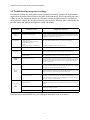
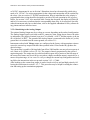
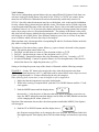
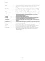
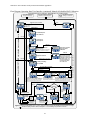
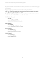
3.3.2 Electrical Connections
All connections are made via a 21 contact, pluggable screw terminal block referred to as P1.
Pluggable Block Terminals
1
2
3
4
5
6
7
8
9
10
11
12
13
14
15
16
17
18
19
20
21
0.5A 250V
Power Supply Module
4.3mH
0.0047uf
0.1uf
275VAC
0.0047uf
RFI filter board
Sensor
Measuring
Circuitry
0.1uf
1M Ohm
33V 400W
Logic ground and AC Power
ground are connected for safety
and electromagnetic
interference considerations
LO
Ordinary relay contacts: 10A, 250VAC or 30VDC
Hermetically Sealed relay contacts: 3A, 120VAC
ALARMS*
HI
AC LIVE
AC Power Input:
AC NEUTRAL
100 to 250VAC, 50/60Hz, 10VA
Not Connected
AC GROUND
white
SIG-IN
SENSOR CABLE
SIG-RET black
A-OUT Analog Output 4/20mA or 0/24mA or Voltage *
A-RET
TxD
RS 232 I/O *
CAUTION: Connecting the RS-232C interface
RxD
on instruments which do not have the option
installed, will damage the instrument.
RET
+DC power 15V OUTPUT and/or 15-30V INPUT* 0.5A
PS+
AC GROUND
Not Connected
NC
NO
C
Not Connected
NC
NO
C
Instrument Circuit board
Note: * Options will function only if they are installed
Cable access to the 8800B enclosure is through three ports (refer to appendix E), which maintain
the NEMA integrity:
• One 1/2” NPT conduit fitting, may be used for high or low voltage connections. This port is
intended for the power and high voltage relay wiring.
• Two watertight cable grips located at the bottom of the instrument: for low voltage wiring
only such as sensor, analog output, RS-232, or relays when used with low voltages. They
accommodate cables with diameters 0.196” to 0.315”. To install a cable, loosen the nut, feed
the cable through the grip and tighten the nut again. Unused cable grips should be plugged to
maintain the integrity of the enclosure.
3.3.2.1 Connecting Power
The 8800 Series Trace Moisture Analyzer is typically provided to be field wired to operate from
AC Mains Power of 100 to 250VAC, 50/60Hz, 10VA, the instrument has an internal 0.5A, 250V
fast acting fuse. However the 8800 Series Trace Moisture Analyzer can also be optionally ordered
12
Section 3: Instrument
to operate from 15 to 30 VDC 0.5A, with an internal 0.5A fast acting fuse. Please follow the
appropriate installation procedures in the paragraphs below according to the electrical power
option on your instrument. Do not connect to AC power without a proper ground connection.
For Intrinsically Safe installations, first make sure that the equipment is qualified for the particular installation, it should have a label specifying the certifications and the approving agency. Then
follow the appropriate control drawing as well as the instructions in the relevant paragraphs in this
manual.
3.3.2.1.1 AC Mains Electrical Power Connection
The 8800 Series Trace Moisture Analyzer is provided with a 6 foot (2 meter) internationally
approved AC power cord, terminated with a connector according to the ordered option. This cable
is connected to the pluggable screw terminal block; however it is provided strictly as a means of
testing the instrument, it should not be used in the final installation. The 8800 Series Trace Moisture Analyzer is intended as a field wired instrument permanently connected and installed according to the local, nationally recognized procedures for equipment of this type and stated power
requirements. For North American installations use UL 62 and/or CSA C22.2 No 49, 18AWG
cable with black, white, and green color codes. For European and other international installations
use CENELEC harmonized type cable, with 0.82mm wire size or equivalent 10 amp use, with
brown, light blue, and green/yellow stripe color codes. The power wiring must be connected to
the pluggable screw terminals marked AC LIVE (#1), AC NEUTRAL (#2), and AC GROUND
(#4). A switch or circuit breaker shall be included in the installation. It shall be in close proximity
to the equipment and within easy reach of the operator. It shall be marked as the disconnecting
device for the instrument. For the 8800B use the 1/2” NPT conduit fitting as the power cable
access, do not use the cable grips they are for low voltage use only.
3.3.2.1.2 Low Voltage DC Powered Option - Electrical Power Connection
When an 8800 Series Trace Moisture Analyzer is configured with the low voltage DC power
option, it can be powered by applying 15 to 30 VDC 0.5A, to the PS+ (#12) and RET (#11) pluggable screw terminals. The positive supply must be connected to PS+, while the negative or
ground to RET. The AC terminals must not be connected.
3.3.2.2 Sensor Connection
The sensor input terminals are labeled “SIG-IN” (#5) for the center core of the coaxial sensor
cable, and “SIG RET” (#6) for the outside braid of the cable. Factory supplied coaxial cables have
a BNC connector at one end to mate to the sensor, and pigtails at the other end to be placed in the
screw terminals of P1, the black pigtail is the braid and should be connected to the terminal
marked “SIG RET”. The coaxial cable can be as much as 3,000 ft. long, however if the cable is
changed for a longer or shorter one the instrument must be compensated for the new cable (see
section 3.4.5 -11). The instrument is properly compensated for the cable supplied from the factory. Consult your representative for obtaining the proper cable.
3.3.2.3 Wiring the Alarm Contacts
The optional alarm relay contacts are located on the terminal strip P1. The terminal strips are
marked to indicate wipers and normally open and normally closed contacts, of the two independent relays corresponding to the HI and LO alarms. The relay contacts are rated at 10A 250VAC
13
8800 Series Trace Moisture Analyzer Instruction Manual
or 30VDC, instruments for use in division 2 Hazardous Areas have hermetically sealed relays
rated at 3A 125VAC. Use wiring appropriate for the voltage and current that will be switched by
the relays. Also see section 1.3 for EMI considerations. Keep in mind that the relay polarity is
programmable thus wiring should be designed to provide a fail safe operation in case of power
failure. See section 3.4.4.2. Also note that while viewing the dewpoint, the display will flash HI
and/or LO as necessary to indicate that the corresponding alarm relay is de-energized. Specially
ordered instruments may have a third alarm, refer to the supplied addendum for relay contact rating, pinouts and user interface issues.
3.3.2.4 Interfacing to the Analog Output
The optional Analog Output may be a voltage or current, depending on the ordered configuration.
The Analog Output signal is provided on the P1 connector, when wiring please observe the polarity indications. The positive terminal is on pin #7 it is labeled “A-OUT” and the negative is on pin
#8 it is labeled “A-RET”. The ground of the Analog Output is connected to the frame (AC power)
ground but it is isolated from the sensor ground, see section 3.1.1.
Instruments ordered with Voltage output, are configured at the factory with appropriate resistors
across the current loop output such that when operated in the 0-24mA mode they produce the
desired voltage.
The current loop is capable of driving loads from 0Ω to 500Ω and the user may select to operate it
as 0-24mA or as 4-20mA (refer to 3.4.5-6). The output is linearly proportional to the selected
engineering units. The output may be scaled such that it spans only a portion of the full range of
the sensor, this feature may be useful in cases where a higher resolution output is required over a
narrow dewpoint range, or vise versa. To verify or change the current loop configuration and scaling follow the instructions in the set-up mode section 3.4.5 - 6,7,8&9.
After hooking up the current loop output, it can be forced to its low, mid and high points by following the instructions in section 3.4.5 - 7. This procedure may be helpful in testing the connection and setting-up the termination equipment.
14
Section 3: Instrument
3.3.2.5 Interfacing to the RS-232 option
The optional RS-232C interface is provided on the P1 connector. The configuration is 9600 baud,
Even Parity, 8 Bits, 1 Stop, all received characters are echoed. The ground of the RS-232C interface is connected to the frame (AC power) ground however it is isolated from the sensor ground,
see section 3.1.1.
To connect the instrument to a Personal Computer a 3 conductor cable is required; with wires to
be placed in the screw terminals of the 8800 Series Trace Moisture Analyzer at one end, and with
either a DB9 or DB25 female connector at the other end:
Signal Name
instrument P1
pin #
DB9 pin or DB25 pin
Transmit Data
9 TXD or Tx
2
3
Receive Data
10 RXD or Rx
3
2
Signal Ground
11 GND
5
7
RTS
n.c.
7
4
CTS
n.c.
8
5
DTR
n.c.
4
20
DSR
n.c.
6
6
Note that some Personal Computer Programs may require that RTS & CTS and/or DTR & DSR
are jumpered for proper operation. This jumpering may be accomplished at the DB9 or DB25
connector.
CAUTION: Connecting the RS-232C interface on instruments which do not have the option
installed, will damage the instrument.
Refer to appendix K for details on the protocol used on the RS-232C interface.
3.4 Operating the Instrument
3.4.1 Starting up
The instrument is ready for use as soon as the power cabling is connected. When power is applied
the instrument will initialize its program and for a moment display XEN, then it will enter the
Operating State. If the MODE button is held pressed while the instrument is performing its
power-up initialization, it will enter the Set-Up State, which allows the user to select setup variables of the instrument.
15
8800 Series Trace Moisture Analyzer Instruction Manual
3.4.2 Display Conventions
1. To display characters with the 7 segment numeric display, the following pseudo-alphanumerics are used:
Numbers:
0 12 3 4 5 6 7 8 9
01234567 89
Letters:
ABCDEF GH IJ LNOP QRS TUXYZ
ABCDEF GH I JL NOPQRSTUXYZ
Symbols:
? - .
? -.
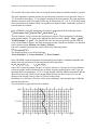
2. The instrument will indicate whether a particular mode allows changing a parameter by showing the word “SET” in the upper left corner of the display. Be careful not to change any
parameter inadvertently.
3. °C°F appear simultaneously, to indicate the sensors’ attenuation in decibels.
4. Values larger than ±1999 or smaller than ±0.01 are displayed in powers of 10±3. As required,
either a “10 3” or “10-3” will appear above and to the right of the displayed value, the value
will be rounded off to 3½ digits. The display will show RNG (out of ranGe), if the number to
be displayed is larger than 1,999,000. Twelve examples follow; for each the number and units
desired to be displayed are shown in italics, depicted immediately below them is the resultant
3½ digit LCD display:
+20 C
+68 F
23,612 ppmV
1104.2
lbs H2O/mmSCF
x10 3
PPM
˚C
DEWPOINT
˚F
DEWPOINT
DEWPOINT
17.688
grams H2O/meters3
DEWPOINT
-100 C
2,000,000
-148 F
˚C
DEWPOINT
G/M3
DEWPOINT
x10 -3
PPM
DEWPOINT
x10 -3
DEWPOINT
˚F
DEWPOINT
0.000,014,75
grams H2O/meters3
0.000,921,15
lbs H2O/mmSCF
0.013,849
ppmV
LBS
0.000,000,1
x10 -3
LBS
DEWPOINT
G/M3
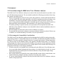
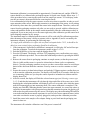
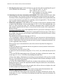
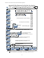
3.4.3 Push Buttons
Four push buttons provide user control of the instrument. They are designated MODE, UP,
DOWN and PRESSURE CORRECT. These push buttons are vertically lined up on the upper left
side of the bare circuit board, with the MODE button on top. There is also a connector provided
which allows the use of external switches. The 8800B makes use of the circuit board mounted
push-button switches, to access them one must open the cover of the 8800B enclosure. The XDTPM is available in several versions:
• With a solid silk screened front face plate, which must be removed to access the circuit board
16
Section 3: Instrument
•
•
switches described above.
With a front face plate which has labeled holes placed immediately above the circuit board
switches, thus the operator may push the switches without removing the face plate, by making
use of a probe such as a paper clip.
With a front plate containing four membrane switches connected to the circuit board, providing the operator with a easy to use interface.
R
S1
C
DEWPOINT TRANSMITTER
US
S2
S3
P
R
S
R
S4
2000
2001
2002
2003
Pushbuttons
DEWPOINT TRANSMITTER
M
O
D
E
MADE IN USA
Remove front plate to access control buttons, consult the manual.
J.F.M.A.M.J.J.A.S.O.N.D
Panel Mounted Instrument with a solid silkscreened face plate
DEWPOINT TRANSMITTER
GND
100-250VAC
50/60HZ
10VA
MODE
ACN
ACH
SIGNAL-IN
SIGNAL-RET
A.OUT
A.RET
TXD
RXD
RET
PS+
NC
NO
C
NC
o
NO
C
o
GND
HI RELAY
LOW RELAY
CAUTION
RELAY
VOLTAGE
UP
DOWN
PRESSURE CORRECT
Bare board, or Instrument opened for access.
Use probe (paper clip) to push control buttons, consult the manual.
Panel Mounted Instrument with a silkscreened face plate with holes
UNITS
VALUES
CHOICES
CHOICES
VALUES
UNITS
P
C RE
O S
R SU
R R
EC E
T
M
O
D
E
DEWPOINT TRANSMITTER
Panel Mounted Instrument with membrane switches
In general the MODE button navigates through the different user options “Modes”; the UP and
DOWN buttons modify the units, values or choices in the selected mode. Refer to the flow diagrams in Appendix A for detailed overview of button functionality. A button may be held down
for a prolonged time, for accelerated incrementing or decrementing of numeric values.
3.4.4 Operating State
Upon power up, the unit performs certain initialization tests (see table in section 3.6), and enters
the ‘Operating State’, in the Viewing Dewpoint mode. Depressing the ‘MODE’ button will
change modes (see appendix A) in the following order: !Viewing Dewpoint "Alarms #Start
Calibration $Viewing Serial Number (back to) !Viewing Dewpoint. The unit will return to
Viewing Dewpoint mode if no buttons are pressed for 30 seconds, unless it is performing a calibration.
3.4.4.1 Viewing Dewpoint Mode
In this mode the user can view the dewpoint, this is indicated by the presence of the ‘DEWPOINT’ legend on the lower left of the display. The available engineering units in which to view
the moisture content are °C, °F, PPM, LBS and G/M3; the UP and DOWN buttons scroll back and
forth through these units in respective order. The °C and °F are dewpoint readings. The PPM is
17
8800 Series Trace Moisture Analyzer Instruction Manual
parts per million by volume computed at the sensor pressure (more about pressure later). The LBS
and G/M3 are density measurements, pounds of water per million standard cubic feet and grams
of water per standard cubic meters, respectively, both in Natural Gas, they are computed according to data derived by IGT Research Bulletin 8, taking into account sensor pressure.
Note that the analog output is linear to the selected engineering units, therefore be mindful that
while scrolling through various units the analog output may change even though the measured
dewpoint is stable.
The PSI legend flashes at the bottom of the display, when there is pressure correction in the computation of the displayed values. A short press of the ‘pressure correct’ button toggles the unit in
and out of pressure correct mode. When there is no pressure correction applied, the PSI legend
does not appear.
Sensor Pressure is used in the context that this is the pressure inside the sample cell when performing the measurement, i.e. it is the operating pressure of the sensor.
Gas Pressure is used in the context that this is the pressure at which the dewpoint is to be calculated.
Pressure Correction is used in the context that the values displayed signify the moisture content at
some pressure (we refer to this as the ‘Gas Pressure’) different from the pressure at the sensor.
Note that PPM, LBS and G/M3 readings are by definition unaffected by pressure correction
because only the pressure at the sensor affects their value. While °C and °F are affected by pressure correction by reporting what the dewpoint would be at the Gas Pressure when the dewpoint
is what is measured at the pressure at the sensor. However, this also implies that whether pressure
correction is applied or not the PPM, LBS and G/M3 readings are affected by the setting of the
sensor pressure.
A long press of the Pressure Correct button, while in the pressure correct mode (flashing PSI legend), changes the unit to the View/Set Sensor Pressure sub-state. The display has the ‘SET’ and
‘PSI’ legends on, and alternately shows SEN and the currently set value for the sensor pressure.
The up and down buttons allow the user to modify the sensor pressure, while a short press of the
pressure correct button toggles the Sensor Pressure setting between whatever value is on the display and 14.7 psi ---- this is a quick way to go back to atmospheric settings. A long press of the
pressure correct button changes the unit back to the Viewing Dewpoint Mode. Pressing the
‘Mode’ button changes the unit to the View/Set Gas Pressure sub-state. The display has the ‘SET’
and ‘PSI’ legends on, and alternately shows GAS and the currently set value for the gas pressure.
The up, down and pressure correct buttons operate in the same manner as in the Sensor Pressure
sub-state. Pressing the ‘Mode’ button changes the unit back to View/Set Sensor Pressure substate, and so forth.
Notes: 1. Instruments are shipped from the factory in the locked mode and must be unlocked
before this procedure can take place (see section 4.3 #7 to unlock).
2. The factory default settings are: 14.7psi for both sensor and gas pressure and pressure
correction disabled.
3. When Pressure correction is disabled all dewpoints are computed by assuming that
both Sensor and Gas Pressures are 14.7psi.
18
Section 3: Instrument
3.4.4.2 Alarms
There are two independent optional alarms, they are named HI and LO alarms. Each alarm can
activate a single pole double throw relay rated at 10A 250VAC or 30VDC per contact. Instruments for use in Division 2 Hazardous Areas have hermetically sealed relays rated at 3A
125VAC. Specially ordered instruments may have a third alarm, refer to the supplied addendum
for relay contact rating, pinouts and user interface issues. The alarms can be set with a trip-point
at any dewpoint within the range of the selected sensor. There is also a selectable hysteresis (with
a minimum value of ±0.5°C to prevent relay chatter) which allows driving systems such as regenerative dryer purge valves in “dewpoint demand mode”. The polarity of the alarm is also selectable, thus one may choose whether the relay energizes above or below the trip point, to allow fail
safe design in case of 8800 Series Trace Moisture Analyzer power loss, or in case of any other
errors or failures which will cause the relays to de-energize.
When an alarm relay is deenergized the corresponding HI and/or LO indicator flashes on the display while viewing the dewpoint.
The behavior of the alarm when a sensor failure (e.g. open or short) is detected is also programmable. The options upon sensor failure are:
1. Fail High - put the alarm in a state as if the dewpoint is high, e.g. A.X.H
2. Fail Low - put the alarm in a state as if the dewpoint is low, e.g. A.X.L
3. Fail Flashing - Energize/Deenergize the relay alternating once every 2 seconds, e.g. A.X.F
4. No Special Handling - if sensor is open the alarm is in a low dewpoint state; if the sensor is
shorted, the alarm is in a high dewpoint state, e.g. A.X.N
Setting or checking the present setup of the alarms is illustrated with the following example:
EXAMPLE : - Set the ‘HI’ alarm to de-energize the relay when the dewpoint wetter than
-75°C with minimal hysteresis (±0.5°C), and faults such as sensor failure cause relays to react as
if there is high dewpoint i.e. if sensor cable breaks the relay de-energizes.
When following these instructions, it may be helpful to refer to Appendix A.
1. Make sure that the instrument is not in the locked mode.
2. While in the viewing ‘Dewpoint Mode’ push the UP or DOWN buttons until the °C indicator appears.
3. Push the MODE button until the display shows:
SET
HI
*
*
the asterisks ‘*’ take the place of characters that may appear depending on previous settings; the ‘SET’ indicator means that changes can be made; the ‘HI’ indicator means that
we are changing the HI Alarm, (alarm #1).
Note that if the instrument does not have the alarm options installed this MODE (User Option)
will not appear.
4. Push the UP or DOWN buttons until the display shows:
SET
HI
the -B means energize below or de-energize above set dewpoint, the H means faults look
like high dewpoint. If the display shows LOC, the alarm changes are locked out, repeat step
1.
19
8800 Series Trace Moisture Analyzer Instruction Manual
5. Push the MODE button. The display will show:
SET
HI
****
˚C
DEWPOINT
the ‘DEWPOINT’ indicator means that we are changing the alarm trigger dewpoint
6. Push the UP or DOWN buttons until the display shows:
SET
HI
˚C
DEWPOINT
7. Push the MODE button. The display will show:
SET
HI
*
˚C
the Z indicates that we are changing the hysteresis of the alarm.
8. Push the UP or DOWN buttons until the display shows:
SET
HI
˚C
9. Push the MODE button until the instrument goes to the dewpoint display mode.
10. If it is desired to prevent inadvertent alarm settings changes by unauthorized people, activate the Lockout.
The instrument will retain the alarm settings even if the power is turned off.
Pressing the MODE button changes to the Start Calibration Mode.
3.4.4.3 Start Calibration
The instrument is calibrated at the factory with the sensor it is shipped with and does not need to
be re-calibrated prior to installation.
The calibration mode allows two different types of calibrations.
• SpanCheck™: an Automatic Calibration using the sensor’s ability to saturate, thus no additional materials or equipment are required, this calibration is most useful after long periods of
usage and a suspicion of performance degradation.
• Single point calibration: the calibration curve derived from SpanCheck is modified at a single
point using the output of the sensor as it is exposed to a gas with a known dewpoint. This calibration is most useful when the sensor is exposed to hygroscopic substances which constantly
alter the equilibrium between the sensor and the gas being measured (e.g. glycol), or when the
sensor is exposed to corrosive gasses and may drift. If the known gas is chosen to be at a dewpoint at or close to the critical measurement point of the process then an extreme accuracy of
the process may be maintained even in the most harsh of applications.
In general we recommend to perform SpanCheck in 12 month intervals (not more often), and single point calibration as often as practically possible. When it is time to perform both calibrations,
then first disable the single point calibration, then perform the SpanCheck calibration, then perform the single point calibration. This procedure is not necessary but it is preferred when both calibration are performed.
3.4.4.3.1 SpanCheck™ Mode
The instrument is calibrated at the factory with the sensor it is shipped with and does not need to
be re-calibrated prior to installation.
20
Section 3: Instrument
Instrument calibration is recommended in approximately 12 month intervals, and the XTR65W
sensor should be re-calibrated after prolonged exposure to liquid water. Simply follow steps 1 - 7
of the procedure below, removing the sensor from the sample gas stream. To avoid injury, make
sure the gas stream is depressurized before removing the sensor.
It is recommended to keep the sensor exposure to room air as short as possible, in order to avoid
super saturation of the sensor. While super saturation is not damaging to the sensor, it will prolong
the initial dry-down time after you install the sensor in the sample stream. Therefore, remove the
sensor from the packaging container only after you are ready to proceed with the calibration procedure and install the sensor in the sample stream immediately after the calibration procedure is
completed. If you are not ready to use the sensor right away after calibration, put the sensor back
in the shipping container for dry storage.
The instrument must be calibrated with the sensor it will be used with.The calibration procedure
takes advantage of the sensor’s ability to saturate (refer to Appendix F) and is executed by the
instrument computer, by performing the following steps:
If a single point calibration is in effect with a reference dewpoint below -70°C, it should be disabled (see next section) before performing SpanCheck calibration.
1. If the instrument is locked and a calibration is attempted; it will display LOC and will not perform the calibration. To unlock the instrument consult section 3.4.5.-10
2. Push the MODE key a few times until the display shows CAL.
3. Press the UP button. The display will show CNF, prompting you to confirm that you want to
start the calibration procedure. You can abort the calibration procedure by pressing the MODE
key.
4. Remove the sensor from its packaging container or sample stream, so that the porous metal
filter is visible and the sensor is exposed to in-hand micro-climate (refer to explanation
below). Close the packaging container as soon as you have removed the sensor to avoid degradation of the desiccant inside the container. You may want to re-use the container at a later
date.
5. Expose the sensor to in-hand microclimate, and push the UP button again to confirm that you
want to start the calibration procedure. The display will flash AC for 60 seconds, while the sensor is saturating. Make sure you keep the sensor exposed to in-hand micro-climate until the
display shows END.
6. After 60 seconds, the display will flash the selected sensor type (see Selecting a sensor type
3.4.5.-2) and then the instrument will calculate the slope and offset of the sensor curve while
displaying the calculations and then will display END for a few seconds, after which the instrument will automatically go into measuring mode. The sensor calibration is completed. (The
display may flash SAT, indicating that the sensor has super-saturated. As soon as the sensor is
exposed to an atmosphere with a dewpoint lower than the saturation dewpoint, the display will
indicate the dewpoint measured by the sensor.) The display may show alternating SEN and 2LO
as an indication that the measured capacitance is too low to be from a saturated sensor, in this
case make sure that the sensor is properly plugged in, and repeat the calibration procedure.
7. Install the sensor in the sample cell or adapter fitting or put it back into the packaging container for later use.
The instrument will retain the calibration even if the power is turned off.
21
8800 Series Trace Moisture Analyzer Instruction Manual
Under certain conditions, an over (super) saturated sensor may need to be completely dried out
before a calibration is performed. Symptoms of these conditions are a sensor that will not go
through the SpanCheck™ function to the END display, or a sensor that will not dry down after calibration. To dry, install sensor in either a known dry gas stream i.e. instrument quality air or dry
nitrogen, or place sensor in a dry can or bottle of desiccant and seal the container from outside air
(the shipping container is designed for this purpose). After a minimum dry out period of 24 hours,
proceed with the calibration procedure of your choice.
SpanCheck™ calibrates sensors by using micro climates. Please contact your representative if
you have any questions about how to create such micro climates.
A perfectly acceptable and accurate for calibration micro-climate may be created for the XTR100
and XTR65 sensors by cupping the sensor in the palm of one’s hand during the SpanCheck™ procedure. Remember that the micro-climate does not have to be accurate, it just has to be higher
than the designed saturation level. The dewpoint of the micro-climate within the fingers is usually
higher than the dewpoint of the room air and probably well above the +20°C upper range of the
sensor. On a dry day, one may need to exhale in the hand before cupping the sensor to guarantee a
high dewpoint. The sensor should be warmed up close to body temperature before performing this
procedure. Care must be taken that the sensor temperature is not below the temperature of the
hand, as in such case condensation could occur and super saturate the sensor. For the same reason,
avoid exhaling directly onto the sensor.
3.4.4.3.2 Single Point Self Calibration, manual or scheduled
The instrument is calibrated at the factory with the sensor it is shipped with and does not need to
be re-calibrated prior to installation.
Single point calibrations should be performed whenever the measurement is in question, or on a
scheduled basis depending on the application. Consult with your representative to establish criteria for specific applications.
The single point calibration is performed on the premise that the sensor is exposed to a gas with a
known dewpoint for a time sufficient to equilibrate. Then the sensor output is measured, and the
calibration curve is adjusted to provide measurement computations which correspond to the
known dewpoint. Measurements over the full sensor range are linearly adjusted to this known
point.
The single point calibration provided by this instrument may be performed manually, or (when a
sample system is ordered equipped with an electrically actuated switchover valve) unattended on
a repetitive timer scheduled basis. The user interface for both is the same, with additional steps for
interval setting and automatic stabilization time outs for the instrument with the electrically actuated valve.
Manual Single Point Self Calibration procedure for instruments without electrically actuated switchover valve:
• Refer to the unshaded area of the flow diagram on the second page of Appendix A.
• Expose the sensor to a known dewpoint
• Wait at least 15 minutes for the sample system to be stable, if the known gas is of a low dewpoint the waiting time may have to be increased - specially if the sensor was wet before the
procedure is initiated. Consult with your representative to determine sufficient waiting time
for your application.
22
Section 3: Instrument
•
•
•
•
•
•
•
•
Make sure the instrument is unlocked.
Press the MODE button a few times until the display shows CAL.
Press the DOWN button to select the Self Calibration mode. The display will show SLF/CAL
Press the DOWN button to confirm entry into the Self Calibration mode. The display will
show the reference dewpoint which has been previously programed into the instrument, the
SET and DEWPOINT legends will also appear. Use the UP and DOWN buttons to modify
this dewpoint to match the dewpoint of the known gas to which the sensor is exposed.
Press the MODE button, the display will show BEG/S.C., prompting to begin the Self Calibration.
If the MODE button is pressed the calibration will be canceled and instrument will go to the
Serial Number mode. All setup will still be in effect, e.i. newly entered reference dewpoint
will remain in the instrument’s memory.
If the DOWN button is pressed the Self Calibration corrections will be disabled; any Self Calibrations performed previously will not be used in correcting the computed dewpoint of the
instrument.
Press the UP button to initiate the Self Calibration. the display will show CNF/SC?, prompting
for a confirmation that the Self Calibration should be performed.
If the DOWN or Pressure Correct buttons are pressed the Self Calibration will be aborted.
Press the UP button to confirm the Self Calibration. The display will show alternately S.C./
STB /-41.5, indicating that Self Cal Stabilization is being checked and currently the instrument is measuring -41.5°C. When the measured dewpoint is stable within 0.5°C for 3 minutes
the instrument will record the new single point self calibration values and finish by going to
the display dewpoint mode. Note that the program will spend atleast 3 minutes on this stage of
the calibration.
The sensor may now be exposed to the sample gas and the instrument will display the measurement using the newly acquired calibration values.
Scheduled Timer Activated Single Point Self Calibration procedure for instruments with
electrically actuated switchover valve and on-board battery backed real-time clock:
• Make sure that your sample system is properly connected according to the sample system
instructions. When the timeouts and stabilization times are summed from the calibration
stages below, it can be determined that the calibration reference gas will be used for atleast 21
minutes, the user should make sure that there is sufficient amount of gas available. If the reference gas is provided from a compressed gas bottle, make sure that there is sufficient pressure
in the bottle, for some bottles there is a cut-off pressure below which the dewpoint is not guaranteed. Make a note of the exact dewpoint of the reference gas as it will be required in the next
steps.
• Refer to the unshaded area of the flow diagram on the second page of Appendix A.
• Make sure the instrument is unlocked.
• Press the MODE button a few times until the display shows CAL.
• Press the DOWN button to select the Self Calibration mode. The display will show SLF/CAL
• Press the DOWN button to confirm entry into the Self Calibration mode. The display will
show the reference dewpoint which has been previously programed into the instrument, the
SET and DEWPOINT legends will also appear. Use the UP and DOWN buttons to modify
this dewpoint to match the dewpoint of the reference gas.
• Press the MODE button, the display will alternately show 720 / HRS / INTR, indicating that
23
8800 Series Trace Moisture Analyzer Instruction Manual
•
•
•
•
•
•
the calibrations are scheduled at 720 hours interval. Use the UP and DOWN buttons to change
the interval time to whatever is determined to be most effective for your application, consult
with your representative if you are in doubt. An interval of 0 Hrs (appears as a blank on the
display), disables any further scheduled unattended calibrations, however the instrument will
continue to make use of calibration values acquired previously or manually in the future.
Pressing the Pressure Correct button will cause the instrument to momentarily display 150 /
HRS / LEFT, indicating that there are 150 hours left until the next scheduled calibration is performed. This is a useful indication in cases where it is not known when the next calibration
will be performed.
Press the MODE button, the display will show BEG/S.C., prompting to begin the Self Calibration.
- If the MODE button is pressed the calibration procedure will be canceled and instrument
will go to the Serial Number mode. All setup will still be in effect, e.i. newly entered reference
dewpoints, the scheduled interval time etc. will still be used by the system.
- If the DOWN button is pressed the Self Calibration corrections will be disabled; any Self
Calibrations performed previously will not be used in correcting the computed dewpoint of
the instrument. However newly entered reference dewpoints and the scheduled interval time
will still be in effect; thus when the time elapses a Self Calibration will be performed and its
values will be used in correcting the computed dewpoint from that time on.
Press the UP button to initiate the Self Calibration. the display will show CNF/SC?, prompting
for a confirmation that the Self Calibration should be performed.
If the DOWN or Pressure Correct buttons are pressed the Self Calibration will be aborted,
however everything set until now will remain in effect.
Press the UP button to confirm the Self Calibration. The display will show SLF/CAL/-41.5
indicating that self calibration has started and it is measuring a dewpoint of -41.5°C, (this is
also the entry place into the procedure when the scheduled time elapses). Now the instrument
will “freeze” the analog output and the alarm relays so that they are not influenced by the reference gas dewpoint. Then the instrument will activate the electrically actuated switchover
valve and thus introduce the reference gas to the sensor, and initiate a 15 minute time out
allowing the system to reach equilibrium. (Since the program will perform the above when the
scheduled interval elapses, this step may be occurring in an unattended mode, thus the reference gas bottle and regulator must be left in the open positions, the switchover valve will keep
them from being exhausted.)
After the 15 minute stabilization time out, the display will show alternately S.C./STB /-41.5,
indicating that Self Cal Stabilization is being checked and currently the instrument is measuring -41.5°C. When the measured dewpoint is stable within 0.5°C for 3 minutes the instrument
will record the new single point self calibration values. Note that the program will spend at
least 3 minutes on this stage of the calibration.
The electrically actuated switchover valve will be deactivated thus introducing the sample gas
to the sensor, and the dewpoint will be monitored for stability. The display will show S.C./
FIN/-42 indicating that self calibration has finished and it is measuring a dewpoint of -42°C.
When the measured dewpoint is stable within 0.5°C for 3 minutes the instrument will
“unfreeze” the analog output and relays and go to the display dewpoint mode.
The instrument will display the measurement using the newly acquired calibration values.
The instrument computes the dewpoint from the measured capacitance of the sensor. The
24
Section 3: Instrument
sequence of computations is as follows:
• The capacitance is converted to percent of full scale (-100°C to +20°C dp), using the low dB,
low dew, and saturated dB when performing SpanCheck values.
• Cal Adj is applied to correct the mid point of the curve.
• If enabled, the multi-point calibration table is applied to further correct the transfer function.
• If enabled, the single point calibration is applied to fine tune the transfer function.
• The corrected percent of full scale is converted to dewpoint.
3.4.4.4 Viewing Serial Number Mode
In this mode the user can view the instrument serial number. The display shows the serial number
by alternately displaying XSN and the number. If the number is larger than 1999 then it is displayed in 2 parts, first part is the thousands signified by the x103 legend in the upper right corner
of the display and the second part is the units. For example serial number 12345 will be shown as:
Pressing the UP and DOWN buttons simultaneously resets the instrument, this is useful in installations where power can not be turned on and off easily. Pressing the Pressure Correct button will
cause the instrument to enter the setup state.
Pressing the MODE button, returns the unit to the Viewing Dewpoint Mode.
3.4.5 SetUp State
To enter the Setup State power-up the unit (or reset it from the serial number Mode), and hold the
MODE key pressed while the unit is initializing. Refer to Appendix B for a flow diagram of the
SetUp State.
The setup state provides eleven capabilities, each one controlled from its own mode. Depressing
the MODE button navigates through the modes in the following order: !Select Alternate Display
Units "Select Sensor Type #Set Measured Attenuation of Sensor at a Low Dewpoint $Set the
Low Dewpoint at which the Attenuation was measured %Set the Calibration Mid-range Adjust
&Analog Output select 4/20mA or 0/24mA 'Perform a Test and Verification of the Analog Output (Set dewpoint corresponding to low end of Analog Output )Set dewpoint corresponding to
high end of Analog Output *Lock/Unlock the instrument !!Sensor Cable Compensation
(back to) !.
These eleven functions are explained in their respective sections which follow. Note that modes
6,7,8&9 will appear only on instruments with the analog output option. Changes can be made
only to an unlocked instrument, the changes are stored (when the MODE button is pressed) and
retained even if the instrument power is turned off.
1. Display of alternate units: In this mode, a second engineering unit can be chosen to be displayed alternating with the engineering unit selected in the operating state, for example, a
dewpoint can be alternately shown in °C and in PPM.
CAUTION:
2), 3), 4) and 5) are set at the factory and need only be modified when a sensor is changed.
25
8800 Series Trace Moisture Analyzer Instruction Manual
2. Selecting the sensor type: In this mode the user can select the software matching the type of
sensor installed in the instrument:
XT1 : XTR-100 (-100°C to +20°C);
XT6 : XTR-65 (-65°C to +20°C);
DB : show impedance of any sensor, disable
Open and Short error massages.
3&4Adjusting low end sensor attenuation and dewpoint: These modes are used to enter a data
pair representing a low dewpoint and the sensor attenuation measured at this low dewpoint.
(see Sensor Theory of Operation appendix F). This data pair should not be modified unless the
sensor is replaced (refer to procedures for replacing a sensor in appaendix L). The sensor shipping container is labeled with the proper values.
5. Calibration Adjustment: In this mode the user can enter a sensor specific Adjustment Value
to improve the instruments’ accuracy in the range of -50°C to -10°C, this adjustment has very
little or no effect outside this range. The Calibration Adjustment Value is printed on the shipping container supplied with the sensor, or may be derived if the sensor can be exposed to a
known reference.
Deriving an Adjustment Value: If the adjustment value for your sensor is not known, contact
your representative and follow the instructions in paragraph B on the next page. If the value is
not available, then it may be derived using a manual method, provided that a moisture calibration facility is available.
The calibration must be done in the range of -25°C to
-20°C (attempting to calibrate outside this range may cause inaccuracies), the dewpoint must
be kept stable during calibration and it must be measured accurately by a reference instrument
such as a chilled mirror. One must also note the state of pressure compensation and turn it on
or off as applicable to the reference.
The necessary steps are described below (also refer to the Set-Up State flow diagram in
Appendix B):
a. Make sure that the low attenuation and low dewpoint are correctly entered for this sensor.
b. SpanCheck™ the sensor.
c. Dry-down the sensor for at least 12 hrs.
d. Expose the sensor to the known dewpoint (-25°C to -20°C), for a sufficient time (at least 30
min.)
e. Go to the CAL/ADJ mode and press the UP button, the display will show the current value,
in the range of -1.99 to +1.99 followed by blinking horizontal lines.
f. Observe the display, if the buttons are not being pressed; the display will every few seconds
show for a short duration the dewpoint as being computed at the moment (utilizing the current
cal-adjust value in the computation).
g. Use the UP or DOWN buttons to modify the cal-adjust value and observe the alternately
displayed dewpoint. Perform this adjustment until the dewpoint matches the value shown by
the reference instrument.
h. Press the MODE button to go to the next mode, this will save the new cal-adjust value, and
it will be retained even if power is turned off.
Entering a known Adjustment Value: If the sensor is being replaced an adjustment value
should be supplied with the sensor, to enter it into the instrument:
a. Go to the CAL/ADJ mode and press the UP button, the display will show the current value,
in the range of -1.99 to +1.99 followed by blinking horizontal lines, ignore the alternately displayed dewpoint.
26
Section 3: Instrument
b. Use the UP or DOWN buttons to modify the cal-adjust value as necessary.
c. Press the MODE button to go to the next mode, this will save the new cal-adjust value, and
it will be retained even if power is turned off.
6. Analog Output Span selection 4/20 mA or 0/24 mA: By pushing the UP or DOWN buttons,
the user may select the desired span of the analog output.
7. Testing the analog output: By pushing the UP, DOWN, or Pressure Correct buttons, the user
forces the analog output to its high, low and mid-range values, respectively. This facilitates
the hook-up and testing of the user’s monitoring equipment.
8&9Output range setting: These modes are used to set dewpoints corresponding to the low and/
or high end of the Analog Output. The factory default values are: low end at -100°C, and high
end at +20°C. For detailed discussion of the necessary considerations when choosing the analog output range, refer to appendix J.
10. Lock/Unlock the instrument with optional SECURED password protection
The Lock/Unlock feature of the instrument allows the owner to block access to parameter settings, protecting the instrument from unauthorized or inadvertent changes. Attempting to
change settings while the instrument is locked will display LOC and beep.
•
When in the Lock/Unlock Mode and the instrument is locked the display will show “SET LOC”.
The instrument may be unlocked by pressing the “UP” button. If “SEC” is displayed, refer to
the Secured Password Protection section below.
• When the instrument is unlocked the display will show “SET UN/LOC”. The slash (/) denotes
that the display is alternately showing UN and LOC, this is necessitated by the 3.5 digit limitation of the display. Pressing the “DOWN” button will lock the instrument.
• Pressing and holding either the “UP” or “DOWN” buttons, will save the locked or unlocked
setting depending on the button, and reset the instrument. This feature is useful in situations
where it is difficult or undesirable to power off the instrument.
• Pressing the MODE button will navigate to the Sensor Cable Compensation mode.
Secured Password Protection
Instruments may be specially ordered with password protection. To unlock the instrument the user
must supply a password, which consists of a number in the range of -1999 to 1999 (approximately
4000 unique passwords). Instruments that require a password, will display “SEC” (secured) when
the user attempts to unlock by pressing the “UP” button. After approximately 1 to 2 seconds the
instrument will display “000”, with the first digit flashing. The flashing denotes the cursor position, which means that the “UP” and “DOWN” buttons will increment or decrement this digit
respectively. Pressing the “MODE” button will move the cursor (flashing digit) to the right. Pressing and holding the “MODE” button will signal the instrument to read the password and if correct
to unlock the instrument. As discussed above an unlocked instrument will display “SET UN/LOC”.
The user may enter the assigned password by pressing the UP, DOWN and MODE buttons. The
first digit is unique in that it consists of 1½ digits in the range of -19 to 19, this allows entering the
full range of assignable numbers.
An example is used to illustrate the unlocking of a password-protected instrument. Suppose the
password is 1234. After an attempt to unlock, the user will see “SEC” followed by “000”, with the
first 0 flashing. Pressing the “UP” button twelve times will display “1200” (overshooting a number can be corrected by reversing the use of the UP and DOWN keys), with the “12” flashing.
Pressing the “MODE” button will flash the next “0”. Pressing the “UP” button three times will
display “1230”. Pressing the “MODE” button will flash the last “0”. Pressing the “UP” button
27
8800 Series Trace Moisture Analyzer Instruction Manual
four times will display “1234”. Pressing and holding the “MODE” button, will display “SET UN/
LOC”, indicating that the instrument is now unlocked. It may be locked without the password,
same as any other instrument.
Note: To avoid unauthorized changes, it is imperative that instrument is returned into the locked
mode.
11. Sensor Cable Compensation: As noted in other paragraphs this instrument measures the
impedance of the sensor (in the form of attenuation in decibels) from which it computes the
dewpoint. At very low dewpoints the sensor capacitance is small enough to be in the same
order of magnitude as a long coaxial cable. Thus the measurement circuit must be compensated for the impedance of the sensor cable. Instruments which are delivered with a cable
are already compensated at the factory and should not be compensated again, however if
a new cable is connected, the following procedure should be used for compensation (also refer
to the Set-Up State flow diagram in Appendix A):
a. Disconnect the sensor from the cable by unplugging the BNC connector, keep the cable
connected to the instrument.
b. Prepare a means by which the BNC connector at the end of the cable could be reliably
shorted (using a jumper clip etc.), do not attempt to short at the instrument screw terminals as
this approach will not account for the cable resistance.
c. Go to the CNF/CBL/OPN (Confirm Cable Open) mode.
d. Leave the BNC connector open and press the UP key. The instrument will show OPN and
beep for a few seconds. Then it will show CNF/CBL/SHR (Confirm Cable Short).
e. Short the BNC connector and press the UP key, the unit will show SHR and beep for a few
seconds. Then it will show CNF/CBL/OPN again.
f. Leave the BNC connector open again and press the UP button. The instrument will show
OPN and beep for a few seconds. Then it will show END
The compensation data will be retained even if power is turned off.
3.5 Resetable Audio-Visual Alarm Option (NFPA compliant)
When the instrument is ordered with an Audio-Visual Alarm option, it is provided in the 8800B
enclosure, outfitted with two front panel momentary push buttons in NEMA sealed rubber boots.
The instrument complies with the recommendations of NFPA 99, 1996 edition.
• The alarm set point is programmed on a third alarm, hence the HI and LO alarm relays are free
to be used for additional purposes The third alarm is properly configured to 39°F at the factory, but when necessary may be modified by the user. Refer to the notes following HI & LO
Alarms in the Flow Diagram of Operating State User Interface in appendix A.
• The visual indicator is the display backlight. When there is no alarm condition the LCD display is not backlit but can still be easily and clearly read (in an extremely dark room the backlight may be momentarily turned on by pressing the TEST button). However as long as an
alarm condition exists the LCD will be backlit in red. This lit-up front window of the instrument is the visual indicator.
• This configuration is also equipped with a NEMA sealed audio indicator (>80dB @ 3ft)
mounted in the instrument enclosure. It is activated when an alarm condition occurs, it may be
disabled by momentarily pressing the RESET button on the front panel. When the alarm con-
28
Section 3: Instrument
•
dition ceases to exist, the audio indicator is automatically re-enabled, ready to be activated on
next alarm condition.
A momentary TEST button on the front panel allows testing both the visual and audible indicators.
3.6 Troubleshooting the Instrument
This instrument performs diagnostic tests on power up as well as once every two minutes. The
table that follows, depicts all possible error/unexpected messages that may be displayed on the
instrument. For each message the table has explanations for the reason, and if necessary a suggested action to remedy it.
The instrument contains a fuse which may open if the instrument is subjected to voltages exceeding the specifications. Under these circumstances the unit display will be blank and the instrument
will not draw any current when powered up. The user may replace the fuse with a comparable
0.5A, 250V fast acting fuse, to locate the fuse refer to the 8800 Series Trace Moisture Analyzer
mechanical drawing in Appendix E.
29
8800 Series Trace Moisture Analyzer Instruction Manual
DISPLAY
EXPLANATION
REQUIRED ACTION
+
PROM check sum failed.
HI ERR
+
RAM write/read test failed.
% ERR
+
Unidentified power-up failure.
C.S.F/
+
EEPROM Check Sum Failed.
return to your representative
ERR/AD
+
A/D converter failure.
for service.
ERR/REF
+
Reference voltage for A/D out of spec.
LO/BAT
+
Low supply voltage.
LO RNG/
TEMP
+
Instrument low temperature range
has been exceeded.
HI RNG/
TEMP
+
Instrument high temperature range
has been exceeded.
OPN/
+
Sensor circuit is open.
SAT/
+
Sensor is saturated.
SHR/
+
Sensor circuit is shorted.
+
Trying to calibrate an undefined sensor.
SEN/2LO
+
Sensor reading is ‘too’ low to be from a saturated sensor,
thus can not be calibrated
While Compensating for cable length, the measurement did not
correspond to the expected open or short values.
2LO
2HI
dewpoint display
tests
calibration
tests
DB
cable
tests
Trying to calculate dewpoint for undefined sensor.
...
system tests once per 2 min.
power on tests
LO ERR
cycle power
if problem persists,
make sure that the unit is at a
temperature of -10°C to +50°C.
see table in sensor troubleshooting section 2.5
select sensor and recalibrate.
see calibration instructions.
Check the means of opening & shorting the sensor
cable. see section 3.4.5 - 11
ERR/EEP
+
EEPROM write cycle not completed.
if this persists, return for service.
LOC
+
Attempting to modify a locked unit.
unlock unit, see set-up state 3.4.5.-10.
SEC
+
Attempting to unlock a secured unit.
The HI Alarm (alarm #1) relay is deenergized.
LO (flashing while
viewing DEWPOINT)
The LO Alarm (alarm #2) relay is deenergized.
+
A.O./OPN
The Analog Output ‘sees’ an open circuit
PSI flashing when displaying dewpoint
Pressure correction is enabled, the dewpoint is computed using
programmed pressures
-70°C (-94°F) with
flashing DEWPOINT
An XTR-65 sensor is measuring less than -70°C or -94°F D.P.
check the cables connecting the analog output, make
sure the terminating impedance is less that 500Ω.
refer to section 3.4.4.1
check instrument
upgrade to XTR-100 sensor
number can not be displayed in 3½ digits
RNG
+
XEN
display is dark
Legend: +
/
See section 3.4.4.2 Setting the Alarms.
miscellaneous
HI (flashing while
viewing DEWPOINT)
Turn on message, Xen (Greek Ξ=X)
No power to instrument
check power to instrument, check fuse
denotes a beeping accompaniment to the message.
denotes alternately flashing messages.
30
Section 3: Instrument
3.7 Maintenance
The 8800A and 8800B instrument enclosures may be cleaned when necessary using a damp
(moist) cloth. The sensor should not be cleaned as it may be damaged.
Spare parts may be ordered through your representative.
31
8800 Series Trace Moisture Analyzer Instruction Manual
32
Glossary
Glossary
0/24 mA . . . . . . . . . . . . . . . . range of current for the current loop [0mA=minimum reading,
24mA=maximum reading]
4/20 mA . . . . . . . . . . . . . . . . range of current for the current loop [4mA=minimum reading,
20mA=maximum reading] - preferred because less than 4mA can
indicate a fault or open circuit, also there is at least 4mA available
to power equipment
7 segment . . . . . . . . . . . . . . . type of display configuration - where 7 segments can be used to
form the numbers 0 through 9 and most letters
A/D . . . . . . . . . . . . . . . . . . . . analog to digital - a device or circuit that converts an analog voltage
to a digital number
absorption . . . . . . . . . . . . . . . retention by penetration into bulk of material
adsorption . . . . . . . . . . . . . . . retention as a surface layer on a material
accuracy . . . . . . . . . . . . . . . . quantification of the magnitude of error of a measurement, or
degree of conformity with a standard.
Al2O3 . . . . . . . . . . . . . . . . . . aluminum oxide
attenuation. . . . . . . . . . . . . . . the decrease in intensity of a signal, as a result of absorption of
energy, measured in decibels (dB).
AWG . . . . . . . . . . . . . . . . . . . American Wire Gauge [size of the wire, cross section area of the
wire]
baud. . . . . . . . . . . . . . . . . . . . Bits per second of data transfer [over the serial interface]
bit[s] . . . . . . . . . . . . . . . . . . . Binary digit[s] - ones and zeros
BNC . . . . . . . . . . . . . . . . . . . a connector type, used with coaxial cables
bypass mounting . . . . . . . . . . sensor mounting in a slip stream of sample, which feeds back into
the process stream
CE . . . . . . . . . . . . . . . . . . . . . Conformitée Europeane; symbol affixed to a product indicating its
conformance with directives issued by the European Community
(EC)
CENELEC . . . . . . . . . . . . . . Comité Europeen de Normalisation Electrotechnique (European
Committee for Electrotechnical Standardization); amongst many
others has set standards for intrinsic safety
check sum . . . . . . . . . . . . . . . an arithmetic total on a set of data: e.g. the data in the instrument's
memory is summed and compared to previous sums checking for
corrupted data
coalescing . . . . . . . . . . . . . . . formation of liquids in gas samples, or separation and collection for
disposal of liquids from gas samples
control drawing . . . . . . . . . . . schematics and system drawing of hazardous area approved apparatus with control number issued by approval agency
CSA. . . . . . . . . . . . . . . . . . . . Canadian Standards Association
CTS . . . . . . . . . . . . . . . . . . . . Clear To Send - a label for a RS232 interface control line
cUL . . . . . . . . . . . . . . . . . . . . indicates UL evaluation of a product to Canadian safety requirements
current loop . . . . . . . . . . . . . . a circuit where the variation in the current flow is used to indicate
the value of a measurement from the instrument, only 2 wires are
33
Manual
used for the circuit [see 4/20]
dB . . . . . . . . . . . . . . . . . . . . . see - decibel
DB25 . . . . . . . . . . . . . . . . . . . a style and size of connector - in this case with 25 pins
DB9. . . . . . . . . . . . . . . . . . . . a style and size of connector - in this case with 9 pins
decibel . . . . . . . . . . . . . . . . . . a dimensionless unit representing the logarithm of the ratio of two
values
DEMKO . . . . . . . . . . . . . . . . independent test laboratory and the European National Certification
Body for Denmark for the safety testing of electrical products
desiccant . . . . . . . . . . . . . . . . drying agent, usually made from molecular sieve, silica gel or activated alumina
desorption . . . . . . . . . . . . . . . release of a previously absorbed or adsorbed substance
dewpoint . . . . . . . . . . . . . . . . saturation temperature of a gas in regards to another gas
dewpoint demand mode . . . . scheme to control the switching between the desiccant towers of a
dryer based on the actual dewpoint
dielectric constant . . . . . . . . . measure of the ability of a material to hold an electric charge when
placed between two metal plates, most commonly measured relative to that of free space
Div 2 . . . . . . . . . . . . . . . . . . . see Division 2 Hazardous Areas
Division 2
Hazardous Areas . . . . . . . areas classified as hazardous under abnormal conditions (0.1-10
hrs/year)
DSR. . . . . . . . . . . . . . . . . . . . Data Set Ready - a label for a RS232 interface control line
DTR . . . . . . . . . . . . . . . . . . . Data Terminal Ready - a label for a RS232 control line
EEPROM . . . . . . . . . . . . . . . Electrically Erasable Programmable Read Only Memory - a device
that can remember information, even when it has no power applied
to it
electromagnetic
compatibility . . . . . . . . . . compatibility with directives issued under CE or with FCC standards, concerning electromagnetic interference
EMI . . . . . . . . . . . . . . . . . . . . Electro-Magnetic Interference - external electrical or magnetic signals from natural or man-made sources that can interfere with a
device
3 . . . . . . . . . . . . . . . . . . . see - grams per cubic meter
G/M
grams per cubic meter. . . . . . the mass of water vapor present in unit volume of moist air at standard temperature and pressure.
HTF™ . . . . . . . . . . . . . . . . . Hyper-Thin-Film aluminum oxide sensor technology.
hygrometer . . . . . . . . . . . . . . device measuring the amount of water present in a sample
hygroscopic . . . . . . . . . . . . . . property of attracting water or water vapor
hysteresis. . . . . . . . . . . . . . . . lagging in effect behind it’s cause depending upon whether the condition is approached from above or below the value of interest; purposefully programmed into control systems with relays to avoid
chatter
IGT Research Bulletin 8 . . . . Institute of Gas Technology, has developed Charts of the Equilibrium Moisture Content of Natural Gases in the Range of -40°F to
250°F and 14.7 to 5000 psi
34
Glossary
impedance . . . . . . . . . . . . . . . the ratio of voltage to current at a specified frequency measured in
Ohms, a resistor of the same value would act the same as the measured circuit
in-situ . . . . . . . . . . . . . . . . . . measurement with sensor located in the process stream
intrinsically safe . . . . . . . . . . incapable of releasing enough electrical or thermal energy to cause
the ignition of flammable substances listed for a hazardous area
classification
LBS H2O/mmscf. . . . . . . . . . see - pounds of water per million standard cubic feet
LCD . . . . . . . . . . . . . . . . . . . Liquid Crystal Display - a display that uses a special material [that
is sensitive to electrical voltages] to affect the transmission or
reflection of light
monograph . . . . . . . . . . . . . . a systematic learned exposition of a subject, e.g. a chart representing dewpoint conversions for differing pressures.
National Electrical Code . . . . a set of US standards related to accepted practices for electrical wiring
NFPA. . . . . . . . . . . . . . . . . . . National Fire Protection Agency (issuer of the National Electrical
Code (NEC))
NIST . . . . . . . . . . . . . . . . . . . National Institute of Standards and Technology
NPT . . . . . . . . . . . . . . . . . . . . National (American Standard) Pipe Taper; an ASTM (American
Society for Testing and Materials) standard of tube fittings with
tapered threads
parity . . . . . . . . . . . . . . . . . . . a way of incorporating error checking into a RS232 data transmission [on a character by character basis] to check if the data has been
received correctly
pounds of water per
million standard cubic feet . (LBS H2O/mmscf) the mass of water vapor present in unit volume
of moist air at standard temperature and pressure.
a measurement unit for moisture, typically used in the natural gas
industry
ppm . . . . . . . . . . . . . . . . . . . . parts per million - usually based on volume measure, but must be
stated whether it is by volume or by mass (weight)
ppmV . . . . . . . . . . . . . . . . . . parts per million based on volume measure, volume of water vapor
per total volume of gas for an ideal gas.
pressure correction . . . . . . . . computation of dewpoint at a pressure different from the pressure at
the sensor
PROM . . . . . . . . . . . . . . . . . . Programmable Read Only Memory - a device that can be programmed so that data is permanently stored in it [typically used for
computer programs]
RAM . . . . . . . . . . . . . . . . . . . Random Access Memory - a device that holds data as long as it has
power applied to it [the data can be changed with out limit]
regenerative dryer purge . . . . small flow of dry air from drying column passing through regenerating column and desorbing water from desiccant at low pressure
response time . . . . . . . . . . . . time it takes for a sensor to react to change in its environment
RG58 . . . . . . . . . . . . . . . . . . . a type of coaxial cable - the letters/numbers refer to the electrical
characteristic of the cable [resistance/capacitance per foot of
length]
35
Manual
RG6 . . . . . . . . . . . . . . . . . . . . A type of coaxial cable - the letters/numbers refer to the electrical
characteristic of the cable [resistance/capacitance per foot of
length]
RS-232C . . . . . . . . . . . . . . . . a specification for electrical signaling [also referred to as RS232]
that describes the voltages, rate of change of the voltages, and the
signal names and uses for the signals
RTS . . . . . . . . . . . . . . . . . . . . Request To Send - a label for a RS232 interface control line
sample system . . . . . . . . . . . . equipment used to bring conditioned sample to the sensing element;
it may include regulators, filters, heaters/coolers, flow meters,
valves and other accessories.
saturate . . . . . . . . . . . . . . . . . reaching maximum holding capacity
sintered . . . . . . . . . . . . . . . . . produced by a process of compacting and heating metal powder,
resulting in the formation of a solid, permeable object.
slip stream . . . . . . . . . . . . . . . partial stream extracted from a process stream, of which it is representative
SpanCheck™ . . . . . . . . . . . . method to check the response of an HTF™ sensor at the upper end
of its measurement range
stability . . . . . . . . . . . . . . . . . a measurement's degree of insensitivity to disturbances.
UL . . . . . . . . . . . . . . . . . . . . . Underwriters Laboratories Inc., an organization which evaluates,
tests and certifies products for specific safety situations.
uncertainty . . . . . . . . . . . . . . quantification of the error that can be expected from a measurement, characterizing the range in which the true value can be
expected to be in.
36
8800 Series Trace Moisture Analyzer Instruction Manual Appendices
Appendix A: Flow Diagram of Operating State User Interface
30 seconds anywhere (other than
"Calibration") without key press
Power ON initialization
and sign on message
appears when changing
settings of locked unit
Toggle Pressure Correction
HI/LO
˚C
PSI
1/2 sec
Viewing Dewpoint
Flashing PSI indicates
pressure corrected
dewpoint
{
Flashing HI and/or LO
indicates corresponding
relays not energized
DEWPOINT
units
SHORT PRESS
LONG PRESS
AND PSI MODE
SET
HI
Toggle 14.7 psi
VALUE
{
PSI
{
choices
SET
HI
˚C
DEWPOINT
View/Set
Sensor
Pressure
SHORT PRESS
values
Set trigger dewpoint
LONG PRESS
{
values
SET
HI
˚C
Toggle 14.7 psi
SET
VALUE
{
{
PSI
values
View/Set
Gas
Pressure
SHORT PRESS
LONG PRESS
values
SET
LO
Cancel Calibration (it is not performed)
Setting HI Alarm (Relay 1)
SET
Set hysteresis
{
Set activity options
Relay polarity:
= energize relay above trigger dewpoint
= energize relay below trigger dewpoint
appropriate polarity selection in conjunction with
proper wiring wll provide fail safe operation
choices
SET
LO
˚C
DEWPOINT
Set trigger dewpoint
{
Scroll through Alarm activity options
Fault reaction:
= faults do Not effect relays
= faults "look" like High dewpoint
= faults "look" like Low dewpoint
= faults Flash the relay
values
SET
LO
˚C
Set hysteresis
{
Setting LO Alarm (Relay 2)
Displayed only if alarm options are installed
Set activity options
values
When a third Alarm Relay is installed,
setup menu options will appear here
similar to Relays 1&2, but with both
the HI&LO legends active. This is
also the dewpoint alarm for units with
resetable Audio-Visual Alarm.
Start
Calibration
few sec
SET
NUMBERS
CALCULATING
CALIBRATION
SET
Sensor
Reading
OK
TOO LOW
see Self-Cal user
interface next page
Confirm
SpanCheck
again
{
SET
Confirm SpanCheck
SET
1 sec
go to
Set-Up
State
Press together
to RESET the
instrument
SET
SET
1 minute
New calibration
values are saved
{
Viewing
Serialnumber
ignore error
Legend: A slash ' ' in the display area, is used to depict two alternately shown (flashing back and forth) messages.
denotes beeping. Buttons without designator or arrow leading out, perform no function
37
8800 Series Trace Moisture Analyzer Instruction Manual Appendices
Flow Diagram Operating State User Interface (continued) Manual & Scheduled Self Calibration
Flow diagram items not related to Self Calibration are shaded in gray.
30 seconds anywhere (other than
"Calibration") without key press
Power ON initialization
and sign on message
appears when changing
settings of locked unit
Toggle Pressure Correction
HI/LO
˚C
PSI
{
Flashing HI and/or LO
indicates corresponding
relays not energized
DEWPOINT
1/2 sec
Viewing Dewpoint
Flashing PSI indicates
pressure corrected
dewpoint
SHORT PRESS
units
Confirm Entry into
Self Cal Menus
cancel
SET
Set Reference
Gas dewpoint
˚C
{
DEWPOINT
timeout
values +/-0.1˚C
SET
Set Scheduled Calibration
Interval in hours
View Hours left until
next Scheduled
Calibration
0 (blank)=Scheduled SelfCal disabled,
but SelfCal corrections not affected
{
values +/-1hr.
timeout
SET
The Self Cal Corrections
will not be used in dew
computations from now on,
until another Self Cal is
performed, manually or
scheduled. Schedules
are not affected.
Begin Self Cal Now
disable Self Cal corrections
cancel
{
Confirm performing
Self Cal NOW
Scheduled Time Elapsed,
Entry Point
During Self Cal the Analog output and Alarm Relays are frozen to their previous states
˚C
˚C
DEWPOINT
DEWPOINT
dew is stable
perform
Self Cal
Start
Calibration
Dewpoint stable testing,
Electric Valve Activation, and
15 min. time out for system stabilization, 0.5˚C for 3 min. Displays
performed only if electric valve is installed.
dewpoint being measured now.
Displays dewpoint being measured now.
SET
few sec
SET
NUMBERS
CALCULATING
CALIBRATION
˚C
DEWPOINT
Electric Valve Deactivation, and final
Dewpoint stable testing, 0.5˚C for 3 min.
performed only if electric valve is installed.
Displays dewpoint being measured now.
SET
Sensor
Reading
OK
Self Cal
Completed go to
display Dewpoint
abort performing Self Cal Now
Cancel Calibration (it is not performed)
SET
TOO LOW
Confirm
SpanCheck
again
{
Appears only if
unit is equipped
with electric valve
When ALARM OPTIONS are installed menus appear here
SET
Confirm SpanCheck
SET
1 sec
go to
Set-Up
State
Press together
to RESET the
instrument
SET
SET
1 minute
New calibration
values are saved
{
Viewing
Serialnumber
ignore error
Legend: A slash ' ' in the display area, is used to depict two alternately shown (flashing back and forth) messages.
denotes beeping. Buttons without designator or arrow leading out, perform no function
38
8800 Series Trace Moisture Analyzer Instruction Manual Appendices
Appendix B: Flow Diagram of Set-Up State User Interface
Power-Up with
MODE
key depressed
Power ON initialization
and sign on message
appears when changing
settings of locked unit
4 min anywhere without
key press
go to
Operating
State
Choose alternate units to show when displaying dewpoint.
SET
blank
F
C
ppm
LBS
G/m3
PSI
%
CF
Temp F
Temp C
{
Factory default is blank, (there is no alternate display).
Choose sensor type
measure
attenuation of
sensor
XTR-65
{
XTR-100
sensor type
SET
Lo
Set measured attenuation at a known low dewpoint
{
˚C˚F
changes by 0.01 db
SET
Lo
˚C
Set low dewpoint for above attenuation
{
DEWPOINT
changes by 0.1 C
SET
if no buttons pressed for
3 seconds shows the
dewpoint for a moment.
Calibration Midrange Adjust.
{
SET
CAUTION! These are set properly at the factory
with the shipped sensor. Do not modify these
settings, unless you are changing the sensor.
units
SET
changes by 0.01 units
SET
{
selection
Test Analog Output by forcing it to
high, low or midpoint.
Hi/Lo
Hi/Lo
Hi Lo Mid
OK
Test
Current Loop
Circuit
Output
Open
(E. G. if Span is 4 to 20, Hi =20mA, Lo=4mA, Mid=12mA)
SET
Lo
value ˚C
Set dewpoint corresponding to low end of analog output
{
Factory default is low range of sensor, e. g. -100 C for XTR-100
changes by 0.1 C
SET
Hi
value ˚C
Set dewpoint corresponding to high end of analog output
Factory default is high range of sensor, e. g. +20 C for XTR-100
{
Displayed only if Analog Output option is installed
Select Span of Analog output: 0 to 24mA or 4 to 20mA
changes by 0.1 C
SET
Lock or unlock the instrument.
Resets the
instrument
Cable Lenght Compensation.
Un- Lock
Lock
SET
When locked, instrument parameters can not be changed.
Factory default is locked.
SET
Open cable at BNC connector
SET
SET
SET
Short cable at BNC connector
SET
SET
Open cable at BNC connector
Legend: A slash ' ' in the display area, is used to depict two alternately shown (flashing back and forth) messages.
denotes beeping. Buttons without designator or arrow leading out, perform no function
39
cable with molded-on
male BNC connector
Viton A O-ring
female BNC connector
500P
C-
D
TE
LIS NM
76
2.230"
3" min
1
flats for 1 / 4 " wrench
~1.45"
HP
40
3/4"-16
14mm x 1.25mm
8800 Series Trace Moisture Analyzer Instruction Manual Appendices
5/16"-24
tension washer
Appendix C: Sensor Mechanical
Removable Sensor encapsulated
in 100 sintered stainless steel,
unscrew to remove.
8800 Series Trace Moisture Analyzer Instruction Manual Appendices
Appendix D: Optional Sensor Fittings
41
8800 Series Trace Moisture Analyzer Instruction Manual Appendices
Appendix E: 8800 Series Trace Moisture Analyzer Circuit Board
Dimensions
4.250"
3.875"
3.502"
0.155"
Optional Key Pad
Connector
0.146"
0.335"
0.195"
2.125"
TOP VIEW
SIDE VIEW
0.44"
0.627"
C
US
0.965"
DEWPOINT TRANSMITTER
0.662"
M
O
D
E
1
C
L
Y
LA
SP
I
D
C
L
S2
0.740"
2.315"
S1
A
In udi
di o
ca
to
r
1.030"
0.805"
1.853"
1.453"
1.052"
R
S3
0.5"
2.140"
J.F.M.A.M.J.J.A.S.O.N.D
4.630"
score line, break to fit in PM box
5.145"
MADE IN USA
4.935"
4.370"
S4
2000
2001
2002
2003
P
R
S
R
AC Power
FUSE on
side-mounted
RFI daughter
board.
100-250VAC
50/60HZ
10VA
ACN
ACH
GND
SIGNAL-IN
SIGNAL-RET
A.OUT
A.RET
TXD
RXD
RET
GND
NC
NO
C
NC
o
NO
C
o
PS+
HI RELAY
LOW RELAY
CAUTION
RELAY
VOLTAGE
0.51"
P1
RFI daughter board
1
0.197" (5mm) typ.
1.38"
0.700"
Mounting Holes
d=0.150" (6 places)
0.350"
Pluggable Screw
Terminal Connector
outline.
0.158"
3.900"
Appendix E (continued): 8800A Series Trace Moisture Analyzer Enclosure Mounting Dimen-
42
8800 Series Trace Moisture Analyzer Instruction Manual Appendices
sions
Standard mounting
(with clip-on compression brackets)
Environmentally sealed mounting
(with gasket and clip-on screw clamp mounting brackets)
43
8800 Series Trace Moisture Analyzer Instruction Manual Appendices
Appendix E (continued): 8800B Series Trace Moisture Analyzer Enclosure Mounting Dimensions
44
8800 Series Trace Moisture Analyzer Instruction Manual Appendices
Appendix F: Sensor/SpanCheck™ Theory of Operation
ns
o
Se
ew
N
Capacitance (nF)
The Sensor is constructed as a capacitor whose dielectric consists of porous Aluminum Oxide as
well as the gas that has entered in the pores of the Aluminum Oxide. The plates (electrodes) of
this capacitor are an aluminum substrate and a porous gold layer deposited on top of the Aluminum Oxide, the porous gold electrode allows transfer of gases into or out of the Aluminum Oxide
pores.
The capacitance due to the Aluminum Oxide is always constant, while the capacitance due to the
gas varies according to the gas content and pressure. Since the dielectric constant of water is
orders of magnitude larger than that of any gases being measured, the quantity of water vapor
present in the pores changes the capacitance of the sensor to a much greater extent than any other
system variable. For the same reason (the extremely large dielectric constant of the water molecule), any capacitance variations arising from the Aluminum Oxide, such as changes due to temperature, are insignificant in relation to the capacitance due to the water content. Thus the sensor
capacitance varies greatly in proportion to the water content in the surrounding gas. The sensor is
designed such that the relationship of the quantity of water and the resultant capacitance has an
"S" shaped curve. At the extremely dry end the curve is asymptotic to the capacitance due to the
Aluminum Oxide and the gas, while at the very wet end the curve is asymptotic to the capacitance
due to water molecules packed extremely tightly (saturated) in the pores of the Aluminum Oxide.
This upper end is an excellent indication of the total pore volume; while the lower end of the
curve is an indication of the distance between, & area of the capacitor plates (electrodes), this is
the intrinsic capacitance of the sensor. Therefore knowing these two points, a sensor can be calibrated with compensation for small manufacturing deviations.
As the sensor is used in real world
Xentaur HTF™ Sensor: Dewpoint vs. Capacitance Response Curve
applications, it is exposed to various
200
elements and stress; like any other senSaturated Capacitance Asymtote of New Sensor
Saturated Capacitance Asymtote of Aged Sensor
sor it may over time drift from calibra160
tion. However one must note that the
e
e
u rv
r Curv
rC
enso
dS
e
g
A
intrinsic capacitance will not change
120
with use because it is based simply on
the dielectric constant of Al2O3 and the
80
distance between, & area of the plates
(electrodes), thus the original factory
40
measured values will always be valid.
What may change is the pore volume,
Dry Capacitance Asymtote of New & Aged Sensor
0
20
0
-20
-40
-60
-80
due to clogging with contaminants,
Dewpoint Reference ˚C
residual oxidation, metal migration, etc.
Thus to re-calibrate the sensor the
instrument needs only to “know” the capacitance at the wet end of the curve. As discussed previously the capacitance at the wet end approaches asymptotically a saturated pore capacitance,
therefore if the sensor is saturated (the exact water content will not be important since the curve is
asymptotic), then the instrument can measure the capacitance and re-calibrate the sensor. This is
referred to as SpanCheck™.The advantages of this unique capability of HTF™ sensors and
instruments are obvious in time and cost savings for re-calibration, as well as ease of sensor
replacement.
45
8800 Series Trace Moisture Analyzer Instruction Manual Appendices
Appendix G: Dewpoint Response time Analysis
Manufacturers of dewpoint sensors will make unbelievable claims of speed. But without supporting data revealing the conditions under which the measurements were made, such as flow rate,
temperature, the dewpoint at which the test was performed, and most importantly the units of
measure. This last aspect can be extremely deceiving, consider the following example.
We have performed a variety of tests to determine the response time of ours as well as the competitor’s sensors. For this discussion let’s consider a step change of -40°C to -60°C dewpoint, in
other words a challenging but typical dry-down. An XTR-100 sensor w/SS sintered filter was
placed in an electro-polished stainless steel manifold, the temperature was 23°C and the sample
flow rate was 3 LPM. The dewpoint was generated with a computer controlled mass flow valve
gas dilution dewpoint generator, and was verified with a NIST and NPL calibrated MBW chilled
mirror. The system was allowed to achieve equilibrium at -40°C dp overnight, then the dewpoint
was abruptly changed to -60°C, the change is depicted below as time 0.
The graph below shows the percent change of recorded dewpoint (°C), the same data is also
shown in percent change of the recorded dewpoint converted to ppmV. It is immediately obvious
how a sensor that has response times exceeding ten minutes can be claimed to have response time
of 3 minutes, simply by manipulating the units of measure. The logarithmic relationship between
dewpoint and ppmV makes the ppmV reading appear faster. Since the response time is stated in
percent change, the units of measure are automatically hidden from the audiance.
30
40
Percent Change
-50 C = 50%
60
70
%
ch
a
ng
80
eo
f C
me
asu
r em
ent
90
% ch
ange
of pp
m
-60 C = 100%
V con
verted m
easurement
110
1
5
3
2
4
20
9
7
6
8
10
Time (minutes)
46
60
40
30
50
70
80 100
90
8800 Series Trace Moisture Analyzer Instruction Manual Appendices
Of course analyzing on a wet-up step will produce much faster results, because all sensors are fast
on wet up, since Al2O3 (like most materials) adsorbs faster than it desorbs. Testing with a small
step e.g. in the -10°C to 0°C dewpoint range will produce even faster results, and allow manufacturers to make far-fetched claims of response time of 5seconds for a 90% of step change. The customer has to be aware of these manipulations of data and be able to ascertain the real-world
response time they can expect out of a sensor.
As can be seen from the graph the our sensor is appreciably faster than any competitors'. This is
due to the Hyper Thin Film (HTF) technology, an explanation of the workings of the sensor is
provided in the Hyper-Thin-Film (HTF) Aluminum Oxide Technology notes. We can comfortably make the claim that the XTR-100 sensor is faster than any on the market today.
To compensate for their sensors' slow response some manufacturers resort to software acceleration of response time, even though this scheme provides a seemingly faster response to a single
step change, it creates great errors in real systems where multiple changes occur consecutively in
differing directions. The sensors' real response lag to consecutive step changes in differing directions is erroneously interpreted as belonging to a single step change, and thus large errors of measurement are introduced for long periods of time. An analogy of this situation can be imagined
with a defender in a football (soccer) game. A slow player cannot defend by just anticipating the
next move of the forward wing; he will simply be faked out by a series of back and forth maneuvers (consecutive step changes in differing directions). While a fast defender cannot be faked out,
he simply follows the forward wing as fast as he moves (Hyper Thin Film).
47
8800 Series Trace Moisture Analyzer Instruction Manual Appendices
Appendix H: Sample Gas Filter Considerations
Sample treatment with pre-filtering may be a necessity in many instances. However the filter
housing and element may affect the dewpoint reading and/or the response time of the system.
Below is a graph comparing measurements from the same calibrated sensor with and without a
filter utilizing a polycarbonate bowl. All other parameters, which may affect the measurement,
were kept constant. Outside of the sample system, a rather hot and humid environment was created, to illustrate a worse case condition. As can be seen the filter does not cause problems for
dewpoints greater than -50°C. However the systems' ability to make precise measurements
quickly deteriorates for dewpoints below -55°C.
-35
-40
-45
Tested Instrument (˚C)
-50
Effect of polycarbonate filter on dewpoint measurement
Tests performed inside environmental chamber
at 30˚C temperature and ~100%RH. Test gas
flow rate 3LPM. Using XDTsn: 2007 and
XTR-100 sensor sn: 18107
· Data with legend "ALL SS" was taken with an
all stainless steel system.
· Data with legend "Through Filter" was taken with
same system but with the addition of a polycarbonate
bowl filter
-55
-60
-65
-70
-75
MBW ˚C
ALL SS ˚C
Through Filter ˚C
-80
-85
-90
-90
-85
-80
-75
-70
-65
-60
-55
-50
-45
-40
-35
Chilled mirror reference instrument MBW (˚C)
With this in mind the user should select the appropriate filter construction materials. It is important to note that a stainless steel housing filter will not cause measurement errors, however if the
filter element inside the housing is made of hygroscopic fibers, then there will be a delay introduced in the measurement.
48
8800 Series Trace Moisture Analyzer Instruction Manual Appendices
Appendx I: 8800 Series Trace Moisture Analyzer Grounding
Considerations
Sensor
Measuring
Circuitry
0.1uf
1M Ohm
33V 400W
Not Connected
4
AC GROUND
5
SIG-IN
6
SIG-RET
7
A-OUT
Earth
Safety
Ground
Facility
AC Power
o
AC NEUTRAL
3
white
lo
RFI filter board
AC LIVE
2
d
0.0047uf
1
un
275VAC
Sensor
black
8
A-RET
9
TxD
N O T cause gro
Module
0.0047uf
0.1uf
Sensor casing connects to piping
con
ne
cti
o
Analog Output 4/20mA
nt
h ro
s
0.5A 250V
4.3mH
p
Power Supply
Pluggable Block Terminals
ugh
struc
tu r a l m
e m b ers pip e
s et
c. d
oe
10 RxD
Possible Earth Ground at Analog Output monitoring equipment
roun
13 AC GROUND
se
ag
14 Not Connected
15 NC
18 Not Connected
PC, Data Logger etc.
p
ALARMS
RS 232 I/O
Dc
Possible Earth Ground at terminating equipment
un
19 NC
HI
lo o
17 C
rough equipment ground COUL
d
LO
conn
ectio
n th
16 NO
au
Logic ground and AC
Power ground are
connected for safety
and electromagnetic
interference
considerations
d lo o
12 PS+
p
Chart recorder,
A/D converter etc.
11 RET
a
use
ca
connection
through equipment ground COUL D
20 NO
21 C
gr
o
Instrument Circuit board
1. The sensor ground is isolated from the signal and frame grounds, however it is shunted to
frame ground with a 33V Transient Voltage Suppressor,1M Ohm resistor and 0.1uF capacitor
to prevent electrostatic buildup and noise pickup. When the sensor is connected to equipment
which is grounded to earth ground (because of pipes etc.), there is no ground loop because the
sensor is not connected to the earth ground on the circuit board.
2. The optional Analog Output and RS-232 Output are both referenced to the circuit board logic
ground, which is jumpered at a single point to the AC power ground. Therefore if these outputs are connected to equipment which connects the signal grounds to earth ground (this is a
common occurrence in PC's), then a ground loop may be formed. This can be best avoided by
removing the signal to earth ground connection at the termination equipment; if that is not
possible then the AC power ground connection to 8800 Series Trace Moisture Analyzer logic
ground may be removed but this may cause a EMI problem. Please consult with your representative for information on optional isolated analog and RS-232 outputs. Keep in mind that
in general, a ground loop on a digital line such as RS-232 will not cause problems.
3. The Earth Safety Ground (AC GROUND) at pin 4, should not be omitted since the RFI filter
capacitors will cause half the line voltage to develop at the instrument’s ground. This may
have safety and EMI implications.
4. When installing DC powered instruments (15 to 30VDC at pins #12 and #11), similar conditions may exist, if the DC power source is earth grounded.
49
8800 Series Trace Moisture Analyzer Instruction Manual Appendices
Appendix J: Analog Output vs. Dewpoint
The current output of the 8800 Series Trace Moisture Analyzer, varies with the measured dewpoint. To use the current to calculate the value of the dewpoint measurement, one must know the
settings of the low and high ends of the analog output range, then:
(I – Z) × (H – L)
D = ----------------------------------------- + L
S
where:
I = current supplied by 8800 Series Trace Moisture Analyzer analog output in mA.
Z = value of zero output of current loop in mA: for 4/20 = 4, for 0/24 = 0.
H = value of High end of Analog Output range, converted to selected engineering units
L = value of Low end of Analog Output range, converted to selected engineering units
D = dewpoint measured by instrument in selected engineering units.
S = span in mA of current loop output: for 4/20 = 16, for 0/24 = 24.
Consult section 3.4.5.7&8 and/or appendix B, to check and set the Analog Output low and high
ranges; the factory default settings are -100°C and +20°C respectively.
For example a unit with factory default settings, drawing 12mA is computed to be measuring a
dewpoint of -40°C:
( 12 – 4 ) × ( 20 – ( – 100 ) )
------------------------------------------------------------ + ( – 100 ) = – 40
16
Note that the computation is such that the current is linear to the selected engineering units.
Hence, selecting ppmV or LBS or G/M3 units, will cause the analog output to be linearly proportional to those units (approximately logarithmically proportional to dewpoint), refer to the graph
that follows. Naturally selecting °C or °F will cause the analog output to be linearly proportional
to dewpoint.
When monitoring in ppmV or LBS or G/M3, the analog output low & high ranges may have to be
adjusted to provide a useful output. Consider an example where the area of interest to be monitored is 10 to 100 ppmV, and the analog output is set up with the factory defaults of -100°C to
+20°C (which is 0.014 to 23612 ppmV); then the current loop output will vary only from ~4.1 to
~4.2 mA in the area of interest (consult with the graph on the following page). In most instances
this would be an unacceptable output for proper monitoring of the measurement. In this example
the user should adjust the analog output low & high ranges such that the output range is better
suited to the measurement of 10 to 100 ppmV. It may be useful to select the low and high ranges
to be 5 and 150 ppmV respectively, thus out of range conditions will be detected properly. Then
the low range will be set to 5ppmV which is -65.5°C dewpoint, and the high range will be set to
150ppmV which is -38.5°C dewpoint. Now the current loop output will be 4.55 to 14.48 mA in
the range of 10 to 100 ppmV, the ~10mA variation is more than sufficient for a good measurement
by the user’s equipment. One may carry out similar calculations for LBS or G/M3 and choose the
appropriate settings. In general, if the dewpoint is monitored in °C or °F, there is no need to
change the factory default -100°C to +20°C settings, because the 4-20mA provides sufficient resolution to measure the output better than the specified accuracy of the sensor.
50
8800 Series Trace Moisture Analyzer Instruction Manual Appendices
Relationship of 4-20mA output and instrument reading in ppmV or LBS
Instrument reading in ppmV
=
ra
ng
e
-6
5.
5˚
C
Lo
w
AO
ra
ng
e
=
4.5mA
4.1mA
0.1
˚C
C
0˚
ge
h
g
Hi
AO
n
ra
=
+2
289.1 LBS = 0˚C = 6063.8 ppmV
4/20 mA output
5mA
10000
49.3 LBS = -20˚C = 1019.3 ppmV
8mA
1000
1.97 LBS = -50˚C = 38.83 ppmV
0.56 LBS = -60˚C = 10.66 ppmV
12mA
100
Hi
gh
AO
20mA
-3
8.
5˚
C
10
00
ge
w
Lo
1
10
AO
=
-1
n
ra
100
Instrument reading in LBS of H2O / million cubic feet
51
1000
8800 Series Trace Moisture Analyzer Instruction Manual Appendices
Appendix K: RS-232C Interface Protocol
The instrument uses a simple protocol to communicate to a host computer through its RS-232C
interface, see section 3.3.2.5 for electrical connections. The interface is configured as 9600 baud,
Even Parity, 8 Bits, 1 Stop; and it echoes all received characters.
To illustrate the protocol, the following notation conventions are used in this section:
The characters sent or received are depicted in bold. Send refers to sending from the host computer to the 8800 Series Trace Moisture Analyzer. Receive refers to receiving from the 8800
Series Trace Moisture Analyzer into the host computer. The commands and arguments are shown
in capital letters while place holders for choices are labeled with lowercase italic letters, with the
allowed characters shown below, “nn” denotes a numeric value. Bytes which are not characters
are shown with diagonally placed mnemonics, for example Escape is depicted as ESC, this signifies a single byte (hex 1B). Optional characters or command arguments are encompassed with
brackets [ ].
The commands may be sent in either upper or lower case. Arguments may be delimited with
space or comma.
HELP command
Lists all of the available commands.
send: H[ELP]CR
receive: Help
Who
?
Data
Reset
LoginCRLF
SNCRLF
DATA command
Selects the reporting format of the current measurement.
This formatting will be retained until the next DATA command even if the power is turned off.
send: D[ATA] units [interval [mode]]CR
C
nn
N
F
G
P
L
G
D
U
The units argument selects the units in which the measurement will be reported.
C,F,P,L & G select the dewpoint in °C,°F,ppm,Lbs H20/mmscf and gm/m3 respectively.
D selects decibels which is the measured sensor attenuation.
U selects using whatever units are selected by the user on the display.
The interval argument is optional, if it is not entered then the measurement will be reported only
on a query with the “?” command. However if it is desired for the unit to report the measurement
on a regular interval without a query then an interval in seconds may be specified in the range 1 to
52
8800 Series Trace Moisture Analyzer Instruction Manual Appendices
255 seconds. This feature allows the user to log the measurement on a dumb terminal or a printer.
The mode argument is optional and may be specified only if an interval was specified. It may be
“N” for numeric reporting or “G” for graphic reporting of the measurement. The mode argument
defaults to numeric mode. The graphic mode may be chosen only for °C or °F, it will plot a graph
of the measurement on printers which can respond to the Epson Graphic Commands, and have at
least 80 character columns.
In the NUMERIC mode the instrument will report the measurement in the following format
B
S
S
C L
LMeasurement Units PElapsed Time PAlarm Status R F
The bell character is used to denote the beginning of each line. The measurement is a floating
point decimal number. The units are the appropriate character string: “degF”, “degC”, “ppmV”,
“LbsH2O/mmscf” or “g/m3”. The elapsed time since the unit was powered up (with 24hr roll
over) is in HH:MM:SS format. The alarm status appears only if alarms are installed, it is indicated
with a character string: HiAlrm or LoAlrm or NoAlrm.
If an error condition exists then the report will have the following format:
B B ErrorStringC L
L L
R F
The ErrorString may be one of the following:
“Error SensOpen” or “Error SensShort” or “Error SensSat”.
In the GRAPHIC mode the instrument will transmit Epson Graphic Command compatible data
strings at the selected interval. Each string has the following format:
DC ES A0 ES Kn m ..........L C ES A0 DC
n m
F R C 9 3
1 C 1 C
where: DC1 selects the printer; Escape A 01 sets the advance to 1 dot per line; Escape K nnmm
selects the graphic mode with mmnn bytes to follow; then the graphic bytes are sent 1 byte per
horizontal dot (corresponding to 1 °F or °C being plotted) where the MSbit represents the dot the
other bits are not used; Line Feed & Carriage Return advance the line; Escape A 09 sets the
advance to the normal 9 dots per line, DC3 deselects the printer.
In addition every 200 lines, a text line will be sent to alternately time-stamp the plot or label the
extreme dewpoint axis.
This will produce a graph which looks as follows.
-100C
+20C
17:15:48
-100C
+20C
53
8800 Series Trace Moisture Analyzer Instruction Manual Appendices
The printer should have at least 80 character columns, and it is best to use continuous form paper.
“?” command
Requests a single report of the measurement in the currently selected format.
send:?CR The unit will respond in the format selected with the Data command, for example:
receive: BL-59.3degCSP01:23:45SPNoAlrmCRLF
The default factory setting for the instrument is to respond in numeric format in the user chosen
units. See the section about the DATA command for more details.
Serial Number Command
send: SNCR
receive: SerSPNumSPnnCRLF
where nn is the instrument serial number
Who Command
send: W[HO]CR
receive: DevSPType=XDTSPVer=3.1CRLF
Reset Command
send: R[ESET]SPYCR
the unit will perform power on reset.
Login Command
send: L[OGIN]CR
receive: LevelSP0CRLF
54
8800 Series Trace Moisture Analyzer Instruction Manual Appendices
Appendix L: Procedure for Exchanging 8800 Series Sensors
To exchange sensors one must know the measured low attenuation of the sensor at some low dewpoint as well as the calibration adjustment value. These numbers can be found on the shipping
container serial number label.
Through the following steps it is helpful to refer to Appendix A: Flow Diagram of 8800 Series
Trace Moisture Analyzer Set-Up State User Interface
1. Power up (or reset) the 8800 Series Trace Moisture Analyzer while holding down the MODE
key, in order to enter the Set-Up state. Make sure that the instrument in unlocked, refer to section 3.4.5.-10.
2. Press the MODE key to go to the “Choose Sensor Type” mode. Make sure that the proper
sensor type is chosen, e.g. XT1 (for XTR-100) or XT6 (for XTR-65).
3. Press the MODE key to go to the “Set Measured Attenuation @ low dewpoint” mode. The
display will show the currently entered attenuation in decibels (dB), this is indicated by having both the °C and °F on the display. Use the UP or DOWN keys to select the value which
appears on the shipping container label. Note that this value is a negative number typically in
the range of -18.0DB to -14.0DB.
4. Press the MODE key to go to the “Set low dewpoint” mode. The display will show the currently entered low dewpoint. Use the UP or DOWN keys to select the value which appears on
the shipping container label.
5. Press the MODE key to go to the “Calibration Midrange Adjust” mode. The display will
alternately show CAL and ADJ. Press the UP key once to see the entered calibration adjustment
value. The display will alternately show the currently entered value and the dewpoint being
measured, when showing the Cal Adj value the number (in the range of -2.0 to +2.0) will be
followed by a blinking “X”, and when showing the dewpoint the display will have the appropriate legend e.g. °C. Use the UP or DOWN keys to select the value which appears on the
shipping container label.
6. Press the MODE key five (5) times to go to the “Lock or Unlock” mode. The display will
alternately show UN and LOC. Press the DOWN key to lock the instrument. The display will
alternately show only LOC.This prevents inadvertent changes.
7. Press the MODE key once.
8. Now the instrument has stored in it’s EEPROM, the calibration values associated with the new
sensor, HOWEVER NOTE THAT IT IS STILL NOT CALIBRATED. The instrument may
now be reset.
9. Perform the SpanCheck Procedure in section 3.4.4.3.1.
10. Install the sensor in the sample system and measure. If for some reason the Cal Adj value must
be re-entered or modified to improve accuracy the unit does not have to be SpanChecked
again.
55
8800 Series Trace Moisture Analyzer Instruction Manual Appendices
Appendix M: Uncertainty in LBS & ppmV calculations
Uncertainty of LBS & ppmV calculations due to +/-3˚C measurment accuracy
29
48
44
38
34
600
1000
900
800
700
24
19
15
10
5
2.5
1
0.5
0.25
0.1
0.05
Calculated LBS H2O / mmscf
-20
-25
-30
-35
Measured Dewpoint ˚C
-40
-45
-50
-55
-60
int
po
Dew
-65
-3˚C
-70
3˚C
nt +
oi
ewp
D
-75
-80
9
8
7
500
400
300
200
100
90
80
70
60
56
50
40
30
20
10
5
6
4
3
2
1
0.9
0.8
0.7
0.6
0.5
Calculated ppmV
This page is left Blank intentionally
8/15/02
VF
This page is left Blank intentionally
8/15/02
VF
Index
Symbols
°C .........................................................17
°F ..........................................................17
A
AC power voltage ................................10
accuracy
°C,°F specification .............................4
calculated lbs or ppmV ....................56
adjusting low sensor attenuation and
dewpoint ..............................26
alarms
checking ...........................................19
present setup ....................................19
relay contacts ...................................10
setting ...............................................19
wiring ...............................................13
ammonia .................................................3
analog output
computation .....................................50
linearity ............................................50
load ...................................................14
range setting .....................................27
span select 4/20mA or 0/24mA .......27
testing ...............................................27
wiring ...............................................14
approvals ..........................................4, 10
audio-visual alarm ................................28
Automatic Calibration ..........................20
B
board dimensions .................................42
box .......................................................10
box dimensions ..............................42, 44
buttons ..................................................16
58
C
cable
access ...............................................12
compensation ...................................28
grips ..................................................12
length ................................................13
sensor .................................................4
cabling
alarm relay contacts .........................13
analog output ....................................14
power ................................................12
requirements .....................................10
RS-232C ...........................................15
sensor ...............................................13
Cal Adj .................................................26
calibration adjustment ..........................26
calibration method .................................4
capacitance .............................................4
CE ....................................................4, 10
CENELEC ............................................13
certifications .....................................4, 10
changing sensors ..................................55
checking alarms ...................................19
chlorine ..................................................3
circuit board dimensions ......................42
classifications ...................................4, 10
cleaning ................................................31
condensation ..........................................3
connecting
alarm relay contacts .........................13
analog output ....................................14
power ................................................12
RS-232C ...........................................15
sensor ...............................................13
container .................................................3
contaminants ..........................................3
control drawing ....................................13
controls .................................................10
Index
copper tubing .........................................6
copyright .................................................i
corrosive gases .................................3, 20
CSA ......................................................13
cUL ........................................................4
current loop
computations ....................................50
linearity ............................................50
load ...................................................14
range setting .....................................27
span select4/20mA or 0/24mA ........27
testing ...............................................27
wiring ...............................................14
D
DC powered .........................................13
degrees Centigrade ...............................17
degrees Fahrenheit ...............................17
DEMKO ...........................................4, 10
desiccant .................................................3
desiccant dryers ......................................5
dewpoint range .......................................4
diagnostic ...............................................8
dimensions ...........................................10
circuit board .....................................42
enclosures ...................................42, 44
sensor ...............................................40
display alternate units ..........................25
display conventions ..............................16
DOWN button ......................................16
E
electrical connections .......................4, 10
electromagnetic compatibility ................9
EMC .......................................................9
enclosure ..........................................4, 10
enclosure dimensions .....................42, 44
engineering units ..................................10
environmental seal ...............................11
error messages ..............................4, 8, 29
exchanging sensors ..............................55
explosive gases ......................................3
extractive installation .............................6
F
face plate ..............................................17
fail safe operation .................................14
failures .............................................8, 29
faults .................................................8, 29
features & capabilities ...........................1
filter ........................................................7
filter considerations ..............................48
fittings ....................................................7
flammable gases .....................................3
flow diagram
operating state ..................................37
self calibration ..................................38
set-up state .......................................39
flow meters ............................................7
flow range ..............................................4
flow rate .................................................7
front panel ............................................17
fuse .......................................................29
G
G/M3 ................................................... 17
gas pressure ......................................... 18
gases
corrosive ............................................ 3
incompatible ...................................... 3
gasket ...............................................7, 11
glove boxes ........................................... 5
glycol ................................................... 20
grams per cubic meter ......................... 17
ground loops ........................................ 49
grounding considerations .................... 49
H
harsh applications ................................ 20
Hazardous Areas ................................. 14
HCl ........................................................ 3
hermetically sealed relays ................... 14
high pressures ........................................ 3
hookup .... see connecting
hydrocarbons ......................................... 5
hysteresis ............................................. 20
I
IGT Research Bulletin 8 ...................... 18
incompatible gases ................................ 3
in-hand micro-climate ......................... 21
in-situ installation .................................. 5
installation
instrument .........................................11
sensor ............................................ 4, 7
interfacing
analog output ................................... 14
RS-232C .......................................... 15
intrinsically safe ........................ 4, 10, 13
isolation ............................................... 10
L
LBS ..................................................... 17
liquid water ................................... 3, 5, 6
lock instrument .................................... 27
low dB ................................................. 26
low dew ............................................... 26
low voltage DC powered option ......... 13
M
mains supply voltage ........................... 10
maintenance policy .............................. iv
mechanical connections ........................ 4
micro-climate ...................................... 22
millivolt output
range setting .................................... 27
wiring .............................................. 14
MODE button ...................................... 16
mounting brackets ................................11
N
National Electrical Code ....................... 9
Natural Gas ......................................... 18
NEC ....................................................... 9
NEMA ..................................................11
NFPA compliant A/V alarm ................ 28
NIST ...................................................... 1
59
Index
NPL ........................................................1
O
oil ...........................................................3
operating state ......................................17
operating state flow diagram ................37
optionally ordered features/capabilities .1
outdoor installation ................................9
outputs ..................................................10
overview .................................................1
P
parts per million by volume .................17
password protection .............................27
plastic tubing ..........................................6
pluggable screw terminal .....................12
pounds of H2O per million standard cubic
feet .......................................17
ppm, ppmV ..........................................17
precautions
instrument ..........................................9
sensor .................................................3
present setup of alarms ........................19
pressure ..............................................5, 6
PRESSURE CORRECT button ...........16
pressure correction ...............................18
pressure operating range ........................4
pressure regulator ...................................7
PSI legend ............................................18
pure gases ...............................................5
push buttons .........................................16
R
range dewpoint .......................................4
recognitions ......................................4, 10
relay
contacts ........................................9, 10
hermetically sealed ..........................14
wiring ...............................................13
repairs ....................................................iv
repeatability ...........................................4
representative ..........................................i
resetable A/V alarm .............................28
resolution .............................................10
response time ...................................4, 46
Return Authorization Number Request
Form .....................................57
returning equipment ..............................iv
RS-232C
interfacing ........................................15
protocol ............................................52
rubber tubing ..........................................6
S
safety ......................................................9
sample flow range ..................................4
sample treatment ....................................4
selecting sensor type ............................26
self calibration flow diagram ...............38
60
sensor
cable compensation ..........................28
connection ........................................13
container .............................................3
dimensions .......................................40
exchange procedure .........................55
pressure ............................................18
signal cable .........................................4
theory of operation ...........................45
types .................................................26
serial number .................................... i, 25
setting alarms .......................................19
setup state .............................................25
set-up state flow diagram .....................39
shipping container ..................................3
shock ..................................................3, 9
shut off valve ..........................................7
signal cable, sensor ................................4
single point calibration .........................20
SO2 ........................................................3
SpanCheck .....................................20, 45
spare parts ............................................31
specifications
instrument ........................................10
sensor .................................................4
standard features/capabilities .................1
switches ................................................16
T
technical specifications
instrument ........................................10
sensor .................................................4
temperature
instrument operating ........................10
instrument storage ............................10
sensor operating .................................4
sensor storage .....................................4
terminal block ......................................12
testing analog output ............................27
thread sizes .............................................7
toxic ........................................................3
transient voltage suppressor ...................9
troubleshooting
instrument ........................................29
sensor .................................................8
tubing .....................................................6
tygon tubing ...........................................6
U
UL ..........................................4, 9, 10, 13
uncertainty in LBS/ ppmV calculations 56
units of measurement ...........................10
unlock instrument .................................27
UP button .............................................16
V
valve shut off ..........................................7
vibration .............................................3, 9
voltage output
range setting .....................................27
wiring ...............................................14
voltage, mains supply ...........................10
Index
W
warning labels ...................................... iii
warranty ................................................iv
water .......................................................3
weather proofing ....................................9
weight ...................................................10
wiring .....................................................9
alarm relay contacts .........................13
analog output ....................................14
power ...............................................12
requirements .....................................10
RS-232C ...........................................15
sensor ...............................................13
61
Teledyne Analytical Instruments
A Business Unit of Teledyne Instruments
SENSORS • ANALYZERS • SYSTEMS
SCIENTIFIC SOLUTIONS
16830 CHESTNUT STREET, CITY OF INDUSTRY, CA 91749-1580 U.S.A. • (626) 961-9221 • (626) 934-1500 • TWX (910) 584-1887 • TDYANYL COID • TAI: FAX # (626) 961-2538