1
CMB-104, 105, 106, 108, 1010, 1013, 1016NU-F
HEAD OFFICE MITSUBISHI DENKI BLDG. MARUNOUCHI TOKYO 100-0005 TELEX J24532 CABLE MELCO TOKYO
Issued in Sep. 2002 F1105-000 (MDOC)
Printed in Japan
New publication effective Sep. 2002
Specifications subject to change without notice.
Service Handbook PURY-80TMU, 100TMU, CMB-104, 105, 106, 108, 1010, 1013, 1016NU-F
Service Handbook PURY-80TMU, 100TMU
AIR CONDITIONERS CITY MULTI
Models
PURY-80TMU, 100TMU
CMB-104, 105, 106, 108, 1010, 1013, 1016NU-F
Service Handbook
Contents
1
PRECAUTIONS FOR DEVICES .............................................................. 3
[1] Storage of Piping Material ................................................................. 3
[2] Brazing .............................................................................................. 4
[3] Airtightness Test ................................................................................ 5
[4] Vacuuming ........................................................................................ 5
2
COMPONENT OF EQUIPMENT ............................................................. 6
[1] Appearance of Components ............................................................. 6
[2] Refrigerant Circuit Diagram and Thermal Sensor ........................... 13
[3] Electrical Wiring Diagram ................................................................ 14
[4] Standard Operation Data ................................................................ 18
[5] Function of Dip SW and Rotary SW ................................................ 20
3
TEST RUN ............................................................................................. 23
[1] Before Test Run .............................................................................. 23
[2] Test Run Method ............................................................................. 27
4
GROUPING REGISTRATION OF INDOOR UNITS WITH REMOTE
CONTROLLER ....................................................................................... 28
5
CONTROL .............................................................................................. 34
[1] Control of Outdoor Unit ................................................................... 34
[2] Control of BC Controller .................................................................. 37
[3] Operation Flow Chart ...................................................................... 38
[4] List of Major Component Functions ................................................ 44
[5] Resistance of Temperature Sensor ................................................. 47
6
REFRIGERANT AMOUNT ADJUSTMENT ............................................ 48
[1] Refrigerant Amount and Operating Characteristics ........................ 48
[2] Adjustment and Judgement of Refrigerant Amount ........................ 48
7
TROUBLESHOOTING ........................................................................... 54
[1] Principal Parts ................................................................................. 54
[2] BC Controller Disassembly Procedure ........................................... 80
[3] Self-diagnosis and Countermeasures Depending on the Check
Code Displayed ............................................................................... 86
[4] LED Monitor Display ..................................................................... 108
8
PREPARATION, REPAIRS AND REFRIGERANT REFILLING WHEN
REPAIRING LEAKS ............................................................................. 118
[1] Location of leaks: Extension piping or indoor units (when cooling) 118
[2] Location of leaks: Outdoor unit (Cooling mode) ............................. 118
[3] Location of leaks: Extension piping or indoor units (Heating mode) 119
[4] Location of leaks: Outdoor unit (when heating) ............................. 119
–1–
Safety precautions
Before installation and electric work
▲
▲
Before installing the unit, make sure you read all
the “Safety precautions”.
The “Safety precautions” provide very important
points regarding safety. Make sure you follow
them.
This equipment may not be applicable to
EN61000-3-2: 1995 and EN61000-3-3: 1995.
This equipment may have an adverse effect on
equipment on the same electrical supply system.
Please report to or take consent by the supply.
* authority before connection to the system.
▲
▲
▲
Symbols used in the text
Warning:
Describes precautions that should be observed to
prevent danger of injury or death to the user.
Caution:
Describes precautions that should be observed to
prevent damage to the unit.
Symbols used in the illustrations
: Indicates an action that must be avoided.
: Indicates that important instructions must be followed.
: Indicates a part which must be grounded.
: Beware of electric shock (This symbol is displayed on the
main unit label.) <Color: Yellow>
Warning:
Carefully read the labels affixed to the main unit.
Warning:
• Use the specified cables for wiring. Make the connections
securely so that the outside force of the cable is not
applied to the terminals.
- Inadequate connection and fastening may generate heat and
cause a fire.
• Have all electric work done by a licensed electrician
according to “Electric Facility Engineering Standard” and
“Interior Wire Regulations”and the instructions given in
this manual and always use a special circuit.
- If the power source capacity is inadequate or electric work is
performed improperly, electric shock and fire may result.
• Securely install the cover of control box and the panel.
- If the cover and panel are not installed properly, dust or water
may enter the outdoor unit and fire or electric shock may
result.
• After completing service work, make sure that refrigerant
gas is not leaking.
- If the refrigerant gas leaks and is exposed to a fan heater,
stove, oven, or other heat source, it may generate noxious
gases.
• Do not reconstruct or change the settings of the protection
devices.
- If the pressure switch, thermal switch, or other protection
device is shorted and operated forcibly, or parts other than
those specified by Mitsubishi Electric are used, fire or
explosion may result.
–2–
1 PRECAUTIONS FOR DEVICES
[1] Storage of Piping Material
(1) Storage location
Store the pipes to be used indoors. (Warehouse at site or owner’s warehouse)
Storing them outdoors may cause dirt, waste, or water to infiltrate.
(2) Pipe sealing before storage
Both ends of the pipes should be sealed until immediately before brazing.
Wrap elbows and T’s in plastic bags for storage.
–3–
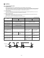
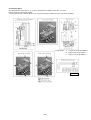
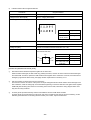
[2] Brazing
No changes from the conventional method, but special care is required so that foreign matter (ie. oxide scale, water, dirt,
etc.) does not enter the refrigerant circuit.
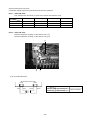
Example : Inner state of brazed section
When non-oxide brazing was not used
When non-oxide brazing was used
Items to be strictly observed :
1. Do not conduct refrigerant piping work outdoors on a rainy day.
2. Apply non-oxide brazing.
3. Use a brazing material (Bcup-3) which requires no flux when brazing between copper pipes or between a copper pipe
and copper coupling.
4. If installed refrigerant pipes are not immediately connected to the equipment, then braze and seal both ends of them.
Reasons :
1. A flux generally contains chlorine. A residual flux in the refrigerant circuit may generate sludge.
Note :
• Commercially available antioxidants may have adverse effects on the equipment due to its residue, etc. When
applying non-oxide brazing, use oxygen free nitrogen (OFN).
–4–
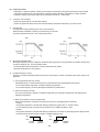
[3] Airtightness Test
Items to be strictly observed :
1. Pressurize the equipment with nitrogen up to the design pressure and then judge the equipment’s airtightness, taking
temperature variations into account.
Reasons :
1. Use of oxygen as the pressurized gas may cause an explosion.
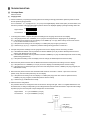
[4]
Vacuuming
1. Standard degree of vacuum for the vacuum pump
Use a pump which reaches 65 Pa (0.0094 psi) or below after 5 minutes of operation.
In addition, be sure to use a vacuum pump that has been properly maintained and oiled using the specified oil. If the
vacuum pump is not properly maintained, the degree of vacuum may be too low.
2. Required accuracy of the vacuum gauge
Use a vacuum gauge that can measure up to 650 Pa (0.094 psi). Do not use a general gauge manifold since it cannot
measure a vacuum of 650 Pa (0.094 psi).
3. Evacuating time
• Evacuate the equipment for 1 hour after 650 Pa (0.094 psi) has been reached.
• After envacuating, leave the equipment for 1 hour and make sure that the vacuum is not lost.
4. Operating procedure when the vacuum pump is stopped
In order to prevent a backflow of the vacuum pump oil, open the relief valve on the vacuum pump side or loosen the
charge hose to drawn in air before stopping operation.
The same operating procedure should be used when using a vacuum pump with a check valve.
–5–
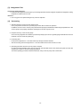
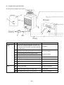
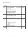
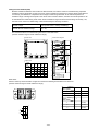
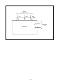
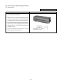
2 COMPONENT OF EQUIPMENT
[1] Appearance of Components
Propeller fan
Fan motor
Heat exchanger(rear)
Heat exchanger(front)
Control box
Compressor
4-way valve
CV block
SV block
Fusible plug Accumulator
Compressor
–6–
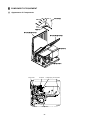
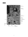
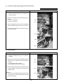
Controller Box
INV board
MAIN board
Choke coil (L2)
Terminal block TB7 Transmission (Centralized control)
Terminal block TB1 Power Source
Terminal block TB3 Transmission
Intelligent Power Module (IPM)
G/A board
Capacitor (C1) (Smoothing capacitor)
Magnetic contactor (52C)
Diode stack (DS)
Power board
–7–
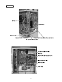
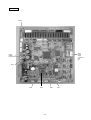
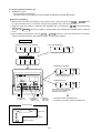
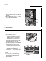
MAIN board
CNS1
CNS2
CN40
CN41
CNVCC3
Power Source
for control
1-2 30V
1-3 30V
4-6 12V
5-6 5V
CNVCC5
Power Source for control(5V)
CN51
Indication distance
3-4 Compressor ON/OFF
3-5 Trouble
CNRS3
Serial transmission to
INV board
CN3D
CN3S
LD1
Service LED
CN20
Power Input
7 L1
5 L2
3 L3
1G
CNAC3
SW4
Power Output
5 L1
3 L3
1G
SW3
SWU2 SWU1
–8–
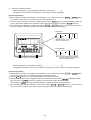
SW2
SW1
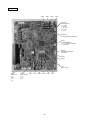
INV board
CNDC2
1-3 DC-325V
CN15V2
Power Output
for IPM control
CNVCC4
Power Output (5V)
CNL2
Choke coil
CNVCC2
Power Output
1-2 30V, 1-3 30V
4-6 12V, 5-6 5V
SW1
CNDR2
Output to
G/A board
CNCT
CNTH
CNAC2
Power Input
5 L1
3 L3
1G
CNFAN
Control for MF1
CN52C
Control for 52C
–9–
CNRS2
Serial transmission
to MAIN board
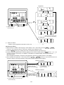
G/A board
CNE
CNDC1
CN15V1
CNIPM1
CNDR1
Power board
–10–
BC controller
CNTR
CN12
Power
supply
1 EARTH
3N
5L
CN02
M-NET
transmission
CN03
SW4
SW5
SW2
–11–
SW1
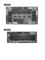
RELAY 10 board
RELAY 4 board
–12–
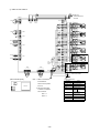
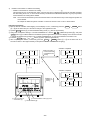
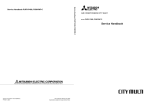
[2] Refrigerant Circuit Diagram and Thermal Sensor
:
Solenoid valve
:
Orifice
:
Capillary
:
Check valve
: Thermal sensor
SP
ACC
:
Strainer
:
Service port
: Accumulator
:
HPSV
High pressure
Solenoid Valves
safety valve
Block
Distributor
CJ1
63HS
SV3
O/S
SV4
SV6
SV5
CJ2
HEXb
CP1
ST6
TH7
SV1
CV1
SV2
HPSV
TH1
CV7
HEXf3
TH6
63LS
ACC
63H
HEXf2
SA
Comp
MA
HEXf1
SLEV
CV2
CV8 CV9
CV10
CV3
ST1
CV4
BV1
CV5
CV6
TH5
BV2
Check Valves Block
SVC
SVA
SVB
Gas/liquid separator
TH23
TH12
TH21
Indoor
units
TH11
TH22
63HS1
LEV
LEV1
63HS3
TH15
LEV3
TH16
BC controller
CMB-104NU-F
–13–
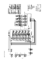
[3] Electrical Wiring Diagram
1
MC
U
Noise filter board
(POWER-BOARD)
DS(Diode stack)
TB1
L1
Power source
3~208-230V 60Hz
Connect to
indoor and
remote
controller
~
L2
~
L3
~
Red
+
IPM
R1
FN1
FN3
FN6
Red
DCL
52C
Blue
Ð
FN2
FN4
White
Red
CN20
(7P)
Blue
Ground
Green
GR
G
L3
L2
L1
1
3
5
7
F2
6.3A
DSA
A
B
1 2
CNS1
(2P)
F1
6.3A
TB7
A
1
B
C1
2 3
CNS2
(3P)
1 2 3 4
CN40
(4P)
1 2 3 4
ZNR1~4
CN41
(4P)
3 CN32
2 (3P)
1
21
S4
SV
2
SV
4
SV
5
SV
6
MF
63H
6 CN34
5 (6P)
4 Red
3
2
1
1 CN36
2 (9P)
3
4
5
6
7
8
9
X02
X03
Control circuit board
(MAIN-BOARD)
X04
X05
CNLV1
(5P)
Blue
TB7
GR
DCL
DCCT
R1
G
G
L3
L3
L1
L1
1
2
3
4
5
V
Gate amp board
(G/A-BOARD)
Blue
W
1 2
CNE
(2P)
CNDR1
CN15V1
(9P)
(14P)
1 2 3 4 56 7 8 9 1 2 3 4 56 7 8 9 1011 121314
1 2 3 4 56 7 8 9 1 2 3 4 56 7 8 9 1011 121314
CNDR2
CN15V2
(9P)
(14P)
X01
F01
2A
Green
CNTH
(2P)
1 2
SLEV
W
White
Power circuit board
(INV-BOARD)
1
2 CNVCC2
3 (6P)
4
5
6
Yellow
1 CNVCC4
2 (2P)
1 CNAC2
2 (5P)
3
4
5
U
V
THHS
CNL2
(2P)
1 2
L2
Red
CN30V
(2P)
1 2
R2
Red
CNFAN
(3P)
1 2 3
MF
1
12V
X08
3
2
1
Red
CN03
(3P)
1 2 3
Detection
Circuit
DC reactor
(Power factor improvement)
Current Sensor
Resistor rush current protect
1
2 CNRS2
3 (7P)
4
5
6
7
1
2
3
4
5
X07
Name
Terminal block power source
Terminal block transmission
Terminal block transmission
centralized control
Ground terminal
1 2 3 4 123
CNCT CNDC2
(3P)
1(4P)
Yellow
2 CN52C
3 (3P)
5 Trouble
4 Compressor ON/OFF
3
2 CN51
1 (5P)
5
4 CNFAN1
3 (5P)
2 Red
1
3 CN38
2 (3P)
1 Green
Yellow
CNDC1 1 2 3
(3P)
1
2
3
4
5
6
7
X06
TH6
Symbol
TB1
TB3
CNAC3
(5P)
R2
C1
Symbol
52C
IPM
MC
MF
MF1
CH1
21S4
CN02
(8P)
1 2 3 4 5 6 7 8
TH5
TH7
CN01
(2P)
1 2
TH1
CNL
(3P)
1 2 3
3 2 1
3 2 1
63LS
Name
Resistor power regulation
Capacitor Smoothing
Magnetic contactor
(Inverter main circuit)
Intelligent power module
Motor Compressor
Motor Fan Heat exchanger
Motor Fan Radiator panel
Crankcase heater (Compressor)
4-way valve
3
2
1
CNH
(3P)
1 2 3
Black
White
Red
SV
1
SV
3
6 CN33
5 (6P)
4
3
2
1
CNRS3
(7P)
1
CNVCC3 2
3
(6P)
4
5
6
Yellow
CNVCC5 12
(2P)
Black
White
Red
CH1
X01
52
C
F01
3.15A
N
Blue
DCCT
Shield
P
+
1 2 3 4
TB3
Red
Symbol
SV3~6
TH7
–14–
CN3S
(3P)
Red
Demand
Night mode
Snow sensor
63HS
SV1, SV2
63H
TH1
TH5
TH6
CN3D
(3P)
Name
Solenoid valve
(Discharge-suction bypass)
Solenoid valve
(Heat exchanger capacity control)
High pressure switch
Thermistor discharge pipe temp.detect
pipe temp.detect
OA temp.detect
liquid outlet temp.
detect at Sub-cool coil
Symbol
THHS
63HS
63LS
SLEV
L2
Name
Thermistor Rediator panel
temp.detect
High pressure sensor
Low pressure sensor
Electronic expansion valve
(Oil return)
Choke coil(Transmission)
Ground
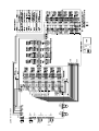
2 CMB-104·105·106NU-F
TR
TB02
Shield wire
Transmission line
DC 30V
M2
M1
CONT.B
3
2
PS1
1
1
1
2
3
3
2
CN03
1
2
CNTR
1
CN02
X2
CNP1
X1
X30
3
2
PS3
1
1
2 2
X4
CNP3
3
X3
X31
3
3 3
5
4 4
1
5 5
3
6 6
5
7 7
3
4
4
1
1
2
2
3
3 T2
SV2A
4
4
SV2C
1
1
2
2
3
3 T3
SV3A
4
4
SV3C
1
1
2
2
3
3 T4
SV4A
4
4
SV4C
1
1 CMB-105 106NU-F ONLY
2
2
3
3 T5
SV5A
4
4
SV5C
1
1 CMB-106NU-F ONLY
2
2
3
3 T6
SV6A
4
4
SV6C
SV1B
T1
SV1A
SV1C
1
X6
2
X5
5
X32
CN10
1
8 8
3
9 9
5
10 10
SV3B
7
X8
6
X7
7
8
X33
CN29
1
11 11
3
12 12
5
13 13
SV4B
7
1
2
3
SV2B
7
CN28
4
TH16
2
3
CN27
CN13
3
TH15
1
2
7
2
2
TH12
1
1 1
CN26
1
1
TH11
3
X10
CN11
X9
4
X34
F01
X12
6.3A F
1 2 3 4 5 6
CN05
1 2 3 4 5 6
1
14 14
3
15 15
5
16 16
7
250VAC
CN07
CN30
1
CN12
3
CN31
1
1 1
X11
3
X35
5
2 2
3 3
5
7
SV6B
4 4
TB01
LEV3
SV5B
L1
L2
LEV1
Power source
~208V-230V 60Hz
G
(Box internal layout)
Note : 1.TB02 is transmission
(Symbol explanation)
TR
Never connect power
CONT.B
TB01
TB02
Name
Symbol
terminal block.
line to it.
2.The initial set values
TR
Transformer
TH11,12,15,16
Thermistor sensor
LEV1,3
Expansion valve
PS1,3
Pressure sensor
of switch on CONT.B
CONT.B
are as follows.
TB01
SW1 : 0
TB02
SW2 : 0
–15–
Circuit
BC controller
board
Terminal block
(for power source)
Terminal block
(for Transmission)
SV1~6A,B,C
Solenoid valve
T1~6
Terminal
F01
Fuse AC250V 6.3A T
TH16
TH15
TH12
TH11
PS3
PS1
3
2
1
3
2
1
LEV1
LEV3
CN05
CN02
2 1
1 2 3 4 5 6
CN03
3 2 1
1 2 3 4 5 6
CN07
1
2
CN11
3
4
1
2
3
4
CN10
5
6
7
8
1
2 CN13
1
2 CNP3
3
CNP1
1
2
3
CONT.B
7 6 5 4 3 2 1
1
CN12
3 5
F01
250VAC
6.3A F
CN50
CN38
1 3
1
3
X12
X11
X35
X10
X9
X34
7
1
3
5
CN31
7
1
3
5
CN30
7
X8 CN291
X7
3
X33
5
7
X6 CN281
X5
3
X32
5
7
7
X4 CN271
X3
3
X31
5
X2 CN261
X1
3
X30
5
CNTR
TB01
G
L1
L2
11
22
3 3
1414
1515
16 16
1111
1212
13 13
88
99
10 10
55
66
7 7
11
22
33
4 4
1
2
3T6
4
1
2
3T5
4
1
2
3T4
4
1
2
3T3
4
1
2
3T2
4
1
2
3T1
4
Power source
~208V-230V 60Hz
2
3
4
1
2
3
4
1
2
3
4
1
2
3
4
1
2
3
4
1
1
2
3
4
SV6B
SV6A
SV6C
SV5B
SV5A
SV5C
SV4B
SV4A
SV4C
SV3B
SV3A
SV3C
SV2B
SV2A
SV2C
SV1B
SV1A
SV1C
Shield wire
Transmission line
DC 30V
3
CN39
1
16
16
3
3
T10
2
2
1
3
5 7
15 14 13
15 14 13
4
4
1
1
CMB-1010NU-F ONLY
CN35
M2
M1
4
4
3
3
T9
2
2
1
3
5 7
12 11 10
12 11 10
CN34
SV10C
SV10A
SV10B
X20
X19
X39
SV9C
SV9A
SV9B
1
1
8
8
3
1
3
3
7
7
T8
9
9
4
4
7 6 5 4 3 2 1
X18
X17
X38
TB02
CN33
TR
5 7
2
2
1
CN52
1
3
1
3
3
T7
5 4
5 4
4
4
6
6
CN32
SV8C
SV8A
SV8B
X16
X15
X37
5 7
2 1
2
SV7C
SV7A
SV7B
X14
X13
X36
3 CMB-108·1010NU-F
1
REL.B
TB02
TB01
TR
(Box internal layout)
CONT.B
Note : 1.TB02 is transmission
terminal block.
Never connect power
line to it.
2.The initial set values
of switch on CONT.B
are as follows.
SW1 : 0
SW2 : 0
(Symbol explanation)
Symbol
Name
Transformer
TR
TH11,12,15,16 Thermistor sensor
Expansion valve
LEV1,3
Pressure sensor
PS1,3
REL.B
Circuit Relay
board BC controller
CONT.B
Terminal block
TB01
(for power source)
Terminal block
TB02
(for Transmission)
SV1~10A,B,C Solenoid valve
Terminal
T1~10
Fuse AC250V 6.3A T
F01
REL.B
–16–
TH16
TH15
TH12
TH11
PS3
PS1
3
2
1
3
2
1
LEV1
LEV3
CN05
2 1
CN02
1 2 3 4 5 6
CN03
3 2 1
1 2 3 4 5 6
CN07
1
2
CN11
3
4
1
2
3
4
CN10
5
6
7
8
1
CN13
2
1
2 CNP3
3
CNP1
1
2 3 2 1
3 CNVCC1
CONT.B
CN12 1 3 5
F01
250VAC
6.3A F
CNOUT3
1
2
3
4
1
2
3
4
5
6
7
8
CNOUT1
CN38
1 3
1
3
7
1
3
5
CN30
7
X12 CN311
X11
3
X35
5
X10
X9
X34
7
X8 CN291
X7
3
X33
5
7
X6 CN281
X5
3
X32
5
7
X4 CN271
X3
3
X31
5
7
X2 CN261
X1
3
X30
5
CNTR
G
L1
L2
TB01
11
22
3 3
1414
1515
16 16
1111
1212
13 13
8 8
9 9
10 10
55
66
7 7
11
22
33
4 4
1
1
2
3T6
4
1
2
3T5
4
1
2
3T4
4
1
2
3T3
4
1
2
3T2
4
Power source
~208V-230V 60Hz
2
3
4
1
2
3
4
1
2
3
4
1
2
3
4
1
2
3
4
1
2
3 T1
4
SV6B
SV6A
SV6C
SV5B
SV5A
SV5C
SV4B
SV4A
SV4C
SV3B
SV3A
SV3C
SV2B
SV2A
SV2C
SV1B
SV1A
SV1C
Shield wire
Transmission line
DC 30V
1
2
3
4
M2
M1
TB02
16
16
4 3 2
T10
4 3 2 1
1
3
5 7
15 14 13
15 14 13
CN35
TR
1
2
3CNOUT4
4
1
2
3
4
5 CNOUT2
6
7
8
1
3
1
5 7
1
3
9 8 7
9 8 7
12 11 10
12 11 10
5 7
4 3 2
1
4 3 2
T8
4 3 2 1
T9
4 3 2 1
1
3
6 5 4
6 5 4
TB02
TB01
TR
5 7
4 3 2
T7
4 3 2 1
1
CONT.B
(Box internal layout)
1
CN32
4 CMB-1013·1016NU-F
CN34
SV10C
SV10A
SV10B
X20
X19
X39
SV9C
SV9A
SV9B
X18
X17
X38
SV7C
SV7A
SV7B
X14
X13
X36
SV8C
SV8A
SV8B
CN33
X16
X15
X37
REL.B
–17–
3 2 1
CN39 CNVCC2
1 3
7
7
1
3
5
7
1
3
5
7
1
3
5
7
1
3
5
7
1
3
5
1
3
5
REL.B
11
22
33
4 4
1313
1414
1515
16 16
1010
1111
12 12
77
88
9 9
44
55
6 6
11
22
3 3
2
3
4
2
3
4
1
2
3
4
1
1
2
3
4
2
3
4
1
1
2
3
4
1
SV12B
SV12A
SV12C
SV13B
SV13A
SV13C
1
2
3T12
4
1
2
3T13
4
SV15B
SV15A
SV15C
SV16B
SV16A
SV16C
1
2
3T15
4
1
2
3T16
4
1 CMB-1016NU-F ONLY
2
SV14B
3T14
SV14A
4
SV14C
SV11B
SV11A
SV11C
1
2
3T11
4
Name
Transformer
Thermistor sensor
Expansion valve
Pressure sensor
Circuit Relay
board BC controller
Terminal block
(for power source)
Terminal block
(for Transmission)
Solenoid valve
Terminal
Fuse AC250V 6.3A T
Note : 1. TB02 is transmission terminal block.
Never connect power line to it.
2. The initial set values of switch on CONT.B
are as follows.
SW 1 : 0
SW 2 : 0
CN40
X41
X40
X42
CN41
X44
X43
X45
CN42
X47
X46
X48
CN43
X50
X49
X51
CN44
X53
X52
X54
CN45
X56
X55
X57
TB02
SV1~16A,B,C
T1~16
F01
Symbol
TR
TH11,12,15,16
LEV1,3
PS1,3
REL.B
CONT.B
TB01
(Symbol explanation)
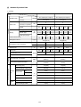
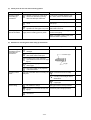
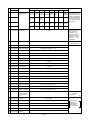
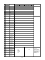
[4] Standard Operation Data
1 Cooling
Outdoor unit
PURY-80TMU
PURY-100TMU
26.7˚C(80˚F)/19.4˚C(67˚F)
26.7˚C(80˚F)/19.4˚C(67˚F)
35˚C(95˚F)
35˚C(95˚F)
4
4
4
4
Items
Ambient temp.
Indoor
DB/WB
Outdoor
Quantity
Q’ty
Indoor unit
Quantity in operation
–
Condition
Model
24
24
Main pipe
Piping
Branch pipe
48
16
24
10
5(16.4)
5(16.4) 5(16.4) 5(16.4) 5(16.4) 5(16.4) 5(16.4) 5(16.4) 5(16.4)
25(82)
–
Refrigerant volume
10
5(16.4)
m
(Ft)
Total piping length
Indoor unit fan notch
20
Hi
Hi
kg(oz)
25(82)
Hi
Hi
Hi
Hi
10 kg(67 oz)
Hi
Hi
12 kg(86 oz)
V
208
230
208
230
V/Hz
134/76
134/76
171/98
171/98
A
27.4
24.8
35.2
31.8
Compressor volts / Frequency
LEV opening
High pressure/Low pressure
Sectional temperature
Indoor unit
Pressure
Outdoor unit
330
BC controller (1, 3)
Pulse
300
140
410
330
460
2000
235
2.03/0.49
(294/71)
1.90/0.39
(276/57)
1.92/1.92
(279/279)
1.79/1.79
(25/25)
Discharge (TH1)
107(225)
110(230)
Heat exchanger outlet (TH5)
50(122)
47(117)
7(45)
7(45)
10(50)
10(50)
12(54)
12(54)
Shell bottom (Comp)
75(167)
70(158)
LEV inlet
26(79)
30(86)
Heat exchanger outlet
15(59)
15(59)
BC controller liquid/Intermediate
Inlet
Accumulator
Outlet
Suction (Comp)
˚C
(˚F)
–18–
300
150
235
MPa
(psi)
Indoor
unit
430
2000
Oil return
Outdoor
unit
460
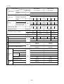
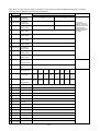
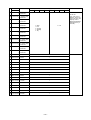
2 Heating
Outdoor unit
PURY-80TMU
PURY-100TMU
21.1˚C(70˚F)
21.1˚C(70˚F)
8.3˚C(47˚F)/6.1˚C(43˚F)
8.3˚C(47˚F)/6.1˚C(43˚F)
4
4
4
4
Items
Indoor
Ambient temp.
DB/WB
Outdoor
Quantity
Q’ty
Indoor unit
Quantity in operation
Condition
Model
–
24
24
Main pipe
Piping
Branch pipe
LEV opening
Indoor unit
Pressure
Outdoor unit total current
Hi
Hi
High pressure/Low pressure
Hi
Hi
Hi
Hi
12 kg(86 oz)
230
V/Hz
149/85
149/85
174/100
174/100
A
27.5
24.9
35.6
32.2
950
750
60
700
400
750
600
950
60
235
1.81/0.35
(263/51)
1.76/0.36
(256/53)
1.72/1.37
(249/199)
1.67/1.37
(242/199)
100(212)
95(203)
–2(28)
–1(30)
–1(30)
–1(30)
–4(25)
–2(28)
–1(30)
–1(30)
Shell bottom (Comp)
45(113)
40(104)
LEV inlet
38(100)
40(104)
Heat exchanger outlet
80(176)
85(185)
MPa
(psi)
Inlet
Accumulator
Suction (Comp)
˚C
(˚F)
–19–
400
800
150
Outlet
Hi
208
Heat exchanger outlet (TH5)
Sectional temperature
Hi
230
Discharge (TH1)
Indoor
unit
25(82)
208
Pulse
BC controller liquid/Intermediate
10
V
Oil return
Outdoor
unit
24
5(16.4)
10 kg(67 oz)
600
BC controller (1, 3)
16
5(16.4) 5(16.4) 5(16.4) 5(16.4) 5(16.4) 5(16.4) 5(16.4) 5(16.4)
kg(oz)
Compressor volts / Frequency
48
25(82)
–
Refrigerant volume
10
5(16.4)
m
(Ft)
Total piping length
Indoor unit fan notch
20
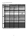
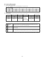
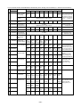
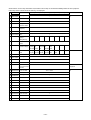
[5] Function of Dip SW and Rotary SW
(1) Outdoor unit
Switch
Function
SWU
SW1
1~2 Unit address setting
1~8 For self diagnosis/
operation monitoring
9~10
–
1 Centralized control switch
SW2
SW3
2
Deletion of connection
information.
3
Deletion of error history.
4
5
6
7
–
–
Disregard ambient air
sensor errors, liquid
overflow errors.
Forced defrosting
8
Defrost prohibited timer
9
10
1
–
–
SW3-2 Function valid/
invalid
Indoor unit test operation
2
3
4
5
6
7
SW4
8
9
10
1
2
3
4
5
6
7
8
9
10
Function according to switch operation
When off
When on
Set on 51~100 with the dial switch.
LED monitering display
–
Centralized control not
connected.
Storing of refrigeration
system connection
information.
–
–
Centralized control
connected.
Deletion of refrigeration
system connection
information.
Deletion
Errors valid.
–
–
Disregard errors.
Ordinary control
Start forced defrosting.
–
–
90 min.
50 min.
–
–
SW3-2 Function invalid
–
–
SW3-2 Function valid
Stop all indoor units.
All indoor units test
operation ON.
–3°C
(27˚F)
15°C
(59˚F)
–
Valid
Defrosting start temperature of TH7.
Defrosting end temperature of TH5.
–
Pump down operation
–6°C
(21˚F)
8°C
(46˚F)
–
Invalid
Target Td (High pressure)
at Heating
–
–
Models
–
–
–
–
LED Display
–
–
–
–
–
49˚C
(120˚F)
–
–
Model 80
–
–
–
–
“˚F” “psig” Display
–
–
–
–
–
53˚C
(127˚F)
–
–
Model 100
–
–
–
–
“˚C” “kgf/amG” Display
–
–
–
–
–
Switch set timing
When off
When on
Before power is turned on.
During normal operation when power
is on.
Should be set on OFF.
Before power is turned on.
Before power is turned on.
During normal operation when power
is on.
–
–
During normal operation when power
is on.
During normal
operation when
power is on.
10 minutes or
more after
compressor
starts.
During normal operation when power
is on. (Except during defrosting)
–
–
During normal operation when power
is on.
When SW3-1 is ON after power is
turned on.
During normal operation when power
is on.
During normal operation when power
is on. (Except during defrosting)
–
During compressor stop when power
is on.
During normal operation when power
is on.
–
–
When switching on the power.
–
–
–
–
When switching on the power
–
–
–
–
–
Note:
• SWU1~2=00 when shipped from the factory. Other factory settings are indicated by shaded portions.
• If the address is set from 01 to 50, it automatically becomes 100.
–20–
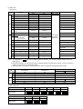
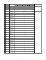
(2) Indoor unit
DIP SW1, 3
Switch
SW1
Switch set timing
OFF
ON
1
Room temp. sensor position
Indoor unit inlet
Built in remote controller
2
3
Clogged filter detect.
None
Provided
Filter duration
100h
2500h
4
OA intake
Ineffective
Effective
5
Remote display select.
Fan output display Thermo. ON signal display
6
Humidifier control
At stationary heating
Always at heat.
7
Heating thermo. OFF airflow
Very low speed
Low speed
8
Heating thermo. OFF airflow
SW1-7 setting
Set airflow
9
Power failure automatic
return
Ineffective
Effective
–
–
Heat pump
Cool.only
None
Provided
10
1
SW3
Operation by SW
OFF
ON
SW name
–
Model selection
Cooling capacity saving
for PKFY-NAMU,
effective/ineffective
Always ineffective for PKFY-NAMU
2
Louver
3
Vane
None
Provided
4
Vane swing function
None
Provided
5
Vane horizontal angle
1st setting
2nd setting
6
Vane angle set for cooling
Down blow B, C
Horizontal
–
–
Effective
Ineffective
7
8
–
Heating 4deg (7.2 deg) up
Note : °C scale (°F scale)
9
–
–
–
10
–
–
–
Remarks
At unit stopping
(at remote
controller OFF)
Not provided for PKFY-NAMU
Provided for PLFY-NGMU (ON) setting
Always down blow B,C for
PKFY-NAMU
Note 1: The shaded part
indicates the setting at factory shipment. (For the SW not being shaded, refer to the
table below.)
2: The DipSW setting is only effective during unit stopping (remote controller OFF) for SW1, 2, 3 and 4 commonly
and the power source is not required to reset.)
3: When both SW1-7 and SW1-8 are being set to ON, the fan stops at the heating thermostat of OFF.
Model
PKFY
PLFY-NAMU-A
PDFY-NMU-A
3
ON
ON
OFF
6
ON
ON
OFF
7
OFF
OFF
OFF
3
ON
OFF
4
ON
OFF
6
OFF
OFF
OFF
8
OFF
OFF
OFF
NAMU-A
Switch
SW1
SW3
NGMU-A
ON
OFF
ON
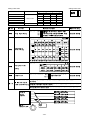
Setting of DIP SW2
Model
08
10
12
16
20
24
Capacity (model name) code
4
5
6
8
10
13
SW2 setting
Model
32
Capacity (model name) code
SW2 setting
ON
OFF
ON
OFF
16
ON
OFF
ON
OFF
ON
OFF
ON
OFF
40
48
20
25
ON
OFF
–21–
ON
OFF
ON
OFF
Setting of DIP SW4
Model
Setting of DIP SW5
SW4
Circuit board used
1
2
3
4
PDFY-10 ~ 32
ON
OFF
ON
OFF
PLFY-12 ~ 24
OFF
OFF
OFF
ON
ON
OFF
OFF
ON
PKFY-P-8
OFF
OFF
ON
ON
PKFY-P-12
–
–
–
–
OFF
OFF
ON
–
PLFY-32 ~ 48
Phase control
Relay selection
PDFY-40, 48
Switch
Operation by switch
Function
(PLFY)
Ceiling height setting
Switch set timing
* SWA sets the type of unit, I.E.2, 3 or 4 way
2-way
SWA
208V
230V
blowing.
3-way
The ceiling height is changed by SWB setting.
4-way
As shown for SWB explanation below.
(PDFY-10 ~ 32NMU-A)
10
Pa (in.WG)
16
24
32
208V 230V 208V 230V 208V 230V
80
3
100
50
60
50
208V
230V
Ð
Ð
60
(0.320) (0.401) (0.200) (0.240) (0.200) (0.240)
SWC
SWA
External static
100
Option
pressure setting
50
2
60
80
100
80
Standard
100
(0.200) (0.240) (0.320) (0.401) (0.320) (0.401)
SWC
Standard
30
40
30
40
30
50
Standard
60
30
Option
(0.120) (0.160) (0.120) (0.160) (0.120) (0.160)
Always after powering
(0.200) (0.240)
SWC
40
115
(0.401) (0.461)
Option
1
Always after powering
40
(0.120) (0.160)
* For other models, change the setting of static pressure by replacing the connector.
(PLFY)
m (ft)
SWB
SWB
1
2
3
2-way
3.5 (11.48)
3.8 (12.46)
3.8 (12.46)
3-way
3.0 (9.84)
3.3 (10.82)
3.5 (11.48)
4-way
2.7 (8.86)
3.0 (9.84)
3.5 (11.48)
SWA
Setting of air outlet
opening
(PLFY, PKFY-NGMU)
SWC
* Set to the option to install the
Option
Airflow control
Always after powering
high efficiency filter
Always after powering
Standard
Set to the branch number of the B/C controller to which the indoor unit is
connected.
SW1-4
B/C Controller branch
If the indoor unit (s) capacity code is greater then 32 a joint pipe is required, set the
number address setting dip switch to the lower branch number.
The port address of the next unit connected to the B/C controller should take in to
account the use of the joint pipe.
B/C
Controller
Branch
Numbers
1
SW 1-4 01 Indoor Unit
Capacity code above 32
2
SW 1-4 03 Indoor Unit
3
Capacity code below 32
4
SW 1-4 04 Indoor Unit
Capacity code above 32
5
SW 1-4 06 Indoor Unit
6
Appearance
SW1-4
Capacity code below 32
0
Joint
Pipe
Factory set to "0"
–22–
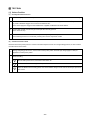
3 TEST RUN
[1] Before Test Run
(1) Check points before test run
1
Neither refrigerant leak nor loose power source/ transmission lines should be found, if found correct immediately.
2
Confirm that the resistance between the power source terminal block and the ground exceeds 2MΩ by measuring it with a DC500V megger. Do not run if it is lower than 2MΩ.
Note : Never apply the megger to the MAIN board. If applied, the MAIN board will be broken.
3
Confirm that the Ball valve at both gas and liquid sides are fully opened.
Note : Close the cap.
4
Be sure that the crankcase heater has been powered by turning the main power source on at least 12 hours
before starting the test run. The shorter powering time causes compressor trouble.
(2) Caution at inverter check
Because the inverter power portion in outdoor unit electrical part box have a lot of high voltage portion, be sure to follow
the instructions shown below.
1
During energizing power source, never touch inverter power portion because high voltage (approx. 580V) is
applied to inverter power portion.
When checking,
1
Shut off main power source, and check it with tester, etc.
2
Allow 10 minutes after shutting off main power source.
3
Open the MAIN board mounting panel, and check whether voltage of both ends of electrolytic capacitor is
20V or less.
2
–23–
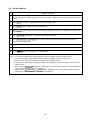
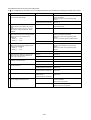
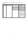
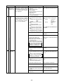
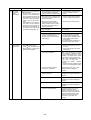
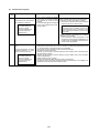
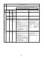
(3) Check points for test run when mounting options
Built-in optional parts
Mounting of drain
water lifting-up
mechanism
Check point
Content of test run
1
Release connector of pump circuit,
check error detection by pouring
water into drain pan water inlet.
Result
Local remote controller displays code
No. “2503”, and the mechanism stops.
No overflow from drain pan.
Mounting of permeable film humidifier
Drain water comes out by operation of
drain pump.
2
After that, connect connector of
circuit.
3
Check pump operations and drainSound of pump operations is heard, and
age status in cooling (test run) mode. drain water comes out.
Check humidifier operations and water
supply status in heating (test run) mode.
No water leak from connecting portions
of each water piping.
Water is supplied to water supply tank,
and float switch is operating.
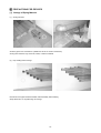
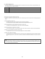
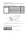
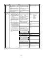
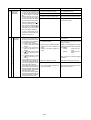
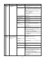
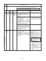
(4) Attention for mounting drain water lifting-up mechanism
Work
Disassembling and
assembling of drain
water lifting-up
mechanism
Mounting of float
switch
Electric wiring
Check point
Content of test run
1
Lead wire from control box not
damaged.
2
Rubber cap properly inserted in to
drain water outlet of drain pan?
3
Insulation pipe of gas and liquid
pipes dealt with as shown in the right
figure?
4
Drain pan and piping cover mounted
without gap?
5
Drain pan hooked on cut projection
of the mechanism?
Float switch installed without contacting the
drain pan?
Insulation pipe
No gap
1
Float switch moves smoothly.
2
Float switch is mounted on
mounting board straight without
deformation.
3
Float switch does not contact the
copper pipe.
1
No mistakes in wiring?
Wiring procedure is exactly followed.
2
Connectors connected securely and
tightly?
Connector portion is tightly hooked.
3
No tension on lead wire when sliding
control box?
–24–
Result
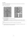
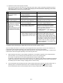
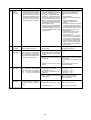
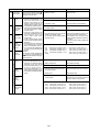
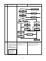
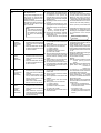
(5) Check points for system structure
Check points from installation work to test run.
Classification
Installation and
piping
Power source
wiring
Portion
Trouble
Check item
1
Instruction for selecting combination of outdoor unit,
and indoor unit followed? (Maximum number of indoor
Not operate.
units which can be connected, connecting model name,
and total capacity.)
2
Follow limitation of refrigerant piping length? For example,
70m (229ft) or less (total length : 220m (721ft)) at the farthest.
Not cool (at cooling).
3
Connecting piping size of branch piping correct?
4
Refrigerant piping diameter correct?
5
Refrigerant leak generated at connection?
Not cool, not heat, error stop.
6
Insulation work for piping properly done?
Condensation drip in piping.
7
Specified amount of refrigerant replenished?
Not cool, not heat, error stop.
8
Pitch and insulation work for drain piping properly done? Water leak, condensation drip in drain piping.
Not heat (at heating).
1
Specified switch capacity and wiring diameter of main
power source used?
Error stop, not operate.
2
Proper grounding work done on outdoor unit?
Electric shock.
3
The phases of the L line (L1, L2, L3) correct?
Error stop, not operate.
–25–
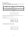
DRY COOL
AUTO FAN
HEAT
CENTRALLY CONTROLLED
DAILY TIMER AUTO AUTO
CLOCK ON OFF
CHECK SET TEMP. REMAINDER
HEAT
EROR CODE
2
3
MODE
TIMER
CLOCK ON OFF
FAN SPEED
CENTRALLY CONTROLLED
DAILY TIMER AUTO AUTO
CLOCK ON OFF
CHECK SET TEMP. REMAINDER
EROR CODE
MODE
TIMER
CLOCK ON OFF
VENTILATION CHECK TEST
ON/OFF
FAN SPEED
LOUVER
TIMER SET
PAR-F27MEA-US
AIR DIRECTION FILTER
VENTILATION CHECK TEST
TIMER SET
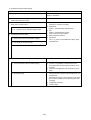
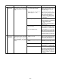
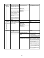
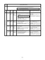
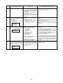
Classification
Portion
Transmission
line
1
Limitation of transmission line length followed? For example,
Erroneous operation, error stop.
200m (656ft) or less (total length : 500m (1640ft)) at the farthest.
2
1.25mm2 (AWG16) or more transmission line used?
Erroneous operation, error stop.
(Remote controller 10m (32ft) or less 1.25mm2 (AWG16))
3
2-core cable used for transmission line?
4
Transmission line apart from power source line by 5cm (2in) or more? Erroneous operation, error stop.
5
One refrigerant system per transmission line?
6
The short circuit connector is changed form CN41 to
Not operate.
CN40 on the MAIN board when the system is centralized
control? (Just one outdoor unit. Not all outdoor units.)
7
• No connection trouble in transmission line?
Error stop or not operate.
8
Connection of wrong remote controller line terminals?
• MA Remote controller : TB15
• M-NET Remote controller : TB5
Never finish the initial mode.
1
Address setting properly done? (M-NET Remote
controller, indoor unit and outdoor unit.)
Error stop or not operate.
2
Setting of address No. done when shutting off power
source?
Can not be properly set with power
source turned on.
3
Address numbers not duplicated?
Not operate.
4
Turned on SW3-8 on indoor unit circuit board when
mounting room thermistor sensor?
Set temperature not obtained at
heating operations (Thermostat
stop is difficult)
1
Refrigerant piping ball valve (Liquid pressure pipe, gas
pressure pipe) opened?
Error stop.
2
Turn on power source 12 hours before starting operations? Error stop, compressor trouble.
System set
Before starting
Check item
FILTER
TEST RUN
NOT AVAILABLE
SET TEMP.
AIR DIRECTION FILTER
SENSOR
INSIDE
FAN
SPEED
VENTILATION
STAND BY
DEFROST
ON/OFF
LOUVER
PAR-F27MEA-US
TEST RUN
NOT AVAILABLE
SET TEMP.
1
AUTO FAN
FILTER
VENTILATION
STAND BY
DEFROST
DRY COOL
SENSOR
INSIDE
FAN
SPEED
–26–
Trouble
Error stop in case multiple-core
cable is used.
Not operate.
[2] Test Run Method
Operation procedure
1
Turn on universal power supply at least 12 hours before starting → Displaying “HO” on display panel for about two
minutes
2
Press TEST button twice → Displaying “TEST RUN’’ on display panel
3
Press MODE button → Make sure that air is blowing out
4
Press MODE button to change from cooling to heating operation, and vice versa → Make sure that warm or cold
air is blowing out
5
Press FAN SPEED adjust button → Make sure that air blow is changed
6
Press AIR DIRECTION or LOUVER button to change direction of air blowing make sure that horizontal or
downward blow is adjustable.
7
Make sure that indoor unit fans operate normally
8
Make sure that interlocking devices such as ventilator operate normally if any
9
Press
ON/OFF
button to cancel test run → Stop operation
Note 1:
2:
3:
4:
If check code is displayed on remote controller or remote controller does not operate normally.
Test run automatically stops operating after two hours by activation of timer set to two hours.
During test run, test run remaining time is displayed on time display section.
During test run, temperature of liquid pipe in indoor unit is displayed on remote controller room temperature
display section.
5: When pressing FAN SPEED adjust button, depending on the model, “NOT AVAILABLE” may be displayed on
remote controller. However, it is not a malfunction.
6: When pressing AIR DIRECTION or LOUVER button, depending on the model, “NOT AVAILABLE” may be
displayed on remote controller. However, it is not a malfunction.
–27–
4 GROUPING REGISTRATION OF INDOOR UNITS WITH M-NET REMOTE CONTROLLER
(1) Switch function
• The switch operation to register with the remote controller is shown below:
CENTRALLY CONTROLLED
DAILY TIMER AUTO AUTO
DRY COOL
AUTO FAN
HEAT
CLOCK ON
CHECK SET TEMP. REMAINDER
FILTER
VENTILATION
STAND BY
DEFROST
C Switch to assign
indoor unit address
SENSOR
INSIDE
FAN
SPEED
OFF
EROR CODE
SET TEMP.
F Delete switch
G Registered mode
selector switch
MODE
ON/OFF
CLOCK ON OFF
TIMER
TEST RUN
NOT AVAILABLE
FAN SPEED
LOUVER
E Confirmation switch
AIR DIRECTION FILTER
A Registration/
ordinary mode
selector switch
VENTILATION CHECK TEST
D Registration switch
TIMER SET
PAR-F27MEA-US
B Registration/
ordinary mode
selector switch
H Switch to assign interlocked unit address
Symbol
of switch
Name of actual switch
Registration/ordinary
mode selection switch
A+B
FILTER + LOUVER
Switch to assign indoor
unit address
C
Registration switch
D
Confirmation switch
E
Name
Delete switch
F
Registered mode
selector switch
G
of TEMP
TEST RUN
H
This switch selects the ordinary mode or registered mode (ordinary
mode represents that to operate indoor units).
* To select the registered mode, press the FILTER + LOUVER
button continuously for over 2 seconds under stopping state.
[Note] The registered mode can not be obtained for a while after
powering.
Pressing the FILTER + LOUVER button displays “CENTRALLY
CONTROLLED”.
This button assigns the unit address for “INDOOR UNIT ADDRESS
NO.”
This button is used for group/interlocked registration.
TIMER
This button is used to retrieve/identify the content of group and
interlocked (connection information) registered.
CLOCK →
ON → OFF
This button is used to retrieve/identify the content of group and
interlocked (connection information) registered.
MODE
Switch to assign
interlocked unit address
Description
This button selects the case to register indoor units as group (group
setting mode) or that as interlocked (interlocked setting mode).
for the group setting mode
*The unit address is shown at one spot
while at two spots
for the interlocked setting mode.
of TIMER SET This button assigns the unit address of “OA UNIT ADDRESS NO.”
–28–
(2) Attribute display of unit
• At the group registration and the confirmation/deletion of registration/connection information, the type (attribute) of the
unit is displayed with two English characters.
Display
Type (Attribute) of unit/controller
Indoor unit connectable to remote controller
Outdoor unit
Local remote controller
System controller (MJ)
[Description of registration/deletion/retrieval]
• The items of operation to be performed by the remote controller are given below. Please see the relating paragraph for
detail.
1 Group registration of indoor unit
• The group of the indoor units and operating remote controller is registered.
• It is usually used for the group operation of indoor units with different refrigerant system.
2 Retrieval/identification of group registration information of indoor units
• The address of the registered indoor units in group is retrieved (identified).
3 Retrieval/identification of registration information
• The connection information of any unit (indoor/outdoor units, remote controller or the like) is retrieved (identified).
4 Deletion of group registration information of indoor units
• The registration of the indoor units under group registration is released (deleted).
5 Deletion of the address not existing
• This operation is to be conducted when “6607” error (No ACK error) is displayed on the remote controller caused by
the miss setting at test run, or due to the old memory remained at the alteration/modification of the group composition.
Caution:
When MELANS (MJ-103MTRA for example) is being connected, do not conduct the group/pair registration using
the remote controller. The group/pair registration should be conducted by MELANS. (For detail, refer to the instruction exclusively prepared for MELANS.)
–29–
(3) Group registration of indoor unit
1) Registration method
• Group registration of indoor unit ........................................................................ 1
The indoor unit to be controlled by a remote controller is registered on the remote controller.
[Registration procedure]
1 With the remote controller under stopping or at the display of “HO”, continuously press the FILTER + LOUVER button
(A + B) at the same time for 2 seconds to change to the registration mode. (See the figure below.)
2 Assign the indoor unit address to “INDOOR UNIT ADDRESS NO.” by operating the
(Room temperature
adjustment) (C).
Then press the TEST RUN button (D) to register. In the figure below, the “INDOOR UNIT ADDRESS NO.” is being set
to 001.
3 After completing the registration, press the FILTER + LOUVER button (A + B) at the same time for 2 seconds to
change to the original ordinary mode (with the remote controller under stopping).
Ordinary mode
• Remote controller under stopping
• “HO” under displaying
˚C
˚C
INDOOR UNIT
ADDRESS NO
ERROR CODE
OA UNIT ADDRESS NO
INDOOR UNIT
ADDRESS NO
1
ERROR CODE
OA UNIT ADDRESS NO
1
Group setting mode
˚C
ERROR CODE
OA UNIT ADDRESS NO
• Registration complete
▲
˚C
ERROR CODE
OA UNIT ADDRESS NO
Indicates the type of unit
(Indoor unit in this case)
2+3
• Registration error
ON/OFF
▼
SET TEMP.
MODE
TIMER
CLOCK
ON
OFF
FAN SPEED
AIR DIRECTION
FILTER
˚C
ERROR CODE
OA UNIT ADDRESS NO
LOUVER
PAR-F27MEA-US
VENTILATION CHECK TEST
“88” flickers indicating registration error. (when the indoor unit
registered is not existing)
TIMER SET
2 Assign the
address (C)
1 Change to the 3 Press the
registration
registration
mode (A + B)
switch (D)
System example
Indoor units
Group
Remote controller
–30–
• Confirm the indoor unit address No.
• Confirm the connection of the transmission line.
2)
Method of retrieval/confirmation
• Retrieval/confirmation of group registration information on indoor unit ............... 2
The address of the indoor unit being registered on the remote controller is displayed.
[Operation procedure]
1 With the remote controller under stopping or at the display of “HO”, continuously press the FILTER + LOUVER button
(A + B) at the same time for 2 seconds to change to the registration mode.
2 In order to confirm the indoor unit address already registered, press TIMER button (E). (See figure below.) When the
group of plural sets is registered, the addresses will be displayed in order at each pressing of TIMER button (E).
3 After completing the registration, continuously press the FILTER + LOUVER button (A + B) at the same time for 2
seconds to change to the original ordinary mode (with the remote controller under stopping).
• Registered
▲
1
SET TEMP.
TIMER
CLOCK ON OFF
FAN SPEED
LOUVER
PAR-F27MEA-US
ERROR CODE
OA UNIT ADDRESS NO
Indicates the type of unit
(Indoor unit in this case)
1
• No registration.
AIR DIRECTION FILTER
VENTILATION CHECK TEST
TIMER SET
▼
MODE
ON/OFF
˚C
˚C
ERROR CODE
OA UNIT ADDRESS NO
Note: Only one address will be displayed
when the registration is one even the
switch is how often pressed
1 Press the switch for confirmation (E)
• Retrieval/confirmation of registration information ................................................ 3
The registered information on a certain unit (indoor unit, outdoor unit, remote controller or the like) is displayed.
[Operation procedure]
1 With the remote controller under stopping or at the display of “HO”, continuously press the FILTER + LOUVER button
(A + B) at the same time for 2 seconds to change to the registration mode.
2 Operate MODE button (G) for the interlocked setting mode. (See figure below.)
3 Assign the unit address of which registration information is desired to confirm with the
(TIMER SET) switch
(H). Then press the TIMER button (E) to display it on the remote controller. (See figure below.)
Each pressing of TIMER button (E) changes the display of registered content. (See figure below.)
4 After completing the retrieval/confirmation, continuously press the FILTER + LOUVER button (A + B) at the same
time for 2 seconds to change to the original ordinary mode (with the remote controller under stopping).
–31–
• Registered
ßC
(Alternative
display)
ßC
SET TEMP.
MODE
ON/OFF
CLOCK ON OFF
TIMER
FAN SPEED
LOUVER
AIR DIRECTION FILTER
VENTILATION CHECK TEST
▲
TIMER SET
PAR-F27MEA-US
2
ßC
1+2
(Alternative
display)
1 Set the address
2 Press the switch for
confirmation (E)
ßC
˚C
INDOOR UNIT
ADDRESS NO
ERROR CODE
OA UNIT ADDRESS NO
*
• No registration
Same display will appear when
the unit of “007” is not existing.
▼
˚C
ERROR CODE
OA UNIT ADDRESS NO
3)
Method of deletion
• Deletion of group registration information of indoor unit ...................................... 4
[Operation procedure]
1 With the remote controller under stopping or at the display of “HO”, continuously press the FILTER + LOUVER
button (A + B) at the same time for 2 seconds to change to the registration mode.
2 Press the TIMER button (E) to display the indoor unit address registered. (As same as 2)
3 In order to delete the registered indoor unit being displayed on the remote controller, press the TIMER CLOCK → ON → OFF
(F) button two times continuously. At completion of the deletion, the attribute display section will be shown as “ – – “.
(See figure below.)
Note: Completing the deletion of all indoor units registered on the remote controller returns to “HO” display.
4 After completing the registration, continuously press the FILTER + LOUVER button (A + B) at the same time for 2
seconds to change to the original ordinary mode (with the remote controller under stopping).
• Deletion completed
▲
1
˚C
INDOOR UNIT
ADDRESS NO
In case of group registration with other
indoor unit is existing
MODE
TIMER
CLOCK ON OFF
ON/OFF
FAN SPEED
LOUVER
PAR-F27MEA-US
“– –” indicates the
deletion completed.
AIR DIRECTION FILTER
1
• Deletion completed
VENTILATION CHECK TEST
TIMER SET
In case of no group
registration with other
indoor unit is existing
1 Press the switch for confirmation (F)
twice continuously.
–32–
▼
SET TEMP.
ERROR CODE
OA UNIT ADDRESS NO
˚C
INDOOR UNIT
ADDRESS NO
ERROR CODE
OA UNIT ADDRESS NO
4)
Deletion of information on address not existing
• Deletion of information on address not existing ................................................... 5
This operation is to be conducted when “6607” error (No ACK error) is displayed on the remote controller caused by
the miss setting at test run, or due to the old memory remained at the alteration/modification of group composition,
and the address not existing will be deleted.
Note: The connection information (connection between indoor unit and outdoor unit) on the refrigerant system can
not be deleted.
An example to delete the system controller of “250” from the indoor unit of “007” is shown below.
[Operation procedure]
1 With the remote controller under stopping or at the display of “HO”, continuously press the FILTER + LOUVER button
(A + B) at the same time for 2 seconds to change to the registration mode.
2 Operate MODE button (G) for the interlocked setting mode ( ii ). (See the figure below.)
(TIMER SET) switch (H), and press
3 Assign the unit address existing to “OA UNIT ADDRESS No.” with the
TIMER button (E) to call the address to be deleted. (See the figure below.) As the error display on the remote controller
is usually transmitted from the indoor unit, “OA UNIT ADDRESS No.” is used as the address of the indoor unit.
4 Press the TIMER CLOCK → ON → OFF button (F) twice. (See the figure below.)
5 After completing the deletion, continuously press the FILTER + LOUVER button (A + B) at the same time for 2
seconds to return to the original ordinary mode (with the remote controller under stopping).
• Deletion completed
When both indoor
unit and interlocked
unit addresses are
existing
ßC
INDOOR UNIT
ADDRESS NO
ERROR CODE
OA UNIT ADDRESS NO
3
ERROR CODE
OA UNIT ADDRESS NO
ERROR CODE
OA UNIT ADDRESS NO
(Alternative
display)
ßC
3
ßC
INDOOR UNIT
ADDRESS NO
▲
(Alternative
display)
ßC
INDOOR UNIT
ADDRESS NO
INDOOR UNIT
ADDRESS NO
ERROR CODE
OA UNIT ADDRESS NO
▲
*
1 +2
• Deletion completed
ßC
Deletion of
address not
existing
SET TEMP.
▼
INDOOR UNIT
ADDRESS NO
(Alternative
display)
ßC
ON/OFF
INDOOR UNIT
ADDRESS NO
MODE
TIMER
CLOCK ON OFF
FAN SPEED
LOUVER
PAR-F27MEA-US
2 Press the switch for
confirmation (E)
ERROR CODE
OA UNIT ADDRESS NO
ERROR CODE
OA UNIT ADDRESS NO
*
AIR DIRECTION FILTER
VENTILATION CHECK TEST
TIMER SET
3 Press the deletion switch (F) twice
1 Set the address (H)
–33–
5 CONTROL
[1] Control of Outdoor Unit
(1) Initial processing
• When turning on power source, initial processing of microcomputer is given top priority.
• During initial processing, control processing corresponding to operation signal is suspended. The control processing is resumed after initial processing is completed. (Initial processing : Data processing in microcomputer and
initial setting of each LEV opening, requiring approx. 2 minutes at the maximum.)
(2) Control at staring
• In case unit is started within 2 hours after turning on power source at low ambient temperature (+5˚C (41˚F) or
less), the unit does not start operating for 30 minutes at the maximum.
(3)
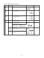
Bypass, capacity control
• Solenoid valve consists of bypass solenoid valve (SV1, SV2) bypassing between high pressure side and low
pressure sides. The following operation will be provided.
1)
Bypass solenoid valves SV1 and SV2 (both “open” when turned on)
• PURY-200·250TUM
SV1
SV2
Item
ON (Open)
OFF (Close)
ON (Open)
OFF (Close)
When starting compressor
Turned on for 4 minutes
Turned on for 4 minutes
After thermost “ON is returned
and after 3 minutes restart
Turned on for 4 minutes
Turned on for 4 minutes
When compressor stops in
cooling or heating mode
Always turned on
–
Turned on for 3 minutes
–
During defrosting operations
Always turned on
Always turned on.
During oil recovery operations
Always turned on.
Always turned on.
During 20Hz operations, at
fall in low pressure or low
pressure saturation temperature. (3minutes or more after
starting)
–
After operation stops
When high pressure rises
(Pd)
When Pd reaches
2.70MPa (391psi) or
more
When high pressure rises
(Pd) during 20Hz operations
(3 minutes after starting)
When Ps is 0.15MPa
(21.3psi) or less
When Pd is 2.35MPa
(341psi) and after 30
seconds
When Pd reaches 2.5MPa When Pd is 2.30MPa
(377psi) or more
(334psi) and after 30
seconds
Turned on when high
pressure (Pd) exceeds
pressure limit
–
When Ps is 0.25MPa
(35.6psi) or more
When high pressure (Pd)
is 1.96MPa (284psi) or
less
When temp. exceeds
When discharge temp. is
130˚C (266˚F) and Pb
115˚C (239˚F) or less
reaches 1.47MPa (213psi)
or more
When discharge temperature
rises
(3 minutes after starting)
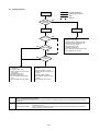
Compressor
Bypass
solenoid
valve (SV1)
Start
(4-minute)
Thermo.
OFF
Thermo.
ON
Defrosting time
(*1)
(2-minute)
(4-minute)
–34–
Stop
(3-minute)
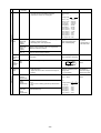
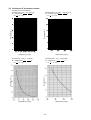
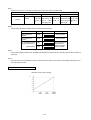
(4) Frequency control
• Depending on capacity required, capacity control change and frequency change are performed to keep constant
evaporation temperature in cooling operations, and high pressure saturation temperature in heating operation.
• Frequency change is performed at the rate of 2Hz/second across 20 ~ 105Hz range.
1)
Frequency control starting
• 60Hz is the upper limit for 3 minutes after starting.
• 75Hz is the upper limit within 30 minutes at the first starting compressor after turning on power source.
2)
Pressure limit
The upper limit of high pressure (Pd) is set for each frequency.
When the limit is exceeded, frequency is reduced every 10 seconds.
(Frequency decrease rate (Hz) : 22% of the present value)
<80>
<100>
3)
Discharge temperature limit
Discharge temperature (Td) of compressor is detected during operation. If the upper limit is exceeded, the frequency
is reduced. (Change rate : 5% of the present value)
• 30 seconds after starting compressor, control is performed every minute.
• Operation temperature is 130˚C (266˚F).
4)
Periodical frequency control
Frequency controll is periodically performed except for the frequency controls at operation start, status change, and
protection.
1 Cycle of periodical frequency control
Periodical frequency control is performed every minute after the time specified below has passed.
• 20 sec after starting compressor or finishing defrostoing operations
• 20 sec after frequency control by discharge temperature or pressure limit
2 Amount of frequency change
The amount of frequency change is controlled corresponding to evaporation temperature and high pressure
saturation temperature.
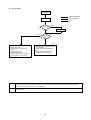
3 Back up of frequency control by bypass valve
During 20Hz operations, frequency is backed up by turning on (opening) bypass valve (SV2).
• Cooling
During 20Hz operations 3 minutes after starting compressor, bypass valve is turned on when,
Ps is 0.15MPa (21.3psi) or less and turned off when Ps is 0.25MPa (35.6psi) or more.
• Heating
During 20Hz operations 3 minutes after starting compressor, SV2 turned on when high pressure (Pd) exceeds
pressure limit and turned off when Pd falls to 1.96MPa (284psi) or less.
ON
▼
▼
OFF
0.15MPa
(21.3psi)
OFF
0.25MPa
(35.6psi)
▼
ON
▼
1.96MPa
(284psi)
–35–
2.65MPa
(384psi)
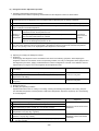
(5) Oil return control (Electronic expansion valve <SLEV>)
• Oil return LEV (SLEV) opening is dependent on compressor frequency and ambient temperature.
• SLEV is closed (0) when compressor stops, and SLEV is set (64) for 10 minutes after starting compressor.
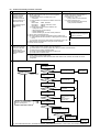
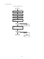
(6) Defrost operation control
1) Starting of defrost operations
• After integrated 50 minutes of compressor operations, defrosting operations start when –6˚C (21˚F) or less of
piping temperature (TH7) is detected for 3 consecutive minutes.
• Forcible defrosting operations start by turning on forcible defrost switch (SW2-7) if 3 minutes have already elapsed
after compressor start or completion of defrosting operations.
2)
Completion of defrosting operations
Defrosting operations stop when 10 minutes have passed since start of defrosting operation, or piping temperature
(TH5) reaches 8˚C (46˚F) or more.
(Defrosting operations do not stop for 4 minutes after starting, except when piping temperature exceeds (TH5 and
TH7) 20˚C (68˚F) and 0.98MPa (142psi).
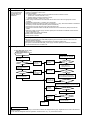
3)
Defrosting prohibition
Defrosting operations do not start during oil recovery, and for 10 minutes after starting compressor.
4)
Trouble during defrosting operations
When trouble is detected during defrosting operations, the defrosting operations stop, and defrosting prohibition
time decided by integrated operation time of compressor is set to be 20 minutes.
5)
Change in number of operating indoor units during defrosting operations
• In case number of operating indoor units changes during defrosting operations, the defrosting operations continue,
and control of unit number change is performed after the defrosting operations are finished.
• Even in case all indoor units stop or thermostat is turned off during defrosting operations, the defrosting operations
do not stop until expected defrosting activities are completed.
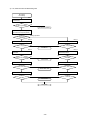
(7) Control of liquid level detecting heater
Detect refrigerant liquid level in accumulator, and heat refrigerant with liquid level heater for judging refrigerant
amount. 6 steps of duty control is applied to liquid level heater depending on frequency and outdoor air temperature,
1minute after starting compressor.
(8) Control of outdoor unit fan and outdoor unit heat exchanger capacity
1) Control system
Depending on capacity required, control outdoor fan flow rate with phase control, for maintaining evaporation
temperature (0˚C (32˚F)) in cooling operations, and high pressure saturated temperature (49˚C (120˚F)) in heating
operations.
2) Control
• Outdoor unit fan stops when compressor stops.
• Fan is in full operation for 5 seconds after starting.
• Outdoor unit fan stops during defrosting operations.
–36–
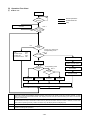
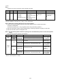
[2] Control of BC Controller
(1) Control of SVA, SVB and SVC
SVA, SVB and SVC are turned on and off depending on connection mode.
Mode
Cooling
Heating
Stop
Defrost
ON
OFF
OFF
OFF
SVB
OFF
ON
OFF
OFF
SVC
ON
OFF
OFF
OFF
Connection
SVA
(2) Control of LEV
LEV opening (sj) is controlled corresponding to operation mode as follows:
Operation mode
Cooling-only
LEV1
2000
LEV3
Superheat
control *1
Heating-only
Cooling-main
(Number of pulse)
Heating-main
• Liquid level
60
control *3
Differential
Differential
• Differential
Pressure control
Pressure control
pressure control
*2
*2
*2
60
Stop
2000
60
Control every minute so that superheat amount detected by bypass inlet and oulet
temperatures (TH12, TH15) stay in the specified range.
*1
Superheat
control
*2
Control every minute so that detected differential pressure (PS1, PS3) stay in the
Differential
pressure control specified range.
*3
–
60 or more pulses are sometimes detected because of rise in liquid side pressure (PS1).
* The above parts of BC controllers are color-corded and shown with the name plate inside the BC controller unit.
–37–
[3] Operation Flow Chart
(1) Outdoor unit
Start
NO
Normal operations
Trouble observed
Stop
Breaker
turned on
YES
“HO” blinks on the remote
controller
Note : 1
NO
Set indoor address No. to remote
controller
YES
Fan
1.
2.
3.
4.
52C
Inverter output
Outdoor fan
All solenoid valve
Operation
mode
OFF
0Hz
Stop
OFF
Error mode
Cooling-only, Heating-only,
Cooling/heating mixed
Note : 2
YES
Error stop
NO
52C ON
Error code blinks on the
outdoor controller board
Note : 3
Cooling/heating mixed
Operation
mode
Cooling (Coolingonly) operations
Note : 4
Operation
mode
Heating (Heatingonly) operations
Cooling-main
operations
Error command to
BC controller
Error code blinks on the
remote controller
Heating-main
operations
Operation mode command to (BC controller) outdoor unit
Note : 1
For about 3 minutes after turning on power source, address and group information of outdoor unit, BC, controller indoor unit,
and remote controller are retrieved by remote controller, during which “HO” blinks on and off on remote controller. In case
indoor unit is not grouped to remote controller, “HO” display on remote controller continues blinking even after 3 minutes after
turning on power source.
Note : 2
Two trouble modes included indoor unit side trouble, (BC controller trouble) and outdoor unit side trouble. In the case of indoor
unit side trouble, error stop is observed in outdoor unit only when all the indoor units are in trouble. However, if one or more
indoor units are operating normally, outdoor unit shows only LED display without undergoing stop.
Note : 3 Operation mode conforms to mode command by BC controller.
Note : 4
In case BC controller issues cooling/heating mixed operation mode, outdoor unit decides operation mode of cooling-main
operation or heating-main operation.
–38–
(2) BC controller
Start
NO
Normal operations
Trouble observed
Stop
Breaker
turned on
YES
NO
Operation
command
YES
1. Operation mode judgement
(cooling-only, heating-only,
cooling/heating mixed)
2. Transmission to outdoor unit
Receiving operation mode
command from outdoor unit
Note : 1
Error mode
YES
NO
Error stop
Cooling/heating mixed
Fan
Operation mode
Error code blinks on the
outdoor controller board
Operation mode
Solenoid valve OFF,
LEV fully closed.
Error command to
BC controller
Operation mode
Error code blinks on the
remote controller
Cooling-only
operations
Note : 1
Heating-only
operations
Cooling-main
operations
Heating-main
operations
Two error modes include indoor unit side trouble, BC controller trouble, and outdoor unit side trouble. In the case of indoor
unit side trouble, error stop is observed in the concerned indoor unit only, and in the cases of BC controller and outdoor unit
side troubles, error stop is observed in all the indoor units, BC controller, and outdoor unit.
–39–
(3) Indoor unit
Start
Breaker
turned on
Normal operations
Trouble observed
Stop
NO
YES
Operation SW
turned on
YES
NO
Note :1
1. Protection function
self-holding cancelled.
2. Indoor unit LEV fully
closed.
Remove controller
display extinguished
Note :2
Error mode
NO
YES
Operation mode
Error stop
Error code blinks on
the remote controller
Cooling mode
Error command
to outdoor unit
Cooling
display
Heating
mode
Dry mode
Cooling/heating
automatic mode
Fan mode
Dry display
Cooling/heating
automatic display
Fan display
FAN stop
YES
Drain pump
ON
NO
Indoor unit LEV
fully closed
Note :1
3-minute drain
pupm ON
Heating
display
Note :3
Prohibition
YES
Prohibition
NO
NO
Cooling
operations
Heating
operations
Error code
blinks on the
outdoor
controller board
YES
Note :3
Prohibition
NO
Dry
operation
YES
Note :3
Prohibition
YES
NO
Cooling/heating
automatic
operations
Fan
operations
Prohibition “Remote
controller blinking”
Note : 1 Indoor unit LEV fully closed : Opening 41
Note : 2
Two error modes include indoor unit trouble, (BC controller trouble) and outdoor unit side trouble. In the case of indoor unit
trouble, error stop is observed in the concerned indoor unit only, and in the cases of (BC controller and) outdoor unit side
troubles, error stop is observed in all the indoor units connected.
Note : 3
“Prohibition” status is observed (when several indoor units are connected to one connection, of BC controller and) when
connection mode is different from indoor unit operation mode. (Operation mode display on the remote controller blinks on
and off, fan stops, and indoor unit LEV is fully closed.)
–40–
(4) Cooling operation
Cooling operation
Normal operations
Test run
Stop
4-way valve OFF
Indoor unit fan
operations
Test run start
YES
NO
NO
Thermostat ON
YES
YES
3-minute
restart
prevention
NO
1. Inverter output 0Hz
2. Indoor unit LEV, oil return LEV,
Subcool coil bypass LEV fully
closed
3. Solenoid valve OFF
4. Outdoor unit fan stop
5. BC controller solenoid valve OFF
6. BC controller LEV fully closed
1. Inverter frequency control
2. Indoor unit LEV, oil return LEV
control
3. Solenoid valve control
4. Outdoor unit fan control
5. BC controller solenoid valve control
6. BC controller LEV control
–41–
(5) Heating operation
Heating operation
Note : 1
Note : 2
Defrosting
operation
Normal operations
Defrosting operations
Stop
Test run
YES
NO
4-way valve OFF
4-way valve ON
Test run start
YES
NO
NO
Thermostat ON
YES
YES
1. Indoor unit fan stop
2. Inverter defrost frequency control
3. Indoor unit LEV fully opened, oil
return LEV fully closed
4. Solenoid valve control
5. Outdoor unit fan stop
6. BC controller solenoid valve control
7. BC controller LEV control
3-minute
restart
prevention
NO
1. Indoor unit fan very low speed
operations
2. Inverter output 0Hz
3. Indoor unit LEV, oil return LEV
fully closed
4. Solenoid valve OFF
5. Outdoor unit fan stop
6. BC controller solenoid valve
OFF
7. BC controller LEV fully closed
Note : 1
1. Indoor and outdoor unit fan
control
2. Inverter frequency control
3. Indoor unit LEV, oil return LEV
control
4. Solenoid valve control
5. BC controller solenoid valve
control
6. BC controller LEV control
When outdoor unit starts defrosting, it transmits defrost operations command to (BC controller and) indoor unit, and the
indoor unit starts defrosting operations.
Similarly when defrosting operation stops, indoor unit returns to heating operation after receiving defrost end command of
outdoor unit.
Note : 2 Defrosting start condition : After integrated 50 minutes of compressor operations, and –6˚C (21˚F) or less outdoor unit coil
temperature. (TH7)
Defrosting end condition : After 15 minutes of defrosting operation or the outdoor unit coil temperature (TH5 and TH7)
having risen to 8˚C (46˚F) or more.
–42–
(6) Dry operation
Dry operations
Normal operations
Thermostat ON
Stop
4-way valve OFF
Test run start
YES
Note : 2
Thermostat ON
NO
NO
Inlet temp.
18˚C (64˚F)
YES
Note : 1
1. Indoor unit fan stop
2. Inverter output 0Hz
3. Indoor unit LEV, oil return LEV
closed
4. Solenoid valve OFF
5. Outdoor unit fan stop
6. BC controller solenoid valve OFF
7. BC controller LEV fully closed
1. Outdoor unit (Compressor) intermittent operations
2. Indoor unit fan intermittent operations
YES
(Synchronized with compressor :
low speed, OFF operations)
Note : 1 When indoor unit inlet temperature exceeds 18˚C (64.4˚F), outdoor unit (compressor) and indoor unit fan start intermittent
operations synchronously. Operations of outdoor unit, BC controller, indoor unit LEV and solenoid valve accompanying
compressor are the same as those in cooling operations.
Note : 2
Thermostat is always kept on in test run, and indoor and outdoor unit intermittent operation (ON) time is a little longer than
normal operations.
–43–
[4] List of Major Component Functions
Name
Symbol
(function)
Application
Specification
Compres- MC
sor
Adjust refrigerant circulation by controlling operating
frequency and capacity control valve with operating
pressure.
High
pressure
sensor
1) High press. detection.
2) Frequency control and high pressure protection
63HS
Low pressure shell scroll type
with capacity control mechanism
Winding resistance:
Each phase 0.388Ω
(20˚C(68˚F))
Pressure
0~2.94MPa
(0~426psi)
Vout 0.5~3.5 V
Gnd (black)
Vout (white)
Vc (DC5V) (red)
63HS
Connector
Low
pressure
sensor
63LS
1) Detects low pressure
2) Calculates the refrigerant circulation configuration.
3) Protects the low pressure
Pressure
0~0.98MPa
(0~142psi)
Vout 0.5~3.5 V
63LS
Outdoor unit
Connector
Pressure
switch
63H
Thermistor TH1
(discharge)
Gnd (black)
Vout (white)
Vc (DC5V) (red)
1) High pressure detection
2) High pressure protection
Setting 2.94MPa (426psi)
OFF
Continuity check
1) Discharge temperature detection
2) High pressure protection
R120=7.465kΩ
B25/120=4057
Resistance value
check
20˚C (68˚F)
30˚C (86˚F)
40˚C (104˚F)
50˚C (122˚F)
60˚C (140˚F)
TH5
(piping
temperature)
Check method
: 250kΩ
: 160kΩ
: 104kΩ
: 70kΩ
: 48kΩ
70˚C (158˚F)
80˚C (176˚F)
90˚C (194˚F)
100˚C (212˚F)
110˚C (230˚F)
:
:
:
:
:
34kΩ
24kΩ
17.5kΩ
13.0kΩ
9.8kΩ
Rt = 7.465exp
{4057( 1 273+t
1
)}
273+120
1) Frequency control
R0=15kΩ
2) Defrost control and liquid level detection at heating B0/100=3460
Rt =
1
15exp{3460(
273+t
TH6 (outdoor 1) Outdoor air temperature detection
0˚C (32˚F)
air tempera- 2) Fan control, liquid level heater, and opening setting 10˚C (50˚F)
for oil return
ture)
20˚C (68˚F)
25˚C (77˚F)
30˚C (86˚F)
40˚C (104˚F)
–44–
-
1
)}
273+0
: 15kΩ
: 9.7kΩ
: 6.4kΩ
: 5.3kΩ
: 4.3kΩ
: 3.1kΩ
Name
Symbol
(function)
Indoor unit
Outdoor unit
Thermistor THHS
Application
Specification
1) Detects the inverter cooling fin temperature.
2) Provides inverter overheating protection.
3) Controls the control box cooling fan.
R50=17kΩ
B25/50=4170
Rt =
17exp{4170(
1
1
)}
273+t 273+50
-20˚C (-4˚F) :
-10˚C (14˚F) :
0˚C (32˚F)
:
10˚C (50˚F) :
20˚C (68˚F) :
30˚C (86˚F) :
40˚C (104˚F) :
50˚C (122˚F) :
60˚C (140˚F) :
70˚C (158˚F) :
80˚C (176˚F) :
90˚C (194˚F) :
100˚C (212˚F) :
Solenoid
valve
SV1
(discharge suction
bypass)
1) High/low press. bypass at starting/stopping and
capacity control at low load
2) Discharge press. rise suppression
SV2
(discharge suction
bypass)
Capacity control and high press. rise suppression
(backup for frequency control)
SV3 ~ 6
Control of heat exchanger capacity.
Linear
SLEV
expansion
valve
Adjustment of liquid refrigerant (oil) return foam
accumulator
Liquid
level
detection
switch
Detection of refrigerant liquid level in accumulator
LD1
LD2
Check method
605.0kΩ
323.3kΩ
180.9kΩ
105.4kΩ
63.8kΩ
39.9kΩ
25.7kΩ
17.0kΩ
11.5kΩ
8.0kΩ
5.7kΩ
4.1kΩ
3.0kΩ
AC 208~230V
Open at energizing and
close at deenergizing
• Continuity check
by tester
• Temperature of
inlet and outlet.
DC12V stepping motor drive
Valve opening 0~480 pulse
LD2
LD1
5.1k‰
5.1k‰
Resistance value
check
2 3 4
CN05
Linear
LEV
expansion
valve
1) Adjust superheat of outdoor unit heat exchanger
outlet at cooling.
2) Adjust subcool of indoor unit heat exchanger at
heating.
DC12V
Opening of stepping motor
driving valve
41~2,000 pulses
Continuity check
with tester for
white-red-orange
yellow-brown-blue
Thermistor TH21
(inlet air
temperature)
Indoor unit control (thermostat)
R0 = 15kΩ
B0/100 = 3460
Resistance value
check
1) Indoor unit control (freeze prevention, hot adjust,
etc.)
2) LEV control in heating operation (Subcool detection)
Rt =
1
15exp {3460 (
TH22
(piping
temperature)
TH23
(gas side
piping
temperature)
LEV control in cooling operation
(Superheat detector)
–45–
1
)}
273+t 273+0
0˚C (32˚F)
10˚C (50˚F)
20˚C (68˚F)
25˚C (77˚F)
30˚C (86˚F)
40˚C (104˚F)
: 15kΩ
: 9.7kΩ
: 6.4kΩ
: 5.3kΩ
: 4.3kΩ
: 3.1kΩ
Name
Pressure
sensor
Symbol
(function)
PS1
Application
Specification
1) Liquid pressure (high-pressure) detection
2) LEV control
PS1
PS3
Connector
PS3
Thermistor TH11
(liquid inlet
temperature)
1) Intermediate pressure detection
2) LEV control
LEV control (liquid refrigerant control)
BC controller
TH12
LEV control (superheat control)
(bypass outlet
pressure)
Solenoid
valve
TH16
(bypass inlet
temperature)
LEV control (subcool control)
SVA
Supplies refrigerant to cooling indoor
unit.
SVB
Supplies refrigerant to heating indoor
unit.
SVC
Supplies refrigerant to cooling indoor
unit.
Electronic LEV1
expansion
valve
LEV3
Liquid level control
pressure control
Pressure
0~2.94MPa
(0~426psi)
Vout 0.5~3.5 V
Gnd (black)
Vout (white)
Vc (DC5V) (red)
R0=15kΩ
B0/100=3460
Rt =
1
1
15exp{3460( 273+t - 273+0 )}
0˚C (32˚F)
10˚C (50˚F)
20˚C (68˚F)
25˚C (77˚F)
30˚C (86˚F)
40˚C (104˚F)
TH15
LEV control (superheat control)
(bypass outlet
temperature)
Check method
: 15kΩ
: 9.7kΩ
: 6.4kΩ
: 5.3kΩ
: 4.3kΩ
: 3.1kΩ
AC 208~230V
Open when energized
Closed when de-energized
Continuity check
by a tester
12V DC stepping motor drive Same as LEV of
0 to 2000 valve opening
indoor unit.
pulse
Liquid level control
pressure control
–46–
[5] Resistance of Temperature Sensor
Thermistor for low temperature
Thermistor Ro= 15kΩ ± 3% (TH3 ~ 9)
1
1
)}
Rt = 15exp {3460 (
273+tc
273+0
9
∗˚F= × ˚C + 32
Thermistor R120 = 7.465kΩ ± 2% (TH1, 10)
1
1
Rt = 7.465exp {4057 ( 273+tc - 273+120 )}
9
∗˚F= × ˚C + 32
5
50
25
40
20
Resistance (kΩ)
Resistance (kΩ)
5
30
20
15
10
5
10
0
0
90
[194]
Ð20 Ð10 0 10 20 30 40 50
[Ð4] [14] [32] [50] [68] [86] [104] [122]
Temperature (˚C)[˚F]
100
[212]
110
[230]
Temperature (˚C)[˚F]
Thermistor Ro = 33kΩ ± 1% (TH2)
1
1
Rt = 33exp {3965 ( 273+tc - 273+0 )}
9
∗˚F= × ˚C + 32
Thermistor R50 = 17kΩ ± 2% (THHS)
1
1
Rt = 17exp {4170 (273+tc - 273+50 )}
9
∗˚F= × ˚C + 32
5
Resistance (kΩ)
Resistance (kΩ)
5
Temperature (˚C)[˚F]
Temperature (˚C)[˚F]
–47–
120
[248]
6 REFRIGERANT AMOUNT ADJUSTMENT
Clarify relationship between the refrigerant amount and operating characteristics of CITY MULTI, and perform service
activities such as decision and adjustment of refrigerant amount on the market.
[1] Refrigerant Amount and Operating Characteristics
The followings are refrigerant amount and operating characteristics which draw special attention.
1
During cooling operations, required refrigerant amount tends to increase (refrigerant in accumulator decreases)
in proportion to increase in the number of operating indoor units. However, the change of increase rate is small.
2
During heating operations, liquid level of accumulator is the highest when all the indoor units are operating.
3
Discharge temperature hardly changes when increasing or decreasing refrigerant amount with accumulator
filled with refrigerant.
During cooling operations, discharge temperature tends to rise at
overload than low temperature.
4
Tendency of
discharge
temperature
During heating operations, discharge temperature tends to rise at low Comparison including
temperature than overload.
control system
The lower the operating frequency is, the higher the discharge
temperature tends to become of deteriorated compressor efficiency.
5
Compressor shell temperature is 20~70 (36~126) degrees higher than low pressure saturation temperature
(Te) when refrigerant amount is appropriate.
→ Judged as over replenishment when temperature difference from low pressure saturation temperature (Te)
is 10 (18) degrees or less.
Note : ˚C Scale (˚F Scale)
[2] Adjustment and Judgement of Refrigerant Amount
(1) Symptom
The symptoms shown in the table below are the signs of excess or lack of refrigerant amount. Be sure to adjust the
amount of refrigerant in refrigerant amount adjustment mode, by checking operation status, judging refrigerant
amount, and performing selfdiagnosis with LED Dip s/w 1, 1-10, for overall judgement of excess or lack of refrigerant amount.
1
Emergency stop at 1500 remote controller display (excessive
refrigerant replenishment)
2
Operating frequency does not fully increase, thus resulting in
insufficient capacity
3
Emergency stop at 1102 remote controller display (discharge
temperature trouble)
4
Emergency stop occurs when the remote control display is at
1501. (insufficient refrigerant)
Excessive refrigerant replenishment
Insufficient refrigerant replenishment
–48–
Insufficient refrigerant
(2) Refrigerant Volume Adjustment Operation
1) Operating Characteristics Refrigerant Volume
Characteristic items related to operating characteristics and the refrigerant volume are shown below.
1
If the number of indoor units in operation increases during cooling, the required volume of refrigerant tends to
increase (the amount of refrigerant in the accumulator tends to decrease), but the change is minimal.
2 The liquid level in the accumulator is at its highest when all the indoor units are operating during heating.
3 If there is refrigerant in the accumulator, even if the volume of refrigerant is increased or decreased, there is practically no change in the outlet temperature.
During cooling, the discharge temperature rises more easily when there is an
overload than when the temperature is low.
Tendency of
4 discharge
Temperature
During heating, the discharge temperature rises more easily when the temperature is low than when there is an overload.
Comparison
when control is
included.
The lower the operating frequency, the less efficient the compressor is, making it
easier for the discharge temperature to rise.
5 The compressor shell temperature becomes 20~70 (36~126) deg. higher than the low pressure saturation temperature (TH2) if the refrigerant volume is appropriate. If the difference with the low pressure saturation temperature
(TH2) is 10 (18) deg. or less, it can be judged that the refrigerant is overcharged.
Note : ˚C Scale (˚F Scale)
2) Adjusting and Judging the Refrigerant Volume
1 Symptoms
Overcharging with refrigerant can be considered as the cause of the following symptoms. When adjusting the
refrigerant volume, be sure that the unit is in the operating condition, and carry out refrigerant volume judgment and
self-diagnosis by the LED’s, judging overall whether the volume of refrigerant is in excess or is insufficient. Perform
adjustments by running the unit in the refrigerant volume adjustment mode.
1
Emergency stop occurs when the remote control display is at 1500 (refrigerant
overcharge).
Refrigerant overcharge
2 The operating frequency doesn’t rise high enough and capacity is not achieved.
3 Emergency stop occurs when the remote control display is at 1102 (outlet
temperature overheating).
4 Emergency stop occurs when the remote control display is at 1501 (insufficient
refrigerant).
Insufficient refrigerant
Insufficient refrigerant
2 Refrigerant Volume
a Checking the Operating Condition
Operate all the indoor units on cooling or on heating, checking the discharge temperature, sub-cooling, low pressure saturation temperature, inlet temperature, shell bottom temperature, liquid level, liquid step, etc. and rendering
an overall judgment.
Condition
Judgement
1
Outlet temperature is high. (125°C (257˚F) or higher)
2
Low pressure saturation temperature is extremely low.
3
Inlet superheating is high (if normal, SH = 20 (36) deg or lower).
4
Shell bottom temperature is high (the difference with the low pressure saturation
temperature is 70 (126) deg. or greater)
5
Shell temperature is low (the difference with the low pressure saturation temperature is 10 (18) deg. or lower).
6
Dischange superheating is low (if normal, SH = 20 (36) deg or higher).
Note : ˚C Scale (˚F Scale)
–49–
Refrigerant volume tends toward
insufficient.
Rifrigerant volume tends toward
overcharge.
b
Check the refrigerant volume by self-diagnosis using the LED.
Set the self-diagnosis switch (SW1) as shown below and check the past information (history) concerning the
refrigerant volume.
1 2 3 4 5 6 7 8 9 10
Set SW1 as shown in he figure at right.
ON
If LD8 lights up, it indicates the refrigerant charge abnormal delay state just before emergency stop due to refrigerant overcharge (1500).
3 Additional Refrigerant Charge Volume
At the time of shipping from the factory, the outdoor unit is charged with the amount of coolant shown in the following table, but since no extension piping is included, please carry out additional charging on-site.
Outdoor Unit Model Name
Refrigerant Charge Volume
PURY-80TMU
10.0kg
(22lb 1oz)
PURY-100TMU
11.0kg
(26lb 8oz)
Calculation Formula
Calculate the additional refrigerant volume by calculating the size of the extension liquid piping and its length units (m)[ft].
Additional Refrigerant Volume
(kg) = (0.16 × L1) + (0.06 × L2) + (0.024 × L3) + A
[ (oz) = (1.72 × L1) + (0.65 × L2) + (0.20 × L3) + A ]
L1:
L2:
L3:
A:
Length of ø12.7 (3/4") liquid pipe (m) [ft]
Length of ø9.52 (3/8") liquid pipe (m) [ft]
Length of ø6.35 (1/4") liquid pipe (m) [ft]
refer to the calculation table.
In the calculation results, round up fractions smaller than 0.01 kg. (Example: 18.54 kg → 18.6 kg)
1.0oz (653.97oz → 654oz)
(α Calculation Table)
Total Capacity of
Connected Indoor Units
32
33 ~64
65~130
A
kg (oz)
1.0 (36)
1.5 (53)
2.0 (71)
–50–
(3) Refrigerant Amount Adjustment Mode Operations
1 Procedure
Depending on the operating conditions, it may be necessary either to charge with supplementary refrigerant, or to
drain out some, but if such a case arises, please follow the procedure given below flow chart.
Notes 1
As the refrigerant volume can not be adjusted in the heating mode, retrieve the refrigerant, evacuate air and then fill the specified volume of refrigerant if it is necessary to adjust the refrigerant
volume in the winter season.
Notes 2
A refrigerant volume adjustment performed in the cooling mode must be done with a gauge reading of 1.27MPa
(184.8psi) or higher.
If the pressure does not reach this guage reading the refrigerant cannot be collected halfway.
Therefore, collect used refrigerant and evacuate the unit completely, and then fill new refrigerant up to a specified
quantity.
Notes 3
Judgment by the AL is at best only a rough guideline. Please do not add refrigerant based on the
AL reading alone. (Be sure to obtain calculations of the correct amount before adding refrigerant.)
When supplementing the refrigerant volume, please be careful to charge with liquid refrigerant.
Notes 4
TH1
SC11
1 2 3 4 5 6 7 8 9 10
ON
1 2 3 4 5 6 7 8 9 10
ON
SC16
Pd (High pressure)
1 2 3 4 5 6 7 8 9 10
ON
1 2 3 4 5 6 7 8 9 10
ON
–51–
YES
Adjustment starts.
NO
Start cooling operation of all indoor
units in a test run mode. Note 1
Note 1) As the refrigerant volume can not be adjusted in the heating mode,
retrieve the refrigerant, evacuate air and then fill the specified
volume of refrigerant if it is necessary to adjust the refrigerant
volume in the winter season.
Has the
compressor been
operated for more than
30min?
Was the operation
condition stabilized?
Is the
thermostat turned
on/off in order for the indoor
unit to prevent from
frosting?
The high pressure
> 1.27MPa (185psi)
*Operate for 5 minutes after adjusting the refrigerant and make a judgement.
Stop the refrigerant volume adjustment
and retrieve the refrigerant. After
evacuating air, fill the specified volume
of refrigerant.
Fill refrigerant little by little from the
low-pressure side service port.
TH1 ≤ 115˚C? (239˚F)
Are all indoor
units SHs more
than 2 (3.6) deg?
Is the LEV opening
degree stable when SH
< 2 (3.6) deg?
*Operate for 5 minutes after adjusting the refrigerant and make a judgement.
Fill refrigerant little by little from the
low-pressure side service port.
5deg ≤ SC11?
Note 2
*Operate for 5 minutes after adjusting the refrigerant and make a judgement.
10 (18) ≤ SC16 ≤ 30(54) deg?
Note 3
30 (54) deg < SC16?
Retrieve the refrigerant little by little
from the low-pressure side service
port.
Fill refrigerant little by little from the
low-pressure side service port.
*Operate for 5 minutes after adjusting the refrigerant and make a judgement.
TH1 ≤ 110˚C? (230˚F)
Fill refrigerant little by little from the
low-pressure side service port.
Note 2) SC11 : Liquid refrigerant sub-cool for BC controller inlet
Note 3) SC16 : Liquid refrigerant sub-cool for BC controller outlet
Adjustment completed.
Note 4) ˚C Scale (˚F Scale)
–52–
1 Time required for recovering refrigerant from low pressure service port (minute)
Low pressure
MPa (psi)
0.34~0.44
(49.8~64)
0.44~0.54
(64~78.2)
0.54~0.74
(78.2~106.7)
1 (35.2)
4.0
3.5
3.5
2 (70.4)
8.0
7.0
6.5
3 (105.6)
12.0
10.5
10.0
4 (140.8)
16.0
14.0
13.0
5 (176)
20.0
18.0
16.5
6 (211.2)
24.0
21.5
19.5
7 (246.4)
28.0
25.0
23.0
8 (281.6)
32.0
28.5
26.0
9 (316.8)
36.0
32.0
29.5
10 (352)
40.0
35.5
32.5
11 (388.8)
44.0
39.0
36.0
Refrigerant amount
to be drawn out kg (oz)
2 Additional evacuation and refrigerant replacement
R2 series has unique refrigerant circuit structure which makes possible 2-pipe cooling-heating simultaneous
operations. Therefore, in the case of total replacement or replenishment of refrigerant in this system, the following
evacuation and refrigerant replenishment procedures are required.
1 Perform evacuation by connecting to system analyzer joint of service port of high pressure ball valve and high
pressure charge plug, and joint of service port of low pressure ball valve and low pressure charge plug.
2 Perform refrigerant charge from low pressure circuit only, after finishing evacuation, closing vacuum pump valve,
shutting off high pressure circuit of system analyzer, and opening valve of refrigerant cylinder.
(In case service port of ball valve and charge plug can not be joined as shown in the figure, use two vacuum
pumps and evacuate high pressure side and low pressure side circuits separately.)
Note 1: Though refrigerant gas itself is harmless, airtight room should be opened before gas release for preventing
oxygen shortage.
2: When releasing gas, use blotting paper, etc. so that oil spouted with the gas does not spread out.
D
E
J
LO
F
K
HI
L
N
M
A
S
O
T
P
R
C
G
B
H
I
A
B
C
D
E
F
G
H
I
J
K
Ball valve of the high pressure side
Service port
Ball valve of the low pressure side
Charge plug
High pressure
Low pressure
Evacuation
Evacuation
Replenish of refrigerant
System analyzer
Lo knob
L
M
N
O
P
R
S
T
–53–
Hi knob
3-way joint
Valve
Valve
Flon 22 cylinder
Scale
Vacuum pump
A high-precision gravimeter measurable up to 0.1kg
(3.5oz) should be used. If you are unable to prepare
such a high-precision gravimeter, you may use a
charge cylinder.
7 TROUBLESHOOTING
[1] Principal Parts
Pressure Sensor
(1) Judging Failure
1) Check for failure by comparing the sensing pressure according to the high pressure/low pressure pressure sensor
and the pressure gauge pressure.
Turn on switches 1, 3, 5, 6 (High) and 2, 4, 5, 6 (Low) of the digital display select switch (SW1) as shown below, and
the sensor pressure of the high pressure/low pressure sensors is displayed digitally by the light emitting diode LD1.
1 2 3 4 5 6 7 8 9 10
High Pressure
ON
1 2 3 4 5 6 7 8 9 10
Low Pressure
ON
1
In the stopped condition, compare the pressure readings from the gauge and from the LD1 display.
(a) If the gauge pressure is 0~0.098MPa (0~14.2 psi), the internal pressure is dropping due to gas leakage.
(b) If the pressure according to the LD1 display is 0~0.098MPa (0~14.2 psi), there is faulty contact at the connector, or it is disconnected. Proceed to 4.
(c) If the pressure according to the LD1 display is 3.14MPa (455 psi) or higher, proceed to 3.
(d) If other than (a), (b) or (c), compare the pressure readings during operation. Proceed to 2.
2
Compare the pressure readings from the gauge and from the LD1 display while in the running condition.
(a) If the difference between the two pressures is within 0.098MPa (14.2 psi), both the affected pressure sensor
and the main MAIN board are normal.
(b) If the difference between the two pressures exceeds 0.098MPa (14.2 psi), the affected pressure sensor is faulty
(deteriorating performance).
(c) If the pressure reading in the LD1 display does not change, the affected pressure sensor is faulty.
3
Disconnect the pressure sensor from the MAIN board and check the pressure according to the LD1 display.
(a) If the pressure is 0~0.098MPa (0~14.2 psi) on the LD1 display, the affected pressure sensor is faulty.
(b) If the pressure is 3.14MPa (455 psi) (in the case of the low pressure sensor, 0.98MPa (142 psi)) or higher, the
MAIN board is faulty.
4
Disconnect the pressure sensor from the MAIN board and short out the No. 2 and No. 3 pins of the connector
(63HS, 63LS), then check the pressure by the LD1 display.
(a) If the pressure according to the LD1 display is 3.14MPa (455 psi) (in the case of the low pressure sensor,
0.98MPa (142 psi)) or higher, the affected pressure sensor is faulty.
(b) If other than (a), the MAIN board is faulty.
2) Pressure sensor configuration.
The pressure sensors are configured in the circuit shown in the figure at right. If DC 5 V is applied between the red
and black wires, a voltage corresponding to the voltage between the white and black wires is output and this voltage
is picked up by the microcomputer. Output voltages are as shown below.
High Pressure
Low Pressure
0.1 V per 0.098MPa (14.2 psi)
0.3 V per 0.098MPa (14.2 psi)
63HS/
63LS
Vout 0.5~3.5 V
Connector
GND (Black)
Vout (White)
Vcc (DC5V) (Red)
–54–
* Connector connection specifications on the pressure sensor body side.
The connector’s pin numbers on the pressure sensor body side differ from the pin numbers on the main circuit board
side.
Sensor Body Side
Pin1
Pin2
Pin3
Vcc
Vout
GND
MAIN Board Side
Pin3
Pin2
Pin1
Solenoid Valve (SV1~6)
Check if the control board’s output signals and the operation of the solenoid valves match.
Setting the self-diagnosis switch (SW1) as shown in the figure below causes the ON signal of each relay to be output to
the LED’s.
Each LED shows whether the relays for the following parts are ON or OFF. When a LED lights up, it indicates that the
relay is ON.
SW1
LED
1
2
3
1 2 3 4 5 6 7 8 9 10
ON
4
5
6
7
SV1
SV2
SV3
SV4
8
1 2 3 4 5 6 7 8 9 10
ON
SV5
SV6
1) In the case of SV1 (Bypass Valve)
(a) When the compressor starts, SV1 is ON for 4 minutes, so check operation by whether the solenoid valve is
emitting an operating noise.
(b) Changes in the operating condition by solenoid valve operation can be confirmed by the temperature of the
bypass circuit and the sound of the refrigerant.
2) In the case of SV2 (Bypass)
(a) SV2 goes ON in accordance with the rise in the high pressure in the cooling mode and heating mode, so check
its operation by the LED display and the operating noise emitted by the solenoid valve.
(Conditions during operation: See Control of Outdoor Unit.)
(b) Changes in the operating condition by solenoid valve operation can be confirmed by the temperature of the
bypass circuit and the sound of the refrigerant.
3) SV3 ~ 6 (Control of heat exchanger capacity)
(a) Operations can be confirmed by LED display and operating sound of solenoid valve, because one or more of
SV3 ~5 are turned on depending on conditions during cooling-only operations.
(b) Operation can be confirmed by LED display and operating sound of solenoid valve, because all of SV3 ~ 5 are
turned on during heating-only operations.
(c) Operations can be confirmed by LED display and operating sound of solenoid valve, because one or more of
SV3 ~6 are turned on depending on conditions during cooling-principal and heating-principal operations.
–55–
(d) The refrigerant flow is as following figure. Hot gas (high pressured) flows in cooling mode and cool gas/liquid
(low pressured) flows in heating mode. Please refer to the Refrigerant Circuit Diagram.
And, ON/OFF of Solenoid valve is depends on the amount of running indoor units, ambient temperature and so
on. So please check by LED Monitor Display.
If the SV coil is taken off, then it is possible to open caps and check plungers. But the special tool which is on
the Service Parts List is needed.
(1 25 ")
32
* Closed torque : 13kg·m (1.3N·m)
(0.958lbFFt)
–56–
Judgment methods and likely failure mode
Caution:
The specifications of the outdoor unit (outdoor LEV) and indoor unit (indoor LEV) differ. For this reason, there are
cases where the treatment contents differ, so follow the treatment specified for the appropriate LEV as indicated in
the right column.
Failure Mode
Microcomputer
driver circuit
failure
Judgment Method
Treatment
1 Disconnect the control board connector and connect
the check LED as shown in the figure below.
Indoor, BC controller
Outdoor
Affected LEV
In the case of driver circuit
failure, replace the control
board.
Indoor
BC controller
Replace the LEV.
Indoor
BC controller
When the base power supply is turned on, the indoor LEV
outputs pulse signals for 10 seconds, the outdoor LEV
outputs pulse signals for 17 seconds, and BC controller
outputs pulse signals for 10-20 seconds.
If the LED does not light up, or lights up and remains on,
the driver circuit is abnormal.
LEV mechanism
is locked.
1 If the LEV is locked up, the drive motor turns with no
load and a small clicking sound is generated.
Generation of this sound when the LEV is fully closed
or fully open is abnormal.
The LEV motor
Measure the resistance between the coils (red - white, red Replace the LEV coils.
coils have a
- orange, brown - yellow, brown - blue) using a tester. They
disconnected wire are normal if the resistance is within 150Ω ± 10%.
or is shorted.
Indoor
BC controller
Fully closed
failure (valve
leaks)
1 If you are checking the indoor unit’s LEV, operate the
indoor unit’s blower and the other indoor units in the
cooling mode, then check the piping temperatures
(liquid pipe temperatures) of the indoor units by the
operation monitor through the heat source unit’s
control board. When the fan is running, the linear
expansion valve is fully closed, so if there is leakage,
the temperature sensed by the
Thermistor
thermistor (liquid pipe temperature
liquid pipe
sensor) will become low. If the
(temperatemperature is considerably low
ture sensor)
compared to the remote control’s
Linear
intake temperature display, it can
Expansion
be judged that there is a fully
Valve
closed failure. In the case of
minimal leakage, it is not necessary to replace the
LEV if there are no other effects.
If there is a large amount of
leakage, replace the LEV.
Indoor
BC controller
Faulty wire
connections in
the connector or
faulty contact.
1 Check for pins not fully inserted on the connector and
check the colors of the lead wires visually.
2 Disconnect the control board’s connector and conduct
a continuity check using a tester.
Check the continuity at the
places where trouble is found.
Indoor
BC controller
–57–
Outdoor LEV (SLEV) Coil Removal Procedure (configuration)
As shown in the figure, the outdoor LEV is made in such a way that the coils and the body can be separated.
Coils
Stopper
Lead Wires
<Removing the Coils>
Fasten the body tightly at the bottom (Part A in the figure) so
that the body will not move, then pull out the coils toward the
top. If they catch on the stopper and are difficult to take out,
turn the coils left and right until the stoppers are free from the
stopper indentations, then pull the coils out.
If you take out the coils only without gripping the body, undue
force will be applied to the piping and the pipe may be bent
over, so be sure to fasten the body in such a way that it will not
move.
–58–
Part A
Check Valves Block
The refrigerant flow in the pipe 6, 7, 8 and 9 are depend on ON/OFF of the SV3, 4, 5 and 6.
Please confirm by LED monitor display.
You can open the cap of valve A, B and C, but 3 types of hexagon socket screw keys. The size is as follows.
* Closed torque : A : 1.7kg·m (0.17N·m) [0.125lbFFt]
B : 20kg·m (2.0N·m) [1.47lbFFt]
C : 13kg·m (1.3N·m) [0.96lbFFt]
1mm = 0.04”
–59–
Intelligent Power Module (IPM)
Measure resistances between each terminal of IPM with tester, and use the results for troubleshooting. Specified
resistance value is dependent on tester type to be used for resistance measurement, because diode inside IPM has
non-linearity, thus difference of impedance and voltage in tester being influential. As the internal impedance of
resistance range of analog tester equals to the center value of meter indication, the affect of internal impedance can
be minimized if the tester having close center value of resistance range. Because internal voltage is normally 1.5V,
the tester to be used for troubleshooting of IPM should satisfy the following conditions.
Internal voltage
1.5V (Power source : one dry cell battery)
Central value of resistance range
10 ~ 40Ω
The measured values for troubleshooting are shown in the table below.
(Use the minimum range for tester resistance range.)
External view
Internal circuit diagram
P
3
1
4
7
10
2
16
Pre-Driver
U
1
6
B
5
P
Pre-Driver
V
4
9
8
N
V
W
U
Pre-Driver
W
7
11
13
Pre-Driver
10
Judged value
14
Tester
+
Tester —
P
P
U
V
W
N
∞
∞
∞
∞
∞
2~
100Ω
2~
100Ω
2~
100Ω
2~
2~
2~
2~
100Ω 100Ω 100Ω 100Ω
U
V
W
N
15
Pre-Driver
Pre-Driver
B
12
∞
∞
N
16
Over heating
protection circuit
Diode stack
Perform continuity check with tester. Judged as normal if the following characteristics are observed.
(Use the minimum range for tester resistance range.)
Tester ⊕
Tester 1
+
–
10~50Ω
∞
2
10~50Ω
∞
3
10~50Ω
∞
+
–
1
∞
10~50Ω
2
∞
10~50Ω
3
∞
10~50Ω
Tester 1
2
Tester ⊕
3
+
1
2
3
—
–60–
(2) Trouble and remedy of remote controller
Symptom
1
Despite pressing of
remote controller
ON/OFF switch,
operation does not
start and there is no
electronic sound.
(No powering signal
appears.)
2
At about 10 seconds
after turning remote
controller operation
switch ON, the
display distinguishes
and the operation
stops.
Cause
Checking method & countermeasure
1) M-NET transmission power source is not supplied
a) Check transmission terminal block of
from outdoor unit.
remote controller for voltage.
1 Main power source of outdoor unit is not
i) In case of 17 ~ 30V
connected.
→ Faulty network remote controller
2 Disconnection of connector on outdoor unit circuit
ii) In case of less than 17V
board.
→ See “Transmission Power Circuit
Main board : CNS1, CNVCC3
(30V) Check Procedure”.
INV board
: CNDC2, CNVCC2, CNL2
G/A board
: CNDC1
3 Faulty power source circuit of outdoor unit.
• Faulty INV board,
• Blown fuse (F1 on INV board)
• Broken diode stack
The cause of 2) and 3) is
• Broken resistor (R1) for rush current protection
displayed with self-diagnosis
2) Short circuit of transmission line.
LED for 7102 error.
3) Erroneous wiring of M-NET transmission line at outdoor unit.
1 Transmission line disconnection or slipping off from terminal
block.
2 Erroneous connection of indoor/outdoor transmission line to TB7.
4) Disconnection of transmission wiring at remote controller.
5) Faulty remote controller.
1) Power source is not fed to indoor unit from transformer.
1 Main power source of indoor unit is not turned on.
2 Disconnection of connector (CND, CNT, CN3T) on indoor controller board.
3 Blown fuse on indoor controller board.
4 Faulty or disconnected transformer of indoor unit.
5 Faulty indoor controller board.
2) Faulty outdoor control circuit board.
As normal transmission fails between indoor and outdoor units, outdoor unit model can not be
recognized.
Checking method & countermeasure
Check indoor unit
power source terminal
block voltage
Check indoor LED3
AC 208~230V?
Lighting?
Lighting
Extinguishing or
unable to confirm
NO
Check main power source
of power source wiring.
YES
Check 208V/230V
circuit for short circuit
and ground fault.
YES
Improper connector
connection
Apply power
source again.
YES
Check fuse on circuit
board
Blown?
NO
Check connection of connector (CND, CNT, CN3T)
Disconnected?
NO
Check transformer
resistance value
*1
NO
Within rated?
YES
Check for the change of LED
display by operating dip switch
SW1 for self-diagnosis.
Check cause of transformer disconnection.
•Ground fault on circuit
board
•Ground fault on
sensor, LEV
Check self-diagnosis
function of outdoor unit
Changed?
NO
Check self-diagnosis function after powering outdoor unit again.
Changed?
YES
YES
Faulty indoor
controller board
Accidental
trouble
NO
Faulty outdoor unit
control circuit board
Repair
faulty point.
*1 Check the transformer in accordance with the “TROUBLE SHOOTING” in the indoor unit’s service handbook.
–61–
3
Symptom
Cause
“HO” display on remote controller does
not disappear and
ON/OFF switch is
ineffective.
(Without using MELANS)
1) Outdoor unit address is set to “000.”
2) Erroneous address.
1 Address setting of indoor unit to be coupled with remote controller Incorrect.
(Indoor unit = remote controller - 100.)
2 Address setting of remote controller Incorrect.
(Remote controller = indoor unit + 100.)
3) Faulty wiring of transmission terminal block TB5 of indoor unit in the same group with remote
controller.
4) Centralized control SW2-1 of outdoor unit is turned ON.
5) Setting to interlocking system from indoor unit (Switch 3-1 = OFF), while Fresh Master is intended to
be used by remote controller operation (indoor unit attribute).
6) Disconnection or faulty wiring of indoor unit transmission line.
7) Disconnection between indoor unit M-NET transmission line terminal block (TB5) and connector
CN2M.
8) More than 2 sets of power supply connector (CN40) are inserted into centralized control transmission line of outdoor unit.
9) Faulty outdoor unit control circuit board.
10)Faulty indoor controller board.
11)Faulty remote controller.
(Interlocking control with MELANS)
12)No grouping registration from MELANS (Neglecting to set the relation between indoor unit and
network remote controller).
13)Disconnection of centralized control transmission line (TB7) at outdoor unit.
14)At system connected with MELANS, power supply connector (CN40) is inserted to centralized
control transmission line of outdoor unit.
Checking method & countermeasure
In case MELANS is not used
Same symptom for all
units in a single refrigerant system?
NO
Confirm address of remote
controller with “HO” displayed
YES
Check outdoor unit
address
51 ~ 100?
NO
Address setting
miss of remote
controller
Outdoor unit
address setting miss
Indoor unit + 100?
YES
Check address of
coupling indoor unit
Check centralized
control switch SW2-1 at
outdoor unit
ON?
NO
YES
Indoor address
setting miss
Switch setting
miss
Change from
ON to OFF
Remote controller
-100?
YES
Check voltage of indoor unit MNET transmission terminal block
Faulty outdoor unit
control circuit board
Transmission line
wiring miss of indoor unit M-NET
17 ~ 30V?
YES
Check connection between indoor unit M-NET transmission terminal block (TB5) and connector CN2M
Disconnection
of CN2M
connector
YES
Disconnection?
NO
Check Fresh Master SW3-1
Setting miss of
Fresh Master
SW3-1
NO
ON?
YES
Faulty indoor controller board
or remote controller
Repair spot
in trouble
In case with MELANS used
When MELANS is used, “HO” display on the remote controller will disappear at the group registration of the indoor unit and local
remote controller.
If “HO” does not disappear after the registration, check the items 12) ~ 14) in the Cause column.
–62–
Symptom
4
“88” appears on remote controller at
registration and
access remote
controller
Cause
Checking method & countermeasure
[Generates at registration and confirmation]
1) Erroneous address of unit to be coupled.
2) Disconnection of transmission line of unit to be
coupled (No connection).
3) Faulty circuit board of unit to be coupled.
4) Installation miss of transmission line.
a) Confirm the address of unit to be
coupled.
b) Check the connection of transmission
line.
c) Check the transmission terminal block
voltage of unit to be coupled.
i) Normal if voltage is DC17 ~ 30V
ii) Check the item d) in case other than i).
[Confirmation of different refrigerant system controller]
5) Disconnection of power source of outdoor unit to be
confirmed.
6) Disconnection of centralized control transmission
line (TB7) of outdoor unit.
7) Power supply connector (CN40) is not inserted into
centralized control transmission line in grouping
with different refrigerant system without using
MELANS.
8) More than 2 sets of power supply connector are
inserted into the centralized control transmission line
of outdoor unit.
9) In the system connected with MELANS, power
supply connector (CN40) is inserted into the
centralized control transmission line of outdoor unit.
10)Short circuit of centralized control transmission line.
d) Confirm the power source of outdoor unit
to be coupled with the unit to be
confirmed.
e) Confirm that the centralized control
transmission line (TB7) of outdoor unit is
not Disconnection.
f) Confirm the voltage of centralized control
transmission line.
i) Normal in case of 10V ~ 30V
ii) Check the items 7) ~ 10) left in case
other than i).
–63–
Transmission Power Circuit (30 V) Check Procedure
If “ ” is not displayed by the remote control, investigate the points of the trouble by the following procedure and correct it.
No.
Check Item
1
Disconnect the transmission line from TB3
and check the TB3 voltage.
2
3
4
5
6
7
Judgment
Response
DC24~30 V
Check the transmission line for the following, and
correct any defects.
Broken wire, short circuit, grounding, faulty
contact.
Except the above-mentioned
Go to No. 2
Check if the following connectors are
disconnected in the outdoor unit’s control
box.
MAIN Board: CNS1, CNVCC3, CNVCC5
INV Board: CNVCC2, CNVCC4, CNL2,
CNDC2
Connector disconnected
Connect the connectors as shown on the electric
wiring diagram plate.
Except the above-mentioned
Go to No. 3
Disconnect the wires from CNVCC3 on the
Main board and check the voltage between
pins 1 and 3 on the wire side of the
CNVCC3.
Tester + ..... 1 pin
Tester - ..... 3 pin
DC24~30 V
Check the wiring between CNS1 and TB3 for the
following, and correct any defects.
Broken wire, short circuit, grounding, faulty
contact.
If there is no trouble, replace the Main board.
Except the above-mentioned
Go to No. 4
DC24~30 V
Check the wiring between CNVCC2 and
CNVCC3 for the following, and correct any
defects.
Broken wire, short circuit, grounding, faulty
contact.
Except the above-mentioned
Go to No. 5
Disconnect the wiring from CNL2 on the
INV board, and check the resistance at
both ends of choke coil L2.
0.5~2.5Ω
Go to No. 6
Except the above-mentioned
Replace choke coil L2.
Check the voltage between pins 1 and 3 of
CNDC2 on the INV board.
DC265~357 V
Replace the INV board.
Except the above-mentioned
Go to No. 7
0Ω
Go to No. 8
Except the above-mentioned
Replace F01
Disconnect the wiring from CNVCC2 on the
INV board and check the voltage between
pins 1 and 3 of CNVCC2.
Tester + ..... 1 pin
Tester - ..... 3 pin
Check the resistance at both ends of F01
on the G/A board.
8
Check the resistance at both ends of R1.
20~24Ω
Except the above-mentioned
Go to No. 9
Replace R1
9
Check the DS.
refer to “Judging Diode
stack Failure”
Except the above-mentioned
Go to No. 10
Replace DS
10
Check the voltage between RS and T on
power supply terminal block TB1.
AC187~253 V
Check the wiring to TB1 for the following and
correct any defects.
Broken wire, faulty contact.
Except the above-mentioned
Check the power supply wiring and base power
supply, and correct any defects.
–64–
(3) Investigation of transmission wave shape/noise
Control is performed by exchanging signals between outdoor unit, indoor unit and remote controller by M-NET
transmission. If noise should enter into the transmission line, the normal transmission will be hindered causing
erroneous operation.
1) Symptom caused by the noise entered into transmission line
Cause
Erroneous operation
Noise entered into
transmission line
2)
Error code
Signal changes and is misjudged as the signal of other
address.
6600
Transmission wave shape changes to other signal due to
noise.
6602
Transmission wave shape changes due to noise, and can
not be received normally thus providing no reply (ACK).
6607
Transmission can not be made continuously due to the
entry of fine noise.
6603
Transmission can be made normally, but reply (ACK) or
answer can not be issued normally due to noise.
6607
6608
Method to confirm wave shape
No fine noise allowed
<with transmission>
*1
VHL
VBN
52 µs 52 µs 52 µs 52 µs 52 µs
Logical value “0” Logical value “1”
No fine noise allowed *1
<without transmission>
Check the wave shape of transmission line with an oscilloscope to confirm that the following conditions are being
satisfied.
1 The figure should be 104µs/bit ± 1%.
2 No finer wave shape (noise) than the transmission signal (52µs ± 1%) should be allowed. *1
3 The sectional voltage level of transmission signal should be as follows.
Logic value
Transmission line voltage level
0
VHL = 2.0V or more
1
VBN = 1.3V or less
*1 However, minute noise from the DC-DC converter or inverter operation may be picked up.
–65–
3) Checking and measures to be taken
(a) Measures against noise
Check the items below when noise can be confirmed on wave shape or the error code in the item 1) is generated.
Checking for wiring method
Items to be checked
Measures to be taken
1 Wiring of transmission and power lines in
crossing.
Isolate transmission line from power line (5cm (2") or more).
Never put them in a same conduit.
2 Wiring of transmission line with that of other
system in bundle.
Wire transmission line isolating from other transmission line.
Wiring in bundle may cause erroneous operation like crosstalk.
3 Use of shield wire for transmission line (for
both indoor unit control and centralized
control).
Use specified transmission wire.
Type
:
Shield line CVVS/CPEVS
Wire diameter :
1.25mm2 (16-2AWG) or more
4 The shield is to be daisy changed exactly the
same as the transmission line.
The transmission line is wired with 2-jumper system. Wire the shield
with jumper system as same for transmission line.
When the jumper wiring is not applied to the shield, the effect against
noise will be reduced.
5 Are the unit and transmission lines grounded
Connect to ground as shown in the INSTALLATION MANUAL.
as instructed in the INSTALLATION MANUAL?
Check for earthing
6 Earthing of the shield of transmission line (for
indoor unit control) to outdoor unit.
One point earthing should be made at outdoor unit.
Without earthing, transmission signal may be changed as the noise on
the transmission line has no way to escape.
7 Arrangement for the shield of transmission line For the shield earth of the transmission line for centralized control, the
(for centralized control).
effect of noise can be minimized if it is from one of the outdoor units in
case of the group operation with different refrigerant systems, and from
the upper rank controller in case the upper rank controller is used.
However, the environment against noise such as the distance of transmission line, the number of connecting sets, the type of connecting controller, and the place of installation, is different for the wiring for centralized control. Therefore, the state of the work should be checked as follows.
a) No earthing
• Group operation with different refrigerant systems
One point earthing at outdoor unit
• Upper rank controller is used
Earthing at the upper rank controller
b) Error is generated even though one point earth is being connected.
Earth shield at all outdoor units.
Connect to ground as shown in the user’s manual.
(b) When the wave height value of transmission wave shape is low, 6607 error is generated, or remote controller is
under the state of “HO.”
Items to be checked
Measures to be taken
8 The farthest distance of transmission line is
exceeding 200m (656ft).
Confirm that the farthest distance from outdoor unit to indoor unit/
remote controller is less than 200m (656ft).
9 The types of transmission lines are different.
Use the transmission wire specified.
Type of transmission line
:
Wire dia. of transmission line :
Shield wire CVVS/CPEVS
1.25mm2 (16-2AWG) or more
0 No transmission power (30V) is being supplied Refer to “Transmission Power Supply (30V) Circuit Check Procedure.”
to the idoor unit or the remote control.
A Faulty indoor unit/remote controller.
Replace outdoor unit circuit board or remote controller.
–66–
4) Treatment of Inverter and Compressor Troubles
If the compressor does not work when error codes 4240, 4250, 4340 or 4350 are detected, determine the point of
malfunction by following the steps in the LED monitor display and countermeasures depending on the check
code displayed, then perform the procedures below.
No.
Check Item
Symptoms
Treatment
How many hours was the
power kept on before
1 operation?
1 If it was kept on for 12 hours or
longer as specified.
Go to [2].
2 It was kept on for less than the
specified period.
Go to [2] after keeping the power on for the
specified time.
When it is restarted, does
the trouble reappear?
1 The compressor stops and the
same error code is displayed.
Perform the check of wiring shown in the
explanation of each error code.
2
3 Run the outdoor unit with
1 The Inverter stops and the same
error code is displayed.
the wiring to the compressor
disconnected. At this time,
change SW1-1 on the INV 2 If the inverter’s output voltage is
output with good balance, *1.
board to ON.
Note) The terminals of the 3
disconnected wires should
be isolated from each other.
3 If the balance in the inverter’s
output voltage is not good or if the
inverter’s output voltages are all 0 V
(a digital tester cannot be used) *1.
Check the IPM is faulty. (Go to “Individual
Parts Failure Judgment Methods.”)
Check the coil resistance and insulation
resistance of the compressor, and if it is
normal, run it again, and if the trouble occurs
again, replace the compressor.
* Insulation resistance : 1MΩ or more
Coil resistance
: 0.11Ω (20˚C (68˚F))
Check the IPM.
Judge that the IPM is faulty. (Go to “Individual Parts Failure Judgment Methods.”)
If the IPM is normal, replace the G/A board,
then perform this item again with SW1-1 ON.
If the problem is not solved, replace the INV board.
If the problem is solved and you connect the
compressor again, turn SW1-1 OFF again.
Check the compressor’s coil resistance and
insulation resistance.
*1 [Cautions when measuring the voltage and current of the inverter’s power circuit.]
Since the voltage and current on the inverter’s power supply side and its output side do not have a sine waveform, the
measurement values will differ depending on the measuring instrument and the circuit measured.
In particular, as the inverter’s output voltage has a pulse waveform, the output frequency also changes, so differences in
measurement values will be great depending on the measuring instrument.
1
When checking if the inverter’s output voltage is unbalanced or not (relative comparison of the voltages between
each of the lines), if you are testing with a portable tester, be sure to use an analog tester.
Use a tester of a type which can be used to judge if the IPM or diode module is faulty.
In particular, in cases where the inverter’s output frequency is low, there are cases where the variations in measured
voltage values between the different wires will be great when a portable digital tester is used, when in actuality they
are virtually equal, and there is danger of judging that the inverter is faulty.
2
It is recommended when checking the inverter’s output voltage values (when measuring absolute values), that, if a
measuring device for business frequencies is used, a rectified voltage meter (with a
symbol) be used.
Correct measurement values cannot be obtained with an ordinary portable tester. (either analog or digital)
–67–
5) Troubleshooting at breaker tripping
Check items
Measures to be taken
1 Check the breaker capacity.
The breaker’s capacity should be correct to “System
design” in data book.
2 Check for a short circuit or grounding in the electrical
system other than the inverter.
Correct any defects.
3 Check the resistance between terminals on the terminal
block TB1 for power source.
Check each part inside the inverter power circuit
(resistance, megohm or the like).
a) Diode stack
Refer to “Troubleshooting of diode stack.”
b) IPM
Refer to “Troubleshooting of IPM.”
c) Rush current protection resistor
d) Electromagnetic contactor
e) DC reactor
* For c) ~ e), refer to “Individual Parts Failure Judgement Methods.”
1 0 ~ several ohms or improper megohm value
4 Checking by powering again.
1 Main power source circuit breaker tripping
2 No display of remote controller
5 Operational check by operating air conditioner
1 Normal operation without breaker tripping.
a) As there is a possibility of instantaneous short
circuit generated, find the mark of the short circuit
for repair.
b) When a) is not applicable, the compressor may be
faulty.
2 Breaker tripping
The ground fault of inverter output/compressor can
be supposed.
Disconnect the wiring to the compressor and check
the insulation resistance of the following parts with
a megger.
a) Compressor terminals.
b) Inverter output.
–68–
6)
Individual Parts Failure Judgment Methods.
Part Name
Judgment Method
Diode Stack (DS)
Refer to “Judging Diode Stack Failure.”
Intelligent Power Module(IPM)
Refer to “Judging IPM Failure.”
Electromagnetic Contactor (52C)
Measure the resistance value at each terminal.
DC Reactor (DCL)
A2
44/42 34/32
24
14
A1
43/41 33/31
23
13
Check Location
Judgment Value
A1-A2
50~100kΩ
13-14, 23-24
33-34, 43-44
∞
Measure the resistance between terminals: 1 Ω or lower
Measure the resistance between the terminals and the chassis: ∞
Cooling Fan (MF1)
Measure the resistance between terminals: 0.1k~1.5kΩ
POWER board
Measure the resistance valve at between each terminals, and between
each terminal and case.
FN1
FN2
FN4
FN3
FN6
Check Location
Judgment Value
FN3-6, FN2-4
under 1Ω
FN1-2, FN2-3, FN4-6
∞
FN1, FN2, FN3, FN4,
FN6-case
∞
[Caution at replacement of inverter parts]
1
IPM and G/A board should be replaced together at the same time.
When the IPM is damaged, the G/A board may possibly be broken, and the use of the broken G/A board damages
the normal IPM. Therefore, replace the IPM and G/A board together at the same time. However, if the G/A board is
damaged, judge that the IPM is faulty, then judge whether replacement is necessary or not.
2
Fully check wiring for loose and incorrect connections.
The incorrect or loose connection of the power circuit part wiring like IPM and diode module causes damage to the
IPM. Therefore, check the wiring fully. As the insufficient tightening of screws is difficult to find, tighten them together
additionally after finishing other works. For the wiring of the base for IPM, observe the wiring diagram below carefully as it has many terminals.
3
Coat the grease provided uniformly onto the heat radiation surface of IPM /diode modules.
Coat the grease on the full surface in a thin layer, and fix the module securely with the screw for fastening. As the
radiation grease attached on the wiring terminal causes poor contact, wipe it off if attached.
–69–
Motor
(Compressor)
Red
White
Blue
IPM
U
V
W
N
Blue
P
Red
G/A board
–70–
Capacitor
(C1)
(4) Troubleshooting the major components of the BC controller
1) Pressure sensor
Pressure sensor troubleshooting flow
START
Note 1
Check pressure sensor, PS1,
PS3, connectors for disconnection, looseness, or incorrect attachment.
No
OK?
Take corrective action.
Yes
No
Unit running?
Note 2
Yes
Check on the LED monitor display.
• LPS of outdoor unit.
• HPS of outdoor unit
• PS1, PS3 of BC controller and
confirm the following relationship
PS3 > LPS
HPS > PS1
(puressure calculated value)
OK?
No
Check that refrigerant piping and transmission line
connections are in agreement between outdoor
unit and BC controller.
Yes
Stop the unit (compressor OFF).
No
At least
10 minutes passed since
stopping?
No
Yes
Note 2
OK?
Correct refrigerant
piping and transmission line.
Yes
Check PS1, PS3 on LED
monitor display and confirm
that none of the detected
pressure values is below
0.098MPa (14.2psi).
No
OK?
HPS PS1
(pressure
value) (The
less than
(14.2psi)
Note 3
Yes
PS3 LPS
calculated
difference is
0.098MPa
Check for faulty connector on
applicable pressure sensor.
OK?
No
Yes Note 4
OK?
No
Confirm the
following relationship PS1
PS3?
Yes
No board or pressure
sensor abnormality.
No
Yes
Yes
Pressure
range within 0 to 0.098MPa
No
(14.2psi)
Short connectors 2 and 3 on the
board and check the pressure.
Check that refrigerant piping and
transmission line connections are
in agreement between outdoor
unit and BC controller.
OK?
Repair faulty connection.
Remove the pressure sensor
connector from the board, and
check the pressure.
Pressure
of at least 3.14MPa
(455psi) indicated?
No
Correct refrigerant
piping and the transmission line.
Yes
Replace
the
wrong
puressure sensor with the
correct pressure sensor, and
confirm it’s detected pressure is indicated correctly.
OK?
Yes
Change pressure sensor.
–71–
No
No
Change board.
Note 1 :
• Symptoms of incorrect i.e, reverse connection of PS1 and PS3 to BC controller board
Cooling-only
Normal
Cooling-principal
Insufficient
cooling.
Symptom
Heating-only
Heating-principal
SC11 large Warm indoor SC SC11 small Insufficient heating SC11 large
SC16 small small. When SV SC16 small Warm indoor SC small SC16 small
some PHM < 0 When SV opens some
PHM < 0 opens
PHM < 0
noise produced.
noise produced
Note 2 :
• Check using LED monitor display switch (outdoor MAIN board SW1)
Measured Data
Signal
High pressure of
outdoor
HPS
Low pressure of
outdoor
LPS
BC controller pressure
(liquid measurement)
PS1
(intermediate)
PS3
SW1 Setting
Remarks
1 2 3 4 5 6 7 8 9 10
See converter.
1 2 3 4 5 6 7 8 9 10
See converter.
1 2 3 4 5 6 7 8 9 10
Convert saturation
temperature to
desired pressure
using converter.
ON
ON
ON
1 2 3 4 5 6 7 8 9 10
ON
Note 3 :
• Check CNP1 (liquid measurement) and CMP3 (intermediate) connectors on BC controller board for disconnection or
looseness.
Note 4 :
• With the sensor of the applicable connector removed from the board, use the LED monitor display switch (Note 1) to
check the pressure value.
Pressure Sensor Replacement Precaution
(Pressure sensor output voltage)
–72–
2) Temperature Sensor
Thermistor troubleshooting flow
Start
Note 1
Disconnect applicable thermistor
connector from the board.
Note 2
Measure temperature of applicable
thermistor (actual measured value).
Note 3
Check thermistor resistance value.
Compare temperature for thermistor
resistance value with actual measured valued.
No
difference?
No
Note 5
Yes
Note 4
Change thermistor.
Insert applicable thermistor connector
into board, and check sensor input
temperature on LED monitor for difference.
No
difference?
No
Yes
Check for connection
problem.
No abnormality.
Change the controller
board.
–73–
Note 1 :
• Board connector CN10 corresponds to TH11 through TH14, while connector
CN11 corresponds to TH15 through TS15. Remove the applicable connector
and check the sensor for each number.
Note 2, 3 :
1. Pull the sensor connector from the I/O board. Do not pull on the lead wire.
2. Measure resistance using a tester or other instrument.
3. Compare measured values with values on the graph below. A value within a range of ±10% is normal.
Resistance measurement point (connector)
Touch the probes of the tester or other instrument
to the shaded areas to measure.
Temperature sensor resistance (graph)
Thermistor Ro=15 kΩ
1
1
Rt=15exp 3460 ( 273+tc – 273+o )
Resistance value
(kΩ)
Note : For more easier readings of temperature
scale convert to ˚C.
˚F =
Temperature ˚C (˚F)
Note 4 :
• Check using LED monitor display switch (outdoor MAIN board SW1)
Measured Data
Signal
SW1 Setting
Liquid inlet
temperature
TH11
ON
Bypass outlet
temperature
TH12
ON
Bypass outlet
temperature
TH15
ON
Bypass inlet
temperature
TH16
ON
Remarks
1 2 3 4 5 6 7 8 9 10
See converter.
1 2 3 4 5 6 7 8 9 10
See converter.
1 2 3 4 5 6 7 8 9 10
See converter.
1 2 3 4 5 6 7 8 9 10
See converter.
∗ When SW4-5 is turned OFF, "˚F" is indicated, while when SW4-5 is
turned ON, "˚C" is indicated.
–74–
9
˚C + 32
5
3) LEV, Solenoid Valve Troubleshooting Flow
No cooling
No heating
Note 1
Check disconnection or looseness
of connectors.
Yes
Is there a problem?
Correct the problem.
Operate in cooling or heating (1 system
only when there are plural systems)
Heating operation
Cooling or heating
operation?
Note 2
Note 2
Check if LEV 1 are fully open
No
No
LEV 1 fully open?
Yes
Check if LEV 1 are fully shut.
LEV 1 fully shut?
Check LEV1
Check if LEV3 is controlled by
superheat.
LEV3 is not controlled.
No
No
Check LEV3
Check if SVA, SVC are ON.
LEV3 are not
controlled
Yes
Check if SVA, SVC are OFF.
No
No
Check SVA, SVC
Yes
SVA, SVC OFF
Yes
Check if SVB is OFF.
Check if SVB is ON.
No
No
SVB OFF
Yes
Note 3
Check if LEV 3 are controlled by
differential pressure.
Yes
SVA, SVC ON
Yes
Note 3
Check SVB
Completion
–75–
SVB ON
Yes
1 LEV
Note 1 :
• Symptoms of incorrect connection to BC controller LEV board
LEV No.
1
3
Cooling-only
Cooling-main
Heating-only
Heating-main
1)
1
3
Normal
←
←
←
2)
3
1
Insufficient cooling
SH12 small,
SC11 small
SC16 small
Branch piping SC small
Insufficient cooling, insuf- Heating indoor SC small
ficient heating
PHM large
SH12 small, SC11 small
SC16 large,
Branch piping SC small
PHM large
Insufficient cooling
Heating indoor SC small
PHM large
Improper installation is the same for 1 and 2, so it is omitted here.
Note 2 : Method for checking LEV full open, full closed condition
1 Check LEV full opening (pulse) using the LED monitor display (outdoor controller board SW1).
Full opened: 2000 pulses
Full closed: 60 pulses (LEV 1 may be greater than 60 during full heating operation.)
2 With LEV full opened, check for pressure differential by measuring temperature of piping on both sides.
3 With LEV full closed, check for refrigerant noise.
Note 3 : Use the following table to determine opening due to LEV differential pressure control and superheat
control.
• BC controller LEV basic operation characteristics
Region
LEV1
pulse
Failure mode Operating mode
Small
Large
Small
LEV3
pulse
Description
Normal range
Heating-only High pressure (PS1) - medium pressure (PS3) is large.
Heating-main
High pressure (PS1) - medium pressure (PS3) is small.
Cooling-main
2.0 ~ 3.5 kg/cm2G
(0.20~0.34MPa)
(28.4-99.5psi)
Cooling-only
SH12 is large.
Cooling-main
*SH12<25
(SH21.6<45)
Heating-only
High pressure (PS1) - mid pressure (PS3) is small.
Heating-main
2.0 ~ 3.5 kg/cm2G
(0.20~0.34MPa)
(28.4-99.5psi)
Cooling-only
Cooling-main SC16 and SH12 are small.
SC16>6
(SC28.8>10.8)
SH12>5
(SH21.6>9)
Heating-only
High pressure (PS1) - mid pressure (PS3) is large.
Heating-main
2.0 ~ 3.5 kg/cm2G
(0.20~0.34MPa)
(28.4-99.5psi)
Large
* SH/SC ˚C Scale (SH/SC ˚F Scale)
–76–
(Self-diagnostic monitor)
Measured Data
Signal OUTDOOR MAIN board SW1 Setting
1 2 3 4 5 6 7 8 9 10
LEV1 pulse
–
ON
LEV 3 pulse
–
ON
1 2 3 4 5 6 7 8 9 10
–
BC controller bypass
output superheat
SH12
BC controller
intermediate subcool
SC16
BC controller liquid
subcool
SC11
1 2 3 4 5 6 7 8 9 10
ON
1 2 3 4 5 6 7 8 9 10
ON
1 2 3 4 5 6 7 8 9 10
ON
(Solenoid Valve Troubleshooting Flow)
Check for the following:
LEV full open: ticking sound
LEV full closed: no sound
Start
Visually check for disconnection between connectors and terminals, and confirm correct lead colors.
No
Intermediate
connector
Brown
Red
To
LEV
OK?
Controller
board
Blue
Orange
Yellow
White
2 Brown
5 Red
1 Blue
3 Orange
4 Yellow
6 White
Yes
6
5
4
3
2
1
Change LEV
Confirm if LEV is closed fully.
No
OK?
Yes
Change LEV
No
OK?
Yes
Correction.
Remove connectors from the board and
use a tester to check conduction.
• Check between connectors 1-3-5 and 24-6.
OK?
Attach check LEDs
illustrated nearby to board
connectors and confirm
that LEDs light for 10
seconds.
No
Yes
10kΩ LED
Adjust, repair.
No
Use a tester to measure resistance
between each coil (red-white, red-orange,
brown-yellow, brown-blue).
Correct value is: 150Ω±10%
OK?
Yes
End
OK?
Yes
6
5
4
3
2
1
No
Change LEV
–77–
Change the
board.
2 Solenoid Valve
Solenoid valve
troubleshooting
Operation OFF?
Check solenoid valve wiring
for incorrect connection, and
connector disconnection or
looseness.
No problem.
Yes
Correct the problem.
No
Operate cooler and heater for
the applicable solenoid valve’s
refrigerant system only.
Note 1
Clicking noise
produced when working
timing?
No
Remove the coil and check for
a magnetic force.
Yes
No
Magnetic force
is OK?
Stop the unit.
Yes
Note 3
Measure pipe temperature of
inlet and outlet sides of
solenoid valve.
No temperature differential: OK
Temperature differential: NG
Disconnect solenoid valve
connector from the board and
check for a solenoid coil
conductance.
No
OK?
Conductance present?
No
Yes
Yes
With the solenoid valve connector is disconnected from the
board, use remote controller to
turn on the unit and check the
output 208-230V from the controller board.
Yes
Measure piping temperature
on both sides of solenoid
valve and check for following.
Solenoid valve ON:
no differential
Solenoid valve OFF:
differential
OK?
208-230V output?
No
Change the control
board.
No
Yes
Solenoid valve
normal
Yes
Solenoid valve
faulty
–78–
Change the
solenoid valve.
Solenoid valves (SVA, SVB, SVC)
Coordination signals output from the board and solenoid valve operations.
Note 1 : (SVA, SVB, SVC)
SVA, SVB and SVC are turned on and off in accordance with operation mode.
Mode
Branch port
Cooling
Heating
Stopped
Defrosting
ON
OFF
ON
OFF
ON
OFF
OFF
OFF
OFF
OFF
OFF
OFF
SVA
SVB
SVC
Note 2 : (SVA, SVB, SVC)
Measure temperature of piping on either side of SVA 1-A
Measure temperature of piping on either side of SVB 1-B
B
A
1
4) BC controller transformer
BC Controller control board
CNTR
CN03
Red
Blue
Brown
Brown
CNTR(1)-(3)
Normal
Approximately 90Ω
Malfunction
Open or shorted
CN03(1)-(3) Approximately 1.7Ω
* Disconnect the connector before measurement.
–79–
[2] BC Controller Disassembly Procedure
(1) Service panel
Be careful on removing heavy parts.
Procedure
Photos & Illustrations
1. Remove the two screws securing the electric panel
box, and then remove the box.
2. Remove the four screws securing the front panel
and then remove the panel. Two of the screws are
not visible until you remove the electric panel box.
3. Remove the two screws securing the ceiling panel.
Next, lifting up on the panel slightly, slide it inwards
and then remove it. The inside of the ceiling panel
is hooked on a pin.
Celling panel
BC
Celling panel control- Pin
ler unit
fixing screw
4. Remove the single screw that secures the side
panel, and then remove the panel.
–80–
(2) Control Box
Be careful on removing heavy parts.
Procedure
Photos
<CMB-P104, 105, 106NU-F>
1. Removing the single screw that secures the electric panel box cover provides access to the box contents for checking.
1 Check electrical lead wires and transmission
lead terminal connections.
2 Check the transformer.
3 Check the address switch.
4 Use the self-diagnostic switch to check the LED
display.
2. Disconnect the power supply lead, transmission
lead, transformer lead connector, and address
switch wiring connector. Removing the screw securing the inner cover provides access for checking
the entire controller board.
3. Note the following precautions whenever replacing
the controller board.
1 Take care to avoid mistakes when connecting
leads and connectors, and double-check for incomplete and loose connections.
2 Check to make sure that DIP switch settings are
the same before and after replacement.
Important!
You do not need to remove the two electric panel
screws if you are checking electric panel box
contents only.
<CMB-P108, 1010, 1013, 1016NU-F>
Removing the single screw that secures the
electric panel box cover provides access to the
controller board and all of the relay board for
checking. So it is not necessary to work according
to above 2.
–81–
(3) Thermistor (Liquid and gas piping temperature detection)
Be careful when removing heavy parts.
Procedure
Photos
1. Remove the service panel
1 Use the procedure under (1)-1.2 to check TH11,
TH12, and TH15.
2. Disconnect the piping sensor lead from the controller panel.
1 TH11 - TH12 (CN10)
2 TH15, TH16 (CN11)
TH11
TH15
3. Pull the temperature sensor from the temperature
sensor housing and replace it with a new sensor.
4. Connect the temperature sensor lead securely to
the controller board.
TH16
TH11
TH12
(4) Pressure Sensor
Procedure
Photos
1. Remove the sensor panel.
1 Use the procedure under (1)-1.2 to check PS1
and PS3.
2. Disconnect the connector of the applicable pressure
sensor from the controller board and insulate the
connector.
1 Liquid pressure sensor (CNP1)
2 Intermediate pressure sensor (CNP3)
PS1
PS3
3. Install a new pressure sensor at the location shown
in the photograph, and plug the connector into the
controller board.
PS1
Important
1 In the case of gas leakage from the pressure sensor, take actions to fix the leak before performing
the above procedure.
PS3
–82–
(5) LEV
Be careful on removing heavy parts.
Procedure
Photos
1. Remove the service panel. See (1)-1.2.3.4.
2. Replace the applicable LEV.
Important!
1 When performing the above procedure, be sure to
allow for enough service space in the ceiling area
for welding.
2 When conditions require, the unit can be lowered
from the ceiling before staring work.
LEV3
LEV1
LEV1
LEV3
(6) Solenoid Valve Coil
Procedure
Photos & Illustrations
1. Remove the service panel. See (1)-1.2.3.4.
2. Disconnect the connector of the applicable
solenoid valve.
3. Remove the solenoid valve coil.
1 SVA and SVB solenoid valve coils can be
serviced from the maintenance port. SVC can
be serviced from the back if service space is
available in the back. To remove the back
panel, remove the two screws that secure it.
4. When the solenoid valve is defective, remove the
unit front panel, disassemble the solenoid valve
block, and check the interior of the valve.
When disassembly space or footing for disassembly of the solenoid valve block in the vicinity of the
flow controller is not available, the unit can be
lowered from the ceiling to perform the work.
1 To view the interior of a valve, use a torque
wrench to open the screw cover of the movable component compartment and the plunger.
2 When replacing the screw cover and plunger,
tighten them to the specified torque.
SVA screw cover: .......... 20 kg·m (2.0 N·m) (1.47lbFFt)
SVB screw cover: .......... 13 kg·m (1.3 N·m) (0.96lbFFt)
SVA, B, C plungers: ...... 6 kg·m (0.6 N·m) (0.44lbFFt)
Solenoid valve
Important!
1 You cannot check the valve interiors of SVC.
2 Be sure to tighten screw covers and plungers to
specified torque values. Under-tightening can
cause gas leaks, over-tightening can cause
abnormal operation.
Solenoid valve
–83–
Check Code List
Check Code
0403
Check Content
Serial transmission abnormality
0900
Trial operation
1102
Discharge temperature abnormality
1111
Low pressure saturation temperature sensor abnormality (TH2)
1301
Low pressure abnormality (OC)
1302
High pressure abnormality (OC)
1368
Liquid side pressure abnormality (BC)
1370
Intermediate pressure abnormality (BC)
1500
Overcharged refrigerant abnormality
1501
Low refrigerant abnormality
1505
Suction pressure abnormality
2500
Leakage (water) abnormality
2502
Drain pump abnormality
2503
Drain sensor abnormality
4103
Reverse phase abnormality
4115
Power supply sync signal abnormality
4116
Fan speed abnormality (motor abnormality)
4200
VDC sensor/circuit abnormality
4220
Bus voltage abnormality
4230
Radiator panel overheat protection
4240
Over load protection
4250
IPM Alarm output / Bus voltage abnormality / Over Current Protection
4260
Cooling fan abnormality
Air inlet (TH21:IC)
5101
Discharge (TH1:OC)
Liquid pipe (TH22:IC)
5102
5103
5104
Low pressure saturation (TH2:OC)
Thermal sensor
abnormality
Gas pipe (TH23:IC)
Accumulater liquid level (LD1)
Accumulater liquid level (LD2)
5105
Liquid pipe (TH5)
5106
Ambient temperature (TH6)
5107
Heat exchanger inlet pipe (TH7)
5110
5201
Radiator panel (THHS)
Pressure sensor abnormality (OC)
Liquid side pressure sensor abnormality (BC)
5203
Intermediate side pressure sensor abnormality (BC)
5301
IDC sensor/circuit abnormality
6600
Multiple address abnormality
6602
Transmission processor hardware abnormality
6603
Transmission circuit bus-busy abnormality
–84–
Check Code
Check Content
6606
Communications with transmission processor abnormality
6607
No ACK abnormality
6608
No response abnormality
6831
MA Not receiving communications abnormality
6834
MA Communications starting abnormality
6832
MA Communications Synchronous recovery Abnormality
6833
MA Communications Transmit/ receive Hardware Abnormality
7100
Total capacity abnormality
7101
Capacity code abnormality
7102
Connected unit count over
7105
Address setting abnormality
7106
Characteristics setting abnormality
7107
Connection number setting abnormality
7111
Remote control sensor abnormality
Intermittent fault check code
Trouble Delay Cope
Trouble Delay Content
1202
Preliminary discharge temperature abnormality or preliminary discharge thermal sensor abnormality (TH1)
1205
Preliminary liquid pipe temperature sensor abnormality (TH5)
1211
Preliminary low pressure saturation abnormality or preliminary low pressure saturation sensor abnormality (TH2)
1214
Preliminary THHS sensor/circuit abnormality
1216
Preliminary heat exchanger inlet pipe thermal sensor abnormality (TH7)
1221
Preliminary ambient temperature thermal sensor abnormality (TH6)
1402
Preliminary high pressure abnormality or preliminary pressure sensor abnormality
1600
Preliminary overcharged refrigerant abnormality
1601
Preliminary lacked refrigerant abnormality
1605
Preliminary suction pressure abnormality
1607
CS circuit block abnormality
Preliminary IDC sensor/circuit abnormality
4300
Preliminary VDC sensor/circuit abnormality
Preliminary serial transmission abnormality
4320
Preliminary bus voltage abnormality
4330
Preliminary heat sink overheating abnormality
4340
Preliminary overload protection
4350
Preliminary overcurrent protection
4360
Preliminary cooling fan abnormality
–85–
[3] Self-diagnosis and Countermeasures Depending on the Check Code Displayed
(1) Mechanical
Checking code
0403 Serial
transmission
abnormality
Meaning, detecting method
Cause
Checking method & Countermeasure
If serial transmission cannot be 1) Wiring is defective.
established between the MAIN and
INV boards.
Check 1, the connections, 2, contact
at the connectors and 3, for broken
wires in the following wiring.
CNRS2 - CNRS3
2) Switches are set wrong on the INV SW1-4 on the INV board should be
board.
OFF.
3) A fuse (F01) on the INV board is If the fuse is melted, (if the resistance
defective.
between the both ends of fuse is ∞),
replace the fuse.
4) The circuit board is defective.
–86–
If none of the items in 1) to 3) is applicable, and if the trouble reappears even
after the power is switched on again,
replace the circuit board by the following procedure (when replacing the circuit board, be sure to connect all the
connectors, ground wires, etc. securely).
1 If serial transmission is restored after the INV board only is replaced,
then the INV board is defective.
2 If serial transmission is not restored,
reinstall the INV board and replace
the MAIN board. If serial transmission is restored, the MAIN board is
defective.
3 If serial transmission is not restored
by 1 and 2 above, replace both
boards.
Checking code
Meaning, detecting method
1102 Discharge
1. When 140˚C (284˚F) or more
temperature
discharge temperature is deabnormality
tected during operations (the
(Outdoor unit)
first time), outdoor unit stops
once, mode is changed to restart mode after 3 minutes, then
the outdoor unit restarts.
2. When 140˚C (284˚F) or more
temp. is detected again (the
second time) within 30 minutes
after stop of outdoor unit, emergency stop is observed with
code No. “1102” displayed.
3. When 140˚C (284˚F) or more
temp. is detected 30 or more
minutes after stop of outdoor
unit, the stop is regarded as the
first time and the process
shown in 1 is observed.
4. 30 minutes after stop of outdoor
unit is intermittent fault check
period with LED displayed
(1202).
Cause
Checking method & Countermeasure
1) Gas leak, gas shortage.
See Refrigerant amount check.
2) Overload operations.
Check operating conditions and operation status of indoor/outdoor units.
3) Poor operations of indoor LEV.
4) Poor operations of BC controller
LEV:
Cooling-only : LEV3
Cooling-main : LEV1, 3
Heating-only, Heating-main:
LEV3
Defronst
: LEV3
5) Poor operations of BC controller
SVM :
Cooling-only, defrost
6) Poor operations of BC controller
SVA :
Cooling-only, Cooling-main
7) Poor operations of BC controller
SVB :
Heating-only, Heating-main
8) Poor operations of solenoid
valves.
SV (3 ~ 6)
Heating-only, Heating-main
Check operation status by actually
performing cooling or heating operations.
Cooling
: Indoor LEV
(Cooling-only) LEV1, 3 (BC)
SVA (BC)
Heating
: Indoor LEV
(Heating-only) LEV3 (BC)
SVB (BC)
SV3 ~ 6
9) Setting error of connection
address.
Check address setting of indoor unit
connection.
10)Poor operations of ball valve.
Confirm that ball valve is fully opened.
See Trouble check of LEV and solenoid valve.
11) Outdoor unit fan block, motor
Check outdoor fan.
trouble, poor operations of fan
See Trouble check of outdoor fan.
controller→Heating (Heating-only,
Heating-main).
3) ~ 11) : Rise in discharge
temp. by low pressure drawing.
12)Gas leak between low and high
pressures.
4-way valve trouble, compressor trouble, solenoid valve
SV1 trouble.
Check operation status of cooling-only
or heating-only.
13)Poor operations of solenoid valve
SV2.
Bypass valve SV2 can not
control rise in discharge temp.
See Trouble check of solenoid
valve.
14)Thermistor trouble.
Check resistance of thermistor.
15)Thermistor input circuit trouble on
control circuit board.
Check inlet temperature of sensor
with LED monitor.
–87–
Checking code
1301 Low pressure
abnoramlity
Meaning, detecting method
When starting from the stop mode
for the first time, (if at the start of bind
power transmission, the end of bind
power transmission, and in the mode
when the thermostat goes OFF immediately after the remote control
goes ON, the following compressor
start time is included), if the low pressure pressure sensor before starting is at 0.098MPa (14.2psi), operation stops immediately.
Cause
Checking method & Countermeasure
1) Internal pressure is dropping due Refer to the item on judging low presto a gas leak.
sure pressure sensor failure.
2) The low pressure pressure sensor
is defective.
3) Insulation is torn.
4) A pin is missing in the connector,
or there is faulty contact.
5) A wire is disconnected.
6) The control board’s low pressure
pressure sensor input circuit is defective.
1302 High pressure 1. When press. sensor detects 1) Poor operations of indoor LEV.
abnoramlity 1
2.47MPa (398.2psi) or more dur- 2) Poor operations of BC controller
(Outdoor unit)
ing operations (the first time),
LEV:
outdoor unit stops once, mode
Heating-only, heating-principal:
is changed to restart mode afLEV3
ter 3 minutes, then the outdoor
Defrost:
LEV3
unit restarts.
3) Poor operations of BC controller
SVM:
2. When 2.94MPa (426psi) or
Cooling-only, defrost
more pressure is detected 4) Poor operations of BC controller
again (the second time) within
SVA:
30 minutes after stop of outdoor
Cooling-only, cooling-main
unit,error stop is observed with 5) Poor operations of BC controller
code No. “1302” displayed.
SVB:
Heating-only, heating-main
3. When 2.47MPa (398psi) or 6) Solenoid valve SV (3 ~ 6) trouble.
more pressure is detected 30
Cooling-only, cooling-main
or more minutes after stop of
outdoor unit, the detection is re- 7) Setting error of connection address.
garded as the first time and the
process shown in 1 is observed.
8) Poor operations of ball valve.
4. 30 minutes after stop of outdoor
unit is intermittent fault check 9) Short cycle of indoor unit.
period with LED displayed.
10)Clogging of indoor unit filter.
11) Fall in air volume caused by dust
5. Error stop is observed immedion indoor unit fan.
ately when press. switch 12)Dust on indoor unit heat exchanger.
+0
(2.94-0.15MPa (426+0
-21psi)) ope- 13)Indoor unit fan block, motor trouble.
rates in addition to pressure
8)~13) : Rise in high pressure
sensor.
caused by lowered condensing
capacity in heating-only and
heating-principal operation.
Check operations status by actually
performing cooling or heating operations.
Cooling : Indoor LEV
LEV1, 3 (BC)
SVA (BC)
SV3~6
Heating : Indoor LEV
LEV3 (BC)
SVB (BC)
See Trouble check of LEV and solenoid valve.
Check address setting of indoor unit
connector.
Confirm that ball valve is fully open-ed.
Check indoor unit and take measures
to trouble.
14)Short cycle of outdoor unit.
Check outdoor unit and take measures
15)Dust on outdoor unit heat exchanger. to trouble.
16)Outdoor unit fan block, motor trou-ble, Check outdoor unit fan
poor operations of fan controller.
See Trouble check of outdoor unit
14)~16):Rise in high press.
fan.
caused by lowered condensing
capacity in cooling-only and
cooling-pincipal operation.
17)Poor operations of solenoid valves See Trouble check of solenoid valve.
SV1, 2 (Bypass valves (SV1, 2) can
not control rise in high pressure).
18)Thermistor trouble (TH5, TH6).
Check resistance of thermistor.
19)Pressure sensor trouble.
Check Trouble check of pressure
sensor.
20)Control circuit board thermistor Check inlet temperature and press. of
trouble, press. sensor input circuit sensor with LED monitor.
trouble.
–88–
Checking code
Meaning, detecting method
1302 High pressure
abnoramlity 2
(Outdoor unit)
When press. sensor detects
0.098MPa (14.22psi) or less just
before starting of operation, erro
stop is observed with code No.
“1302” displayed.
Liquid
side
1368
Cause
Checking method & Countermeasure
1) Fall in internal press. caused by
See Trouble check of pressure sengas leak.
sor.
2) Press. sensor trouble.
3) Film breakage.
4) Coming off of pin in connector portion, poor contact.
5) Broken wire.
6) Press. sensor input circuit trouble
on control circuit board.
When liquid side press, sensor, gas 1) Poor operations of indoor LEV.
side pressure sensor, or interme- 2) Poor operations of BC controller
diate pressure sensor detects
LEV:
2.94MPa (426psi) or more, error
Heating-only, heating-principal:
stop is observed with code No.
LEV3
“1368”, or “1370” displayed.
Defrost:
LEV3
3) Poor operations of BC controller
SVM:
Cooling-only, defrost
4) Poor operations of BC controller
SVA:
Cooling-only, cooling-principal
5) Poor operations of BC controller
SVB:
Heating-only, heating-principal
6) Solenoid valve SV (3 ~ 6) trouble.
Cooling-only, cooling-principal
Check operations status by actually
performing cooling or heating operations.
Cooling
: Indoor LEV
LEV1, 3
SVA SV3~6
Heating
: Indoor LEV
LEV3
SVB
See Trouble check of LEV and solenoid valve.
7) Setting error of connection address. Check address setting of indoor unit
connector.
1370
High pressure abnoramlity (BC controller)
8) Poor operations of ball valve.
Confirm that ball valve is fully opened.
9) Short cycle of indoor unit.
Check indoor unit and take measures
10)Clogging of indoor unit filter.
to trouble.
11)Fall in air volume caused by dust
on indoor unit fan.
12)Dust on indoor unit heat exchanger.
13)Indoor unit fan block, motor trouble.
9)~13) : Rise in high pressure
caused by lowered condensing
capacity in heating-only and
heating-principal operation.
14)Short cycle of outdoor unit.
Check outdoor unit and take measures
15)Dust on outdoor unit heat ex- to trouble.
changer.
Intermediate side
16) Outdoor unit fan block, motor trou- Check outdoor unit fan.
ble, poor operations of fan control- See Trouble check of outdoor unit
ler.
fan.
14)~16) : Rise in high press.
caused by lowered condensing
capacity in cooling-only and
cooling-principal operation.
17)Poor operations of solenoid valves See Trouble check of solenoid
SV1, 2.
valve.
(Bypass valves (SV1, 2) can not
control rise in high pressure.)
18)Thermistor trouble (TH5, TH6).
Check resistance of thermistor.
19)Pressure sensor trouble.
Check Trouble check of pressure
sensor.
20)Control circuit board thermistor Check inlet temperature and press. of
trouble, press. sensor input circuit sensor with LED monitor.
trouble.
21)Poor mounting of thermistor.
(TH5, H6)
–89–
Checking code
1500 Overcharged
refrigerant
abnormality
Meaning, detecting method
1. When discharge superheart
10 (18) deg is keeping for 10
minutes or discharge superheat
20 (36) deg for 15 minutes,
outdoor unit stops once, and after 3 minutes, the unit restarts.
For 60 minutes after unit stopped
is intermittent fault check period.
Cause
Checking method
1) Excessive refrigerant charge.
Check refrigerant amount.
2) Thermistor trouble (TH1).
Check resistance of thermistor.
3) Pressure sensor trouble (63HS).
See trouble shooting of pressure sensor.
4) Control circuit board trouble.
Check temperature and pressure sensor with LED monitor.
1) Gas leakage, insufficient gas.
Refer to the item on judging the refrigerant volume.
2) Overload operation.
Check the indoor and outdoor unit operating conditions.
2. When discharge superheart 10
(18) deg is keeping for 10 minutes or discharge superheat 20
(36) deg for 15 minutes again
(second time), the unit stops and
error code 1500 is displayed.
3. In case of SW2-6 ON, the detection for the second time is followed by the first time.
1501
Insufficient refrigerant abnormality
Lacked
refrigerant
abnormality
1. When the unit condition is as
follows, the compressor is
stopped (1st detection) and after 3 minutes, the compressor
is restarted automatically.
1 F<60Hz and TH10>85°C
(185˚F) continuously for 60
minutes.
2 F<60Hz and TH10>95°C
(203˚F) continuously for 15
minutes.
3 F 60Hz and TH10>100°C
(212˚F) continuously for 60
minutes.
4 F 60Hz and TH10>110°C
(230˚F) continuously for 15
minutes.
2. If the temperature rises again as
above within 2 hours after the outdoor unit is stopped (2nd detection),
an error stop is performed, and the
check code 1501 is displayed.
3. If the temperature rises again as
above within 2 hours after the outdoor unit is stopped, it becomes the
first detection again, and operation
is the same as in 1 above.
4. The 2 hour period after the outdoor
unit stops is the abnormal delay period, and LED display is carried out
during the abnormal stop delay.
3) Indoor unit LEV operation is faulty. Actually run the equipment in cooling
4) Outdoor unit LEV1 operation is or heating mode and check the operatfaulty.
ing condition.
5) Outdoor unit SLEV operation is
Cooling :
Indoor unit LEV
faulty.
SLEV
Heating :
Indoor unit LEV
SLEV
Refer to the item concerning judging
LEV failure.
6) Ball valve operation is faulty.
Check with the ball valve fully open.
7) The thermistor is faulty.
Check the thermistor’s resistance.
8) The control board’s thermistor in- Check the sensor’s temperature readput circuit is faulty.
ing by the LED monitor.
Note : °C Scale (°F Scale)
–90–
Checking code
1505 Suction
pressure
abnormality
Meaning, detecting method
Cause
1. Judging that the state when the •
suction pressure reaches 0MPa
during compressor operation
indicates high pressure by the
discharge temperature and low
pressure saturation tempera- •
ture, the back-up control by gas
bypassing will be conducted.
•
Operation while neglecting to open
ball valve. Especially for the ball
valve at low pressure side.
At cooling : Gas side ball valve
At heating : Liquid side ball valve
When plural systems are existing,
the low pressure abruptly drop at
indoor stopping by the erroneous
wiring of transmission line (different connection of transmission line
and refrigerant piping).
Temporary vacuum condition due
to refrigerant distribution unbalance
(insufficient refrigerant of low pressure line) immediately after charging refrigerant.
Checking method & Countermeasure
Once vacuum operation protection is
commenced, do not attempt to
restart until taking the measures
below.
<Checking method>
• Check ball valve for neglecting to
open.
• Check extended piping for
clogging when ball valve is
opened.
• Check transmission line for erroneous wiring. (Confirm the correct wiring and piping connection between
indoor and outdoor units by operating indoor unit one by one.)
<Countermeasure>
• After checking with the above
method, make error reset by
power source reset.
• Then operate for 10~15-minutes
under the operation mode reverse
to that when the vacuum operation protection occurred (Heating
if error occurred in cooling, while
cooling if it occurred in heating),
and then enter into the ordinary
operation state.
2500 Leakage (water) When drain sensor detects flood- 1) Water leak due to humidifier or the Check water leaking of humidifier
abnormality
ing during drain pump OFF.
like in trouble.
and clogging of drain pan.
2502 Drain pump
abnormality
When indirect heater of drain sen- 1) Drain sensor sinks in water be- Check operations of drain pump.
sor is turned on, rise in temperacause drain water level rises due
ture is 20 (36) deg. or less (in wato drain water lifting-up mechanism
ter) for 40 seconds, compared with
trouble.
the temperature detected before
turning on the indirect heater.
2) Broken wire of indirect heater of Measure resistance of indirect heater
drain sensor.
of drain sensor.
(Normal: Approx. 82Ω between 1-3 of
CN50)
3) Detecting circuit (circuit board) Indoor board trouble if no other
trouble.
problems is detected.
2503 Drain sensor
abnormality
Short/open is detected during drain 1) Thermistor trouble.
Check resistance of thermistor.
pump operations. (Not detected 2) Poor contact of connector.
0˚C (32˚F) : 15kΩ
when drain pump is not operating.)
(insufficient insertion)
10˚C (50˚F) : 9.7kΩ
Short : 90˚C (194˚F) or more detected 3) Full-broken of half-broken ther20˚C (68˚F) : 6.4kΩ
Open : -40˚C (-40˚F) or less detected
mistor wire.
30˚C (86˚F) : 4.3kΩ
4) Indoor unit circuit board (detecting Check contact of connector.
circuit) trouble.
Indoor port trouble if no other
problem is detected.
Operation of
float switch
When float switch operates (point 1) Drain up input trouble.
Check drain pump operations.
of contact : OFF), error stop is observed with code No. “2503” dis- 2) Poor contact of float switch circuit. Check connect contact.
played.
3) Float switch trouble.
Check float switch operations.
Note : °C Scale (°F Scale)
–91–
Checking code
Meaning, detecting method
Cause
4103 Reverse phase Reverse phase (or open phase) in 1) The phases of the power supply (L1,
abnormality
the power system is being deL2, L3) have been reversed.
tected, so operation cannot be
started.
Checking method & Countermeasure
If there is reverse phase before the
breaker, after the breaker or at the
power supply terminal blocks TB1, reconnect the wiring.
2) Open phase has occurred in the Check before the breaker, after the
power supply (L1, L2, L3).
breaker or at the power supply terminal blocks TB1, and if there is an open
phase, correct the connections.
a) Check if a wire is disconnected.
b) Check the voltage between each
of the wires.
4115 Power supply
sync signal
abnormality
3) The wiring is faulty.
Check 1 the connections, 2, the contact at the connector, 3, the tightening
torque at screw tightening locations and
4 for wiring disconnections.
TB1~CN20
Refer to the circuit number and the wiring diagram plate.
4) The fuse is faulty.
If F01 or F02 on the MAIN board is
melted, (Resistance between both
ends of the fuse is ∞), replace the fuses.
5) The circuit board is faulty.
If none of the items in 1) to 4) is applicable, and if the trouble reappears even
after the power is switched on again,
replace the MAIN board (when replacing the circuit board, be sure to connect all the connectors, etc. securely).
The frequency cannot be deter- 1) There is an open phase in the power
mined when the power is switched
supply (L1, L2, L3).
on.
(The power supply’s frequency
cannot be detected. The outdoor
fan cannot be controlled by phase 2) The power supply voltage is discontrol.)
torted.
Check before the breaker, after the
breaker or at the power supply terminal blocks TB1, and if there is an open
phase, correct the connections.
If the power supply voltage waveform
is distorted from a sine wave, improve
the power supply environment.
3) A fuse is defective.
If F01 or F02 on the MAIN board is
melted, (Resistance between both
ends of the fuse is ∞), replace the fuses.
4) The circuit board is defective.
If none of the items in 1) to 3) is applicable, and if the trouble reappears even
after the power is switched on again,
replace the MAIN board (when replacing the circuit board, be sure to connect all the connectors, ground wires,
etc. securely).
–92–
Checking code
4116 Fan speed
abnormality
(motor
abnoramlity)
4200 VDC
sensor/circuit
abnormality
Meaning, detecting method
(Detects only for PKFY-NAMU-A/
NGMU-A/NFMU-A)
1. Detecting fan speed below
180rpm or over 2000rpm during fan operation at indoor unit
(first detection) enters into the
3-minute restart prevention
mode to stop fan for 30 seconds.
2. When detecting fan speed below 180rpm or over 2000rpm
again at fan returning after 30
seconsd from fan stopping, error stop (fan also stops) will be
commenced displaying 4116.
Cause
Checking method & Countermeasure
1) Disconnection of or slipping off of •
fan speed detecting connector
(CN33) of indoor controller board.
Confirm slipping off of connector
(CN33) on indoor controller
board.
2) Disconnection of or slipping off of •
fan output connector (FAN1) of indoor power board.
Confirm slipping off of connector
(FAN1) on indoor power board.
3) Disconnection of fan speed
detecting connector (CN33) of
indoor controller board, or that of
fan output connector (FAN1) of
indoor power board.
•
Check wiring for disconnection.
4) Filter cologging.
•
Check filter.
5) Trouble of indoor fan motor.
•
Check indoor fan motor.
6) Faulty fan speed detecting circuit
of indoor controller board, or
faulty fan output circuit of indoor
power board.
• When aboves have no trouble.
1) For trouble after operating fan.
Replace indoor controller board. If
not remedied, replace indoor
power board.
2) For trouble without operating fan.
Replace indoor power board.
1 If VDC 150 V is detected just 1) Power supply voltage is abnorbefore the inverter starts.
mal.
2 If VDC 400 V is detected just
before starting of and during
operation of the inverter.
•
•
Check if an instantaneous power
failure or power failure, etc. has
occurred.
Check if the voltage is the rated
voltage value.
2) The wiring is defective.
Check 1, the connections, 2, contact
at the connectors, 3 tightening torque
at screw tightened portions, 4, wiring
polarities, 5, for broken wires, and 6,
for grounding in the following wiring.
TB1 ~ DS ~ POWER Board ~ 52C
~R1~ DCL ~ C1 ~ IPM ~ G/A
Board (F01) ~ CNDC1 ~ CNDC2
wiring
* Check if the wiring polarities are as
shown on the wiring diagram plate.
3) The rush current prevention
resistor (R1) is defective.
To judge failure of R1, go to “Individual Parts Failure Judgment
Methods.”
4) The electromagnetic contactor
(52C) is defective.
To judge failure of the 52C, go to
“Individual Parts Failure Judgment
Methods.”
5) The diode stack (DS) is defective. To judge failure of the DS, go to
“Individual Parts Failure Judgment
Methods.”
6) The reactor (DCL) is defective.
To judge failure of the DCL, go to
“Individual Parts Failure Judgment
Methods.”
7) The INV board is defective.
If none of the items in 1) to 6) is
applicable, and if the trouble
reappears even after the power is
switched on again, replace the INV
board (when replacing the circuit
board, be sure to connect all the
connectors, ground wires, etc.
securely).
–93–
Checking code
Meaning, detecting method
Cause
Checking method & Countermeasure
4220 Bus
1 If VDC
220 V is de- 1) The power supply voltage •
voltage
tected during inverter
is abnormal.
abnormality
operation.
•
2) The wiring is defective.
Check if an instantaneous stop or power failure, etc.
has occurred.
Check if the voltage is the rated voltage value.
Check 1, the connections, 2, contact at the connectors, 3
tightening torque at screw tightened portions, 4, wiring polarities, 5, for broken wires, and 6, for grounding in the following wiring.
TB1 ~ DS ~ POWER Board ~ 52C ~ R1 ~ DCL ~ C1 ~
IPM ~ G/A Board (F01) ~ CNDC1 ~ CNDC2 wiring
CN15V1 ~ CN15V2 wiring
CNDR1 ~ CNDR2 wiring
* Check if the wiring polarities are as shown on the wiring
diagram plate.
3) The rush current prevention To judge failure of R1, go to “Individual Parts Failure Judgresistor (R1) is defective.
ment Methods.”
4) The electromagnetic contactor To judge failure of the 52 C, go to “Individual Parts Failure
(52C) is defective.
Judgment Methods.”
5) The diode stack (DS) is To judge failure of the DS, go to “Individual Parts Failure
defective.
Judgment Methods.”
6) The reactor (DCL) is defec- To judge failure of the DCL, go to “Individual Parts Failure
tive.
Judgment Methods.”
7) The inverter output is •
grounded.
•
8) The IPM is defective.
Check the wiring between the IPM and the compressor.
Check the compressor’s insulation resistance.
Check the IPM.
Judge that the IPM is fauly, (Go to “Individual Parts Failure
Judgment Methods.”)
9) The circuit board is defec- If none of the items in 1) to 8) is applicable, and if the trouble
tive.
reappears even after the power is switched on again,
replace the circuit board by following procedure (when replacing the circuit board, be sure to connect all the connectors, ground wires, etc. securety)
1 If the problem is solved after the G/A board only is replaced, then the G/A board is defective.
2 If the problem is not solved, reinstall the G/A board and
replace the INV board. If the problem is solved, the INV
board is defective.
3 If the problem is not solved by 1 and 2 above, replace
both boards.
4230 Radiator
panel
overheat
protection
If the cooling fan stays ON 1) The wiring is defective.
for 5 minutes or longer during inverter operation, and
if THHS
100°C(212°F)
is detected.
2) The INV boar’s fuse (F01)
is defective.
Check 1 connections, 2 contact at the connectors and 3 for
broken wires in the following wiring.
MF1~CNFAN
If the fuse is defective, replace the fuse.
3) The cooling fan (MF1) is To judge failure of the MF1, go to “Individual Parts Failure
defective.
Judgment Methods.”
4) The THHS sensor is defective. To judge failure of the THHS, go to error code “5110”.
5) The air passage is clogged. If the air passage of the heat sink is clogged, clear the air
passage.
6) The IPM is defective.
Check the IPM.
Judge that the IPM is fauly, (Go to “Individual Parts Failure
Judgment Methods.”)
7) The circuit board is defec- If none of the items in 1) to 6) is applicable, and if the trouble
tive.
reappears even after the power is switched on again,
replace the circuit board by following procedure (when replacing the circuit board, be sure to connect all the connectors, ground wires, etc. securety)
1 If the problem is solved after the G/A board only is replaced, then the G/A board is defective.
2 If the problem is not solved, reinstall the G/A board and
replace the INV board. If the problem is solved, the INV
board is defective.
3 If the problem is not solved by 1 and 2 above, replace
both boards.
–94–
Checking code
4240 Over load
protection
Meaning, detecting method
Cause
If IDC 103 A is detected continu- 1) Air passage short cycle.
ously for 10 minutes during operation of the inverter after 5 or more 2) The heat exchanger is clogged.
seconds have passed since the
inverter started.
3) Power supply voltage.
Checking method & Countermeasure
Is the unit’s exhaust short cycling?
Clean the heat exchanger.
If the power supply voltage is less than
187 V, it is outside specifications.
4) External air temperature.
If the external air temperature is over 43°C
(109°F) it is outside the specifications.
5) Capacity setting error.
• Is the indoor unit capacity total correct?
• Are the outdoor/indoor unit capacity settings correct?
6) The solenoid valves (SV1, 2) are To judge failure of the solenoid valve,
defective, or the solenoid valve go to “Individual Parts Failure Judgdrive circuit is defective.
ment Methods” for the “Solenoid Valve.”
7) The wiring is defective.
Check 1 connections, 2 contact at the
connectors and 3 for broken wires in
the following wiring.
CNFAN1~MF1
8) Fan motor (MF) operation is defec- Go to “Treating Fan Motor Related
tive.
Trouble.”
9) The inverter/compressor is defec- Go to “Treating Inverter/Compressor
tive.
Related Trouble.”
4250 IPM alarm
output /
Bus voltage
abnormality
1. IPM/VDC trouble
1) Self protection by IPM break out, Go to the item for error code 4230,
(over current, over heat, under con- 4240.
trol voltage)
2. If IDC 200 A is detected dur- 1) The power supply voltage is abnor- • Check if an instantaneous power
ing inverter operation.
mal.
failure or power failure, etc. has occurred.
• Check if the voltage is the rated voltage value.
2) The wiring is defective.
Check 1, the connections, 2, contact
at the connectors, 3 tightening torque
at screw tightened portions, 4, wiring
polarities, 5, for broken wires, and 6,
for grounding in the following wiring.
* Check if the wiring polarities are as
shown on the wiring diagram plate.
* Check the coil resistances and insulation resistance of the compressor.
3) The inverter / compressor is defec- Go to “Treatment of Inverter/Comprestive.
sor Related Trouble.”
3. If VDC 378 V or VDC 190 V (the same as error code 4220)
is detected during inverter operates.
–95–
Go to the item for error code 4220.
Checking code
4260 Cooling fan
abnormality
5105
5106
5107
If the heat sink temperature (THHS)
100°C (212°F) for 20 minutes or longer
just before the inverter starts.
5110
Thermal sensor abnormality (BC controlled)
5111
Cause
Checking method & Countermeasure
1) Same as “4230.”
Same as “4230.”
<Other than THHS>
1 A short in the thermistor or an
open circuit was sensed. The
outdoor unit switches to the
temporary stop mode with restarting after 3 minutes, then if
Heat
the temperature detected by the
exchanger
thermistor just before restarting
inlet pipe
is in the normal range, restart(TH5)
ing takes place.
2 If a short or open circuit in the
thermistor is detected just beAmbient
fore restarting, error code
tempera“5101”, “5105”, “5106”, “5107”
ture (TH6)
is displayed.
3 In the 3 minute restart mode,
the abnormal stop delay LED is
displayed.
Heat
4 The above short or open circuit
exchanger
is not detected for 10 minutes
inlet pipe
after the compressor starts, or
(TH7)
for 3 minutes during defrosting
or after recovery following defrosting.
Radiator
<THHS>
panel
If a heat sink (THHS) temperature
(TH HS)
of -40°C (-40˚F) is detected just
after the inverter starts or during inverter operation.
1) Thermistor
Check the thermistor’s resistance.
2) Lead wires are being pinched.
Check if the lead wires are pinched.
3) Insulation is torn.
Check for tearing of the insulation.
Liquid inlet 1. When short (high temp. inlet) or
(TH11)
open (low temperature inlet) of
thermistor is detected during
operation, error stop will be
commenced displaying “5111”
or “5112”, or “5115” or “5116.
Bypass
2. The above detectection is not
outlet
made during defrostig and 3(TH12)
minute after changing operation
mode.
1) Thermistor trouble.
Check thermistor resistance.
2) Biting of lead wire.
Check lead wire biting.
3) Broken cover.
Check broken cover.
Discharge
(TH1)
Thermal sensor abnormality (Outdoor Unit)
5101
Meaning, detecting method
Bypass
inlet
(TH15)
Intermediate section
(TH16)
4) A connector pin is missing, or there Check if a pin is missing on the conis faulty contact.
nector.
5) A wire is disconnected.
Check if a wire is disconnected.
6) The thermistor input circuit on the
MAIN circuit board is faulty.
(In the case of the THHS, replace
the INV board.)
Check the temperature picked up by
the sensor using the LED monitor.
If the deviation from the actual temperature is great, replace the MAIN circuit board.
(In the case of the THHS, replace the
INV board.)
Short Circuit Detection
TH1
TH5
TH6
TH7
THHS
Open Circuit Detection
240°C (464˚F) or higher (0.57 kΩ)
110°C (230˚F) or higher (0.4 kΩ)
110°C (230˚F) or higher (0.4 kΩ)
110°C (230˚F) or higher (1.14 kΩ)
–
15°C (59˚F) or lower (321 kΩ)
-40°C (-40˚F) or lower (130 kΩ)
-40°C (-40˚F) or lower (130 kΩ)
-40°C (-40˚F) or lower (130 kΩ)
-40°C (-40˚F) or lower (2.5 MΩ)
4) Coming off of pin at connector por- Check coming off of pin at connector.
tion, poor contact.
5) Broken wire.
Check broken wire.
6) Faulty thermistor input circuit of Check sensor sensing temperature. If
control board.
it deviates from the actual temerature
seriously, replace control panel.
TH11
TH12
TH15
TH16
Short Detected
Open Detected
110°C (230˚F) or more (0.4 kΩ)
110°C (230˚F) or more (0.4 kΩ)
70°C (158˚F) or more (1.14 kΩ)
70°C (158˚F) or more (0.4 kΩ)
-40°C (-40˚F) or less (130 kΩ)
-40°C (-40˚F) or less (130 kΩ)
-40°C (-40˚F) or less (130 kΩ)
-40°C (-40˚F) or less (130 kΩ)
–96–
Checking code
5201 Pressure
sensor
abnormality
(outdoor unit)
Meaning, detecting method
1 When pressue sensor detects
0.098MPa (14.22psi) or less during operation, outdoor unit once
stops with 3 minutes restarting
mode, and restarts if the detected
pressure of pressure sensor exceeds 0.098MPa (14.22psi)
imediately before restarting.
Cause
1) Pressutre sensor trouble.
Checking method & Countermeasure
See Troubleshooting of pressure
sensor.
2) Inner pressure drop due to a leakage.
3) Broken cover.
4) Coming off of pin at connector portion, poor contact.
5) Broken wire.
2 If the detected pressure of sen- 6) Faulty thermistor input circuit of
sor is less than 0.098MPa
MAIN board.
(14.22psi) immediately before
restarting, error stop is commenced displaying 5201.
3 Under 3 minutes restarting
mode, LED displays intermittent
fault check.
5201
5203
Pressure sensor abnormality (BC controller)
4 During 3 minutes after compressor start, defrosting and 3
minutes after defrosting operations, trouble detection is ignored.
High
pressure
side
When high or intermidiate pressure 1) Pressure sensor trouble.
See troubleshooting of pressure
sensor detects 0.098MPa (14.2psi)
sensor.
or less immediately before starting,
error stop is commenced display- 2) Inner pressure drop due to gas leak.
Intermedi- ing “5201”, or “5203”.
3) Broken cover.
ate
4) Coming off of pin at connector portion, poor contact.
5) Broken wire.
6) Faulty pressure sensor input circuit
of control board.
5301 IDC sensor/
circuit trouble
•
•
If IDC
20 A is detected just 1) Contact is faulty.
before the inverter starts, or
If IDC
10 A is detected during inverter operation after 5 2) The current sensor (DCCT) is conseconds has passed since the
nected with reverse polarity.
inverter started when the INV
board’s SW1-1 is OFF.
3) An error was made in the SW1-1
setting.
Check the contacts of CNCT on the
INV board.
Check the DCCT polarity.
•
•
With SW1-1 OFF, is the inverter’s
output wiring open?
With SW1-1 OFF, is a compressor
which is not specified for this model
connected to the inverter’s output?
4) The INV board is defective. The If none of the items in 1) to 3) is applicurrent sensor (DCCT) is defective. cable, and if the trouble reappears
even after the power is switched on
again, replace the INV board and the
DCCT (when replacing the circuit
board, be sure to connect all the connectors, ground wires, etc. securely) by
the following procedure.
1 Replace the INV board only. If it
recovers, the INV board is defective.
2 If it does not recover, reinstall the
INV board and replace the DCCT.
If it recovers, the DCCT is defective.
If it does not recover after 1 and 2
above, both the INV board and the
DCCT are defective.
–97–
(2)
Communication/system
Checking
code
6600
Meaning, detecting method
Cause
Checking method & Countermeasure
1) Two or more controllers of outdoor At the genration of 6600 error, release the error by
unit, indoor unit, remote controller, remote controller (with stop key) and start again.
BC controller, etc. have the same a) If the error occures again within 5 minutes.
Transmission from units with the
address.
→ Search for the unit which has the same address
same address is detected.
2) In the case that signal has changed
with that of the source of the trouble.
due to noise entered into the transNote:
mission signal.
When the same address is found, turn off
The address/attribute
the power source of outdoor unit, BC conshown on remote
troller, and indoor unit for 5 minutes or more
controller indicates the
after modifying the address, and then turn
controller which has
on it again.
detected error.
Multiple address error
b) When no trouble is generated even continuing
operation over 5 minutes.
→ The transmission wave shape/noise on the
transmission line should be investigated in accordance with <Investigation method of transmission wave shape/noise>.
6602
Transmission processor hardware 1) At the collision of mutual transmission data generated during the wiring work or polarity
error
change of the transmission line of indoor or outdoor unit while turning the power source
on, the wave shape is changed and the error is detected.
Though transmission processor 2) 100V power source connection to indoor unit or BC controller.
intends to transmit “0”, “1” is dis- 3) Ground fault of transmission line.
played on transmission line.
4) Insertion of power supply connector (CN40) of plural outdoor units at the grouping of
plural refrigerant systems.
Note:
5) Insertion of power supply connector (CN40) of plural outdoor units in the connection
The address/attribute
system with MELANS.
shown on remote
6) Faulty controller of unit in trouble.
controller indicates the
7) Change of transmission data due to the noise in transmission.
controller which has
8) Connection system with plural refrigerant systems or MELANS for which voltage is not
detected error.
applied on the transmission line for central control.
–98–
Checking
code
6602
Meaning, detecting method
Cause
Checking method & Countermeasure
Transmission processor hardware Checking method and processing
error
YES
Transmission line
installed while turning
power source on?
Shut off the power source of outdoor/indoor units/BC controller and make it again.
NO
Check power source of indoor
unit.
NO
208V ~ 230V?
Erroneous power
source work
YES
Check transmission line
work and shield finish
Ground fault or shield
contacted with transmission
line?
YES
Erroneous transmission work
NO
System composition?
Single refrigerant
system
Plural refrigerant
system
MELANS connected
system
Confirm supply power
connector CN40 of outdoor unit
YES
Only 1 set with
CN40 inserted?
Confirm supply power
connector CN40 of outdoor unit
NO
CN40 inserted?
YES
Modification of CN40
insertion method.
Investigation of transmission line noise
Noise exist?
Replace insertion
of CN40 to CN41
* For the investigation method, follow <Investigation method of transmission wave shape/noise>
YES
Investigation of the
cause of noise
NO
Faulty controller of
generating unit
Modification of
faulty point
6603
Transmission circuit bus-busy er- 1) As the voltage of short frequency like a) Check transmission wave shape/noise on transmission line by following <Investigation method
noise is mixed in transmission line
ror
of transmission wave shape/noise>.
continuously, transmission processor
1 Collision of data transmission:
→ No noise indicates faulty controller of generatcan not transmit.
Transmission can not be pering unit.
formed for 4~10 consecutive 2) Faulty controller of generating unit.
→ Noise if existed, check the noise.
minutes due to collision of data
transmission.
2 Data can not be transmitted on
transmission line due to noise
for 4~10 consecutive minutes.
Note:
The address/attribute
shown on remote
controller indicates the
controller which has
detected error.
–99–
Checking
code
6606
Meaning, detecting method
Cause
Checking method & Countermeasure
Communications with transmis- 1) Data is not properly transmitted due Turn off power sources of indoor unit, BC controller
sion processor error
to casual errouneous operation of and outdoor unit.
the generating controller.
When power sources are turned off sepaCommunication trouble between 2) Faulty generating controller.
rately, microcomputer is not reset and norapparatus processor and transmal operations can not be restored.
mission processor.
→ Controller trouble is the source of the trouble
when the same trouble is observed again.
Note:
The address/attribute
shown on remote
controller indicates the
controller which has
detected error.
–100–
Checking
code
6607
Meaning, detecting method
No ACK error
When no ACK signal is detected in 6 continuous times with 30 second interval by
transmission side controller, the transmission side detects error.
Note:
System
Generating Display of
compounit address trouble
sition
Detecting
method
1 Outdoor Remote
No reply
unit (OC) controller (ACK) at
(RC)
BC
transmission to OC
The address/attribute shown on remote controller indicates the controller
not providing the answer (ACK).
Cause
Checking method & countermeasure
1) Poor contact of transmission line of OC or BC.
2) Damping of transmission line voltage/signal
by acceptable range of transmission wiring
exceeded.
Farthest
: Less than 200m (656ft)
Remote controller wiring : Less than 10m (32ft)
Shut down OC unit power source, and
make it again.
It will return to normal state at an accidental case.
When normal state can not be recovered, check for the 1) ~ 4) of the cause.
(1) Single refrigerant system
3) Erroneous sizing of transmission line (Not
within the range below).
Wire diameter : 1.25mm2 (AWG16) or more
4) Faulty control circuit board of OC.
2 BC
Remote
No reply
1) When Fresh Master address is changed or
controller controller (ACK) at IC
modified during operation.
(BC)
(RC)
transmis2) Faulty or disconnection of transmission wirsion to BC
ing of BC controller.
3) Disconnection of BC unit connector (CN02).
4) Faulty BC controller circuit board.
Shut down both OC and BC power sources simultaneously for 5 minutes or
more, and make them again.
It will return to normal state at an accidental case.
When normal state can not be recovered, check for the 1) ~ 4) of the cause.
3 Indoor
unit (IC)
1) When IC unit address is changed or modified
during operation.
2) Faulty or disconnection of transmission wiring of IC.
3) Slipping off of IC unit connector (CN2M).
4) Faulty IC unit controller.
5) Faulty remote controller.
Shut down both OC and BC power sources simultaneously for 5 minutes or
more, and make them again.
It will return to normal state at an accidental case.
When normal state can not be recovered, check for the 1) ~ 4) of the cause.
No reply
4 Remote Remote
1) Faulty transmission wiring at IC unit side.
controller controller (ACK) at IC 2) Faulty transmission wiring of RC.
transmis(RC)
(RC)
3) When remote controller address is changed
sion to RC
or modified during operation.
4) Faulty remote controller.
Shut down OC power sources for 5 minutes or more, and make it again.
It will return to normal state at an accidental case.
When normal state can not be recovered, check for the 1) ~ 4) of the cause.
No reply
Remote
controller (ACK) at
RC
(RC)
transmission to IC
–101–
Checking
code
Meaning, detecting method
6607 No ACK error
(continued)
When no ACK signal is detected in 6 continuous times with 30 second
interval by transmission side controller, the transmission side detects error.
Note:
(2) Group operation system using plural refrigerants
System
Generating Display of
compounit address trouble
sition
Detecting
method
The address/attribute shown on remote controller indicates the
controller not providing the answer (ACK).
Cause
Checking method & countermeasure
1 Outdoor Remote
unit (OC) controller (RC)
No reply
(ACK) at
BC
transmission to OC
As same that for single refrigerant system.
Same as measure for single refrigerant
system.
2 BC
Remote
controller control(BC)
ler (RC)
No replay
As same that for single refrigerant system.
(ACK) at IC
transmission to BC
Same as measure for single refrigerant
system.
3 Indoor
unit (IC)
No reply
(ACK) at
RC
transmission to IC
Remote
controller (RC)
4 Remote Remote
controller control(RC)
ler (RC)
1) Cause of 1) ~ 5) of “Cause for single refriger- a) Shut down the power source of both
ant system”.
IC and OC for over 5 minutes simul2) Disconnection or short circuit of transmission
taneously, and make them again.
line of OC terminal block for centralized conNormal state will be returned incase
trol (TB7).
of accidental trouble.
3) Shut down of OC unit power source of one b) Check for 1) ~ 5) of causes. If cause
refrigerant system.
is found, remedy it.
4) Neglecting insertion of OC unit power supply c) Check other remote controller or OC
connector (CN40).
unit LED for troubleshooting for
5) Inserting more than 2 sets of power supply
trouble.
connector (CN40) for centralized control use.
Trouble
→ Modify the trouble acFor generation after normal operation conductcording to the content
ed once, the following causes can be considerof check code.
ed.
No trouble → Faulty indoor con• Total capacity error
(7100)
troller
• Capacity code setting error
(7101)
• Connecting set number error
(7102)
• Address setting error
(7105)
1) Cause of 1) ~ 3) of “Cause for single refri- a) Shut down the power source of OC
No reply
gerant system”.
(ACK) at IC
for over 5 minute, and make it again.
2) Disconnection or short circuit of transmission
transmisNormal state will be returned in case
line of OC terminal block for centralized consion to RC
of accidental trouble.
trol (TB7).
b) Check for 1) ~ 5) of causes. If cause
3) Shut down of OC unit power source of one
is found, remedy it.
refrigerant system.
When normal state can not be ob4) Neglecting insertion of OC unit power supply
tained, check 1) ~ 5) of causes.
connector (CN40).
5) Inserting more than 2 sets of power supply
connector(CN40) for centralized control use.
At generation after normal operation conducted
once, the following causes can be considered.
• Total capacity error
(7100)
• Capacity code setting error
(7101)
• Connecting set number error
(7102)
• Address setting error
(7105)
–102–
Checking
code
Meaning, detecting method
6607 No ACK error
(continued)
When no ACK signal is detected in 6 continuous times with 30 second
interval by transmission side controller, the transmission side detects error.
Note:
(3) Connecting system with system controller (MELANS)
System
Generating Display of
compounit address trouble
sition
Detecting
method
The address/attribute shown on remote controller indicates the
controller not providing the answer (ACK).
Cause
Checking method & countermeasure
1 Outdoor Remote No reply
unit (OC) controller (ACK) at
(RC)
BC
transmission to OC
As same that for single refrigerant system.
2 BC
Remote No reply
controller controller (ACK) at
(BC)
(RC)
RC
transmission to IC
Same cause of that for grouping from plural re- Same countermeasure as that for IC unit
frigerants.
error in plural refrigerant system.
3 Indoor
unit (IC)
Trouble of partial IC units:
→ Same countermeasure as that for
1) Same cause as that for single refrigerant
single refrigerant system.
system.
Remote No reply
controller (ACK) at
(RC)
transmission
of SC to IC
Same countermeasure as that for single
refrigerant system.
Trouble of all IC in one refrigerant system:
Confirm OC trouble diagnosis LED.
1) Cause of total capacity error.
(7100) → At trouble generation, check for the
2) Cause of capacity code setting error. (7101)
content according to check code.
3) Cause of connecting number error. (7102) Check the content of 5)~7) shown left.
4) Cause of address setting error.
(7105)
5) Disconnection or short circuit of transmission
line of OC unit terminal block for central control (TB7).
6) Power source shut down of OC unit.
7) Trouble of OC unit electrical system.
Trouble of all IC:
1) As same that for single refrigerant system.
2) Insertion of power supply connector (CN40)
into OC unit transmission line for centralized
control.
3) Disconnection or power source shut down of
power supply unit for transmission line.
4) Faulty system controller (MELANS).
Confirm voltage of transmission line for
centralized control.
• More than 20V → Confirm 1) 2) left.
• Less than 20V → Confirm 3) left.
4 Remote Remote No reply
Same cause as that for plural refrigerant system. Same countermeasure as that for plurcontroller controller (ACK) at
al refrigerant system.
(RC)
(RC)
transmission
of IC to RC
No reply
(ACK) at
transmission of
MELANS to
RC
Trouble of partial IC units:
→ Same countermeasure as that for
1) Same cause of that for single refrigerant syssingle refrigerant system.
tem.
Trouble of all IC in one refrigerant system:
Confirm OC trouble diagnosis LED.
1) Error detected by OC unit.
→ At trouble generation, check for the
Total capacity error.
(7100)
content according to check code.
Capacity code setting error. (7101)
Connecting number error. (7102)
Address setting error.
(7105)
2) Disconnection or short circuit of transmission Check the content of 2)~4) shown left.
line of OC unit terminal block for central control (TB7).
3) Power source shut down of OC unit.
4) Trouble of OC unit electrical system.
Trouble of all IC:
Check the causes of 1) ~ 4) left.
1) As same that for single refrigerant system.
2) Insertion of power supply connector (CN40)
into OC unit transmission line for centralized
control.
3) Disconnection or power shutdown of power
supply unit for transmission line.
4) Faulty MELANS.
–103–
Checking
code
Meaning, detecting method
6607 No ACK error
(continued)
When no ACK signal is detected in 6 continuous times with 30 second
interval by transmission side controller, the transmission side detects error.
Note:
(3) Connecting system with system controller (MELANS)
System
Generating Display of
compounit address trouble
sition
Detecting
method
5 System
Remote No reply
controller controller (ACK) at
(SC)
(RC)
transmission of IC
to SC
The address/attribute shown on remote controller indicates the
controller not providing the answer (ACK).
Cause
Checking method & countermeasure
Trouble of partial remote controller:
Check 1) ~ 3) left.
1) Faulty wiring of RC transmission line.
2) Disconnection of or poor contact of RC transmission connector.
3) Faulty RC.
Trouble of all IC in one refrigerant system.
Confirm OC trouble diagnosis LED.
1) Error detected by OC unit.
→ At trouble generation, check for the
Total capacity error
(7100)
content according to check code.
Capacity code setting error
(7101)
Check the content of 2) ~ 4) shown left.
Connecting number error
(7102)
Address setting error
(7105)
2) Disconnection of or short circuit of transmission line of OC unit terminal block for central
control (TB7).
3) Power source shut down of OC unit.
4) Trouble of OC unit electrical system.
Trouble of all RC:
Check the causes 1)~4) left.
1) As same that for single refrigerant system.
2) Inserting supply power connector (CN40) to
OC transmission line for centralized control.
3) Disconnection of or power shutdown of power
supply unit for transmission line.
4) Faulty MELANS.
-
-
1) IC unit is keeping the memory of the original
group setting with RC although the RC address was changed later.
The same symptom will appear for the registration with SC.
2) IC unit is keeping the memory of the original
interlocking registration with Fresh Master with
RC although the Fresh Master address was
changed later.
No relation with system
Address
which
should not
be existed
As some IC units are keeping the
memory of the address not existing, delete the information.
Employ one of the deleting method
among two below.
1) Deletion by remote controller.
Delete unnecessary information by
the manual setting function of remote
controller.
2) Deletion by connecting information
deleting switch of OC unit.
Be careful that the use of this
method will delete all the group information set with RC and all the
interlocking information of Fresh
Master and IC unit.
1 Shut down OC unit power source,
and wait for 5 minutes.
2 Turn on the dip switch SW2-2 provided on OC unit control circuit
board.
3 Make OC unit power source, and
wait for 5 minutes.
4 Shut down OC unit power source,
and wait for 5 minutes.
5 Turn off the dip switch SW2-2 provided on OC unit control circuit
board.
6 Make OC unit power source.
–104–
Checking code
6608
Meaning, detecting method
No response error
Though acknowledgement of receipt (ACK) is received after
transmission, no response command is returned.
Detected as error by transmission
side when the same symptom is
repeated 10 times with an interval of 3 seconds.
Note:
The address/attribute
shown on remote controller indicates the controller which has detected
error.
6831 MA Not
receiving
communications abnormality
6834 MA Communications
starting
abnormality
Cause
1) At the collision of mutual transmis- a) Generation at test run.
sion data when transmission wiring
Turn off the power sources of outdoor
is modified or the polarity is
unit (OC), indoor unit (IC) and Fresh
changed while turning the power
Master for more than 5 minutes sisource on, the wave shape changes
multaneously, and make them again.
detecting error.
→ Returning to normal state means
2) Repeating of transmission error due
the trouble detection due to transto noise.
mission line work while powering.
3) Damping of transmission line voltage/signal due to exceeding of the b) Check 3) and 4) of the causes left.
acceptable range for transmission
wiring.
c) Investigate the transmission wave
• Farthest
Less than 200m (656.2ft)
shape/noise on transmission line
• RC wiring Less than 12m (39ft)
according to <Investigation method
4) Damping of transmission voltage/
of transmission wave shape/
signal due to improper type of
noise>.
transmission line.
2
• Wire size : More than 1.25mm (AWG16)
Much possibility if 6602 is
generated.
1 The communication between 1) Poor contact of the remote control
line of the MA remote control or the
the MA remote control and the
indoor units
indoor units is not conducted
2) All remote controls are slave units.
normally.
2 When the data were not able 3) Wiring protocol is not observed.
1 Length of wiring
to receive normally even once
2 Wiring thickness
for three minutes.
3 Remote control unit number
4 indoor unit number
4) After connecting the remote control
at one time, the remote control was
1 The communication between
removed without resetting power
the MA remote control and the
supply.
indoor units is not conducted
5) Noise intrusion onto the transmisnormally.
sion line of the remote control
2 When the data were not able
to receive normally even once 6) Circuit failure of the remote control
transmit/receive of the indoor units
for two minutes.
7) Circuit failure of the remote control
transmit/receive
6832 MA Communications
Synchronous
recovery
Abnormality
1 The communication between
the MA remote control and the
indoor units is not conducted
normally.
2 When the transmission could
not be made without being
able to verify space of the
transmission line
indoor units: for three minutes
Remote control: for six seconds
6833 MA Communications
Transmit/
receive
Hardware
Abnormality
1 The communication between
the MA remote control and the
indoor units is not conducted
normally.
2 When different conditions
continued 30 times compared
to the receiving transmitted
data simultaneously
Checking method & Countermeasure
1) Poor contact of the remote control
line of the MA remote control or the
indoor units
2) Set up over two units of the master
remote control.
3) Set up duplication of the indoor unit
address.
4) Noise intrusion onto the remote
control line.
5) Wiring protocol is not observed.
1 Length of wiring
2 Wiring thickness
3 Remote control unit number
4 indoor unit number
6) Circuit failure of the remote control
transmit/receive
1 Verify coming-off and loosening of
transmission line of indoor units or
the MA remote control.
2 Verify feeding to the main power
supply and the remote control line.
3 Verify whether the allowance range
of the MA remote control line is over
or not.
4 Check the master/slave setting of
the MA remote control.
5 Perform the remote control diagnosis (remote IM is listed)
Results:
[OK]: No problems with the remote
control (Wiring protocol
check)
[NG]: Remote control replacement
[6832, 6833, ERC]: Noise is attributable to
causes (to 6)
6 Investigate the transmitted wave
form on the MA remote control line
transmitted signal and noise.
7 In the case of no problems in the
above-mentioned 1 - 6, replace
the interior controller board or the
MA remote control.
Below conditions can be verified by
LED1 and LED2 on the interior controller board.
• LED1 is lit up simultaneously.
The main power supply is turned
on to the indoor units.
• Only LED2 is lit up.
This light-up means that power
is feeding to the MA remote control line.
* When SW4-5 is turned OFF, “°F” is indicated, while when SW4-5 is turned ON, “°C” is indicated.
–105–
(3) System error
Checking
code
7100
Meaning, detecting method
Cause
Checking method & Countermeasure
Total capacity error
1) Total capacity of indoor units in the a) Check for the model total (capacity cord total) of
same refrigerant system exceeds
indoor units connected.
Total capacity of indoor units in
the following:
b) Check whether indoor unit capacity code (SW2)
the same refrigerant system exis wrongly set.
Model
Total capacity Total capacity code
ceeds limitations.
For erroneous switch setting, modify it, turn off
PURY-80
120
62
Trouble source:
power source of outdoor unit, and indoor unit
PURY-100
150
78
Outdoor unit
simultaneously for 5 minutes or more to modify
the switch for setting the model name (capacity
coad).
2) Erroneous setting of OC model se- Check for the model selector switch (Dip switches
lector switch (SW3-10).
SW3-10 on outdoor unit control circuit) of OC.
ON ..... 100
OFF ... 80
1 2 3 4 5 6 7 8 9 10
SW3
7101
Capacity code error
1) The Indoor unit model name (model a) Check for the model name of the Indoor unit
code) connected is not connectable.
connected.
Error display at erroneous conConnectable range.....20~250
nection of Indoor unit of which
b) Check for the switch (SW2 if indoor controller
model name can not be con- 2) Erroneous setting of the switch
for setting of Indoor unit model name of genernected.
(SW2) for setting of model name of
ating address. When it is not agreed to the model
name, modify the capacity code while shutting
Indoor unit connected.
off the power source of Indoor unit.
Trouble source :
* The capacity of Indoor unit can be confirmed by
Outdoor unit
the self-diagnosios function (SW1 operation) of
Indoor unit
Indoor unit.
7102
Connected unit count over
1) Number of unit connected to termi- a) Check whether the connection of units to the
terminal block for indoor/outdoor transmission
nal block (TB3) for outdoor/indoor
wiring (TB3) of outdoor unit is not exceeding the
Number of units connected in the
transmission line exceeds limitalimitation.
same refrigerant system exceeds
tions given be-lows:
(See 1 ~ 2 left.)
limitations.
Item
Limitation
b) Check for 2), 3), and 4).
c) Check for the connection of transmission wiring
Trouble source:
1 Total of
1~15 (PURY-80)
Indoor unit
1~16 (PURY-100)
to the terminal block for centralized control is
Outdoor unit
erroneously connected to the indoor/outdoor
2 Total of Indoor
1~35
unit & RC
transmission wiring terminal block (TB3).
3 Total of BC
controller
1
–106–
Checking
code
Meaning, detecting method
Cause
Checking method & Countermeasure
7102
Connected unit count over
2) The Outdoor unit address is being a) Check for the model total (capacity code total)
set to 51~100 under automatic adof indoor units connected.
dress mode (Remote controller displays “HO”).
3) Disconnection of transmission wiring at Outdoor unit.
4) Short circuit of transmission line in
case of 3) & 4), remote controller
displays “HO”.
7105
Address setting error
1) Setting error of Outdoor unit ad• Erroneous setting of OC unit
dress.
address
The address of Outdoor unit is not
• Erroneous setting of BC conbeing set to 51~100.
troller address
2) The address of BC controller is not
being set within 51~100.
Trouble source :
Outdoor unit
BC controller
7107
Connection No. setting error
1) Indoor unit capacity per connector a) Check indoor unit connection No. in refrigerant
Can not operate because connecjoint is exceeded as follows:
circuit.
tion No. of indoor unit wrongly set.
Single connection
:
1 No four or more indoor units which are set
32 or more
for the same connection No. A?
Trouble source :
Two connection joint
:
2 Check total capacity of indoor units which
BC controller
64 or more
are set for the same connections No. Judged as
trouble when it applies to Cause 1).
Three connection joint :
3 Check whether the smallest connection No.
96 or more
is set when used at joint.
Four connection joint
:
128 or more
b) Check whether indoor unit capacity code (SW2)
is wrongly set. (Keep factory shipment condition.)
2) Four or more indoor units are set
For erroneous switch setting, modify it, turn off
for the same connection.
the power source of outdoor unit, and indoor unit
simultaneously for 5 minutes or more, and then
3) The smallest connection No. has not
turn on.
been set when used at joint.
7111
Remote control sensor error
1) In case when the old type remote a) Replace the old remote controller by the new
remote controller.
Error not providing the temperacontroller for M-NET is used and the
ture designed to remote controlremote controller sensor is deler sensor.
signed on indoor unit. (SW1-1
turned ON)
Trouble source :
Indoor unit
–107–
Check that the address of OC unit is being set to
51~100.
Reset the address if it stays out of the range, while
shutting the power source off.
When BC controller is out of the range, reset it while
shutting the power source of both OC unit and BC
controller off.
[4] LED Monitor Display
(1) How to read LED for service monitor
By setting of DIP SW1-1 ~ 1-8, the unit operating condition can be observed with the service LED on the control circuit
board. (For the relation of each DIP SW to the content, see the table provided.)
As shown in the figure below, the LED consist of 7 segments is put in 4 sets side by side for numerical and graphic
display.
OC
IC
:
:
Outdoor unit
Indoor unit
SV
LEV
COMP
:
:
:
Solenoid valve
THHS
Electronic expansion valve
Compressor
SW1
E
:
:
Outdoor unit control circuit board
Memory storage for service activities (sampling per minute)
:
Inverter radiator panel
7 seg LED
The numerical display includes that of pressure, temperature or the like, while the graphic display includes that of
operating condition, solenoid valve ON/OFF state or the like.
• Numerical display
Example : display at 1.84MPa (267.3psi) of pressure sensor data (Item No. 56)
• Graphic display (Two LEDs aligned vertically express a flag.)
Example : At forcible powering in outdoor unit operation display
–108–
E: E2 Contents stored in the E2PROM; M: Monitored by the IC through communications; E*: Stored in service memory.
No
SW1
12345678910
Item
LD1
0 0000000000 Relay Output
Display 1 (Lights
up to display)
LD2
COMP Crankcase 21S4
Operat- Heater ON
ing
SV1
SV2
Remarks
LD6
SV3
LD7
SV4
0 ~ 9999
Address and error code reversed
Check Display 1
OC Error
1 1000000000 Relay Output
Display 2
Display
LD4
LD5
LD3
SV5
LD8
Lights for LD8 is a relay output indicator which
Normal
lights u at all times when the
Operation microcomputer’s power is ON.
When sending of a monitoring request to IC/BC is terminated, if there
is no error, “- - - -” is displayed. E*
SV6
2 0100000000 Check Display 2
(Including the IC)
E*
0 ~ 9999
Address and error code reversed
If there is no error,
“- - - -” is displayed. E*
0 ~ 9999
If no demand control, “- - -” displayed. {%} E*
3 1100000000
4 0010000000
5 1010000000 Communication
Demand capacity
6 0110000000 External Signal
(Signal being
input)
Demand
night
mode.
E*
BC
Warm7 1110000000 Outdoor Unit
Operation Display operating up
command mode
3 minutes
ComPrelimi- Error
restart
pressor nary
protection mode operating Error
8 0001000000 Indoor Unit Check Unit
No. 1
Unit
No. 2
Unit
No. 3
Unit
No. 4
Unit
No. 5
Unit
No. 6
Unit
No. 7
Unit
No. 8
E*
9 1001000000
Unit
No. 9
Unit
No. 10
Unit
No. 11
Unit
No. 12
Unit
No. 13
Unit
No. 14
Unit
No. 15
Unit
No. 16
10 0101000000 Indoor Unit
Operation Mode
Unit
No. 1
Unit
No. 2
Unit
No. 3
Unit
No. 4
Unit
No. 5
Unit
No. 6
Unit
No. 7
Unit
No. 8
11 1101000000
Unit
No. 9
Unit
No. 10
Unit
No. 11
Unit
No. 12
Unit
No. 13
Unit
No. 14
Unit
No. 15
Unit
No. 16
12 0011000000 Indoor Unit
Thermostat ON
Unit
No. 1
Unit
No. 2
Unit
No. 3
Unit
No. 4
Unit
No. 5
Unit
No. 6
Unit
No. 7
Unit
No. 8
13 1011000000
Unit
No. 9
Unit
No. 10
Unit
No. 11
Unit
No. 12
Unit
No. 13
Unit
No. 14
Unit
No. 15
Unit
No. 16
CoolHeatHeatMixed
14 0111000000 BC All Indoor Unit Cooling-only ing-only ing-only ing-only ON
Mode
ON
OFF
ON
OFF
Mixed
OFF
Fan
OFF
Permis- Standby Defrost Cooling- Cooling- Heating- Heatingsible Stop
only
main
only
main
16 0000100000 Outdoor Unit
Control Mode
Coolingonly
Refrigerant
Recovery
17 1000100000 Preliminary Error
in Outdoor Unit
High
Low
Discharge Overcurrent Heat Sink Overcurrent INV
Pressure Pressure Tempera- Protection Thermostat Break
Error
Error 1, 2 Error 1, 2 ture Error
Operating
18 0100100000
Suction Configuration Comp.
pressure Detection
temperaError
Error
ture Error
19 1100100000
TH1
Error
20 0010100000
TH7
Error
Heatingonly
Refrigerant
Recovery
LD1
Error
Heating
main
Refrigerant
Recovery
LD2
Error
Coolingonly Oil
Recovery
TH5
Error
LPS
Error
–109–
Lights up during
cooling.
Blinks during heating.
Goes off during stop
and blower operation. M
Lights up when
thermostat is ON.
Goes off when
thermostat is OFF.
M
E*
15 1111000000 Outdoor Unit
Operation Mode
Coolingmain
Refrigerant
Recovery
Lights up if an abnormal stop
has occurred in the IC. The
indicator for Unit No. 1 goes off
when error reset is carried out
from the smallest address. M
Coolingmain Oil
Recovery
TH6
Error
Heatingonly Oil
Recovery
HPS
Error
Heatingmain Oil
Recovery
OverThe flag correspondcharged
ing to the item where
Refrigerant there is an error
delay lights up. E*
THHS
Error
No
SW1
12345678910
Item
LD1
LD2
Display
LD4
LD5
LD3
Remarks
LD6
21 1010100000 Outdoor Unit
Preliminary Error
History
High
Low
Discharge Overcur- Heat Sink OvercurPressure Pressure Tempera- rent
Thermostat rent
Error 1, 2 Error
ture Error Protection Operation Break
22 0110100000
Suction Configuration Comp.
pressure Detection
temperaError
Error
ture Error
23 1110100000
TH1
Error
24 0001100000
TH7
Error
25 1001100000 Error History 1
26 0101100000 Inverter Error Detail
27 1101100000 Error History 2
28 0011100000 Inverter Error Detail
29 1011100000 Error History 3
30 0111100000 Inverter Error Detail
31 1111100000 Error History 4
32 0000010000 Inverter Error Detail
33 1000010000 Error History 5
34 0100010000 Inverter Error Detail
35 1100010000 Error History 6
36 0010010000 Inverter Error Detail
37 1010010000 Error History 7
38 0110010000 Inverter Error Detail
39 1110010000 Error History 8
40 0001010000 Inverter Error Detail
41 1001010000 Error History 9
42 0101010000 Inverter Error Detail
43 1101010000 Error History 10
LD1
Error
LD2
Error
TH5
Error
TH6
Error
0 ~ 9999
Inverter Error Detail (1 ~ 13)
0 ~ 9999
OverLights up if an error
charged
delay has occurred
Refrigerant between the time the
power was turned on
and the present time.
To turn the indicators
off, switch the power
OFF briefly.
THHS
E*
Error
The error and error
delay code are
displayed. If the
address and error
code are shown in
reverse, or there is
no error, “- - - -” is
displayed. E
If there is no error, “- - -” is displayed. E
E
0 ~ 9999
Inverter Error Detail (1 ~ 13)
0 ~ 9999
Inverter Error Detail (1 ~ 13)
0 ~ 9999
Inverter Error Detail (1 ~ 13)
0 ~ 9999
Inverter Error Detail (1 ~ 13)
0 ~ 9999
Inverter Error Detail (1 ~ 13)
0 ~ 9999
Inverter Error Detail (1 ~ 13)
0 ~ 9999
Inverter Error Detail (1 ~ 13)
0 ~ 9999
Inverter Error Detail (1 ~ 13)
45 1011010000 Type of Inverter Error
Preliminary (Details
of the inverter error in
No. 17)
0 ~ 9999
47 1111010000
HPS
Error
LD8
Inverter Error Detail (1 ~ 13)
44 0011010000 Inverter Error Detail
46 0111010000 TH1 Data
LD7
If there is no error,
“- - - - “ is always
overwritten.
E*
-99.9 ~ 999.9
–
–
48 0000110000 LD1 Data
0 : OFF 1 : ON 2 : OPEN
49 1000110000 LD2 Data
0 : OFF 1 : ON 2 : OPEN
50 0100110000 TH5 Data
-99.9 ~ 999.9
51 1100110000 TH6 Data
↑
–110–
E*
No. 52 THHS
data are
monitored by
the inverter
microcomputer.
No
SW1
12345678910
Item
LD1
LD2
Display
LD4
LD5
LD3
52 0010110000 THHS Data
Remarks
LD6
LD7
LD8
-99.9 ~ 999.9
53 1010110000 HPS Data
↑
54 0110110000 TH7 Data
↑
55 1110110000
–
–
56 0001110000
–
–
57 1001110000
–
–
58 0101110000 LPS Data
E*
-99.9 ~ 999.9
59 1101110000
–
–
60 0011110000
–
–
61 1011110000 Accumulator Level Accumulator Level: 0~9 (“AL=” is also displayed)
62 0111110000 HzAK Increase/
Decrease
∆ Hz
–
∆ Hz
0
∆ Hz
+
63 1111110000 Difference from
Target Tc
(Tcm-Tc)
Low
-3˚C
(-5.4˚F)
or lower
Low
-3 ~ -2˚C
(-5.4 ~
-3.6˚F)
Low
-2 ~ -1˚C
(-3.6 ~
-1.8˚F)
64 0000001000 Difference from
Target Te
(Tem-Te)
Low
-3˚C
(-5.4˚F)
or lower
Low
-3 ~ -2˚C
(-5.4 ~
-3.6˚F)
Low
-2 ~ -1˚C
(-3.6 ~
-1.8˚F)
∆ AK
–
∆ AK
0
∆ AK
+
Stable Region
High
1 ~ 2˚C
(1.8 ~
3.6˚F)
High
2 ~ 3˚C
(3.6 ~
5.4˚F)
High
3˚C
(5.4˚F)
or higher
Stable Region
High
1 ~ 2˚C
(1.8 ~
3.6˚F)
High
2 ~ 3˚C
(3.6 ~
5.4˚F)
High
3˚C
(5.4˚F)
or higher
–
–
65 1000001000 Tc
-99.9 ~ 999.9
66 0100001000 Te
↑
67 1100001000 Tcm
↑
68 0010001000 Tem
↑
0 ~ 9999
Control Frequency E*
70 0110001000 INV Output
Frequency
↑
Frequency actually output from the inverter. E*
71 1110001000 AK
↑
E*
72 0001001000 SLEV
↑
73 1001001000 BC Address
↑
74 0101001000 FANCON Output
Value (Toff%)
↑
Displays the FANCON
output value used for
control. E*
75 1101001000 INV Output
Current (IAC)
-99.9 ~ 999.9
(M) Monitored by the
inverter’s microcomputer.
76 0011001000 OC Address
0 ~ 9999
69 1010001000 Comp Frequency
77 1011001000 IC1 Address/
Capacity Code
0 ~ 99
0 ~ 99
78 0111001000 IC2 Address/
Capacity Code
↑
↑
79 1111001000 IC3 Address/
Capacity Code
↑
↑
80 0000101000 IC4 Address/
Capacity Code
↑
↑
81 1000101000 IC5 Address/
Capacity Code
↑
↑
82 0100101000 IC6 Address/
Capacity Code
↑
↑
Note : ˚C scale (˚F scale)
–111–
E
On the left
(LD1~LD4), the IC
address, and on the
right (LD5~LD8), the
capacity code is
displayed (displayed
alternately every 1
minute).
When there is an error stop with No95-121,the data on error stops or the data immediately before the error postponement stop, which is stored in service memory, are displayed.
No
SW1
12345678910
Item
LD1
LD2
LD3
Display
LD4
LD5
Remarks
LD6
LD7
83 1100101000 IC7 Address/
Capacity Code
0 ~ 99
0 ~ 99
84 0010101000 IC8 Address/
Capacity Code
↑
↑
85 1010101000 IC9 Address/
Capacity Code
↑
↑
86 0110101000 IC10 Address/
Capacity Code
LD8
E
On the left
(LD1~LD4), the IC
address, and on the
right (LD5~LD8), the
capacity code is
displayed (displayed
alternately every 5
seconds).
0 ~ 9999
87 1110101000 IC11 Address/
Capacity Code
88 0001101000 IC12 Address/
Capacity Code
89 1001101000 IC13 Address/
Capacity Code
90 0101101000 IC14 Address/
Capacity Code
91 1101101000 IC15 Address/
Capacity Code
92 0011101000 IC16 Address/
Capacity Code
93 1011101000 COMP Operation
Time,
Higher order 4 digits
0 ~ 9999
E*
↑
94 0111101000 Lower order 4
digits
95 1111101000 Outdoor Unit
Operation\Mode
Permissible Standby Defrost Cooling- Cooling- Heating- HeatingStop
only
main
only
main
96 0000011000 Outdoor Unit
Control Mode
Cooling-only Cooling-main Heating-only Heating-main CoolingRefrigerant Refrigerant Refrigerant Refrigerant only Oil
Recovery
Recovery
Recovery
Recovery
Recovery
Coolingmain Oil
Recovery
Heatingonly Oil
Recovery
97 1000011000 Relay Output
Display 1
Lighting Display
COMP Crankcase 21S4
Operat- Heater ON
ing
SV3
SV4
98 0100011000 TH1 Data
99 1100011000
SV1
SV2
-99.9 ~ 999.9
–
–
100 0010011000 LD1 Data
0 : OFF 1 : ON 2 : OPEN
101 1010011000 LD2 Data
0 : OFF 1 : ON 2 : OPEN
102 0110011000 TH5 Data
-99.9 ~ 999.9
103 1110011000 TH6 Data
↑
104 0001011000 HPS Data
↑
105 1001011000 THHS Data
↑
106 010101100 TH7 Data
↑
107 1101011000
–
–
108 0011011000
–
–
109 1011011000
–
–
110 0111011000 LPS Data
111 1111011000
-99.9 ~ 999.9
–
–
–112–
E
Heatingmain Oil
Recovery
When there is an error stop with No95-121,the data on error stops or the data immediately before the error postponement stop, which is stored in service memory, are displayed.
No
SW1
12345678910
112 0000111000
Item
LD1
LD2
Display
LD4
LD5
LD3
–
-99.9 ~ 999.9
114 0100111000 Te
↑
115 1100111000 Configuration
Correction Value
LD8
E
0 ~ 9999
116 0010111000 INV Output
Frequency
↑
117 1010111000 AK
↑
118 0110111000 SLEV
↑
SV5
SV6
SSR
120 0001111000 DC Trunk Line
Current
-99.9 ~ 999.9
121 1001111000 Outdoor Unit
WarmBC
Operation Display operating up
command mode
122 0101111000 BC All Indoor Unit CoolingMode
only ON
3-minute Re- Compres- Prelimi- Error
start protection sor
nary
mode
Operating Error
Cooling- Heatingonly OFF only ON
Heating- Mixed
only OFF ON
123 1101111000
–
–
124 0011111000
–
–
125 1011111000
–
–
126 0111111000
–
–
127 1111111000 Elapsed Time for
CS Circuit Closed
Detection
LD7
–
113 1000111000 Tc
119 1110111000 Relay out put
Display2
lighting Display
Remarks
LD6
0 ~ 9999
128 0000000100 BC TH 11 Data
-99.9 ~ 999.9
129 1000000100 IBC TH 12 Data
↑
130 0100000100
–
–
131 1100000100
–
–
132 0010000100 BC TH 15 Data
-99.9 ~ 999.9
133 1010000100 BC TH 16 Data
↑
134 0110000100 BC P1 Data
↑
135 1110000100 BC P3 Data
↑
136 0001000100 BC SC 11 Data
↑
137 1001000100 BC SH 12 Data
↑
138 0101000100
–
–
↑
139 1101000100 BC SC 16 Data
–113–
Mixed
OFF
Fan
Stop
Above 9999, 9999 is
displayed.
M
No
SW1
12345678910
Item
LD1
LD2
LD3
Display
LD4
LD5
140 0011000100 BC LEV 1 Data
-99.9 ~ 999.9
141 1011000100 BC LEV 3 Data
↑
142 0111000100
–
–
143 1111000100
–
–
144 0000100100 IC1 liquid Pipe
Temperature
-99.9 ~ 999.9
145 1000100100 IC2 liquid Pipe
Temperature
↑
146 0100100100 IC3 liquid Pipe
Temperature
↑
147 1100100100 IC4 liquid Pipe
Temperature
↑
148 0010100100 IC5 liquid Pipe
Temperature
↑
149 1010100100 IC6 liquid Pipe
Temperature
↑
150 0110100100 IC7 liquid Pipe
Temperature
↑
151 1110100100 IC8 liquid Pipe
Temperature
↑
152 0001100100 IC9 liquid Pipe
Temperature
↑
153 1001100100 IC10 liquid Pipe
Temperature
↑
154 0101100100 IC11 liquid Pipe
Temperature
↑
155 1101100100 IC12 liquid Pipe
Temperature
↑
156 0011100100 IC13 liquid Pipe
Temperature
↑
157 1011100100 IC14 liquid Pipe
Temperature
↑
158 0111100100 IC15 liquid Pipe
Temperature
↑
159 1111100100 IC16 liquid Pipe
Temperature
↑
160 0000010100 IC1 Gas Pipe
Temperature
↑
161 1000010100 IC2 Gas Pipe
Temperature
↑
162 0100010100 IC3 Gas Pipe
Temperature
↑
163 1100010100 IC4 Gas Pipe
Temperature
↑
164 0010010100 IC5 Gas Pipe
Temperature
↑
165 1010010100 IC6 Gas Pipe
Temperature
↑
–114–
Remarks
LD6
LD7
LD8
M
M
No
SW1
12345678910
Item
LD1
LD2
LD3
Display
LD4
LD5
166 0110010100 IC7 Gas Pipe
Temperature
-99.9 ~ 999.9
167 1110010100 IC8 Gas Pipe
Temperature
↑
168 0001010100 IC9 Gas Pipe
Temperature
↑
169 1001010100 IC10 Gas Pipe
Temperature
↑
170 0101010100 IC11 Gas Pipe
Temperature
↑
171 1101010100 IC12 Gas Pipe
Temperature
↑
172 0011010100 IC13 Gas Pipe
Temperature
↑
173 1011010100 IC14 Gas Pipe
Temperature
↑
174 0111010100 IC15 Gas Pipe
Temperature
↑
175 1111010100 IC16 Gas Pipe
Temperature
↑
176 0000110100 IC1 SH
↑
177 1000110100 IC2 SH
↑
178 0100110100 IC3 SH
↑
179 1100110100 IC4 SH
↑
180 0010110100 IC5 SH
↑
181 1010110100 IC6 SH
↑
182 0110110100 IC7 SH
↑
183 1110110100 IC8 SH
↑
184 0001110100 IC9 SH
↑
185 1001110100 IC10 SH
↑
186 0101110100 IC11 SH
↑
187 1101110100 IC12 SH
↑
188 0011110100 IC13 SH
↑
189 1011110100 IC14 SH
↑
190 0111110100 IC15 SH
↑
191 1111110100 IC16 SH
↑
192 0000001100 IC1 SC
↑
193 1000001100 IC2 SC
↑
194 0100001100 IC3 SC
↑
195 1100001100 IC4 SC
↑
196 0010001100 IC5 SC
↑
197 1010001100 IC6 SC
↑
198 0110001100 IC7 SC
↑
199 1110001100 IC8 SC
↑
–115–
Remarks
LD6
LD7
LD8
M
M
M
No
SW1
12345678910
Item
LD1
LD2
LD3
Display
LD4
LD5
200 0001001100 IC9 SC
-99.9 ~ 999.9
201 1001001100 IC10 SC
↑
202 0101001100 IC11 SC
↑
203 1101001100 IC12 SC
↑
204 0011001100 IC13 SC
↑
205 1011001100 IC14 SC
↑
206 0111001100 IC15 SC
↑
207 1111001100 IC16 SC
↑
208 0000101100 IC1 LEV Opening
pulse
0 ~ 9999
209 1000101100 IC2 LEV Opening
pulse
↑
210 0100101100 IC3 LEV Opening
pulse
↑
211 1100101100 IC4 LEV Opening
pulse
↑
212 0010101100 IC5 LEV Opening
pulse
↑
213 1010101100 IC6 LEV Opening
pulse
↑
214 0110101100 IC7 LEV Opening
pulse
↑
215 1110101100 IC8 LEV Opening
pulse
↑
216 0001101100 IC9 LEV Opening
pulse
↑
217 1001101100 IC10 LEV
Opening pulse
↑
218 0101101100 IC11 LEV
Opening pulse
↑
219 1101101100 IC12 LEV
Opening pulse
↑
220 0011101100 IC13 LEV
Opening pulse
↑
221 1011101100 IC14 LEV
Opening pulse
↑
222 0111101100 IC15 LEV
Opening pulse
↑
223 1111101100 IC16 LEV
Opening pulse
↑
Remarks
LD6
LD7
M
M
224 0000011100 IC1 Operation Mode/
Branch Number
225 1000011100 IC2 Operation Mode/
Branch Number
226 0100011100 IC3 Operation Mode/
Branch Number
LD8
M
0 ~ 99
0: Stop
1: Fan
2: Cooling
3: Heating
4: Dry
227 1100011100 IC4 Operation Mode/
Branch Number
228 0010011100 IC5 Operation Mode/
Branch Number
–116–
On the left
(LD1~LD4), the IC
address, and on the
right (LD5~LD8), the
capacity code is
displayed (displayed
alternately every 5
seconds).
No
SW1
12345678910
Item
LD1
LD2
LD3
Display
LD4
LD5
Remarks
LD6
LD7
229 10100111000 IC6 Operation Mode/
Branch Number
M
On the left
(LD1~LD4), the IC
address, and on the
right (LD5~LD8), the
capacity code is
displayed (displayed
alternately every 5
seconds).
230 0110011100 IC7 Operation Mode/
Branch Number
231 11100111000 IC8 Operation Mode/
Branch Number
232 0001011100 IC9 Operation Mode/
Branch Number
233 1001011100 IC10 Operation Mode/
Branch Number
234 0101011100 IC11 Operation Mode/
Branch Number
LD8
0: Stop
1: Fan
2: Cooling
3: Heating
4: Dry
0 ~ 99
235 1101011100 IC12 Operation Mode/
Branch Number
236 0011011100 IC13 Operation Mode/
Branch Number
237 1011011100 IC14 Operation Mode/
Branch Number
238 0111011100 IC15 Operation Mode/
Branch Number
239 1111011100 IC16 Operation Mode/
Branch Number
240 0000111100 IC1 Filter
0 ~ 9999
241 1000111100 IC2 Filter
↑
242 0100111100 IC3 Filter
↑
243 1100111100 IC4 Filter
↑
244 0010111100 IC5 Filter
↑
245 1010111100 IC6 Filter
↑
246 0110111100 IC7 Filter
↑
247 1110111100 IC8 Filter
↑
248 0001111100 IC9 Filter
↑
249 1001111100 IC10 Filter
↑
250 0101111100 IC11 Filter
↑
251 1101111100 IC12 Filter
↑
252 0011111100 IC13 Filter
↑
253 1011111100 IC14 Filter
↑
254 0111111100 IC15 Filter
↑
255 1111111100 IC16 Filter
↑
–117–
M
8 PREPARATION, REPAIRS AND REFRIGERANT REFILLING WHEN REPAIRING
LEAKS
[1] Location of leaks: Extension piping or indoor units (when cooling)
(Pump down operation)
1 Attach a pressure gage to the low-pressure servicing check joint (CJ2).
2 Stop all of the indoor units. When the compressor has stopped, shut off the liquid ball valve (BV2) for the outdoor
unit.
3 Stop all of the indoor units. When the compressor has stopped, turn the SW3-6 switch on the main board for the
outdoor unit to ON. (This will start the pump down operation causing all of the indoor units to enter the cooling
mode.)
4 While in the pump down operation (SW3-6 ON), the low pressure (LPS) will reach below at least 2 kg/cm2G
(0.20 MPa) or the indoor unit and the compressor will automatically shut down within 15 minutes of starting the
pump down operation. Shut down all of the indoor units and the compressor if the pressure gage for the lowpressure servicing joint (CJ2) reads 0.15 MPa (22.5 psi) or after running the pump down operation for 20
minutes.
5 Shut off the gas ball valve (BV1) for the outdoor unit.
6 Remove any refrigerant remaining in the extension piping and the indoor units.
Be sure to recover the refrigerant without releasing it into the air.
7 Repair the location of the leak.
8 After repairing the leak, create a vacuum to remove any air from inside of the extension piping or the indoor
units.
9 Open the ball valves for the outdoor unit (BV1 and BV2), turn the SW3-6 switch to OFF, adjust refrigerant levels
and confirm proper circulation.
[2] Location of leaks: Outdoor unit (Cooling mode)
1 Test run all indoor units in cooling mode.
1. With SW3-1 on the MAIN board of the outdoor unit set to ON and SW3-2 OFF → ON to test run all indoor
units.
2. Change the remote controller settings so that all indoor units run in cooling mode.
3. Check that all indoor units are running in cooling mode.
2 Check the Tc and SC16 data.
(The LED monitor switch (SW1) on the MAIN board of the outdoor unit can be used to display this data on the
LED.)
1. If SC16 is 10 degrees or more ................. Continue to step 3.
2. If SC16 is less than 10 degrees ............... After stopping the compressor, remove any refrigerant, repair the
leak point, then extract the air to create a vacuum and refill with
new refrigerant (same procedure as 4. Location of leaks: Outdoor
unit (when heating)).
[Tc LED monitor switch]
[SC16 LED monitor switch]
1 2 3 4 5 6 7 8 9 10
1 2 3 4 5 6 7 8 9 10
ON
ON
3 Stop all indoor units and the compressor.
1. With SW3-1 on the MAIN board of the outdoor unit set to ON and SW3-2 ON → OFF to stop all indoor units and
the compressor.
2. Check that all indoor units have been stopped.
4 Close both ball valves (BV1 and BV2).
5 Remove a small amount of refrigerant from the liquid ball valve (BV2) check joint. If this operation is not performed,
remaining refrigerant may cause the unit to malfunction.
6 Remove any refrigerant remaining in the outdoor unit.
Reclaim the refrigerant; do not discharge it into the air.
7 Repair the leak point.
8 After the leak point is repaired, change the dryer and extract all of the air from the outdoor unit to create a vacuum.
9 Open both ball valves (BV1 and BV2) on the outdoor unit, then adjust the refrigerant amount and verify that the
refrigerant is circulating properly.
–118–
[3] Location of leaks: Extension piping or indoor units (Heating mode)
1 Test run all indoor units in heating mode.
1. With SW3-1 on the MAIN board of the outdoor unit set to ON and SW3-2 OFF → ON to test run all indoor
units.
2. Change the remote controller settings so that all indoor units run in heating mode.
3. Check that all indoor units are running in heating mode.
2 Stop all indoor units and the compressor.
1. With SW3-1 on the MAIN board of the outdoor unit set to ON and SW3-2 ON → OFF to stop all indoor units
and the compressor.
2. Check that all indoor units have been stopped.
3 Close both ball valves (BV1 and BV2).
4 Remove any refrigerant remaining in the extension piping or the indoor units.
Reclaim the refrigerant; do not discharge it into the air.
5 Repair the leaks.
6 After the leaks are repaired, extract all air from the extension piping and the indoor units to create a vacuum.
Then, open both ball valves (BV1 and BV2), then adjust the refrigerant amount and verify that the refrigerant is
circulating properly.
[4] Location of leaks: Outdoor unit (when heating)
1 Remove any refrigerant from the entire system (outdoor unit, extension piping and indoor units).
Reclaim the refrigerant; do not discharge it into the air.
2 Repair the leaks.
3 After the leaks are repaired, replace the dryer with a new one and extract all of the air from the entire system to
create a vacuum. Then, refill with refrigerant until it reaches the calculated specification (outdoor unit + extension
piping + indoor units). Refer to “Chapter 6” for more details.
–119–
CMB-104, 105, 106, 108, 1010, 1013, 1016NU-F
.
Issued in Sep. 2002 F1105-000 (MDOC)
New publication effective Sep. 2002
Specifications subject to change without notice.
Service Handbook PURY-80TMU, 100TMU, CMB-104, 105, 106, 108, 1010, 1013, 1016NU-F
Service Handbook PURY-80TMU, 100TMU
AIR CONDITIONERS CITY MULTI
Models
PURY-80TMU, 100TMU
CMB-104, 105, 106, 108, 1010, 1013, 1016NU-F
Service Handbook
3400 Lawrenceville Suwanee Road ● Suwanee, Georgia 30024
Toll Free: 800-433-4822 ● Toll Free Fax: 800-889-9904
www.mrslim.com
Specifications are subject to change without notice.