1
The product at hand is
based on the following
EU regulations:
•
•
•
Low Voltage Directive 73/23/EEC
Electromagnetic Compatibility Directive 89/
336/EEC
Pressure Equipment Directive 97/23/EC
Please be sure to put the contact address/telephone number on
this manual before handing it to the customer.
HEAD OFFICE: MITSUBISHI DENKI BLDG., 2-2-3, MARUNOUCHI, CHIYODA-KU, TOKYO 100-8310, JAPAN
Issued in April 2004 MEE03K197
Printed in Japan
New publication effective April 2004
Specifications subject to change without notice.
Replace Multi Mineral Oil Recovery Work Manual PUHY-YREM-A
This product is designed and intended for use in the residential, commercial and light-industrial environment.
2004
Mineral Oil Recovery Work Manual
For R407C Refrigerant
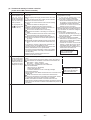
Cautions For REPLACE MULTI Installation Work
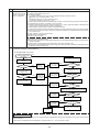
Flow of installation work in the field
Confirming the possibility of existing
refrigerant piping for reuse
Before local installation work
Confirming the possibility of existing
control wiring for reuse
Confirming the possibility of existing
power source system for reuse
Confirming the objective range for
replacing
Recovering the refrigerant of old system
During local installation work
Removing the outdoor/indoor units, remote controllers, etc.
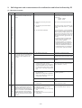
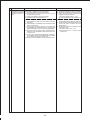
Items to be observed
• Please note that our Corporation is not liable to the reliability of existing piping,
wiring and power system for reuse (in relation with the gas leak of piping, partially
defective/disconnection of wiring, deteriorated insulation, characteristic faults due
to worn out system).
• For limitation on the refrigerant piping and applicable piping diameter, check the
existing piping for reuse in accordance with the specified check sheet by referring to product catalogs and this manuals for judgement to reuse.
• If vapor condensation was found in the past, check the thermal insulation.
• Any portion suffering condensation dripping, check the deterioration of the insulation, and repair the insulation materials if required.
• When the copper piping is seriously deteriorated, do not use parts with verdigris
or black spots.
• For reusing the existing control wiring between the outdoor unit, and remote controller, check the wire type, size or the like, based on the check sheet to judge the
possibility.
• Even when the above does not meet the item on the check sheet, existing wiring
may be reused depending on the number of connecting indoor units and piping
length. Ask us for details.
• For the power source system, employ the voltage and number of phase meeting
the outdoor unit, indoor unit and adopt the breaker capacity and wiring size based
on the power source wiring connection diagram.
• When the existing power source system (including the power source wiring) is
used, check the system for deterioration and damages.
• Check the refrigerating machine oil used in the existing system. (As is found at
the oil inspection), if the refrigerating machine oil used in the existing system is
mineral oil, use the ester oil sampling kit for inspection.
• When the length of piping for reuse is unknown, additional refrigerant charge is
to be calculated based on the quantity of recovered refrigerant. For this reason,
you are kindly requested to recover all refrigerant inside the existing outdoor/
indoor units and extended piping to check and record the quantity. (The standard of additional refrigerant is (Quantity of R22 recovered - Charged quantity of
existing outdoor unit + 3kg). Adjust the refrigerant quantity after mineral oil recovery operation.)
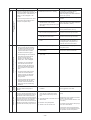
Installing the outdoor/indoor units, remote
controllers, etc., and executing electrical
work
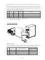
■ Outdoor unit
• Confirm the space around the outdoor unit.
(Verifying the installation space of the oil trap kit)
Setting the address, checking the system
■ Turn the power source on, and confirm the normality of the system
• Check the remote controller or outdoor unit for error display.
• Run the indoor unit for fan operation after turning the remote controller on, and
check the air feeding and direction.
Do not run the compressor until finishing the mineral oil recovery operation.
Executing the piping work (mounting of
ball valve).
Air tightening and evacuating the existing
piping and charging refrigerant
■ Mount the valves to the field piping (extended piping). (The ball valve is attached
to the outdoor unit.)
■ Execute an airtight test to check the existing piping for deterioration or leaking.
■ Calculate the quantity required by the extended piping, and charge the additional refrigerant. Make sure to enter the value in the additional refrigerant charge
column on the label of the outdoor unit.
■ If the refrigerant charge is insufficient, enter the value also.
Without applying any operation, keep the ball valves of the outdoor unit closed
before mineral oil recovery operation.
Enter required items in the request form of REPLACE MULTI mineral oil recovery work.
Operating mineral oil recovery
Executing test run and adjustment (for
final verification of operation).
It is necessary to charge refrigerant in a rated quantity and adjust the quantity.
Be sure to execute when the piping length is unknown.
For detail, consult the agent of your dealer.
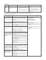
Safety Precautions
• Before installing the unit, make sure you read all the “Safety precautions”.
• The “Safety precautions” provide very important points regarding safety. Make sure you follow
them.
Symbols used in the text
Warning:
Describes precautions that should be observed to prevent danger of injury or death to the user.
Caution:
Describes precautions that should be observed to prevent damage to the unit.
Symbols used in the illustrations
: Indicates an action that must be avoided.
: Indicates that important instructions must be followed.
: Indicates a part which must be grounded.
: Beware of electric shock (This symbol is displayed on the
main unit label.) <Color: Yellow>
Warning:
Carefully read the labels affixed to the main unit.
Warning
Ask your dealer or specialized contractor for
installation.
When refrigerant gas is leaked during work,
conduct ventilation.
• If your own installation work is improper, fire, electric
shock or water leakage may result.
• If refrigerant gas comes into contact with fire, it may
cause the generation of poisonous gases.
Connect wiring using the specified cable and fasten it securely to prevent the external force of
the cable from being transferred to the terminal
connecting sections.
Please conduct correct installation work by
observing this Installation Manual.
• Improper connection or fastening may cause heat
generation or fire.
Conduct specified installation work durable
against strong winds around buildings.
• Improper installation work can cause trouble i.e. the
unit toppling over.
Never attempt to repair the unit. For repair,
ask your dealer.
• Improper repair may result in water leakage, electric
shock or fire.
Do not touch the heat exchanger fins.
• Improper handling may cause cuts.
• Improper installation work may result in water leakage, electric shock or fire.
Conduct all electrical work by a licensed engineer according to “Technical Standard relating to Electrical Facility,” “Wiring Regulation of Power Company,” and instructions in
this Manual, and always use an exclusive circuit.
• Insufficient power source capacity or improper installation may cause electric shock or fire.
When installing or moving the unit, do not
charge other than the specified refrigerant
(R407C) into the refrigeration cycle.
• Air if mixed generates abnormally high pressure inside the refrigeration cycle which may damage the
unit.
Do not reconstruct or reset the protection
devices.
• If the protection devices like the pressure switch or
thermal switch is forcibly operated by short circuiting, or parts other than that specified by Mitsubishi
Electric are used, fire or explosion may be caused.
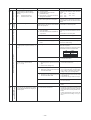
Before Conducting Mineral Oil Recovery Operation
Caution
Turn the power source on 12 hours or more
before starting operation.
Do not turn off the power source immediately
after stopping.
• Otherwise trouble may be caused. Do not turn the
power off during the operating season.
• Be sure to wait for 5 minutes or more. Otherwise
water leakage or troubles may be caused.
Do not operate the unit without the panels or
guard.
Do not touch the refrigerant piping during
operation or immediately after stopping with
bare hands.
• Touching the rotating parts, high temperature parts
or high voltage may cause personal injury such as
burns or electric shock.
Do not operate switches with wet fingers.
• Electric shock may be caused.
• The refrigerant piping or the refrigerant circuit parts
of the compressor during operation or immediately
after stopping may have low or high temperature.
Touching with bare hands may cause a burn or frostbite.
Do not run the outdoor unit during a test run until
finishing the mineral oil recovery operation.
• The indoor unit fan will run.
Caution to Mineral Oil Recovery Operation
Warning
Be sufficiently careful to avoid the oil trap
kit, falling or toppling over.
Be careful not to expose the oil trap kit unit
(especially electrical parts) to rain water.
• If this happens the oil trap kit may be damaged and
refrigerant piping may malfunction.
• Falling down during flushing operation causes the
leak of refrigerant from the joint which is dangerous
if contacts it human body.
• The electrical parts if wet with rain water may cause
machine trouble.
• The electrical parts if wet with rain water may cause
electrical shock.
After flushing operation, check the residual pressure inside the oil trap kit with a pressure gauge.
If the residual pressure is exceeding 0.294MPa,
recover refrigerant inside the oil trap kit to reduce
the pressure to within 0.2 ~ 0.294MPa.
• Under high inner pressure, pressure rises during
storing, inducing a dangerous situation.
• Under low inner pressure, water content or foreign
matter enters during storing, causing corrosion to
the oil trap kit which may cause troubles.
Conduct oil recovery from the oil recovery service valve outdoor or at a place with good ventilation. Use leather gloves when opening the oil recovery service valve and open it slowly.
• If done in a closed space, suffocation can be caused.
• Opening the oil recovery service valve fully and
quickly allows oil to splash, which is dangerous.
• As the oil recovered is of low temperature, frostbite
may be caused if it touches skin.
Caution
When the oil trap kit is transported while lying sideways, do not place any thing on the
sheet metal of the kit.
For inspection, use the ester oil sampling kit
when the refrigerating machine oil used in the
existing unit is mineral oil.
• Otherwise, the sheet metal or inner piping may be
deformed leading to breakage.
(Confirm the type of refrigerating machine oil used in the
existing unit by reading the name plate or the like.)
• Proper checking can not be executed if not using the
kit meeting the refrigerating machine oil used by the
existing unit. This possibly causes machine trouble.
Before removing the oil trap kit after flushing operation, make sure to discharge and
process the oil recovered from the oil recovery service valve.
• If it is not discharged, the oil accumulated inside will
flow out during flushing operation hindering proper
recovery of mineral oil thus leading to machine
trouble.
Precautions for Devices that Use R407C Refrigerant
Caution
Use refrigerant piping made of phosphorus
deoxidized copper and copper alloy seamless pipes and tubes. In addition, be sure
that the inner and outer surfaces of the pipes
are clean and free of hazardous sulphur, oxides, dust/dirt, shaving particles, moisture,
or any other contaminant.
• Contaminants on the inside of the refrigerant piping
may cause the refrigerating machine oil to deteriorate.
Store the piping to be used during installation indoors and keep both ends of the piping sealed until just before brazing. (Store
elbows and other joints in a plastic bag.)
• If dust, dirt, or water enters the refrigerant cycle,
deterioration of the oil and compressor trouble may result.
Use ester oil, ether oil or alkylbenzene (small
amount) as the refrigerating machine oil to
coat flares and flange connections.
• The refrigerating machine oil will degrade if it is mixed
with a large amount of mineral oil.
Use liquid refrigerant to seal the system.
• If gas refrigerant is used to seal the system, the composition of the refrigerant in the cylinder will change
and performance may drop.
Do not use other refrigerant other than R407C.
• Use of other refrigerants (R22 for example) may deteriorate refrigerating machine oil due to chlorine
generation.
Use a vacuum pump with reverse flow protection.
• Otherwise the vacuum pump oil will reversely flow
into the refrigerant circuit causing the possible deterioration of the refrigerating machine.
Do not use the following tools used for conventional refrigerant.
(Gauge manifold, Charging hose, Gas leak
detector, Reverse flow protector, Cap for refrigerant charge, Refrigerant recovery device)
• Mixing of conventional refrigerant /refrigerating machine oil may cause to deteriorate the refrigerating
machine oil.
• Mixing with water may cause deterioration of the refrigerating machine oil.
• As this refrigerant does not contain chloride, the gas
leak detector for conventional refrigerant gas can not
be used.
Do not use a charging cylinder.
• Use of a charging cylinder changes the composition
of refrigerant resulting in possible performance deterioration.
More careful management is required for the
tools than that for the conventional.
• Dust, trash or water content if mixed into the refrigerant circuit may cause to deteriorate the refrigerating machine oil.
Caution to Equipment Used for Replacing
Caution
Do not operate the valve before conducting
mineral oil recovery operation.
Operating valves before conducting mineral oil recovery operation may cause a deterioration in the performance of mineral oil recovery.
For mineral oil recovery operation, the system controller and MA remote controller may
be required to be remove sometimes.
• Improper handling can lead to an inability to perform
oil recovery operation.
• For removal, follow the instruction displayed on the
PC for mineral oil recovery.
• Mount the controllers again after finishing the oil recovery operation.
Observe a safe distance from the indoor unit
fan which runs during the mineral oil recovery operation.
Working in the surrounding of the indoor unit fan can
cause personal injury.
Record the quantity of refrigerant replenished.
(Enter into the column for replenished refrigerant
quantity on the label of the indoor unit.)
• Missing the description may deteriorate the performance of mineral oil recovery.
• Malfunction or poor cooling/heating may also be
caused.
During the mineral oil recovery operation, an
error display may be shown on the remote
controller or system controller.
• When an error display was shown during mineral oil
recovery operation, reset the error display after finishing the operation.
To conduct the refrigerant recovery/evacuation of the inside of exiting piping, choose
tools only used with R407C e.g. charging hose.
• Using a charging hose for R407C causes it to mix
the conventional refrigerating machine oil leading to
the deterioration of refrigerating machine oil.
Before Conducting Installation Work/Electrical Work
Caution
Do not install the unit at a place where combustible gas can possibly be generated.
• Leaked combustible gas if stagnated around the unit
may cause explosion.
Do not use the unit in a special atmosphere.
• Use in an atmosphere containing high levels of oil,
steam or sulfide gas may seriously degrades the performance or damage parts.
Do not install the unit on a material which is
not designed to be wet.
When installing the unit in hospitals or communication equipment plants, prepare measures to prevent noise generation beforehand.
• The noise may cause the erroneous operation or
failure and may give negative effect to medial equipment or communication equipment to disturb medical treatment on human bodies or hinders image
broadcasting or generates noise.
Check possibility for the reuse of existing
refrigerant piping by observing this manual.
• Do not connect the grounding line to gas pipe, city
water pipe, lightning rod or telephone grounding line.
Improper grounding may cause electric shock.
• The conventional refrigerating machine oil is contained inside existing piping and some residual oil
deteriorates oil recovery performance which may
lead to the deterioration of refrigerating machine oil.
• The piping specification (diameter, length , height
difference) out of the use specified range may hinder
the mineral oil recovery performance, possibly leading to deterioration of refrigerating machine oil.
For the power source wiring, refrain from
giving tensile force to the wiring.
Do not use breakers or fuses other than that
with correct capacities.
• Disconnection, heat generation or fire may be
caused.
• Use of a fuse with excessively large capacity or wire/
copper wire may cause troubles or fire.
• If liquid drips from the oil trap kit, apply centralised
drainage work to the oil trap kit.
Apply grounding work securely.
Make sure to mount a leak breaker to the
power source.
• Otherwise electric shock may be caused.
Be sufficiently careful in transporting products.
• Do not transport a product with a weight exceeding
20kg by a single person.
• Some products are packed with PP band. Do not
use it as a means of transporting.
• During transport cuts may be caused by the fin surface of the heat exchanger, please refrain from touching it without gloves.
Do not use the same switch or the like for
plural outdoor units.
Otherwise, malfunction, heat generation or fire may
be caused.
Be sure to mount the valve to the field piping
(extended piping).
After mineral oil recovery, the oil trap kit can not be
removed disabling air conditioning operation.
For the power source wiring, use wire with
rated current capacity.
• Otherwise an electric leak, heat generation or fire
may be caused.
When using existing wiring (for power source
or transmission) or switches, check them for
disconnection and deterioration beforehand.
• Otherwise an electric leak, heat generation or fire
may be caused.
Dispose the packing materials properly.
• As the packing materials are using metal products
or wooden pieces such as nails, nail wounds may
be caused if it is improperly treated. Please observe
caution to avoid this from occuring.
• Dispose the polyethylene bag for packing only after
tearing. Otherwise a suffocation accident may be
caused by children play with the disposed bag.
Provide thermal insulation to the valve on the
field piping (extended piping) properly.
• Insufficient thermal insulation generates condensation that may cause to deteriorate the performance.
• Provide thermal insulation (including lagging) after
recovering mineral oil.
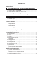
CONTENTS
Caution to REPLACE MULTI Installation Work
Safety Precautions
Simplified Judgment for Reuse of Existing Piping/Wiring
I.
Judgment for Reuse of Existing Piping ..................................................................................... 2
1.
2.
II.
Reusing CITY MULTI air conditioner system .................................................................................. 2
Reusing other makes or Mitsubishi other than CITY MULTI ........................................................... 2
Connection Range of Deformed Piping ..................................................................................... 4
III. Judgment for Reuse of Existing Transmission Line Wiring ................................................. 5
System Design
I.
Outline of Equipment .................................................................................................................... 10
1. Combination of units ...................................................................................................................... 10
2. Temperature range allowing mineral oil recovery operation .......................................................... 10
3. Items to be observed ..................................................................................................................... 10
II.
Product Specification .................................................................................................................... 11
1. Outdoor unit ................................................................................................................................... 11
(1) Specification table
(2) External dimension
2. Oil trap kit ....................................................................................................................................... 13
(1) Specification table
(2) External dimension
III. Outline of Flushing Operation .......................................................................................................... 14
Installation / Operation Work
I.
Parts Provided with Oil Trap Kit ................................................................................................. 17
1. Verifying the parts provided ........................................................................................................... 17
II.
Carrying/Storing the Oil Trap Kit ................................................................................................ 18
1. Transportation by vehicles ............................................................................................................. 18
2. Carrying-in/carrying-out ................................................................................................................. 18
3. Storing ............................................................................................................................................ 18
III. Work Procedure of Mineral Oil Recovery Operation ............................................................ 19
1. Work flow ....................................................................................................................................... 19
2. Items to be checked before work ................................................................................................... 21
3. Installation space and range of oil trap kit ...................................................................................... 23
(1) Restrictions
4. Refrigerant piping work .................................................................................................................. 24
4-1 Piping connection before flushing operation
4-2 Piping connection after flushing operation
5. Electrical wiring work ..................................................................................................................... 30
5-1 Wiring connection before flushing operation
5-2 Wiring connection after flushing operation
6. Connection work on rainy days ...................................................................................................... 31
7. Flushing operation ......................................................................................................................... 32
(1) Installation method of S/W
(2) Items to be confirmed before flushing operation
(3) Starting and finishing of flushing operation
(4) Mounting method of low outdoor temperature hood
IV. Work Procedure at Oil Inspection .............................................................................................. 45
1. Oil inspection after mineral oil recovery ......................................................................................... 45
(1) Oil sampling method
(2) Measuring method and judgement of refractive index
(3) Measures to be taken at oil inspection (No Good)
V. Mineral Oil Recovery Operation Data (Reference Data) ........................................................... 53
1. Standard data (During flushing operation) ..................................................................................... 53
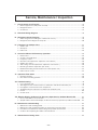
Service, Maintenance / Inspection
I.
Construction of Oil Trap Kit ......................................................................................................... 55
1. External appearance (with panel removed) ................................................................................... 55
2. Refrigerant circuit ........................................................................................................................... 56
3. Control box ..................................................................................................................................... 57
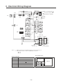
II.
Electrical Wiring Diagram ............................................................................................................ 58
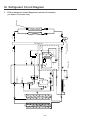
III. Refrigerant Circuit Diagram .............................................................................................. 59
1. Entire refrigerant circuit diagram at mineral oil recovery ................................................................ 59
2. Refrigerant circuit diagram of oil trap kit ........................................................................................ 60
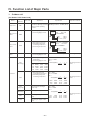
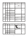
IV. Function List of Major Parts ........................................................................................................ 61
1. Outdoor unit ................................................................................................................................... 61
2. Oil trap kit ....................................................................................................................................... 62
3. Indoor unit ...................................................................................................................................... 63
V. Control of Mineral Oil Recovery Operation ............................................................................. 64
1.
2.
3.
4.
5.
6.
7.
8.
9.
Initial control ................................................................................................................................... 64
Control of solenoid valves .............................................................................................................. 64
Frequency control .......................................................................................................................... 65
Oil return control (Electronic expansion valve <SLEV> ) ............................................................... 66
Outdoor fan control ........................................................................................................................ 66
Sub-cooling coil control (Electronic expansion valve <LEV1>) ...................................................... 66
Detecting circulation composition (CS circuit) ................................................................................ 67
Distributed washing control and flow rate control (Indoor unit) ...................................................... 67
Indoor unit fan control .................................................................................................................... 67
VI. Operation Flow Chart .................................................................................................................... 68
1. Flushing operation ......................................................................................................................... 68
2. Flow chart of flushing operation ..................................................................................................... 69
VII. Troubleshooting ............................................................................................................................. 70
1.
2.
3.
4.
5.
6.
List of checking code ..................................................................................................................... 70
Self-diagnosis and countermeasure for malfunction and failure indicated by PC .......................... 72
Investigation of transmission wave shape/noise ............................................................................ 87
Troubleshooting for major parts of outdoor unit and indoor unit .................................................... 97
Inverter ......................................................................................................................................... 105
Control circuit ................................................................................................................................ 111
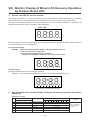
VIII. Monitor Display of Mineral Oil Recovery Operation by Outdoor Board LED .............. 112
1. How to view LED for service monitor ........................................................................................... 112
2. Synoptic table of the monitor display of mineral oil recovery operation by outdoor board LED ... 112
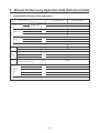
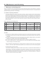
IX. Maintenance and Checking ....................................................................................................... 113
1.
2.
3.
4.
Maintenance and checking period ...............................................................................................
Maintenance and checking procedure for major parts for the oil trap kit .....................................
Procedure for maintenance and checking of the portable refractometer .....................................
Cautions when replacing the outdoor unit main board .................................................................
113
114
118
118
X. Information on Rating Plate ....................................................................................................... 119
Simplified Judgment for Reuse
of Existing Piping/Wiring
I.
Judgment for Reuse of Existing Piping ..................................................................................... 2
1.
2.
II.
Reusing CITY MULTI air conditioner system .................................................................................. 2
Reusing other makes or Mitsubishi other than CITY MULTI ........................................................... 2
Connection Range of Deformed Piping ..................................................................................... 4
III. Judgment for Reuse of Existing Transmission Line Wiring ................................................. 5
-1-
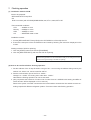
I. Judgment for Reuse of Existing Piping
Both the checking of gas leak inside existing piping and the verification of reliability relating to piping strength
belong to the scope of field work as same as in the past. Therefore, we are not liable to the quality of existing
piping.
Before starting the work, it is necessary to confirm that the existing piping in question owns the rated strength
(relating to the material, thickness, and corroded portions, if any).
Points to be observed for simplified judgment to reuse existing piping
1.
Reusing CITY MULTI air conditioner system
The existing piping can basically be reused if no problem was found during your use in the past.
(Please check whether the trouble was caused by gas leak or it required frequent refrigerant replenishment.)
(1) Change to same capacity → Usable as it is
(2) Change to different capacity → Check whether the piping diameter, piping length, height difference, etc.
are within our operating range.
2.
Reusing other makes or Mitsubishi other than CITY MULTI
(1) Check whether the packaged air conditioner used in the past was in operational trouble or not.
(Please check whether the trouble was caused by gas leak or it required frequent refrigerant replenishment.)
(2) Confirm the type of refrigerating machine oil used by the existing facility.
SUNISO, MS, HAB, Barrel Freeze, Freol are acceptable. For other refrigerating machine oil than the
above, ask our factory in each case.
(3) The branch types of T-fitting, Y-branch and header branching are acceptable.
The branch pipe applied with pressure loss (like the multi-distributor of SLIM) can not be used. Replacement with new branch pipe is required in this case.
Estimate the branch configuration and piping size depending on the maker name, model name and connecting quantity of existing products.
(4) Confirm that the piping diameter, piping length, height difference, etc. are within our operating range.
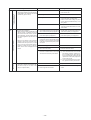
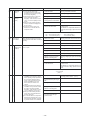
Item, index of judgment for reusing of existing piping
Items
Judgment standard
Indirect material for judgment
Piping diameter, length
Refer to DATA BOOK
None
Type of refrigerating
machine oil
SUNISO, MS, HAB, Barrel Freeze, Freol
Maker, type (model name), year of manufacturing
Air tightness
No pressure drop by leaving for one day after
pressurizing to 2.98Mpa
Operability of previous unit
Distributor configuration
T-fitting, Y-fitting, Header branching
Maker, type (model name), year of manufacturing
Thermal insulation
No peeling off of thermal insulation and caulking
None
Piping system
Unit height difference should be within the standard
of typical unit
None
Pipe thickness
Pipe thickness equivalent to the standard of each
country
-2-
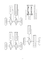
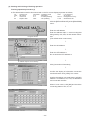
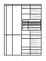
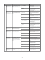
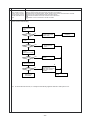
Simplified judgment for reuse of existing piping (Flow)
Do you know the type of refrigerating
machine oil used by the old unit?
YES
NO
Install new piping.
NO
In the piping planned for reuse,
are the outdoor and indoor
units connected?
As the piping left alone
may allow the entry of
dust or the like, refrain
to reuse such piping.
Check it by
asking the maker.
Is it SUNISO, MS, HAB,
Barrel Freeze or Freol?
NO
Start
YES
Is the old unit Mitsubishi?
NO
YES
YES
Can you find the height
difference between outdoor and indoor
units, and between indoor units?
Do you wish to replace with our
Building Multi in the same capacity?
NO
Please check it.
YES
NO
NO
YES
Is the height difference between
indoor and outdoor units less than
50m (40m when outdoor unit locates below
indoor unit), and that between indoor units
less than 15m maximum?
Please investigate.
Do you know the piping
diameter/length?
NO
YES
YES
YES
Do you know the piping
diameter/length?
NO
Please investigate
in the field.
YES
NO
Do the piping diameter and piping
length match our standard?
YES
NO
Do you know the configuration of
the branch piping?
NO
YES
NO
Do you know the maker,
type and model name?
Please investigate
in the field.
YES
Judge the possibility of
reuse by checking the configuration
while referring to the standard.
Is the branch pipe of T, Y
or header branching?
NO
YES
Change the branch pipe
with that specified by us.
YES
Is a gas leak found?
NO
Was the old unit operated before
replacement without refrigerant leak?
YES
NO
Check the air tightness
in the field.
Is the air tightness of
the piping proper?
Is there any branching pipe
not connected with indoor unit?
YES
Can you cut off the
branching pipe?
YES
Provide proper thermal
insulation.
NO
Is the thermal insulation of
piping peeling off ?
NO
NO
Is the rated strength
(material, thickness, corroded portion
if any) kept?
YES
Use new piping.
Existing piping can be used.
-3-
Isolate the branching pipe from
the refrigerant circuit during
mineral oil recovery work.
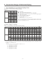
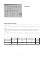
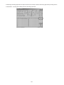
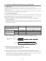
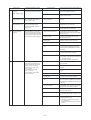
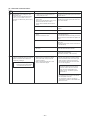
II. Connection Range of Deformed Piping
1.
List of possibility to connect deformed piping (Chart)
(1) Outdoor – First branch [A section (Y series)]
Table-1
P200
P250
x
x
x
x
φ15.88
φ19.05
φ22.2
φ25.4
φ28.58
φ31.75
φ38.1
φ9.52
φ12.7
φ15.88
φ19.05
φ22.2
Gas pipe
Liquid pipe
:
:
● :
:
x
❉
▲
◆
x
❉
x
x
x
x
x
x
x
x
x
x
:
:
:
:
Normal piping
Usable (without performance deterioration)
Usable (with performance deterioration: Refer to DATA BOOK)
Usable (with rule on refrigerant charge: Refer to the formula to judge refrigerant
charge on the next page.)
Usable (with limitation on piping length)
Possible for liquid piping of φ9.52
Not connectable
Limitation on mineral oil recovery work process
This list is presented just for your reference, even the item marked x may be acceptable occasionally depending on the specific field piping condition. Therefore, please
ask the factory individually in such case.
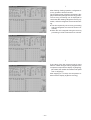
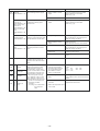
(2) Branch – indoor [a ~ f sections]
Table-2
List of possibility to connect indoor unit/deformed piping
φ12.7
φ15.88
φ19.05
φ22.2
φ25.4
φ28.58
φ31.75
φ38.1
Gas pipe
Liquid pipe
P20
P25
P32
P40
P50
x
x
x
x
x
x
x
x
x
x
x
x
x
x
x
x
x
x
x
x
x
x
x
x
x
x
x
x
x
x
x
x
x
φ6.35
φ9.52
φ12.7
φ15.88
φ19.05
P63
P71
x
P80
x
P100
x
P125
x
P140
x
x
x
x
x
x
x
x
x
x
x
❉
x
x
x
x
❉
x
x
x
x
❉
❉
x
x
x
❉
x
x
x
x
x
x
x
x
x
x
x
x
x
x
x
x
x
x
(within 25m) (within 15m)
x
x
x
x
x
x
x
x
x
x
P200
x
x
x
P250
x
x
x
x
x
Formula to judge refrigerant charge:
For the case marked
, it is necessary to take measures to reduce the piping length slightly, to raise the selecting model or reduce
the number of connected indoor units.
• Y series
M = 0.3 x L1 + 0.2 x L2 + 0.12 x L3 + 0.06 x L4 + 0.024 x L5 < 17.4
L1 : Piping length (m) of φ19.05mm
L2
L3
L4
L5
:
:
:
:
Piping length (m) of φ15.88mm
Piping length (m) of φ12.7mm
Piping length (m) of φ9.52mm
Piping length (m) of φ6.35mm
-4-
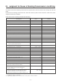
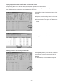
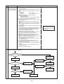
III. Judgment for Reuse of Existing Transmission Line Wiring
To study on the reuse of existing transmission line, please refer to the flow shown later starting from the next
page.
For the reuse of existing transmission line, enter the necessary items into the check list, obtain the system
diagram and contact our dealer.
Check list for reuse of existing transmission line wiring
Checking item
Result
Remarks
1. Remote controller line (MA remote controller)
(1) Length
m
(2) Wire diameter
mm2
(3) Number of wire (number of pole)
Pole
(4) Type of wire (Shielded wire used/not used)
Used / Not used
2. Remote controller line (M-NET remote controller)
(1) Length
❉1
m
(2) Wire diameter
mm2
(3) Number of wire (number of pole)
Pole
(4) Type of wire (Shielded wire used/not used)
Used / Not used
3. Remote controller line (System controller)
(1) Length
❉1
m
mm2
(2) Wire diameter
(3) Number of wire (number of pole)
Pole
(4) Type of wire (Shielded wire used/not used)
Used / Not used
(5) System controller connection
Indoor system/centralized system
Indoor / Centralized
4. Indoor-outdoor transmission line
(1) Refrigerant system
Single/Plural
(2) Transmission line farthest length
Single / Plural
❉1
m
mm2
(3) Wire diameter
(4) Number of wire (Number of pole)
Pole
(5) Type of wire (Shielded wire used/not used)
Used / Not used
(6) Number of connected indoor units
Unit
5. Centralized transmission line
(1) Transmission line farthest length
❉1
m
(2) Wire diameter
mm2
(3) Number of wire (Number of pole)
Pole
(4) Type of wire (Shielded wire used/not used)
Used / Not used
6. Availability of system diagram
(Please try to obtain it much as possible.)
YES / NO
7. Existence of noise trouble on the unit before replacement
(In case of YES, enter the trouble detail into the
column of remarks.)
❉2
YES / NO
8. Is the noise generation from high harmonics medical
equipment estimated? (In case of YES, enter your
apprehensions in detail into the column of remarks.) ❉2
YES / NO
❉1 Include the portion of the remote controller length (M-NET/System controller) exceeding 10m into the figure of the transmissi on line
length (Indoor-outdoor, centralized).
❉2 Regarding the judgment and countermeasure on noise, please contact our dealer.
-5-
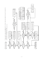
-6-
NO
NO
To transmission
line checking
• Include a portion of wire length exceeding 10m into
the figure of the transmission line farthest length.
❉1
• Make the wire diameter and type as same as that of
transmission line.
YES
Number of wire (pole)
=2?
NO
Arrange the wire not used
as shown in Fig. A.
Arrange MA remote controller
line length below 200m.
Arrange the wire not
used as shown in Fig. A.
Check system controller
remote controller line
To transmission
line checking
YES
Remote controller
line length ≤ 200m?
YES
Number of wire (pole)
=2?
Check MA remote
controller line
NO
NO
A
B
S
Unshielded wire
Shielded wire
A
B
S
For the power supply unit (outdoor unit, power supply device, etc.) side, connect shielded wire to the terminal for
shielded wire, unshielded wire to the terminal for signal,
and open the other ends.
Insulate the opened terminals securely.
Power supply unit
(outdoor unit,
power supply
device, etc.) side
A
B
S
A
B
S
• Include a portion of wire length exceeding 10m
into the figure of the indoor-outdoor transmission line length. ❉1
• Make the wire diameter and type the same as
that of the indoor-outdoor transmission line.
Arrange the wire not
used as shown in Fig. A.
Fig. A Arrangement of wire not used
To transmission
line checking
YES
Remote controller
line length ≤10m?
YES
Number of wire (pole)
=2?
Check M-NET remote
controller line
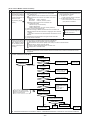
-7-
Possible to reuse existing
transmission line
YES
Indooroutdoor transmission line
farthest length ≤ 120m?
❉1
YES
Single refrigerant
system?
YES
Number of wire (pole)
= 2?
YES
Indooroutdoor transmission
line wire diameter ≥
125mm2 ?
YES
Indooroutdoor transmission line
farthest length ≤ 200m?
❉1
NO
NO
NO
NO
NO
Check transmission line.
NO
NO
NO
Connect the shielded wire to the
outdoor unit (power supply unit)
side for grounding.
YES
Shielded wire?
YES
Centralized
transmission line wire diameter ≥ 1.25mm2 ?
YES
Centralized
transmission line farthest
length ≤ 500m? ❉1
Arrange the wire not used
as shown in Table A.
Confirming the number of indoor
units and the indoor-outdoor transmission line farthest length, read the
usable wire diameter from the graph.
Arrange the indoor-outdoor
transmission line farthest
length less than 200m.
When using other than shielded
wire, be careful for noise. ❉2
Confirming the centralized transmission line farthest length, read
the usable wire diameter from
Table A.
Arrange the centralized
transmission line farthest length
less than 500m.
YES
The diameter of
the wire used is thicker than that read
from the B graph.
Replace the indoor-outdoor
transmission line by that with
a diameter over 1.25mm2.
0.3mm2 or more
130m or less
YES
Replace by the centralized
transmission line with a
diameter over 1.25mm2.
The wire
NO
diameter of the used transmission line is thicker than that usable
in Table A?
0.5mm2 or more
Wire diameter
200m or less
Distance from power supply
unit to outdoor unit and system controller
Table A Usable wire diameter for centralized
system transmission line
NO
❉1 Include a portion of remote controller (M-NET/System controller) wire length exceeding 10m into the figure of the transmission line
(indoor-outdoor / centralized systems) length.
❉2 Ask our dealer for the judgment and countermeasure on noise.
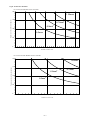
Fig. B Usable wire diameter
For connection with MA remote controller
200
Transmission line farthest length (m)
1.25mm2
150
0.75mm2
0.5mm2
100
0.3mm2
50
0
0
5
10
15
20
30
25
32
Number of indoor unit
For connection with M-NET remote controller
200
Transmission line farthest length (m)
1.25mm2
150
0.75mm2
0.5mm2
100
0.3mm2
50
0
0
5
10
Number of indoor unit
-8-
15
20
System Design
I.
Outline of Equipment .................................................................................................................... 10
1. Combination of units ...................................................................................................................... 10
2. Temperature range allowing mineral oil recovery operation .......................................................... 10
3. Items to be observed ..................................................................................................................... 10
II.
Product Specification ....................................................................................................... 11
1. Outdoor unit ................................................................................................................................... 11
(1) Specification table .................................................................................................................... 11
(2) External dimension ................................................................................................................... 12
2. Oil trap kit ....................................................................................................................................... 13
(1) Specification table .................................................................................................................... 13
(2) External dimension ................................................................................................................... 13
III. Outline of Flushing Operation ........................................................................................... 14
-9-
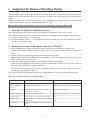
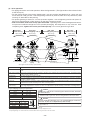
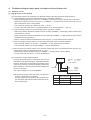
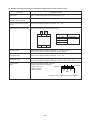
I. Outline of Equipment
1.
Combination of units
The connectable units to this product are shown below.
• Cool/heat selection Y System
Outdoor unit
model name
Total capacity of connected
indoor unit model names
Quantity of connectable
indoor unit
PUHY-P200YREM-A
100 ~ 260
1-set ~ 13-set
PUHY-P250YREM-A
125 ~ 325
1-set ~ 16-set
Connectable indoor unit
model name
P20 ~ P250
New refrigerant series indoor unit
and ventilation relating equipment
Note: The total capacity of connected indoor unit model name represents the summed up total of the numerical figure
portion of the indoor unit model names.
2.
Temperature range allowing mineral oil recovery operation
Outdoor inlet dry bulb temperature
3.
–5 ~ 43˚C
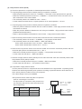
Items to be observed
• Refrigerant flow sound, operating sound of solenoid valve switching
Caution
Countermeasure
During mineral oil recovery, flowing sound may be generated depending on the status of refrigerant. In addition, operating sound may be generated at the switching
of the solenoid valve.
(These symptoms do not represent abnormal states.)
Install the unit at a place not affected by the
sound generated from the unit.
• RE: Effect of noise
Caution
Countermeasure
As the air conditioner uses microcomputer, radiation noise
is emitted from the power source, transmission line and
unit body slightly. If the unit is installed near equipment
that amplify microscopic signals electrically (wireless microphone, medical equipment for example), these equipment may operate erroneously affected by the noise. Further installing the air conditioner near the equipment emitting strong noise (like electric discharge machine etc.)
may cause the malfunction of the air conditioner due to
the noise. In the case when such troubles are expected,
please take the countermeasure shown right.
The equipment which may likely be affected
by noise (receiver of wireless microphone or
antenna) are recommended to be install isolated from the transmission line, power source
line of the unit and the unit body.
The power source line of the equipment emitting strong noise and that of the air conditioner
should be separated, and the transmission
line, power source line and unit body should
be installed isolating each other as much as
possible.
- 10 -
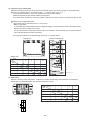
II. Product Specification
1.
Outdoor unit
(1) Specification table
Y Series
Outdoor unit model name
PUHY-P200YREM-A
Power source
3N~ 380/400/415V 50/60Hz
❉1
Cooling capacity
kW
22.4
28.0
kW
25.0
31.5
Cooling
kW
6.32
8.54
Heating
kW
6.80
8.95
Cooling
A
10.6/10.1/9.7
14.4/13.6/13.2
Heating
A
11.4/10.9/10.5
15.1/14.3/13.8
Electrical
characteristic
Heating capacity
Power
input
Current
Refrigerant/Lubricant
R407C/MEL32
Type x quantity
Compressor
Hermetic x 1
Motor output
5.3
kW
Starting system
W
45 (240V)
Type x Quantity
Airflow rate
3
m /min
200
200
kW
0.38
0.38
High pressure protection
2.94MPa
Compressor
Over current protection • over heat protection
Fan
Thermal switch
Inverter
Refrigerant
piping diameter
Over current protection • thermal protection
Gas pipe
mm
φ25.4
φ28.58
Liquid pipe
mm
φ12.7
φ12.7
dB(A)
56
57
❉2
Noise level
External finish
External
dimension
45 (240V)
Propeller fan x 1
Motor output
Protection
devices
6.8
Inverter start
Crankcase heater
Fan
PUHY-P250YREM-A
Pre-coated galvanized sheets (MUNSELL 5Y 8/1 or similar)
High
mm
1755
1755
Width
mm
990
990
Depth
mm
840
840
kg
239
239
Net weight
Operating temperature range
Indoor : 15˚CWB~24˚CWB
Outdoor : –5˚CDB~43˚CDB
(0˚CDB~43˚CDB with outdoor unit at lower position)
Matters deserving special mention
A pipe of φ28.58 can be used for the gas pipe
Indoor : 15˚CDB~27˚CDB
Outdoor : –15˚CWB~15.5˚CWB
Note : 1. Cooling/heating capacity indicates the maximum value at operation under the following condition.
❉1 Cooling Indoor : 27˚CDB/19˚CWB
Outdoor : 35˚CDB
Heating Indoor : 20˚CDB
Outdoor 7˚CDB/6˚CWB
Piping length : 7.5m
❉2 It is measured in anechoic room.
- 11 -
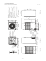
Cross section Y-Y
Rear view
100
251
778
75
80
Knockout hole
Left piping hole
Left side view
φ27 Knockout hole
<Left side hole for the
control wiring>
60
Cross section X-X
160
Y
Refrig. service
valve (liquid)
φ12.7<flare>
40
Refrig. service
valve(gas)
<flange>
φ40 Knockout hole
<Left side hole for
the power supply>
75
X
Knockout hole
31
79
Oval hole
2✕2-14✕20
φ27 Knockout hole
<Bottom side hole for
the control wiring>
φ40 Knockout hole
<Bottom side hole for
the power supply>
165
80
215
Front view
590
Knockout hole
Front piping hole
<Front wiring hole>
813
Plane view
990
560(bolt hole)
55
(215)
910
X
Service panel
1490
Knockout hole
<Front side hole for
the power supply>
Air
inlet
Right side view
Air outlet
Air
inlet
Note:
1. Please leave a space under the outdoor unit for
the piping. When you connect the piping from
the bottom.
(Please be careful not to close the hole of the
bottom plate by the basement.)
<Accessories>
• Refrigerant <gas> connecting pipe ............. 1 pc.
(The connecting pipe is fixed with the unit)
• Packing for connecting pipe ........................ 1 pc.
(Attached near ball valve)
• Wiring mounting board ................................ 1 pc.
• Conduit mounting plate
(Painting the same color as the unit body)
φ40, φ33, φ27 .................................... Each 1 pc.
• Tapping screw 4 x 10 ................................. 6 pcs
• Parts of mineral oil recovery ....................... 1 set
Models PUHY-P200, P250YREM-A
Knockout hole
Conn. pipe
200: φ25.4 <brazed>
250: φ28.58<brazed>
315: φ31.75<brazed>
25
Note1
Knockout hole
Bottom piping hole
<Bottom wiring hole>
237
198
50
234
73 80
Y
194
(15)
880(bolt hole)
15
5
149
121
100
48
40
70
840
78
- 12 99
12
1755
(2)
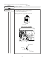
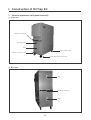
External dimensions
Unit: mm
2.
Oil trap kit
(1)
Specification table
Oil trap kit model name
Power source
Power consumption
Electrical
characteristic
Current
External finish
Height
External dimension
Width
Depth
Ball valve side
(at outdoor unit)
Refrigerant piping
Fitting side
(at extended piping)
kW
A
mm
mm
mm
mm
mm
mm
mm
kg
High pressure
Low pressure
High pressure
Low pressure
Net weight
Accessories
PAC-KP90VCLU
~N 220/230/240V 50Hz
0.049
0.20/0.21/0.22
Galvanized steel sheets
1091
336
757
φ12.7 Flare connection
φ28.58 Flange connection
φ15.88 Flare connection
φ19.05 Flare connection
76
Packing ❉1, Hood for low OA ❉2
Pipe 1,Pipe 2, Saddle, Packing, Screw
❉1 The packing is provided for 5 pcs. (mineral oil recovery for 1 time). Please purchase additional packing if required.
(Service parts code : R61 F14 514, Service model name code : P321009X01)
❉2 Service parts code : R61 M03 622, Service model name code : W650296G01
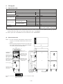
(2)
External dimension
Notes: 1. For the connection and operation control of the oil
trap kit, you are kindly requested to obtain our approval.
2. Make the piping length between the oil trap kit and
the outdoor unit 5m or less. <The optional flexible
hose (2m) is prepared by Mitsubishi.>
845
336
75
77
Power source
terminal block cover
Terminal for PC
connection
<RS-232C>
Piping
cover
999
Refrigerant service
valve <outdoor unit
low pressure side>
φ19.05 <flare>
Refrigerant service
valve <outdoor unit
high pressure side>
φ15.88 <flare>
65
Refrigerant service
valve <outdoor unit
low pressure side>
φ28.58 <flange>
Refrigerant service
valve <outdoor unit
high pressure side>
φ12.7 <flare>
757
A
90 50
1091
77
Handle
787
Pressure gauge
559
Valve
cover
272
130
92
Refrigerant service
valve <oil recovery>
φ6.35 <flare>
Caster <swivel side>
with stopper
N L
M1 M2 S
Transmission terminal block
(TB02)
Power source terminal block (TB01)
Details of A-section
- 13 -
Caster
<stopper side>
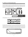
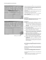
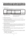
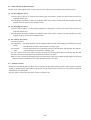
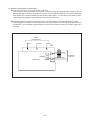
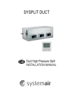
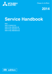
III. Outline of Flushing Operation
Install the oil trap kit between the outdoor unit and extended piping. Operation of the outdoor unit is in cooling
mode, feeding the R407C charged in the system under a gas/liquid two-phase state from the oil trap kit heat
exchanger. By feeding the refrigerant in the gas/liquid two-phase state into the existing piping, the residual
mineral oil inside the existing extended piping can be recovered into the oil trap kit. Feeding oil fluidity solution
from upstream of the existing piping can maintain or even increase the fluidity of residual mineral oil, thus
allowing the mineral oil to flow through the indoor units.
Outdoor unit
Separates and recovers oil
with fluidity solution.
Oil trap kit
❉
4-way valve
Outdoor
heat exchanger
Throttle
Oil
separator
Outdoor unit
Oil trap
Indoor heat
exchanger
Oil
separator
Refrigerant heat
exchanger
Accumulator
Indoor unit
throttle
Mineral oil
fluidity solution
Replace tank
Promotes flushing by lowing the
viscosity of the oil.
Flow of ester
Flow of mineral oil
Flow of refrigerant (hot gas)
Flow of refrigerant (low pressure gas)
Flow of refrigerant (gas/liquid 2-phase refrigerant)
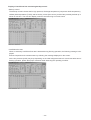
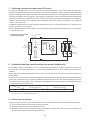
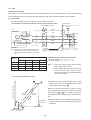
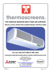
Principle of recovery by refrigerant under gas/liquid 2-phase state incompatible with mineral oil
(❉ mark portion above)
Piping center
Refrigerant gas
(R407C)
Floating layer of
mineral oil
Mineral oil attached
to wall surface
Refrigerant liquid
(R407C)
Pipe wall of refrigerant piping
The mineral oil used as the refrigerating machine oil of conventional refrigerant (R22) systems are oils mostly
incompatible with new refrigerant (R407C). By flowing R407C to piping attached with mineral oil, the mineral oil
is forced out and peeled off from the pipe wall by the shearing force applied between the mineral oil and
refrigerant liquid. Then it is carried out while floating on the surface of refrigerant liquid. If it is under gas/liquid
2-phase state at this moment, the liquid refrigerant will be accelerated by gas refrigerant flowing at high speed
in the center of the pipe. Thanks to this accelerated flow, the mineral oil inside piping can be collected quickly.
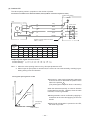
Residual quantity
Longest extended piping : 100m
Maximum extended length : 220m
(Liquid/gas going and returning for 440m)
0
20
40
60
Flushing time (min)
80
100
Residual oil quantity in piping against flushing time
- 14 -
120
Installation / Operation Work
I.
Parts Provided with Oil Trap Kit ................................................................................................. 17
1. Verifying the parts provided ........................................................................................................... 17
II.
Carrying/Storing the Oil Trap Kit ................................................................................................ 18
1. Transportation by vehicles ............................................................................................................. 18
2. Carrying-in/carrying-out .................................................................................................................. 18
3. Storing ............................................................................................................................................ 18
III. Work Procedure of Mineral Oil Recovery Operation ............................................................ 19
1. Work flow ....................................................................................................................................... 19
2. Items to be checked before work ................................................................................................... 21
3. Installation space and range of oil trap kit ...................................................................................... 23
(1) Restrictions
4. Refrigerant piping work .................................................................................................................. 24
4-1 Piping connection before flushing operation
4-2 Piping connection after flushing operation
5. Electrical wiring work ..................................................................................................................... 30
5-1 Wiring connection before flushing operation
5-2 Wiring connection after flushing operation
6. Connection work on rainy days ...................................................................................................... 31
7. Flushing operation ......................................................................................................................... 32
(1) Installation method of S/W
(2) Items to be confirmed before flushing operation
(3) Starting and finishing of flushing operation
(4) Mounting method of low outdoor temperature hood
IV. Work Procedure at Oil Inspection .............................................................................................. 45
1. Oil inspection after mineral oil recovery ......................................................................................... 45
(1) Oil sampling method
(2) Measuring method and judgment of refractive index
(3) Measures to be taken at oil inspection (Failure to pass oil inspection test) (No Good)
V. Mineral Oil Recovery Operation Data (Reference Data) ........................................................... 53
1. Standard data (During flushing operation) ..................................................................................... 53
- 15 -
- 16 -
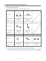
I. Parts Provided with Oil Trap Kit
1.
Verifying the parts provided
Please confirm that the following parts are provided with this oil trap kit.
Name
(1) Hood (for low OA)
(2) Packing
Appearance
Inner diameter
φ23
Storing position
Quantity
Name
Outer diameter
φ35
Provided at the control
box bottom
Provided at the control
box bottom
1 pc.
5 pcs.
(3) Piping 1
(4) Piping 2
Provided inside
piping cover
Provided inside
piping cover
1pc.
1pc.
(5) Rubber mount
(6) Saddle
(7) Screw
Provided at the control
box bottom
Provided at the control
box bottom
Provided at the control
box bottom
1pc.
1pc.
4pcs.
Appearance
Storing position
Quantity
Name
Appearance
Storing position
Quantity
(1)
(2)
Service parts code : R61 M03 622, Service model name code : W650296G01
The packing is provided for 5 pcs. (mineral oil recovery for 1 time). Please purchase additional
packing if required. (Service parts code : R61 F14 514, Service model name code : P321009X01)
- 17 -
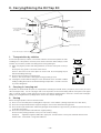
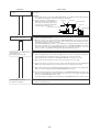
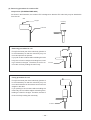
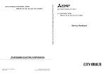
II. Carrying/Storing the Oil Trap Kit
Piping cover
Knob
Knob
Name plate
❉Unscrewing the screws
(at 4 spots) allows using
the handle.
For the unit with a handle instead
of knobs, the handle can be dismantled by removing the upper/
lower panels and M8 bolts (2 pcs.)
fixing the handle. Do not operate
the unit with the upper/lower panels removed.
Handle
Knob
Knob
Caster (stopper side)
Caster with stopper (swivel side)
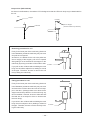
1.
Transportation by vehicles
For the transportation by vehicles, ensure that sufficient care has been paid to the withstanding force of the product. However, please observe the items below and pay careful
attention to prevent the product from falling down or being damaged.
(1) When carrying the product while being laid down, locate the name plate on the upside.
Do not place any goods on the sheet metal surface.
Reason : The letters on the name plate can not be read. The inner piping may be
deformed leading to damage.
(2) Do not locate the piping cover downward.
Reason : The service valve is damaged causing possible gas leak.
(3) Carrying the product while locating the caster downward causes unstable condition
leading to falling down due to the vibration during transportation. Provide a measure
to prevent falling down.
2.
Surface with
name plate
Fixing material
Carrying-in / carrying-out
The product is mounted with the parts for transportation, including one handle, knobs (at 5 places) and casters (at swivel
side and stopper side). For the carrying-in and -out of the product, locate it horizontally (with the name plate at the upper
side) or vertically and pay careful attention to prevent it from falling or dropping due to obstacles. Refrain from locating the
piping cover facing downward. (If dropped, the service valve may be damaged.)
3.
Storing
When storing the product, observe the items below.
(1) Store in a cool and dark place avoiding direct exposure to solar radiation. (Storing temperature less than 60˚C)
(2) Store the oil trap kit fixed with the stopper locating the caster in the downward facing position.
(3) Store the oil trap kit, flexible tube and branch piping kit mounted with the cap previously provided. (to prevent the entry
of dirt, dust and water)
(4) Store the oil trap kit, flexible tube with their original packing.
Do not lose the packing materials as they are to be used for storing.
Oil trap kit : Applied corrugated cardboard to upper part, wooden frames to lower part and fixed with PP band.
Flexible tube : Packed with corrugated cardboard
- 18 -
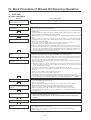
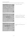
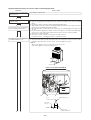
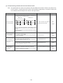
III. Work Procedure of Mineral Oil Recovery Operation
1.
Work flow
For P200 • P250YREM-A
Work flow
Items to be verified
Carry in the oil trap kit (1 set),
replace tank, PC and tools.
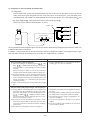
Check the necessary parts (P20) & check the work preparation (P21).
Install the oil trap kit, replace
tank and PC.
1. Turn the outdoor unit power source off.
2. Mount the replace tank to the oil trap kit..
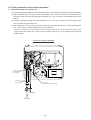
3. Connect the outdoor unit, valve mounted to the extended piping and oil trap kit with piping
(flexible tube).
4. Conduct airtight test and evacuation the piping (flexible tube) between the outdoor unit,
valve mounted to the extended piping and oil trap kit.
5. Open the ball valve. (in the order of oil trap kit (1)~(4), extended piping, outdoor unit (1) and
(4).)
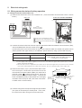
6. For the oil trap kit, apply from L1 and N of outdoor unit supply or a separate 220~240V
supply power source of the outdoor unit and the transmission line from the outdoor unit TB3.
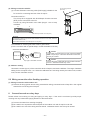
7. Connect the oil trap kit and PC.
8. The system controller and MA remote controller may be required to be remove.
For detail, refer to 1~5 : Piping connection, 6 •7 Piping connection.
❉ When conducting mineral recovery work the next day, close all service valves of the outdoor unit, valve mounted to the extended piping and oil trap kit to finish the work, and open
all service valves immediately before starting flushing operation. (Otherwise mineral recovery time is extended due to prolonged start-up time, or the oil traped inside the kit is overflown hindering the normal mineral oil recovery.)
Perform air tightness test
Evacuate the piping (Flexible tube)
Apply flushing inside of the exiting
piping.
Recover mineral oil inside the
oil trap kit.
Remove the oil trap kit.
Connect the piping kit processed
there, and evacuate inside of the
piping kit.
1. Apply power source to the outdoor unit, and confirm the completion of the start-up.
2. Check the operating sound caused by the ON/OFF of the solenoid valves.
3. Through the PC operation, drive the outdoor unit compressor to recover mineral oil inside the
extended piping. The recovery time requires for 1.5 ~ 3 hours. (Outdoor temperature below
20˚C, the low outdoor air hood should be fitted to the outdoor unit.)
However under low outdoor temperature, flushing operation may be required again due to
insufficient refrigerant.
❉ When the frequency or low pressure drops less than the rated value due to insufficient
refrigerant and the such like, the time required for the mineral oil recovery may exceed 3
hours. For detail, refer to P36.
4. Prevent the outdoor unit and oil trap kit from being exposed to rain directly.
5. Close the service valves of the outdoor unit and the valve mounted to the extended piping (4
positions).
6. Close the service valves of the oil trap kit (at 4 spots).
7. Turn off the power source of the outdoor unit once.
8. After flushing operation, recover mineral oil by opening the oil recovery service valve.
❉ The mineral oil recovered by flushing operation should be extracted each time from the oil
trap kit. During the work, observe that the pressure is staying within 0.049 ~ 0.294MPa.
1. Remove piping (flexible tube) and wiring between the outdoor unit, remove valves mounted
to the extended piping and oil trap kit.
2. Remove the oil trap kit.
3. After reconnecting the piping kit (field work) to the outdoor unit, execute evacuation.
4. Open the ball valve (in the order of extended piping, outdoor unit (1) and (4).)
5. Mount the system controllers and MA remote controller previously removed.
❉ After removing the oil trap kit, confirm the inner pressure with a pressure gauge.
❉ Do not store the oil trap kit at a place exposed directly to solar radiation, but store in a cool
and dark place.
Confirm operation
(compressor starting).
After recovering oil, conduct ordinary air conditioning operation, and check the cooled air (heated
air) and the operating condition of the compressor.
❉ The test run and adjustment work are not included. Execute them separately if
required.
Execute test run & adjustment.
This belongs to the field work category. Execute it after flushing.
Inspect oil one month after
operation.
1. For the inspection of oil, use suitable kit for the refrigerating machine oil used by the existing
unit. (Mineral oil : Ester collection kit)
2. When the recovery of mineral oil is insufficient, ester oil, etc. should be added.
❉ Note: Only in rare cases.
- 19 -
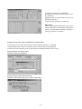
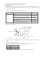
Mineral Oil Recovery Operation
Parts List
Parts name
Application
Specification (quantity)
Remarks
(1)
Oil trap kit
(PAC-KP90VCLU)
Mineral oil recovery
device
Built-in solenoid valve, pressure sensor,
pressure gauge, service valve
1 set
(2)
Flexible tube
(PAC-KP80FPP,
PAC-KP-82FPP,
PAC-KP83FPP)
Piping connection between
oil trap kit and outdoor unit
and the valve mounted to the
extended piping
φ12.7 (2 pcs.), each 1 pc. of φ19.05 and φ28.58
(φ19.05 is for short copper pipe [requires φ28.58
–φ19.05 connection])
1 set
(3)
Packing
Connection between (2) flange 5 pcs. (outdoor unit 2 pcs. valve mounted to the exand outdoor unit
tended piping 2 pcs., oil trap kit 1 pc.)
[provided inside oil trap kit]
(4)
PC (Field supply)
Mineral oil recovery
operation control
Equipment:
DOS-V machine (suitable for PC-98NX or later)
CD ROM equipped
CPU
: 300MHz or larger (recommended)
Memory : 64Mbyte or larger (recommended)
HDD
: 40Mbyte or larger (recommended)
O/S
: Windows95, 98, NT 4.0, 2000, ME, XP
(5)
Software
Mineral oil recovery
operation software
Exclusive S/W for Replace
(Caution : Install on PC before mineral oil recovery.)
(6)
Connecting cable
(field supply)
RS-232C connection of
oil trap kit and PC
RS-232C cross cable (within 15m)
Oil trap kit connector specification : D-SUB25 Pin type
female connector (DTE)
(Caution: Select RS-232 cable depending on the type
of the serial interface of PC.)
(7)
Power source wiring
(field supply)
Connection to oil trap kit
(Jumper from outdoor unit)
φ1.5mm2 or more
Power supply cord parts of appliances for heat source
shall not be lighter than polychloroprene sheathed
flexible cord (design 245IEC57)
(8)
Control wiring
(field supply)
(9)
Oil pan (field supply)
(10)
Refrigerant piping,
Verification of connection with Refrigerant piping/wiring system diagrams are
Wiring system diagram system controller, others
required for each system
(11)
Ester oil check kit
(PAC-KP95ECK)
(Use when the refrigerating machine oil used
by conventional system
is the mineral oil.)
Vessel (1 pc.), bottles (2 pcs. 1 pc. with oil charged)
To judge proper oil recovery
at oil inspection about one
month after flushing operation
executed
(12)
Replace tank
(PAC-KP01RTK)
To lower the viscosity of
residual mineral oil
φ1.25mm2 or more
2-core cable (VCTF, VCTEK, CVV, CVS, VVR, VVF,
VCT or shielded wire CVVS/CPEVS)
Mineral oil recovery vessel
Vessel with more than 2L capacity is required.
Mineral oil fluidity solution
- 20 -
1 set for
1 outdoor unit
2.
Items to be checked before work
Check method
(1)
Confirming the power- 1) LED display inside
1) Check whether outdoor unit is being of outdoor unit
outdoor unit control box
ing powered.
2) Confirming the powering time
(2)
Content of checking
1) Power the outdoor unit for over 12
hours.
2) Check the insulation resistance
between power source terminal
and ground for over 1.0MΩ.
2) Power until the insulation resistance
between the power source terminal block and ground reaches
1.0MΩ or more.
Confirming the closed 1) Confirming the closed
1) Confirm the ball valve of outdoor
ball valve of outdoor
ball valve of outdoor
unit is fully closed.
unit and the valve
unit, oil trap kit, and
the valve mounted to
mounted to the extend- 2) Confirm the ball valve of oil trap
ed piping
the extended piping
kit is fully closed.
1) Full opening of ball valve
• Check the valve operation by field
piping work.
• Refrigerant charge after flushing
operation.
2) Confirming the closed
ball valve of oil trap kit
(3)
Countermeasure
1) Confirming by observConfirming the coning refrigerant system
nection of the system
diagram
controller to transmission terminal block
Confirming MA remote 2) Confirming the field
controller
connection
2) Full closing of ball valve
• Confirmation of residual pressure
inside oil trap kit (by using a pressure gauge) →At no residual pressure, evacuate after confirming
airtightness inside oil trap kit and
charge refrigerant by 0.5kg.
1) Check whether system controller
is connected to indoor/outdoor
transmission line.
2) The system controller that turns
the power source off when turning
the outdoor unit power source off
is connected to the indoor system.
(Power supply from outdoor unit)
3) Check MA remote controller for
grouping with different refrigerant
circuits.
1) 2) 3) Remove the system controller connected to the indoor/outdoor
transmission line and MA remote
controller grouped with different refrigerants. Reconnect them after
flushing operation. (Only required
when indoor unit under Ver30 or
LOSSNAY with heating humidifier
under Ver8.08 is existing. : Removal is indicated on the PC
screen. )
(4)
Confirming the inner
1) Confirming with prespressure of oil trap kit
sure gauge
1) Check whether the reading of
pressure gauge inside oil trap kit
is lower than 0.049 ~ 0.294MPa.
Refer to the countermeasure by confirming the oil trap kit inner pressure
shown on the next page.
(5)
Confirming the oil
recovery of oil trap kit
1) Open the oil recovery service
valve and check whether the liquid (recovered oil) flows out continually under liquid state.
1) Recover liquid (recovered oil) with
an oil pan and the like.
1) Confirming the operation of oil recovery
service valve
- 21 -
Countermeasure by Confirming Inner Pressure of Oil Trap Kit
(1) In the case of 0.049MPa or less
A leak exists, it must be located and repaired. After repairing the leakage inside the oil trap kit, confirm
successful airtightness test and evacuation. After evacuation, charge refrigerant 0.5kg.
(2) In the case of 0.294MPa or more
Confirm the outdoor temperature sensor (TH6) of the outdoor unit.
Reference to chart below.
1) Located at lower right side of line
Although this does not indicate abnormality, but causes increase in the inner pressure during storage
leading to possible danger. Recover refrigerant to lower the pressure until it reaches less than 0.294MPa.
For the method of refrigerant recovery, refer to [IX. 2. 2-3 Refrigerant recovery method].
2) Located at upper left side of line
This indicates the existence of liquid refrigerant. Liquid seal may be formed at storage. Recover refrigerant to lower the pressure until it reaches less than 0.294MPa same as above. For the method of
refrigerant recovery, refer to [IX. 2. 2-3 Refrigerant recovery method]. At recovery, measure the recovered quantity. If it exceeds 0.5kg, charge the excess quantity additionally when confirming operation.
In addition, check the operation of the solenoid valves. If they are faulty, replace the solenoid valves,
confirm airtightness and execute evacuation. After evacuation, charge refrigerant 0.5kg.
Saturated pressure against outdoor inlet dry bulb temperature (Gas)
1.6
1.5
1.4
1.3
Abnormal (Possibility of liquid sealing)
Pressure (MPa)
1.2
1.1
1
0.9
0.8
0.7
0.6
Normal
0.5
0.4
0.3
0.2
0.1
0
-5
0
5
10
15
20
25
30
Outdoor inlet dry bulb temperature TH6 (˚C)
- 22 -
35
40
3.
Installation space and range of oil trap kit
The installation space required for the oil trap kit and for the piping network is as follows. The installation can
be performed by using the front service space of the outdoor unit.
In the case when the installation space of the oil trap kit can not be secured (due to obstacles), install it within
the following restrictions on piping length. Arrange the installation so that the unit front is not exposed to
seasonal winds (gusts).
(1) Restrictions
Item
Allowable length
Piping length
Remarks
5m or less
Height difference
Outdoor unit upper
5m or less
Outdoor unit lower
5m or less
The piping length added with piping length
and height difference should be less than 5m.
In the case of P200 • 250YREM-A
Outdoor unit
Over 450
Oil trap kit
Over 990
Caution
When installing the oil trap kit on a slanted ground or at a place directly
exposed to the seasonal wind (gust), ensure it will not be blown over.
• If the oil trap kit does fall over it will damage the solenoid valves disabling the ability to
perform flushing operation. Refrigerant leak and personal injury may also occur.
- 23 -
4.
Refrigerant piping work
4-1 Piping connection before flushing operation
(1) Piping connection to outdoor unit
Connect the outdoor unit and oil trap kit, pipe and wire by following the procedure.
(1) Turn off the main power source of the outdoor unit.
(2) Remove the service panel from the outdoor unit and oil trap kit, piping cover and the side panel (6
screws in total).
(3) Confirming the service valves of the outdoor unit, valves mounted to the extended piping and oil trap kit
are closed, and remove a piping cover. Mount the replace tank to the oil trap kit. (Use the Piping 1 and
2 provided to the oil trap kit to mount the replace tank.)
❉ Do not lose the Piping 1 and 2 of the oil trap kit, as it can be reused. When using the copper pipe for
general refrigerant piping, connection can be performed without using Piping 2 by using the valve of
the replace tank.
In the case of P200 • 250YREM-A
Left side panel
(upper)
Piping 1
(Accessory)
Replace tank
Valve cover
Service panel
Piping 2
(Accessory)
In the case of P200 • 250YREM-A
Service valve
(low pressure)
Service valve
Service valve
(high pressure)
- 24 -
(4) Connect the flexible tube to the outdoor unit, valve mounted to the extended piping and oil trap kit (1) ~
(4).
When general refrigerant piping copper pipe is used, select a suitable type by referring to the piping
specification of flexible tube shown below. When the length of piping connected to the outdoor unit and
oil trap kit exceeds 2m, use the general refrigerant piping copper pipe with the selected diameter for a
portion of over 2m by referring to the following table.
Piping dia.
(mm)
Pipe thickness
Piping length
(mm)
Remarks
(1)
φ12.7
0.9
2m
(2)
φ12.7
0.9
2m
(3)
φ19.05
1.0
2m
Requires to mount short copper pipe (φ28.58–φ19.05)
(4)
φ28.58
1.2
2m
Requires to mount flange ❉1
Caution : Mount the connecting pipe (1) ~ (4) correctly without erroneous connection.
Erroneous connection does not allow recovery of mineral oil.
❉1 Service parts code
R61 E91 494
In the case of P200 • 250YREM-A
(1) PAC-KP80FPP
(1)
(3)
(3) PAC-KP82FPP
(4)
(4) PAC-KP83FPP
(1)
(2) PAC-KP80FPP
(2)
(4)
(3)
(2)
Field piping
Connection method:
Remove short copper pipe and flare nut, select the flexible piping corresponding to the number in the
drawing shown above from the following table, and connect to the port with same number.
No.
Type
Connection configuration
Quantity
P200, 250YREM-A
(1)
PAC-KP80FPP
φ12.7 flare conn. – φ12.7 flare conn.
1
(2)
PAC-KP80FPP
φ12.7 flare conn. – φ12.7 flare conn.
1
(3)
PAC-KP82FPP
Flange joint – φ19.05 flare conn.
1
(4)
PAC-KP83FPP
Flange joint – Flange joint
1
- 25 -
(2) Valve operation
• For piping connection and valve operation, follow the figure below. (The figure below shows the ball valve
of the oil trap kit.)
• For the flange section of the piping (flexible tube), use new packing (provided only for 1 time use) and
mount firmly to avoid gas leak. Coat refrigerating machine oil (ester oil, ether oil or alkyl benzene (a little
amount)) on both sides of the packing.
• For opening/closing of flare nuts, use two spanners together. Coat refrigerating machine oil (ester oil,
ether oil or alkyl benzene (a little amount)) on the flare contacting surface.
• After evacuation, make sure to fully open the handle. Operating with a valve closed generates abnormal pressure inside the refrigerant circuit, possibly damaging the compressor, 4-way valve etc. After
completing work, tighten the service port and cap firmly, so as not to generate a gas leak.
Ball valve
Outdoor unit (1)
Ball valve
Extended piping side (2)
Ball valve
Extended piping side (3)
Open (slowly)
Open (slowly)
Open (slowly)
Ball valve
Outdoor unit (4)
Open (slowly)
Valve rod
O
O
S
O
S
O
S
S
Cap, Copper packing
Packing
(Accessory)
φ 15.88
φ12.7
To outdoor unit
φ19.05
Stopper pin
Service To extended
port
piping
φ28.58
Service port
Flare nut To extended piping
Connection pipe (Accessory)
(This figure shows the fully opened state.)
Part name
Valve rod
To outdoor unit
Detail
Fully close at shipment, piping work, air tightening and evacuating work. Fully open after completing the above
works.
Cap, Copper packing Remove the cap and operate the rod valve. Mount it at its original position after finishing work. (Clamping torque
of valve rod cap : 25N•m or more)
Stopper pin
The valve rod does not rotate over 90˚.
Service port
Use for the airtightness and evacuation inside existing piping in the field. Use two spanners to open/close. (Clamping torque : 14N•m or more)
Flare nut
Use two spanners to open/close with a clamping torque of 80N•m. Coat refrigerating machine oil (ester oil, ether oil
or alkyl benzene (a little amount)) on the flare contacting surface.
Connection pipe
(Accessory)
Mount the packing (accessory) firmly to the valve flange to avoid gas leak. (Clamping torque : 23N•m or more)
Coat refrigerating machine oil (ester oil, ether oil or alkyl benzene (a little amount)) on the flare contacting surface.
Proper clamping torque by torque wrench
Copper pipe OD (mm)
φ6.35
φ9.52
φ12.7
φ15.88
φ19.05
Clamping torque (N•m)
14 ~ 18
35 ~ 42
50 ~ 57.5
75 ~ 80
100 ~ 140
Standard of clamping angle
Pipe dia.
φ6.35 φ9.52
φ12.7 φ15.88
φ19.05
Clamping angle
60˚ ~ 90˚
30˚ ~ 60˚
20˚ ~ 35˚
Caution
Make sure to remove the connection pipe from the ball valve, and braze
it outside the unit.
• Brazing it while mounted heats the ball valve which may cause
machine trouble or gas leak. Also the wiring inside the unit may be burnt.
Caution
For the refrigerating machine oil to coat on the flare/flange connections,
use ester oil, ether oil or alkylbenzene (a little amount).
• Mixing of mineral oil in a large quantity may cause a deterioration of refrigerating machine oil.
❉ When a torque wrench is not available, use the method below instead.
When tightening the flare nut with a spanner, the clamping torque may abruptly increases.
Stop the tightening once at this moment, and rotate further for the angle shown in the above table.
- 26 -
(3) Airtightness and evacuation of flexible tube
(1) Airtight test
For the airtight test, pressurize the flexible tube from the service port on the end of it (at the oil trap kit
side) while closing the refrigerant service valve (ball valve) of the oil trap kit, valve mounted to the
extended piping and outdoor unit while opening the valve of the replace tank. After applying to 1 and
3 , apply to 2 and 4 . (The figure below shows the state of 1 and 3 .)
Make sure to pressurize all flexible tubes. (4 spots)
Replace tank
1
2
3
System analyzer
LO
Nitrogen
gas
Oil
trap
kit
HI
Lo knob
4
Hi knob
As the procedure of the airtight test gives the serious effect in deteriorating refrigerating machine oil, make sure
to observe the items of restriction.
In addition, as the composition of the non-azeotropic mixture of refrigerants R407C will change if there is a gas
leak, therefore affecting the performance, so conduct the airtight test very carefully!
Procedure of airtight test
Restriction
1. For pressurizing with nitrogen gas
(1) After pressurizing to the design pressure [ 1 , 2 : 2.98
MPa, 3 , 4 : 1.56MPa] with nitrogen gas, leave it for
about 15 minutes. It is acceptable if no pressure drop
is found.
When the pressure drops, a test can be conducted
using the foam method below to find the leaking spot.
(2) After pressurizing as above, spraying foaming agent
(Cuboflex) onto the spots where leaking is expected,
such as the flare connections, brazed connections and
flange connections, etc., and observe the generation
of foaming visually.
(3) Wipe off the foaming agent after finishing the airtight
test.
2. For pressurizing with refrigerant gas and nitrogen gas
(1) Charge R407C under liquid state from the cylinder, and
pressurize it to about 0.2MPa by gas pressure. Then
pressurize with nitrogen gas up to the design pressure
[ 1 , 2 : 2.98MPa, 3 , 4 : 1.56MPa]. Avoid to continuous pressurization, pause during the process to confirm no pressure drop is found.
(2) By using an electric leak detector for R407C, check
gas leak at all spots likely to generate gas leak, such
as the flare connections, brazed connections and flange
connections.
(3) This may be used together with the foaming test.
- 27 -
x Using combustible gas or air (oxygen) for the pressurizing gas can cause an explosion.
x Refrigerants not indicated on the equipment can not
be used.
x Charging from the cylinder under gas state changes
the composition of refrigerant inside the cylinder.
x Use parts like pressure gauge, charging hose, etc.
exclusive for R407C.
x The electric leak detector for R22 can not detect
R407C.
x The color rendering type (halide torch) can not be
used. (unable to detect)
(2) Evacuation
For the evacuation of the flexible tube, evacuate the flexible tube from the service port on the end of it
(at the oil trap kit side) while closing the refrigerant service valve (ball valve) of the oil trap kit, valve
mounted to the extended piping and outdoor unit while opening the valve of the replace tank. After
applying to 1 and 3 , apply to 2 and 4 . [The figure below shows the state of 1 and 3 .] Make sure
to evacuate all flexible tubes. (4 tubes)
After reaching the degree of vacuum at 650Pa [abs], evacuate further for 3 minutes or more. Then stop
the vacuum pump and leave it for 3 minutes. Confirm that the degree of vacuum does not rise at this
moment. (When the degree of vacuum increases by more than 130Pa, moisture has possibly been
mixed. Pressurize dry nitrogen gas up to 0.05MPa, and evacuate again.) Last, open the ball valve of
the oil trap kit and then those of the outdoor unit in that order. (The reverse order if applied may
damage the compressor.)
❉ Never attempt to purge air by using refrigerant.
1
2
3
System analyzer
LO
Lo knob
Oil
trap
kit
HI
4
Hi knob
3-way joint
Valve
Vacuum pump
R407C
cylinder
Scale ❉1
Caution
Use a vacuum pump with reverse flow protector.
• Otherwise, the vacuum pump oil flows in reverse direction into the
refrigerant circuit which may cause deterioration of the refrigerating
machine oil of the equipment.
❉1. Use a scale with high accuracy (measurable up to 0.1kg).
❉2. Use a vacuum gauge equipped with reverse flow protector.
(Recommended vacuum gauge : ROBINAIR 14010 Thermistor Vacuum Gauge)
Employ a vacuum pump that indicates 65Pa [abs] or less after operation for 5 minutes.
Note: Use the parts such as a gauge manifold and charging hose only for specified refrigerant shown on
the equipment.
- 28 -
4-2 Piping connection after flushing operation
(1) Piping connection with outdoor unit
To connect the piping kit (field work) with the outdoor unit, connect piping by following the procedure below.
(1) After closing the service valve (ball valve) of the outdoor unit, valve mounted to the extended piping and
oil trap kit, remove the piping connecting the outdoor unit, valve mounted to the extended piping and oil
trap kit.
(2) Connect the piping kit (field work) to the outdoor unit. In this case, use the parts (short copper pipe,
flare) provided with the outdoor unit.
(3) After air tightness❉ and evacuating the inside of the piping kit, open the service valve inside the outdoor
unit. (in the order of the extended piping to the outdoor unit).
❉ (Conduct air tight test and evacuation from the service port of the service valve (ball valve) at the
upper side of the outdoor unit. For the work procedure, refer to 4-1 (3) Air tightening/evacuating of
flexible tube.)
In the case of P200 • 250YREM-A
Service port
(for air tightening,
evacuating)
Piping kit
(Field work)
Service port
(for air tightening, evacuating)
Field piping
Field piping
- 29 -
5.
Electrical wiring work
5-1 Wiring connection before flushing operation
(1) Wiring connection with outdoor unit
(1) Remove the control box cover of the outdoor unit. (The state within the control box cover is shown
below.)
Outdoor unit
In the case of P200 • 250YREM-A
INV board
Oil trap kit
CNFAN
T01
CNPOW
CNFC2
TBIA
L1 L2 L3 N
TB3
M1M2
CNFC1
Switch
(Breakers for wiring
and current leakage)
CNVCC4
CNTR
Main board
CNX10
N
L3
L2
L1
PE
CNRS3
SW4 SW3 SW2 SW1
SWU3
CNTYP1
CN20
A
B
C
D
CNS1 CNS2
CNVCC3
TB02 TB01
N L
M1M2S
L1
Power source terminal block (TB1)
Transmission line terminal block (TB3)
Centralized control terminal block (TB7)
Earth (
)
L2
L3
N
A D
B
C
(2) Connect the transmission line of the oil trap kit to the terminal block for outdoor unit transmission (TB3),
and the shielded earth line to the earth screw ( ).
Connect the power source line of the oil trap kit to the terminal block for outdoor unit power source
(TB1A) (Refer to the figure above.) or to individual power source by using a power cord with plug.
Wire thickness for power supply (mm2 )
Main cable
1.5
Grand
1.5
Transmission cables (mm2)
1.25 or more
VCTF, VCTEK, CVV, CVS, VVR, VVF, VCT
or shielded wire CVVS/CPEVS
Notes: 1. Specific wiring requirements should adhere to the local wiring regulations of the region.
2. Power supply cords of parts of appliances for heat source use shall not be lighter than polychloroprene sheathed
flexible cord (design 245 IEC57).
3. When the power source is supplied from the outdoor unit as shown in the figure above, the protection of the oil trap kit
relies on the switch installed on the outdoor unit. Therefore, be sure to install the switch on the outdoor unit.
(3) Remove the screws (2 pcs.) of the terminal block cover
of the oil trap kit, connect the transmission line to the
transmission line terminal block (TB02), the earth line to
the earth screw ( ), and the power source line to the
power source line terminal block (TB01). Connect the
earth of shielded wire only to the outdoor unit, and apply
insulation to the oil trap kit side. (The state in the terminal block cover is shown below.)
(4) Connect wiring to the oil trap kit through the square holes
(two spots at the center) on the left panel. In this case,
be careful not to allow wirings to contact each other.
- 30 -
N
M1
PC connecting
terminal
(RS-232C) C
M2
L
S
Transmission line
terminal block (TB02) B
C
B
A
Power source line
terminal block
(TB01) A
(2) Wiring connection with PC
(1) Connect RS-232C connecting cable (field supply) suitable for the
PC to the PC connecting terminal of the oil trap kit.
PC connecting terminal
(RS-232C)
Connection with PC :
The oil trap kit is equipped with D-SUB25pin female connector
(DTE) for the connection to the PC.
Connect by using RS-232C cross cable (length : 15m or less)
marketed.
13
11
25
14
D-SUB 25pin female connector (DTE)
Request:
In accordance with the type of the serial interface for the PC to be used, select the
RS-232C cable for use.
(The D-SUB connector of the oil trap kit is of 25 pins.)
The standard for selecting RS-232C cable is given below.
(For the connector with a special shape, consult the dealer of the PC.)
Connection with DOS/V PC
Caution
For the cable of D-SUB connector use, prepare the cross
cable of 9 pin-25 pin. Otherwise abnormal communication may be caused.
DOS/V PC
Oil trap kit
9-pin type of D-SUB25 connector
Caution
Connect RS-232C cable while removing M-NET transmission line. Otherwise trouble may occur.
(3) Address setting
Unscrew the screws (2 pcs.) of the control box at the oil trap kit, and set the address. The range of address
setting for the oil trap kit is 00 ~ 99. Select the address that is not being used by the indoor units, outdoor
units, remote controllers and PC.
5-2 Wiring connection after flushing operation
(1) Wiring connection with outdoor unit
(1) Remove all wiring (power source wiring, transmission wiring) connected to the oil trap kit i.e. the original
state before connecting the oil trap kit.
6.
Connection work on rainy days
Please refrain from working on wiring and piping on rainy days. If the work is conducted, provide proper
covering with vinyl sheet while paying attention to the items below.
(1) Prevent rain water from entering the piping.
(2) Be careful not to expose the electrical parts of the outdoor unit and oil trap kit to rain fall.
(3) Be careful not to touch the wiring with wet hands. Otherwise electric shock may be caused.
- 31 -
7.
Flushing operation
(1) Installation method of S/W
Items to be prepared:
• REPLACE MULTI Setup Disk
• PC
DOS-V machine (with CD ROM) WINDOWS95, 98, NT 4.0, 2000, ME or XP
Recommended conditions
CPU
: 300MHz or more
Memory : 64MByte or more
HDD
: 40MByte or more
OS
: WINDOWS 2000 or later
Installation method:
1. Set the [REPLACE MULTI Setup Disk] to the CD-ROM drive of the objective PC.
2. Execute the setup.exe of the CD-ROM drive and install by following the instruction displayed on the
screen.
Starting method of S/W for replacing:
1. Click the [START] button and click the [PROGRAM].
2. Click the [REPLACE MULTI] and start the S/W for replacing.
Request:
When flushing operation can not be executed normally, do not change the set time
of the PC during the working of the S/W for replacing.
(2) Items to be confirmed before flushing operation
1. Set the address of the oil trap kit within a range of 00 ~ 99 not using the address being used by the
outdoor unit, indoor unit, remote controller and PC.
2. Set the communication port of the PC to “COM1.”
Change it to “COM1” if it is being set to other than “COM1.”
Otherwise the flushing operation can not be executed.
3. (Only required at the existence of indoor units of under Ver30 or LOSSNAY with heating humidifier of
under Ver8.08 : Will be displayed on PC to remove )
Remove the system controller connected to the indoor/outdoor transmission line and MA remote controller grouped with different refrigerant systems. Reconnect them after flushing operation.
- 32 -
(3) Starting and finishing of flushing operation
Flushing operation procedure (1)
❉ The abbreviations used in this manual and on the PC screen display represent as follows;
OC
OTK
IC
RT
:
:
:
:
Outdoor unit
Oil trap kit
Indoor unit
Replace tank
Ope Mode
D. F.
F. P.
Oil E.
:
:
:
:
Operation mode
Defrosting
Forcible powering
Oil equalizing
Oil R.
: Low frequency
oil recovery
Ref. R. : Refrigerant recovery
S. SH : Shell bottom SH
Click the [REPLACE MIULTI] of the [PROGRAM]
menu.
↓
Enter the self address
Enter the address within 1 ~ 253 not using that
being used by OC, OTK, IC and remote controllers.
(The default value is set to 252.)
Program version
↓
Enter the OC address.
↓
Enter the OTK address 1.
Do not enter the OTK address 2.
↓
IC address input is not necessary.
Click [Connection information].
↓
Confirm the display of information connection
monitored result. Click [YES] if it is correct.
Confirm the outdoor unit model name, self (MY)
address : PC address, OC, OTK, IC addresses
and connected numbers.
When it is not correct, click [NO] and check the
connecting status of OC, IC, etc.
- 33 -
↓
Open and close all solenoid valves inside OTK,
and check the operating sound of the solenoid
valves. (Opens/closes starting from SV1 in order)
↓
In checking the solenoid valve operating sound
for existence, clicking [NO] opens/closes the
solenoid valve for 2 times, while clicking [NO]
for three times continually displays as shown left.
Check the solenoid valves inside OTK in such
case.
When the system controller is connected to the
indoor/outdoor transmission line or MA remote
controller is grouped with different refrigerant
systems, shut off the outdoor unit power source
and remove the system controller and MA remote controller. After removal, apply the power
source and press the OK button.
If the left display is not shown, it is not required
to remove the system controller and MA remote
controller.
↓
Click [Reference] and set the storage location
and file name of the output file.
(The default setting is the ¥program files
¥replacemulti¥ (date).csv.)
Clicking [Start] moves to the main screen.
- 34 -
↓
Be careful that the indoor unit fan operates
during flushing operation. Avoid working on
the internal part of the indoor unit during
flushing.
↓
Clicking [Flushing mode] initiates flushing operation.
Below the [Flushing mode] button, the remaining time to complete the flushing operation and
the estimated time required for re-flushing are
displayed.
(As the remaining time only represents for the
standard. It may change during the operation.)
Caution
(1) Operating sound may generate during the
flushing operation. This is caused by the
switching operation of the solenoid vale not
representing malfunction.
(2) Be careful that the piping (flexible tube) may
be heated to high temperature during flushing operation.
↓
Clicking [OTK/IC] displays the monitor display
screen of OTK and IC.
- 35 -
↓
Clicking [Main monitor] returns to the main monitor screen display.
Standard of flushing operation time
The flushing operation time differs depending on the insufficient quantity of refrigerant, outdoor temperature
and outdoor wind.
In addition, the flushing time will be prolonged when the mean value of frequency, Fave, is lower than the target
frequency.
When the outdoor temperature drops below 20˚C or the mean value of the low pressure, LPsave, lowers below
0.46MPa, install the low temperature hood after checking the refrigerant quantity and the opening/closing status of the valves.
However, please note that the low pressure (63LS) may drop during 30 minutes after starting flushing operation
caused by the initial status of refrigerant. Always take the operating condition into your account for proper
operation.
The standard of flushing operation with insufficient refrigerant is given by the table below.
LPSave > 0.51[0.56]
PUHY-P200YREM-A
2 hours
0.51[0.56 ≥ LPSave > 0.41[0.46]
3 hours
0.41[0.46] ≥ LPSave > 0.34
4
hours
PUHY-P250YREM-A
Refrigerant charge
Target
frequency
65Hz
78Hz
No insufficient
refrigerant
Insufficient refrigerant
–10%
- 36 -
Insufficient refrigerant
–30%
↓
After finishing flushing operation, refrigerant recovery operation will be executed.
The remaining time of flushing operation is displayed below the [Refrigerant recovery] button.
The recovery processing now is displayed for
18 minutes after starting refrigerant recovery operation, while the refrigerant recovered is finishing.
❉ The time required by the recovery processing
and the refrigerant recovered is shown individually.
❉ When the unit is stopped during the recovery
processing, it will be continued for 51 minutes.
↓
If the value of the low pressure (63LS) drops
below 0.11MPa during recovering refrigerant, the
compressor stops with the display of [Stopping].
(Be careful, the outdoor fan rotates in full speed
even in stopping!)
After stopping for 1 minute, the compressor restarts with the display of [Ref recovering].
- 37 -
Flushing operation procedure (2)
↓
After finishing refrigerant recovery operation, the
left screen appears. On this screen, close the
ball valve of the outdoor unit and the valve
mounted to the extended piping, click [OK].
↓
After confirming the closing of the ball valve of
the outdoor unit and the valve mounted to the
extended piping, click [YES].
↓
After opening the solenoid valve for several seconds, the left screen appears. On this screen,
close the ball valve, and click [OK].
- 38 -
Flushing operation procedure (3)
↓
After turning the power source of OC and OTK off,
recover mineral oil inside the oil trap kit and remove the piping (flexible tube) between the outdoor unit and oil trap kit.
After connecting the piping kit (field work), execute
evacuation.
After evacuation, open the ball valve of the extended piping and OC that in order.
Then remove the replace tank and confirming it
has no residual oil.
After completing the above work, click [OK].
Caution
Do not turn off the power source nor remove
OTK before displaying the left screen.
For Y series
Caution
(1) Before removing OTK, discharge the recovered mineral oil through the mineral oil recovery service valve. Dispose the discharged oil
in the field. (The oil pan should be prepared in
the field.)
(2) The job site is desired to be outdoor or a place
with ventilating facility.
(3) To operate the oil recovery service valve, do it
slowly using leather gloves or the like.
(4) Recover mineral oil until the continuous discharge of the liquid (recovered oil) from the oil
recovery service valve stops. (The state of
spraying or dripping is acceptable.)
(5) When removing the piping (flexible tube), note
that inside the piping contains gas refrigerant.
Remove it after recovering the refrigerant.
(6) Confirm that the pressure inside the oil trap kit
is stable within 0.049 ~ 0.294MPa with a pressure gauge.
When it is out of the above range, take countermeasures by confirming the inner pressure
of the oil trap kit.
Finishing of monitoring
↓
Click [Finish], and turn the PC power source off.
❉ To monitor the operation status, do not set to
[Finish].
↓
After that, remove the power source wiring between
OC and OTK, and the connecting cable between
OTK and PC.
❉ To monitor the operation status, remove only the
power source wiring between OC and OTK.
↓
Turn the power source of OC on, and confirm the
operation.
• To start confirming the operation, use the test run
switch of the remote controller or OC.
- 39 -
Emergency stopping method
The work can be paused or suspended during the flushing operation and refrigerant recovery operation.
To pause the work, click [Stop].
↓
At the display of the left message, click [YES].
OC stops the operation of the compressor.
Clicking [NO] allows OC to operate continually.
↓
Click [OK] and confirm the stopping of the compressor.
- 40 -
↓
To restart the operation, click [Restart].
([Refrigerant recovery] during refrigerant recovery operation)
([Restart] does not appear within about 3 minutes after stopping.)
To suspend the operation, click [Finish].
Caution
At the restarting after pausing the work, the operation restarts from one step before that paused
(about 5 minutes) after operating for initial processing (for about 15 minutes).
Display at erroneous input and detection of abnormality
At erroneous input or when abnormality is detected during operation, a message
corresponding to the content of erroneous input or abnormality will be displayed.
Conduct input and inspection work by following the message displayed on the screen.
Display example of erroneous input
(Erroneous input of self address)
Display example of detecting abnormality
(Detection of abnormal high pressure : [Error code 1302])
- 41 -
Display of insufficient flow rate during backup control
• Backup control
The backup control includes that for high pressure, discharge temperature (compressor shell temperature),
radiator plate temperature (THHS), and secondary current (bus current), and the item presently backed up is
shown in red color. The red color display continues until returning to normal control.
• Insufficient flow rate
When an extremely insufficient flow rate is detected during flushing operation, the following message is displayed.
Execute inspection and countermeasure by following the message displayed on the screen.
As the low pressure (63LS) may drop depending on the initial refrigerant status for 30 minutes after start of
flushing operation, please take proper measures while observing the operating condition.
- 42 -
Display at operation status confirmation and abnormal history
The operating status of OC and IC while confirming their operation may be monitored.
(Do not remove the transmission line of OTK after flushig operation and refrigerant recovery.)
Note: Effective only to monitor the operating status by using PC.
Clicking [Error history] displays the history of abnormality.
❉ Displays the abnormality history both under
mineral oil recovery and normal operation.
❉ During mineral oil recovering, the abnormality
history under normal operation is not displayed.
↓
Clicking [OK] returns to the main screen.
Reading of mineral oil recovery work manual
Clicking [Help] allows you to read the mineral oil
recovery work manual in the form of PDF file.
Caution
To read PDF file, Acrobat Reader is required.
- 43 -
(4) Mounting method of low outdoor temperature hood
Upon the request to install the low outdoor temperature hood displayed on the PC as shown below, mount
the low outdoor temperature hood provided with the oil trap kit.
(1) Installation condition : Mount hood at TH6 = 20˚C or less.
(2) Mounting method : Place the hood to cover the outdoor unit from the top, fasten it by putting the spring
for fixing between the fin guard at the front and rear sides.
When it is left for a long time during the night, be careful not to loose the springs.
In the case of P200 • 250YREM-A
Fasten to fin guard
Fasten to
fin guard
Fasten hood
❉ Although the standard is TH6 = 20˚C or less, the hood is required to be mounted to protect against
any outdoor wind or rain interfering with the flushing operation.
In the case when the discharge pressure, 30 minutes after starting flushing operation is (63HS) <
20kg/cm2, or the mean value of low pressure, LPSave, is less than 0.46.
As the low pressure (63LS) may drop depending on the initial refrigerant status for 30 minutes after
start of flushing operation, please take a proper measure while observing the operating condition.
In the case of TH6 > 43˚C, adjust the hood vertically for TH6 ≤ 43˚C.
When the outdoor low temperature hood can not be mounted due to the centralized installation system, remove the spring for fastening.
- 44 -
IV. Work Procedure at Oil Inspection
1.
Oil inspection after mineral oil recovery
List of oil inspection parts (for mineral oil)
Parts name
(1)
Ester oil sampling kit
(2)
Portable refractometer
(3)
Oil pan (field supply)
Application
Oil sampling inside outdoor
unit
Measuring of oil refractive
index
Oil recovery vessel
Specification
Remarks
Vessel (1pc.), Bottle (2pcs. [1pc. charged with oil)]
Filler (2pcs.)
Purchased Atago
Recommended maker : K.K. Atago
product your agent
Product No. : N-3000E
❉ (2) For the portable refractometer, read the instruction manual carefully before use, understand its function and operation fully.
Dealer of Atago products (As of December 2003)
Country
Belgium
Germany
France
Italy
Netherland
Luxembourg
Denmark
Ireland
England
Greece
Spain
Portugal
Finland
Austria
Sweden
Distributor
Analis
LEO KUEBLER
Kleinfeld Labortechnik GmbH
Fisher Bioblock Scientific S.A.
ANALYTICAL CONTROL S. P. A.
TEL
32-9-243-77-19
0721/22491+21090
49-5108-9298-15
33-3-88671414 33-3-88-675359
39-02-6122841
FAX
32-9-220-08-48
0721/27903
49-5108-9298-98
33-3-88671168- 33-3-8867-1125
39-02-6127646
GOFFIN MEYVIS
31-76-5-86000
31-76-5086086
Bie & Berntsen A-S
45 44 94 88 22
45 44 94 27 09
JENCONS SCIENTIFIC LTD
44-1525-372010
44-1525-853617
P. BACACOS S. A. (ATHENS)
GOMENSORO, S. A.
CONCESSUS, S. A.
BERNER
VWR International GmbH
TAMRO MEDLAB AB
30-210-5232-631
91-508-6586
351-21-387-2406
358-9-134511
43-1-57600-323
46-31-706-3000
30-210-5229-141
91-508-6511
351-21-388-5950
358-9-13451384
43-1-57600-350
46-31-706-3030
(1) Oil sampling method
Work flow
Work content
Take the following items to site: ester oil sampling kit, portable refractometer and tools
Checking required parts
Operating outdoor unit, collecting oil
(for dispensing, sampling)
1. Operate outdoor unit.
2. Place oil pan and open for 1/2 seconds to collect oil from oil
recovery service valve, and dispense the recovered oil.
3. 20 minutes after recovering oil of “2” mount the vessel (for sampling of oil to be measured) attached to ester oil sampling kit,
and open it for 1/2 seconds to collect oil.
Accumulator
Oil recovery service valve (BV5)
Evacuating vessel
(sampling of oil for measurement)
Move the oil inside vessel (for sampling
oil to be measured) to the bottle
(for sampling oil to be measured)
Evacuate the vessel (for sampling oil to be measured).
Caution:
(1) Laying the vessel horizontally for evacuation discharges oil together with
air. Evacuate while standing vertically.
(2) After reaching a vacuum degree of 650Pa, evacuate for about 15 seconds or more and leave it for 15 seconds to confirm that the vacuum
degree does not rise.
(3) Be careful error may be caused by insufficient evacuation.
(4) Working below 20˚C, the desired vacuum degree can be attained sooner
if evacuating while heating the vessel with a dryer. (about 10 minutes)
Loosen the flare nut of the vessel (for sampling to be measured), open the
bottle (for sampling oil to measure) cap, and pour the oil inside the vessel
(for sampling oil to be measured).
Caution:
(1) Open/close the flare nut with two spanners.
(2) Wipe off water content adhered to the vessel (for sampling oil to be measured) not allowing water enter into the bottle (for sampling oil to be measured).
- 45 -
Vacuum pump
Bottle
(for sampling
oil to measure)
Work flow
Adjusting temperature of bottle
charged with oil in the ester oil sampling kit and the bottle to which oil
is moved (for sampling oil to be
measured)
Work content
Leave the bottle charged with oil inside the ester oil sampling kit and the
bottle (for sampling oil to be measured) for 50 minutes to allow the oil to
moved under the same environment as the outdoor or indoor.
Locate the refractometer in the same environment.
Caution:
Although the bottles may be located either outdoor or indoor, leave them in the same place
where the refractive index explained later is measured.
In the case of P200 • 250YREM-A
Compressor
Oil recovery service valve (BV5)
(2) Measuring method and judgment of refractive index
Work flow
Drip oil in the bottle inside the
ester oil sampling kit into the
portable refractometer.
Work content
Open the cap of the oil charged bottle in the ester oil sampling kit, collect oil by using the filler
provided, and drip one or two drops onto the prism surface of the portable refractometer.
Caution:
(1) Coat oil so that it spreads over the prism surface.
(2) When air bubbles are found, refrigerant may possibly be present. Move the oil to be measured to the vessel and evacuate it again.
Prism
Air bubble
Read the scale with the ocular
mirror.
1. Direct the top end of the refractometer toward the direction of
sun light, turn the ocular mirror to read the scale clearly while
looking in the ocular mirror.
Caution:
(1) Measuring with direct solar radiation (sun light) may generate the coloring of the boundary line. Use soft lighting
such as the reflecting light off a wall surface. Be careful,
the sample oil loaded may drip while reading the scale.
(2) Grasping the refractometer with your whole hand during
measuring may give your body heat to the meter causing
possible error.
(3) When the boundary line is vague despite ocular adjustment, refrigerant may be dissolving. Move the oil to be
measured to the vessel, and evacuate it again. Refrigerant can also be removed by opening/closing the light collecting plate (for about 20 times).
1.46
1.45
2. As the boundary line separating bright and dark sections horizontally appears in the visual
field, read the scale on the boundary line. (Down to the 4th decimal point Example : 1.4530)
Remove oil adhered to the prism
surface.
Apply the same operation to the
bottle (for sampling oil to be measured).
By using a soft tissue paper damped with water, wipe off the prism surface, light collecting plate
and its surrounding, and further wipe off water content with a dry tissue paper.
Caution:
(1) As the prism is soft, be careful not to damage it during wiping.
(2) As the contaminated prism surface may cause an error or make the boundary line vague,
always keep it clean by wiping.
Judgement [A difference of the refractive index between the oil charged bottle and the bottle (for sampling to be measured)]
+0.0015 or less
Acceptable as it is.
+0.0015 exceeded
Execute flushing operation again.
- 46 -
Sectional name of portable refractometer
Scale correcting screw
Light collecting plate
Prism
❉ For the portable refractometer, please read the instruction manual to understand the sectional function and control method fully before actual use.
(3) Measures to be taken at oil inspection (Failure to pass oil inspection test) (No Good)
Parts list
Parts name
Application
Specification
Remarks
(1)
Ester oil for
REPLACE MULTI
Replenishment of ester
oil (2L) to outdoor unit
Mounted to ball valve at
both ends
• Service parts
• Requires the quantity below for re-flushing
operation of 1 time
P200, 250YREM-A : 1 pc.
(2)
A complete set of parts
for mineral oil recovery
operation
Execution of flushing
operation
Refer to III. Mineral oil
recovery operation method.
• Not required for the re-flushing operation
of less than 2 times
(3)
Valve (field supply)
For evacuation
–
(4)
Charging hose
(field supply)
Connection with outdoor
unit
–
(5)
Gauge manifold
(field supply)
Checking of oil flow
–
Method of re-flushing operation
Depending on the difference of refractive index of the oil charged bottle (for sampling oil to be measured) with
a refractometer, conduct cooling/heating operation and re-flushing operation (“NG mode” program for reflushing)
for the rated frequencies as shown below. (Repeat the operation of (A)~(D) as follows.)
Difference of refractive index
Frequency of re-flushing operation
0.0015 ~ 0.0025
1 time
0.0025 ~ 0.0040
2 times
0.0040 ~ 0.0070
3 times
0.0070 ~ 0.0115
4 times
Operation method
Replenish and recover (1) ester oil for REPLACE
MULTI while conducting cooling/heating operation.
Replenish and recover (1) ester oil for REPLACE
MULTI while conducting re-flushing operation.
- 47 -
Replenishment/recovery of ester oil under cooling/heating modes
Work flow
Work content
Carrying in ester oil for REPLACE
MULTI and tools
Checking the required parts
Mounting the ester oil sampling kit
for REPLACE MULTI (A)
1. Unscrew 6 screws on the outdoor unit front panel, and remove the front panel.
2. Connect the ball valve (2) at the lower part of the ester oil kit to
the oil recovery service valve B, and the upper ball valve (1) to
the service check joint (high pressure) A.
Caution:
When connecting the service check joint, firstly connect the valve
(field supply) to mount the charging hose.
Service panel
In the case of P200 • 250YREM-A
C
A
B
Upper ball valve (1)
To A
Lower ball
valve (2)
To B
Ester oil for
REPLACE MULTI
- 48 -
Work flow
Evacuating the inside of charging
hose (B)
Work content
Evacuate the charging hose before and after the ester oil kit for REPLACE MULTI (by mounting
the valve).
Caution:
(1) Evacuating with the ester oil kit for REPLACE MULTI (1) (2) laid horizontally discharges the
oil together with refrigerant. Stand it vertically for evacuation.
(2) After reaching a vacuum degree of
Valve (3)
3-way joint
650Pa, evacuate for 5 seconds more,
Gauge manifold
(3)
and stop the vacuum pump. Then
leave it for 5 seconds and confirm the
Valve (4)
(1)
vacuum degree does not rise.
Oil recovery service valve B
(4)
Vacuum pump
(2)
Executing additional oil charging by
opening valves (1)(2) (C)
1. After evacuation, close the valve (4) before the vacuum pump and the high/low pressure
valve of the gauge manifold.
2. Open the valves (1) (2) of the ester oil kit for REPLACE MULTI, the valve (3) connected to
the service check joint, and the oil recovery service valve B (4 in total), and add oil by operating all indoor units for cooling or heating.
(For P200 • 250YREM-A per 1 time : 1 pc., additional oil charge) (open valves in the order of
valve (3) connected to the service check joint, valve (1) to the REPLACE MULTI ester oil kit
upper part, and valve (2) to the REPLACE MULTI ester oil kit lower part and the oil recovery
service valve B.) The additional charge takes about 20 minutes per piece.
Changing the connecting position of
valve (3) (A→C),
Executing oil recovery (D)
1. After completing all oil replenishment, close valve (3) connected to the service check joint.
2. After closing valve (3) connected to the high pressure service check joint A, change the
connecting point from A (high pressure) to C low pressure service check joint.
At this moment, place the vessel of the REPLACE MULTI ester oil kit on a scale.
3. Open valve (3) connected to the service check joint, and recover oil for 2kg.
4. After recovering oil, close the oil recovery service valve B, ball valve (2) of the REPLAC E
MULTI ester oil kit, and valve (3) connected to the service check joint. (3 in total)
5. Open valve (4) before the vacuum pump and the high/low pressure valve of the gauge manifold, recover the refrigerant inside the REPLACE MULTI ester oil kit.
6. After recovering refrigerant, close the ball valve (1) of the REPLACE MULTI ester oil kit, valve
(4) before the vacuum pump and the high/low pressure valve of the gauge manifold, and
remove the REPLACE MULTI ester oil kit.
❉ Confirm that the oil quantity recovered inside the REPLACE MULTI ester oil kit is correct.
Confirming the operation
(compressor starting)
After completing oil replenishing and recovering work, check the cooled (heated) air supply and
compressor operating status.
- 49 -
Replenishment/recovery of ester oil under re-flushing operation
Work flow
Work content
Carrying in ester oil for REPLACE
MULTI and tools
Checking the required parts
Installing the oil trap kit, branch
piping kit and PC
1. Turn on the power source of the outdoor unit.
2. Remove the piping kit mounted between the outdoor unit and the valve on the extended
piping.
3. Connect the outdoor unit and oil trap kit with piping (flexible tube).
4. Apply airtight test and evacuation to the piping (flexible tube) between the outdoor unit, valve
mounted to the extended piping and oil trap kit.
5. Open the ball valves. [in the order of the oil trap kit (1)~(4), extended piping, and outdoor unit
(1), (4).]
6. For the oil trap kit, apply from L1 and N of outdoor unit supply or a separate 220~240V supply
power source of the outdoor unit and the transmission line from the outdoor unit TB3.
7. Connect the oil trap kit and PC.
8. Remove the system controller if connected to the indoor system.
For detail, refer to 1~5 : Piping work and 6, 7 : Wiring connection.
Air tightening and evacuating the
inside of piping (flexible tube)
Mounting the ester oil sampling kit
for REPLACE MULTI (A)
1. Unscrew 6 screws on the outdoor unit front panel, and remove the front panel.
2. Connect the ball valve (2) at the lower part of the ester oil kit to the oil recovery service valve
B, and the upper ball valve (1) to the service check joint (high pressure) A.
Caution:
When connecting the service check joint, firstly connect the
valve (field supply) to mount the charging hose.
Service panel
In the case of P200 • 250YREM-A
C
A
To A
B
Upper ball valve (1)
Lower ball
valve (2)
To B
Ester oil for
REPLACE MULTI
- 50 -
Work flow
Work content
Evacuating the inside of charging
hose (B)
Evacuate the charging hose before and after the ester oil kit for REPLACE MULTI (by mounting
the valve) by opening valve (4) before the vacuum pump and the high/low pressure valve of
gauge manifold.
Caution:
A Evacuating with the ester oil kit for REPLACE MULTI (1) (2) laid horizontally discharges the
oil together with refrigerant.
3-way joint
Valve (3)
Stand it vertically for evacuation.
Gauge manifold
B After reaching a vacuum degree of
(3)
650Pa, evacuate for 5 seconds more,
Valve (4)
and stop the vacuum pump.
(1)
Oil recovery
Then leave it for 5 seconds and
service valve B
(4)
Vacuum pump
confirm the vacuum degree does
not rise.
(2)
Executing flushing again by
opening valves (1)(2) (C)
1. After evacuation, close valve (4) before the vacuum pump and the high/low pressure valve of
the gauge manifold.
2. Open the valves (1) (2) of the ester oil kit for REPLACE MULTI, valve (3) connected to the
service check joint, and the oil recovery service valve B (4 in total), add oil, operate for
recovery. (per 1 time : 1 pc.) (open valves in the order of valve (3) connected to the service
check joint, valve (1) at the REPLACE MULTI ester oil kit upper part, and valve (2) at the
REPLACE MULTI ester oil kit lower part, and oil recovery service valve B.) The additional
charge takes about 20 minutes per piece. The recovery time takes about 24 hours.
Recovering oil inside the oil trap
kit (D)
1. At about 20 minutes after starting flushing operation, close the ball valves (1) (2) of the REPLACE M MULTI ester oil kit, valve (3) connected to the service check joint and oil recovery
service valve B (4 in total). (close valves in the order of the valve (3) connected to the service
check joint, the REPLACE MULTI ester oil kit upper part ball valve (1) and lower part ball
valve) (2).
Remove the oil trap kit and
REPLACE MULTI ester oil kit.
1. After flushing operation, close the service valves of the outdoor unit, and valve mounted to
the extended piping. (4 in total)
2. Close the service valves of the oil trap kit. (4 in total)
3. Turn off the power source of the outdoor unit once.
4. After flushing operation, recover oil by opening the oil recovery service valve.
(Confirm that about 2 litters of oil is recovered.)
❉ The mineral oil recovered by flushing operation should be extracted for each time, and
confirm that the pressure counts within 0.049~0.294MPa to proceed the work.
Reconnecting piping kit provided
with outdoor unit, and conducting
evacuation
1. Remove the piping (Flexible tube) between the outdoor unit, valve mounted to the extended
piping and oil trap kit.
2. Remove the oil trap kit.
3. Remove the REPLACE MULTI ester oil kit. (Recover refrigerant inside the REPLACE MULTI
ester oil kit.)
4. After reconnecting the piping kit (field work) to the outdoor unit, conduct evacuation.
5. Open the ball valve of the outdoor unit, and valve mounted to the extended pipe. [in the order
of the extended piping to the outdoor unit (1) and (4)]
❉ After removing the REPLACE MULTI ester oil kit, confirm that ester oil does not flow out
from the lower ball valve.
❉ After removing the oil trap kit, check the inner pressure.
❉ Store the kit at a place not exposed to direct solar radiation (sun light) in a cool and dark
place.
Confirming the operation
(compressor starting)
After recovering mineral oil, check the cooled (heated) air supply and compressor operating
status by conducting normal air conditioning.
- 51 -
Conducting reflushing operation to improve mineral oil recovery conducts reflushing operation providing the PC
screen below. Clicking [NG mode] initiates reflushing operation.
- 52 -
V. Mineral Oil Recovery Operation Data (Reference Data)
1.
Standard data (During flushing operation)
Outdoor unit model name
PUHY-P200YREM-A
Items
Ambient temp.
Indoor
Outdoor
(Dry bulb temp.
/wet bulb temp.)
Conditions
Connected unit
Indoor unit
27/19
˚C
35/–
Set
Operating unit
Model name
–
6
7
6
7
80/56x4/22
56x6/22
Main piping
Piping
Branch piping
70
m
30/1
Total piping length
Refrigerant charge
Outdoor
unit
220
kg
26.3
28.3
Current
A
29.7
35.1
Voltage
V
200
Indoor unit
LEV
opening
SC (LEV1)
2000
0
Pulse
Oil return (SLEV)
Sectional temperature
Pressure
PUHY-P250YREM-A
High pressure (after O/S)
/Low pressure (before MA)
Outdoor
unit
64
MPa
2.35/0.48
Discharge (TH1)
96
Heat exchanger outlet (TH5)
56
Low press. 2-phase temp. (TH2)
3.4
˚C
SC heat exchanger outlet (TH7)
54
Bypass outlet (TH8)
38
0.23
Composition detected value (α OC)
- 53 -
Service, Maintenance / Inspection
I.
Construction of Oil Trap Kit ......................................................................................................... 55
1. External appearance (with panel removed) ................................................................................... 55
2. Refrigerant circuit ........................................................................................................................... 56
3. Control box ..................................................................................................................................... 57
II.
Electrical Wiring Diagram ............................................................................................................ 58
III. Refrigerant Circuit Diagram ........................................................................................................ 59
1. Entire refrigerant circuit diagram at mineral oil recovery ................................................................ 59
2. Refrigerant circuit diagram of oil trap kit ........................................................................................ 60
IV. Function List of Major Parts ........................................................................................................ 61
1. Outdoor unit ................................................................................................................................... 61
2. Oil trap kit ....................................................................................................................................... 62
3. Indoor unit ...................................................................................................................................... 63
V. Control of Mineral Oil Recovery Operation ............................................................................. 64
1.
2.
3.
4.
5.
6.
7.
8.
9.
Initial control ................................................................................................................................... 64
Control of solenoid valves .............................................................................................................. 64
Frequency control .......................................................................................................................... 65
Oil return control (Electronic expansion valve <SLEV> ) ............................................................... 66
Outdoor fan control ........................................................................................................................ 66
Sub-cooling coil control (Electronic expansion valve <LEV1>) ...................................................... 66
Detecting circulation composition (CS circuit) ................................................................................ 67
Distributed washing control and flow rate control (Indoor unit) ...................................................... 67
Indoor unit fan control .................................................................................................................... 67
VI. Operation Flow Chart .................................................................................................................... 68
1. Flushing operation ......................................................................................................................... 68
2. Flow chart of flushing operation ..................................................................................................... 69
VII. Troubleshooting ............................................................................................................................. 70
1.
2.
3.
4.
5.
6.
List of checking code ..................................................................................................................... 70
Self-diagnosis and countermeasure for malfunction and failure indicated by PC .......................... 72
Investigation of transmission wave shape/noise ............................................................................ 87
Troubleshooting for major parts of outdoor unit and indoor unit .................................................... 97
Inverter ......................................................................................................................................... 105
Control circuit ................................................................................................................................ 111
VIII. Monitor Display of Mineral Oil Recovery Operation by Outdoor Board LED .............. 112
1. How to view LED for service monitor ........................................................................................... 112
2. Synoptic table of the monitor display of mineral oil recovery operation by outdoor board LED ... 112
IX. Maintenance and Checking ....................................................................................................... 113
1.
2.
3.
4.
Maintenance and checking period ...............................................................................................
Maintenance and checking procedure for major parts for the oil trap kit .....................................
Procedure for maintenance and checking of the portable refractometer .....................................
Cautions when replacing the outdoor unit main board .................................................................
113
114
118
118
X. Information on Rating Plate ....................................................................................................... 119
- 54 -
I. Construction of Oil Trap Kit
1.
External appearance (with panel removed)
(1) Front view
Handle (for transport)
Pressure gauge
Knob
Caster (stopper side)
Oil recovery service valve
Caster with stopper (swivel side)
(2) Rear view
Knob
Handle (for transport)
Knob
- 55 -
2.
Refrigerant circuit
(1) Front view
Control box
Bypass valve (SV2)
Refrigerant service valve (BV1)
<outdoor>
Refrigerant service
valve (BV2)
<outdoor>
Refrigerant service valve (BV3)
<extended piping>
Refrigerant service valve (BV4)
<extended piping>
Refrigerant service valve (BV4)
<extended piping>
(2) Side view (The switching valve SV6 is indicated in 3. Control box.)
Switching valve (SV4)
Switching valve (SV7)
Switching valve (SV3)
Strainer (ST5)
Switching valve (SV5)
Recovery vessel 3 (O/S4)
Pressure sensor (PS1)
Recovery vessel 1 (O/S3)
OIl separator (O/S1)
Heat exchanger (HEX)
Recovery vessel 2 (O/S2)
Bypass valve (SV1)
Strainer (ST4)
- 56 -
3.
Control box
(1) Appearance
Power source
terminal block
(TB1)
Terminal for
PC connection (RS-232C)
Switching valve
(SV6)
Transmission terminal block
(TB2)
(2) Upper side view
MN converter
Main circuit board
Transformer
Address setting switch
- 57 -
II. Electrical Wiring Diagram
TB02 S(Shield)
TR
220V~240V
20V~22V
To Outdoor unit TB1A (PE
M2
M1
CONT. B
3
PS1
2
1
2
1
3
3 2 1
2 1
CN03
CN02
CNTR
X2
Outdoor unit TB3
3
CN26
X1
CN27
5
Red
7
1 1
3
CN13
X6
CN28
4 4
5
5 5
7
6 6
1 1
1
X5
SV4
SV3
SV6
SV5
2 2
3
3 3
X 32
SW2 SW1
1
SV2
SV1
2 2
1
3 3
X3
1
Interface
3
X 31
10
RS-232C
MN
Converter
1
X 30
X4
Connect to Indoor unit
and remote controller
M1
1
CNP1
1
2
M2
5
8
7
ON : 1
OFF : 0
X8
SW4
CN29
X7
5 5
SV7
6 6
1
Blue
3
X 33
Outdoor side
5
CN12
7
1 3 5
TB01
L
Switch
TB1A
L1
L1
L2
N
L2
L3
L3
N
PE
N
PE
Power Source
~220V/~240V 50Hz
Notes:
PE
To oil trap kit TB02(S)
1. TB02 is transmission terminal block. Never connect power line to it.
2. The install set values of switch on CONT.B are as follows.
SW1 : 0
SW2 : 0
Box internal layout
Symbol explanation
Symbol
TR
Name
MN
Converter
Transformer
PS1
Pressure sensor
CONT. B
Circuit board
CONT. B
Oil trap kit
TB01
Terminal block (for power source)
TB02
Terminal block (for transmission)
SV1~7
Solenoid valve
- 58 -
TB02
TB01
TR
)
HEXB
TH5
HEXF
TH6
- 59 -
SCC
63H
CV1
ST5
ST3
Drier
Comp
TH1
O/S
TH2
LEV1
TH8
ST11
SV2
SV1
CP1
63HS
CJ1
ST4
CP
Outdoor unit
TH7
ST7
MA
SLEV
ST6
Orifice
63LS
(P140 ~ P280)
CJ2
Orifice
ST8
SA
ST2 BV2
Equalizing
Equarising
holehole
❉1
Oil trap kit
Mineral oil fluidity solution
(Replace tank)
BV5
BV1
BV3
BV4
ST10
Indoor unit
1.
ST1
III. Refrigerant Circuit Diagram
Entire refrigerant circuit diagram at mineral oil recovery
[For Models PUHY-P200 • P250]
Outdoor unit
liquid ball valve
Outdoor unit
gas ball valve
BV2
BV1
SV6
CV2
ST5
- 60 O/S1
CP
ST1
SV1
SV2
ST2
BV5
CV3
❉
High Pressure
OUT
SV4
ST4
Low pressure
IN
Low pressure
OUT
PS1
Pressure gauge
SV5
Bold line indicates the flow
at mineral oil recovery
HEX
O/S3
High Pressure IN
O/S2
O/S4
SV3
CV1
❉
BV3
BV4
CV4
SV7
ST3
Extended piping
(Liquid piping)
Extended piping
(Gas pipe)
2.
Refrigerant circuit diagram of oil trap kit
IV. Function List of Major Parts
1.
Outdoor unit
[For Models PUHY-P200 • P250]
Name
Compressor
Symbol
(function)
MC
Parts code
Application
Specification
Controls refrigerant circulation
quantity by adjusting operating
frequency with operating
pressure
Low pressure shell scroll type
Winding resistance : 0.583Ω (20˚C)
(1) Detecting high pressure
(2) Protecting high pressure
High pressure
sensor
Pressure 0~2.94MPa
Vout
0.5~3.5V
0.1V/0.098MPa
63HS
1 2 3
63HS
Connector
Low pressure
sensor
63LS
(1) Detecting low pressure
(2) Calculating refrigerant
circulating composition
(3) Protecting low pressure
1
2
3
63H
TH1
(discharge)
Thermistor
GND
(Black)
Vout
(White)
Vcc (DC5V) (Red)
2.94MPa
(1) Detecting discharge
temperature
(2) Protecting high pressure
R120 = 7.465kΩ
R25/120 = 4057
Rt =
20˚C 250kΩ
70˚C
34kΩ
30˚C 160kΩ
80˚C
24kΩ
40˚C 104kΩ
90˚C 17.5kΩ
50˚C 70kΩ 100˚C 13.0kΩ
60˚C 48kΩ 110˚C 9.8kΩ
7.465exp{4057 (
(1) Detecting saturated
evaporating temperature
(2) Calculating refrigerant
circulating composition
R0 = 33kΩ
B0/100 = 3963R
Rt =
Detecting heat exchanger
outlet temp.
Detecting OA temp.
OFF setting
33exp{3963 (
–20˚C
–10˚C
0˚C
TH6
(OA temp.)
1
2
3
(1) Detecting high pressure
(2) Protecting high pressure
TH2
TH5
(piping temp.)
GND
(Black)
Vout
(White)
Vcc (DC5V) (Red)
Pressure 0~0.98MPa
Vout
0.5~3.5V
0.1V/0.098MPa
63LS
1 2 3
Connector
Pressure
switch
92kΩ
55kΩ
33kΩ
TH7
TH8
Detecting Scc bypass outlet
temp.
- 61 -
Checking continuity
1
1
–
)}
273 + t
393
Checking resistance
value
1
1
–
)}
273 + t
273
Checking resistance
value
10˚C
20˚C
30˚C
20kΩ
13kΩ
8.2kΩ
R0 = 15kΩ
B1/80 = 3460
Rt =
15exp{3460 (
Detecting Scc liquid outlet
temp.
Inspection method
0˚C
10˚C
20˚C
15kΩ
9.7kΩ
6.4kΩ
1
1
–
)}
273 + t
273
25˚C
30˚C
40˚C
5.3kΩ
4.3kΩ
3.1kΩ
Checking resistance
value
Name
Symbol
(function)
Parts code
Application
Specification
Controlling inverter cooling fan
by temp. of THHS
Thermistor
(continued)
THHS
(inverter ra- Heat sink
diator panel
temp.)
R50 = 17kΩ
B25/120 = 4170
Rt =
17exp{4170 (
0˚C
10˚C
20˚C
Solenoid
valve
(1) Returning oil at starting
(2) Suppressing discharge
pressure rise
(3) Equalizing pressure at
stopping
SV1
(discharge–
suction
bypass)
4-way valve
2.
25˚C
30˚C
40˚C
Checking resistance
value
50kΩ
40kΩ
26kΩ
AC220~240V
Opens at powering, closes at nonpowering
Checking continuity
with tester
Control of heat exchanger
capacity
SV3, 4
Heater
181kΩ
105kΩ
64kΩ
1
1
–
)}
273 + t
323
Bypassing of high/low pressure
at starting/ under low pressure
SV2
(discharge–
suction
bypass)
Electronic
expansion
valve
Inspection method
Adjusting liquid refrigerant (oil)
returning from accumulator
SLEV
(oil return)
Opening of DC12V stepping motor
driving valve 0~480 pulses (direct
driving)
Same as indoor LEV.
But the resistance
value differs from
indoor LEV.
(LEV refer to troubleshooting)
Heating refrigerant inside
compressor
Cord heater AC220~240V
MC : 889Ω 45W
Checking resistance
value
Switching cooling/heating
cycles
AC220~240V
Non-powered cooling cycle (mineral Checking continuity
with tester
oil recovery)
Powered heating cycle
Adjusting bypass flow from
outdoor unit liquid piping at
cooling
LEV1
(SC coil)
CH1
(crankcase
heater)
21S4
Oil trap kit
Name
Symbol
(function)
Parts code
Application
Specification
(1) Detecting high pressure
PS1
1 2 3
Pressure
sensor
Solenoid
valve
Inspection method
Pressure 0~2.94MPa
Vout
0.5~3.5V
0.1V/0.098MPa
PS1
Connector
SV1
(1) Returning oil at starting
(2) Controlling refrigerant
recovery
SV2
Bypassing of high/low pressure
at starting/under low pressure
SV3 ~ 5
SV6
SV7
Controlling low pressure
Controlling refrigerant recovery
- 62 -
1
2
3
GND
(Black)
Vout
(White)
Vcc (DC5V) (Red)
AC220~240V
Opens at powering, closes at nonpowering
Checking continuity
with tester
3.
Indoor unit
Name
Electronic
expansion
valve
Symbol
(function)
Parts code
Application
Specification
Inspection method
Adjusting refrigerant at mineral
oil recovery
DC12V
Opening of stepping motor driving
valve 0~2000 pulses
Refer to continuity
check with tester
Continuity between
white, red and orange
Continuity between
yellow, brown and blue
White
M
LEV
Red
Orange
Yellow Brown Blue
TH1
(inlet air
temp.)
Thermistor
Detecting indoor air inlet temp.
TH2
(piping temp.)
Detecting indoor heat
exchanger piping temp.
TH3
(gas piping
temp.)
Detecting piping temp. at
indoor heat exchanger gas
side.
- 63 -
R0 = 15kΩ
B0/80 = 3460
Rt =
15exp{3460 (
0˚C
10˚C
20˚C
25˚C
15kΩ
9.7kΩ
6.4kΩ
5.3kΩ
Checking resistance
value
1
1
–
)}
273 + t
273
30˚C
40˚C
4.3kΩ
3.1kΩ
V. Control of Mineral Oil Recovery Operation
1.
Initial control
• At power-on, the initial processing of the micro computer is carried out above everything else.
• During the initial processing, control process for operation signal is sent and after the completion of the initial
processing it starts.
(Initial processing means data arrangement in the micro computer and the initial setting of each LEV opening
and SV. The time required for the processing is about 3 minutes.)
2.
Control of solenoid valves
The solenoid valves include the bypass valves between high pressure side and low pressure side (SV1, SV2),
control of heat exchanger capacity valves (SV3, SV4), low pressure control valves (SV3~5), and refrigerant
recovery control valves (SV6, 7), and these valves activate respectively as follows:
(1) The bypass solenoid valves (SV1, SV2) (All SV1, SV2 valves are opened in the ON position)
[For P200 • 250YREM-A]
Both the outdoor unit and oil trap kit are controlled in the same manner except for during recovery mode
(During refrigerant recovery). The SV2 may be opened (ON) during NG mode according to the low pressure (63LS) of the outdoor unit.
Items
SV1
At the start-up of compressor
3 minutes after flushing mode (re-flushing) or
recovery mode (recovery process)
After shutdown
Outdoor unit
During recovery mode
(Refrigerant recovery) (❉1)
During suspended recovery mode
(Refrigerant recovery)
SV2
ON for 15 minutes
ON for 4 minutes
(ON for 8 minutes when outdoor air temperature (TH6)
is bellow 10˚C at the start-up of compressor.)
OFF
OFF
ON for 2 minutes
OFF
Oil trap kit
Always ON
OFF
Outdoor unit
Always ON
Always ON
OFF
OFF
Oil trap kit
❉1 [Activation example of SV1]
Compressor
Bypass solenoid
valve (SV1)
Outdoor unit
2 minutes
Oil trap kit
Always ON
(2) Control of heat exchanger capacity valves (SV3, 4)
(All valves of SV3, 4 are opened in the ON position) : Outdoor unit
• SV3, 4 are opened. (Except for during a stop.)
(3) Low pressure control valves (SV3~5) (All valves of SV3~5 are opened in the ON position) : Oil trap kit
• The low pressure valves (SV3~5) are controlled so that the value may come close to the target value
according to the value of the low pressure (63LS) of outdoor unit. (The valves are controlled every 30 sec.)
• At the start-up of compressor during flushing mode, only SV3 is opened.
• During recovery mode (Refrigerant recovery), all valves SV3~5 are closed.
- 64 -
(4) Refrigerant recovery control valves (SV6, 7) (All valves SV6 and 7 are opened in the ON position) : Oil trap kit
Items
SV6
During flushing mode (re-flushing)
SV7
Always ON
During recovery mode (refrigerant recovery)
Always OFF
Always OFF
❉1
Always ON
❉2
❉ 1. The SV6 is set to be opened until specified frequency reaches predetermined frequency.
❉ 2. When outdoor air temperature (TH6) is above +5˚C, the SV7 may be closed. (For P200 • 250YREM-A)
3.
Frequency control
• Frequency varies so as to keep target refrigerant flow rate and operation characteristics constant.
• Variation of frequency is as shown below :
Variation of frequency
For 75 minutes after
flushing mode starts ❉1
For 55 minutes after
flushing mode starts ❉2
For 5 minutes after
flushing mode starts ❉3
Except for the
case described
in the left
Model P200
30 ~ 70Hz
30 ~ 70Hz
45[35]❉4 (30)❉5 Hz fixed
Model P250
30 ~ 80Hz
30 ~ 85Hz
45[35]❉4 (30)❉5 Hz fixed
Models
❉1 :
❉2 :
❉3 :
❉4 :
When flushing time is 120 minutes
When flushing time is 90 minutes
When flushing time is 60 minutes
At below 5˚C of outdoor air temperature
(TH6)
Recovery mode
(Refrigerant recovery)
Speed
3Hz/Sec.
❉5 : At below 5˚C of outdoor air temperature (TH6) :
When detecting low pressure (63LS) from shutdown to restart is 0.49MPa or less
When outdoor air temperature (TH6) is above 5˚C) :
When detecting low pressure (TH6) goes down to 0.12MPa or less or discharge temperature becomes abnormal
(Error code: 1102) within 1 minute.
(1) Frequency control at start-up
• The compressor operates at 30Hz for 5 minutes after compressor start-up during flushing mode.
(2) Limitation on discharge temperature
• When compressor discharge temperature (TH1) during flushing mode (reflushing) is detected to exceed
its upper limitation of discharge temperature and the low pressure of outdoor unit is 0.441MPa or less,
current operation frequency must be decreased by 5Hz.
(Discharge temperature is controlled every 30 seconds.)
• The activation temperature of this control is 105˚C.
(3) Limitation on high pressure
• When the high pressure (63HS) and low pressure (63LS) of outdoor unit during flushing mode (reflushing)
are detected to exceed the upper limitation of each pressure, each current operation frequency will be
decreased by 20Hz and 5Hz respectively. (Both pressures are controlled every 30 seconds.)
• The activation pressures are 2.548MPa (20Hz lowered) on the high pressure side and 2.352MPa (63LS<
0.392MPa) [5Hz decreased] at the low pressure side.
(4) Limitation on radiator panel
• When the radiator panel temperature (THHS) is detected to exceed 85˚C while the compressor operates,
operation frequency must be decreased by 2Hz. (Temperature is controlled every 10 seconds.)
(5) Limitation on secondary current
• When secondary current is detected to exceed its upper limitation while the compressor is operating,
operation frequency should be decreased by 2Hz. (Secondary current is controlled every 10 seconds.)
• The upper allowable current is as described below:
Models P200 : 18Amps (25Apeak)
Models P250 : 21Amps (29Apeak)
The ( ) in parentheses show approximate figures of bus current.
- 65 -
4.
Oil return control (Electronic expansion valve <SLEV> )
As for oil return valve opening, SLEV is 64. However, when discharge temperature (TH1) exceeds 95˚C or
more during recovery mode (Refrigeration recovery), SLEV is 200.
As for the valve opening while the compressor is shutdown, SLEV is 0.
5.
Outdoor fan control
• The outdoor fan is controlled so that pressure value may come close to the target value according to the high
pressure value (63HS) of the outdoor unit. (Pressure is controlled every 20 seconds.)
• The rise of discharge temperature (TH1) and high pressure (63HS) is controlled. (Discharge temperature is
controlled every 30 seconds.)
(1) Outdoor fan control on start-up
• After the outdoor fan starts during flushing mode, the fan
operates for 15 minutes according to outdoor air temperature (TH6) as shown right.
40 > TH6
40 > TH6 ≥ 30
30 > TH6 ≥ 20
20 > TH6 ≥ 10
10 > TH6
Phase control
40%
30%
20%
0%
• The phase on the start-up of outdoor fan during recovery mode (refrigerant recovery) is controlled as
follows:
Outdoor unit
Model P250 or under
Outdoor air temperature (TH6)
Phase control
Below 5˚C
50%
Above 5˚C
80%
• The outdoor fan stops while the compressor is stopped.
• However, the phase is controlled to be 100% for 1 minute during recovery mode (Refrigerant).
(2) Limitation on discharge temperature
• When discharge temperature (TH1) during flushing mode (reflushing) is detected to exceed its upper
limitation temperature and that the low pressure (63LS) of the outdoor unit is 0.441MPa or more, the
temperature and low pressure rise, causes 5% higher than normal current outdoor fan control. i.e. Fan
speed up to lower high pressure.
• However, when discharge temperature (63HS) drops or keeps constant, outdoor fan control is not changed.
• The activation temperature is 105˚C.
(3) Limitation on high pressure
• When the high pressure (63HS) and low pressure (63LS) of outdoor unit during flushing mode (reflushing)
are detected to exceed each of its upper limitation pressure, each pressure rises, causes by 20% higher
than normal current outdoor fan control. i.e. Fan speeds up by drawing 20% more current.
• The activation pressure is 2.548MPa.
• When the high pressure (63HS) and low pressure (63LS) of outdoor unit during refrigerant recovery are
detected to exceed each of its upper limitation pressure, each pressure rises, causes by 20% higher than
normal current outdoor fan control. i.e. Fan speeds up by drawing 20% more current. This reduces high
pressure.
• The activation pressure is 2.156Mpa.
6.
Sub-cooling coil control (Electronic expansion valve <LEV1>)
• As for valve opening during flushing mode (re-flushing), LEV1 is 80. However, when the high pressure
(63HS) of outdoor unit exceeds 2.45MPa, LEV1 is 388.
• As for valve opening during recovery mode (pending), LEV1 is 388.
- 66 -
7.
Detecting circulation composition (CS circuit)
• As shown in the figure below, CS circuit having a structure that bypasses a part of compressor discharge gas
through the capillary tube to the heat-exchange. Assuming the refrigerant dryness fraction at the outlet of the
capillary tube from both outdoor temperature (TH6) and the temperature (TH2)/pressure (63LS) of the low
pressure gas/liquid 2-phase refrigerant, the refrigerant composition (αOC) circulating inside the refrigeration
cycle is calculated. This method comes from a utilization of characteristics that the temperature of refrigerant
R407C in gas liquid state varies together with composition and dryness (Mass ratio between gas and liquid)
under a certain pressure.
• Condensing temperature (Tc) and evaporating temperature (Te) are calculated from the αOC, high pressure
(63HS), and low pressure (63LS).
• The compressor frequency and outdoor fan are controlled by the condensing temperature (Tc) and evaporating temperature (Te).
Construction of CS circuit
(Schematic diagram)
4-way valve
Heat exchanger
Outdoor
heat
exchanger
Compressor
TH2
Indoor
heat
exchanger
63LS
CS circuit
Flow rate
control valve
Accumulator
8.
Distributed washing control and flow rate control (Indoor unit)
• The number of groups, when indoor units are automatically grouped allows regulating of the flow rate by use
of the control valve (LEV) of indoor unit so that the remaining amount of oil in each branching tube may
stabilize.
• The combination of the solenoid valve (SV) and flow rate control valve (LEV) during re-flushing mode is as
shown below.
Each valve is switched every 5 minutes, except for a period time of 15 minutes after having started flushing
mode and a period time of 12 minutes just before finishing flushing mode. The switching-frequency of each
valve during re-flushing mode varies in repetition according to the operation frequency of compressor and the
low pressure (63LS) of outdoor unit.
LEV (Indoor unit)
Flushing mode and recovery mode
(recovery process)
Re-flushing mode and recovery mode
(refrigerant recovery)
160 ~ 2000 ❉1 / 150 Pulse ❉2
160 ~ 2000 Pulse ❉1
❉1. The minimum valve opening varies according to the number of indoor unit in each group.
❉2 . At the time of non-distributed flushing mode
9.
Indoor unit fan control
• During mineral oil recovery, the indoor unit fan operates intermittently at the time of the following operation:
(1) For 5 seconds after having started mineral oil recovery
(2) During non-distributed flushing mode (LEV=150)
(3) While the oil trap kit SV1 during re-flushing and recovery modes are in the state of ON, except for 15
minutes after having started mineral oil recovery
- 67 -
VI. Operation Flow Chart
1.
Flushing operation
At the time of flushing operation, the following 4 kinds of modes are available.
(1) Flushing mode
Oil recovery in the existing pipes
(2) Re-flushing mode
Carried out when the target flow rate fails to be achieved in (1) Flushing mode.
(3) Recovery mode
Refrigerant recovery in the oil trap kit
(4) NG mode
Dilution of concentrated mineral oil in ester oil
Note: Above (4) NG mode is available only when mineral oil recovery operation is completed.
- 68 -
2.
Flow chart of flushing operation
Mode determination flow
Start
At normal operation
Breaker ON
NO
At abnormal operation
YES
“HO” blinking indication on the room
temp. indicator of the remote control
NO
Setting up the
indoor unit to the remote
control
YES
PC S/W start-up
Inputting the address of oil
trap kit and outdoor unit
Monitoring
NO
information on the connection of outdoor
unit
YES
Identification of
IC address
Requirement for check mode
for outdoor unit
Monitoring information on the
connection of indoor unit
Monitoring the versions and model
names of outdoor and indoor units
Confirmation
NO
of switching motion of the
solenoid valve of oil
trap kit
YES
Taking in information on the
data on previous flushing and
development in midstream
Data on completed
flushing available
Starting and
restarting flushing
operation
Data on completed
flushing unavailable
NG mode
Flushing mode
Re-flushing mode
Recovery mode
Recovery mode
Completion of the check mode of outdoor unit
Restoration of information on the connection to outdoor unit
- 69 -
Note:
1. In the event of check mode, the outdoor unit indicates “
” on the
screen.
2. Addresses and group information of
the outdoor unit and remote control
are searched for about 5 minutes after power-on. In the meantime, an
indication “HO” on the remote control blinks on and off. When indoor
units are not grouped in the remote
control, the indication “HO” on the remote control continues to blink on and
off even after 6 minutes elapses.
3. Flushing operation follows a mode
command from PC.
VII. Troubleshooting
1.
List of checking code
Check code
0403
Check content
Serial transmission abnormality
0900
Test run (ventilation)
1102
Discharge temperature abnormality
1111
Low pressure saturation temperature sensor abnormality (TH2)
1301
Low pressure abnormality (OC)
1302
High pressure abnormality (OC)
1500
Overcharged refrigerant abnormality
2500
Leakage (water) abnormality
2502
Drain pump abnormality
2503
Drain sensor abnormality
2600
Abnormal water leak
4103
Reverse phase abnormality
4106
Detection of electric power failure/electric instantaneous power failure
4115
Power supply sync signal abnormality
4116
Fan speed abnormality (motor abnormality)
4200
VDC sensor/circuit abnormality
4220
[108]
Bus Voltage drop abnormality (S/W detect)
[109]
Bus Voltage rise abnormality (S/W detect)
[110]
Vdc abnormality (H/W detect)
[111]
Logic circuit for H/W error detect abnormality
4230
Heat sink overheating abnormality
4240
Overload abnormality
4250
[101]
IPM abnormality
[102]
ACCT overcurrent abnormality (H/W peak detect)
[103]
DCCT overcurrent abnormality (H/W peak detect)
[104]
IPM short/grounding abnormality
[105]
Load short abnormality
[106]
ACCT overcurrent abnormality (S/W detect peak current)
[107]
4260
5301
ACCT overcurrent abnormality (S/W detect effective current)
Cooling fan abnormality
[115]
IAC sensor abnormality
[116]
IDC sensor abnormality
[117]
IAC sensor/circuit abnormality
[118]
IDC sensor/circuit abnormality
[119]
IPM-open/ACCT connection abnormality
[120]
ACCT miss-wiring abnormality
Air inlet (TH21:IC), Lossnay inlet (TH4)
5101
Discharge (TH1:OC)
Liquid pipe (TH22:IC), Lossnay pipe (TH2)
5102
Low pressure saturation (TH2:OC), Lossnay gas side pipe (TH3)
5103
5104
5105
Gas pipe (TH23:IC)
Thermal sensor
abnormality
5106
[
Accumulator liquid level (LD2)
Liquid pipe (TH5)
Ambient temperature (TH6)
5107
SC coil outlet (TH7)
5108
SC coil bypass outlet (TH8)
5110
Heat sink (THHS)
5111
Fan controller radiator panel (TH BOX)
] : Error detail No.
- 70 -
Check code
Check content
5201
Pressure sensor abnormality (OC)
5301
IAC sensor/circuit abnormality
6500
Abnormal communication, abnormal setting, and abnormal transmission
6600
Multiple address abnormality
6601
Communication error – Polarity unsettled
6602
Transmission processor hardware abnormality
6603
Transmission circuit bus-busy abnormality
6606
Communications with transmission processor abnormality
6607
No ACK abnormality
6608
No response abnormality
6831
MA Communication no reception error
6832
MA Communication synchronization recovery error
6833
MA Communication transmission/reception hardware error
6834
MA Communication start bit error
7100
Total capacity abnormality
7101
Capacity code abnormality
7102
Connected unit count over
7105
Address setting abnormality
7106
Characteristics setting abnormality
7107
Connection number setting abnormality
7111
Remote control sensor abnormality
7113
Functional restriction error
7130
Different unit model error
- 71 -
2.
Self-diagnosis and countermeasure for malfunction and failure indicated by PC
(1) Mechanical system
Check codes
0403
Meaning/Detection means
Serial transmission abnormality
If serial transmission cannot be established between the MAIN and INV
boards.
1102
1301
Abnormal low pressure
Abnormal discharge temperature
(1) When discharge temperature is detected
to exceed 120˚C during operation, the
unit stops operation. At this moment, a
failure no.1102 is displayed on the
screen.
In the case of starting compressor first from
stop mode, including the time when the
compressor starts next time, at the time of
starting compressor at the beginning and
ending of a constraint on power distribution,
when the low pressure sensor indicates
0.098MPa just before compressor starts to
operate, the compressor must be stopped
immediately.
Trouble factors
Checking method and countermeasure
1) Wiring is defective.
Check 1, the connections, 2, contact at the
connectors and 3, for broken wires in the following wiring.
CNRS2 - CNRS3
CNAC2 - TB1B
2) Switches are set wrong on the INV
board.
SW1-4 on the INV board should be OFF.
3) The fuse (F01) on the INV board is
defective.
If the fuse is melted, (if the resistance between the both ends of fuse is ∞), replace
the fuse.
4) The circuit board is defective.
If none of the items in 1) to 3) is applicable,
and if the trouble reappears even after the
power is switched on again, replace the circuit board by the following procedure (when
replacing the circuit board, be sure to connect all the connectors, ground wires, etc.
securely).
a) If serial transmission is restored after
the INV board only is replaced, then
the INV board is defective.
b) If serial transmission is not restored,
reinstall the INV board and replace the
MAIN board. If serial transmission is
restored, the MAIN board is defective.
c) If serial transmission is not restored by
a) and b) above, replace both boards.
1) Gas leak and gas shortage
Confirmation of refrigerant quantity.
2) Overload operation
Confirmation of operation conditions and
operating status of indoor and outdoor units.
3) Malfunctioning operation of ball valve
Confirmation of the ball valve being fully
opened.
4) Outdoor fan block, motor failure, and
actuation failure of fan controller
[The above 3) results in non-control of discharge temperature rise due to pulling in
low pressure air and the above 4) results
in non-control of discharge temperature
rise.]
Checking of the outdoor fan.
Refer to the page for the failure determination of outdoor fan. (VII-4-3)
5) Gas leak between high pressure part and
low pressure part
(Malfunction in 4-way valve, compressor
failure, and malfunction in outdoor solenoid valves SV1 and SV2)
Confirmation of operating status by performing flushing operation.
6) Malfunction in thermistor (TH1)
Confirmation of the resistance of thermistor.
(IV-1)
7) Input circuit error for thermistors on the
control board
Confirmation of the inlet temperature to the
sensor with the PC monitor.
1)
2)
3)
4)
Refer to the page for the failure determination of low pressure sensor. (VII-4-1)
Inner pressure drop due to gas leak
Malfunction in low pressure sensor
Insulation wreckage
Disconnection off of pin at connecting
parts
5) Breaking of wire
6) Input circuit error for the low pressure of
control board
- 72 -
Check codes
1302
Meaning/Detection means
Abnormal high pressure 1
(Outdoor unit)
(1) When the pressure sensor detects in
excess of 2.94MPa during operation, the
compressor stops. At this moment, a
failure no.1302 is displayed on the
screen.
1500
(2) Apart form the pressure sensor, when
the pressure relay actuates at 2.94±
MPa, the compressor stops.
Overcharged refrigerant abnormality
(1) If the discharge SH≤10K is detected
during operation (at first detection),
the outdoor unit stops at once. The
3 minutes restart prevention mode
is entered. After three 3 minutes,
the outdoor unit starts up again.
(2) If the discharge SH≤10K is detected
again within 30 minutes after the
out door unit stops (second
detection), an abnormal stops is
applied, and “1500” is displayed.
Trouble factors
Checking method and countermeasure
1) Malfunction of indoor LEV→ Heating
Confirmation of operating status by
performing flushing operation.
Refer to the page for the failure determination of LEV. (VII-4-4)
2) Operation failure in the ball valve
Confirmation of the ball valve being fully
opened.
3) Outdoor fan block, motor failure, and
actuation failure of fan controller
(Non-control of high pressure rise by the
use of fan)
Checking of the outdoor fan.
Refer to the page for the failure determination of outdoor fan. (VII-4-3)
4) Pressure sensor failure
Refer to the page for the failure determination of pressure sensor. (VII-4-1)
5) Input circuit error for the thermistor on
the main board and pressure sensor
Confirmation of the inlet temperature and
pressure to the sensor by PC monitor.
6) Slipping off of the connecter for pressure
relay (63H) and disconnection
Confirmation of the inlet temperature and
pressure to the sensor by PC monitor
21)Blown fuses (F1 or F2) on the control
board
Confirmation of the blown fuse.
Confirmation unless the actuators of
cooling fans (MF), 4-way valves, and
solenoid valves are short-circuited.
1) Excessive refrigerant charge.
Refer to the section on judging the
refrigerant volume.
2) Main circuit board thermistor input
circuit trouble
Check the sensor detection temperature
and pressure with the LED monitor.
3) Thermistor mouting trouble
(TH1, TH2)
(3) If discharge SH≤10K is detected
more than 30 minutes after the
outdoor unit stops, the state is the
same as the first detection and the
same operation as 1 above takes
place.
(4) The abnormal stop delay period is
in effect for 30 minutes after the
outdoor unit stops. The abnormal
stop delay period LED turns ON
during this time.
Abnormal
water leak
2500
When the drain sensor detects submersion
under water while the drain pump is
shutdown
1) Water leak due to the trouble of
humidifier
Check if water leak around the humidifier
and clogged drain of the drain.
When the indirect heater of the drain sensor
is turned on and the temperature rise from
the temperature detected before power-on
to the indirect heater is within 20K in the
water for 40 seconds, or the drain sensor is
covered with water when the temperature of
the drain sensor is 63˚C or less after 40
seconds, and then the drain sensor detects
submersion under water 3 minutes later at
the shortest after the drain pump is turned
on.
1) The drain sensor is covered with water
due to the rise of water level caused
from a trouble of the drain-up mechanism
Confirmation of the operation of the drain
pump.
Drain pump failure
(5) If the abnormality detection prohibit
switch (SW2-4) is ON, the same
operation as the first detection will
apply for the second and following
detections.
2502
2) The indirect heater of the drain sensor is
disconnected
Measurement of the resistance of indirect
heater for the drain sensor.
(82Ω at a normal condition between 1 and
3 of CN50)
3) Detection circuit (board) failure
4) Trouble in the LEV of indoor unit
If no failure is found with the drain pump, it
is an indoor board failure.
Confirm that TH2 and TH3 temperature
rise nearly to room temperature when the
fan operation of indoor unit operates.
- 73 -
2601
Abnormal
water leak
2600
Abnormal water supply cut
2503
Drain sensor failure
Check codes
4103
When Short/Open is detected during
operation (During shutdown nothing is
detected.)
Short :
Detection above 90˚C
Open :
Detection under –40˚C
–
–
Abnormal negative phase and open phase
(1) The unit does not operate due to the
negative phase in power sources (L1, L2,
L3,).
Power failure
Instantaneous power stopping
4106
Meaning/Detection means
Trouble factors
Checking method and countermeasure
1) Thermistor failure
2) Contact failure of the connecter
(Insufficient insert)
3) Disconnection or semi-disconnection of
wiring for the thermistor
Checking of the resistance value of the thermistor
0˚C : 15kΩ
30˚C : 4.3kΩ
10˚C : 9.7kΩ
40˚C : 3.1kΩ
20˚C : 6.4kΩ
4) Indoor board (Detection circuit) failure
Checking of the contacts of the connecter.
If no problem is found, it is an indoor board
failure.
Water leak from the pipes for the humidifier
and other equipment
Confirmation of water leak points
1) Water is not supplied to the water tank
for the humidifier
2) The solenoid valve for the humidifier is
not powered
Confirmation of water supply quantity.
Checking of the solenoid valve and connection.
Confirmation of connecter parts.
3) The float switch is disconnected
Confirmation of connecting part.
4) The float switch is out of work
Float switch failure.
5) The water in the water supply tank is
frozen
After power source is once turned off, power
is turned on after deicing.
1) Wiring failure
Check if the phase of power source terminal
block TB1 is positive.
Checking of wiring from the power source
terminal block TB1 to the board CN20
TB1
L1
L2
L3
(2) The unit does not operate due to the open
phase of any in power sources
(L1, L2, L3, N).
(1) The unit can not operate due to electric
power failure/instantaneous stopping of
electric power
CN20
7-pin
5-pin
3-pin
2) Main board failure
• When no failure is found with the above, it
is a main board failure.
1) Power source failure
a. Negative phase in power source voltage
b. Power source voltage drop
• Checking of the input voltage of the power
source terminal block TB1
2) Abnormal wiring
a. Between the voltage terminal block and
the main board CN20
• Checking of the voltage among pins 3, 5
and 7 of the main board connecter CN20.
If the voltage is less than power source
voltage –10% (V), it is a wiring failure.
b. Between the high pressure relay 63H
and the main board CN38
• Confirm if the main board connecter CN38
is not slipped off.
• Confirm if the wiring to CN38 is not open.
3) The fuse for the main board is broken.
• Confirm if the main board fuses F01 and
F02 are not broken.
4) The main board failure
• If no problem is found, it is a main board
failure.
1) Power source environment
• Confirmation of generation of electric power
failure/instantaneous stopping of electric
power at the time when any trouble is detected.
Confirm if inter phase power source voltage is power source voltage –10% (V) or
more.
- 74 -
Check codes
Abnormal power source
synchronized signal
4115
4116
Meaning/Detection means
(1) At power-on, power frequency can not be
determined. (Detection of power frequency
is impossible. The outdoor fan can not be
controlled by phase control.)
Motor failure
Abnormal fan revolution
(Only PKFY-AM is detected.)
(1) When the fan revolution is detected to be
180 rpm or less, or 2,000rpm or more in
the first detection while the fan of indoor
unit is operating, 3-minute-restart prohibition mode is applied to stop the fan for 30
seconds.
(2) After the fan restarts 30 seconds after
stopping, when the fan revolution is detected to reach 180 rpm or less, or 2,000
rpm or more, the unit operation stops irregularly, including the fan. At this moment, an error “4116“ is displayed on the
screen.
(Only Losnay is detected.)
(1) The motor is rotating in the state of OFF.
(2) The thermal relay is in the state of ON.
(Only for 3-phase model)
Trouble factors
Checking method and countermeasure
1) Power source failure
• Check the voltage of the terminal block for
power source TB1.
2) Breaking of the fuse for the main board
• Check the main board fuses F1 and F2.
3) Wiring failure
• Check the voltage among pins 1, 5, and 7
of the main board connecter CN20.
Unless it is the same voltage as power
source voltage (AC380/400/415V), it is a
wiring failure.
4) Main board failure
❉ Despite that all of the above items are normal, if any problem still remains, it is a main
board failure.
1) The revolution-detection connecter for the
indoor control board (CN33) is slipped off.
• Confirm if the connecter for the indoor controller board (CN33) is not slipped off.
2) The connecter for fan output of the indoor
power board (FAN1) is slipped off.
• Confirm if the connecter for the indoor
power board (FAN1) is not slipped off.
3) The wiring of the revolution-detection connecter for the indoor control board (CN33)
is broken, or the connecter for fan output
of the indoor power board (FAN1) is disconnected.
• Confirm if the wiring is not broken.
4) The filter is clogged
• Check the filter.
5) Indoor fan motor failure
• Check the indoor fan motor.
6) The revolution-detection circuit error for
the indoor controller board or the output
circuit error for the indoor power board.
• If no problem is found with those above,
a) In the case that the fan is out of work
after starting operation, replace the indoor controller board. When the fan
does not still operate properly after the
replacement of the board, replace the
power board as well.
b) In the case that the fan does not operate, replace the indoor power board.
1) Board failure
• Replace the board.
2) Motor failure
3) Electromagnetic switch failure
• Check the motor and electromagnetic
switch.
- 75 -
Check codes
4121 Malfunction in countermeasure device for
higher harmonics wave
Meaning/Detection means
Trouble factors
Checking method and treatme
Abnormal communication with Active 1) For equipment without connectfilter (PAC-KB51AAC)
ing Active filter, the connecting
switch to Active filter is in the ON
position.
• Switch the connecting switch to Active filter for outdoor unit (Dip switch SW3-8 on
the outdoor control board) to the OFF position.
2) Wiring failure
• Confirm if the power source wire is connected to the terminal block for power
source for outdoor unit.
• Check the main board connecter CN51, the
wiring between CN3S(3D) and Active filter, and the contact point at connecting
parts.
3) Active filter failure
• Check the detailed contents of LED3 to 5
on the Active filter board.
❉ At the overhauling of Active filter, be sure
to wait for 10 minutes or more after powering off, and confirm the CHARGE
(LED1) is being off and the charged voltage of the main capacitor is being sufficiently low to proceed work further.
Failure detection
of Active filter
(LED indication)
Failure contents
OC (LED3) lighting
OC (LED3) blinking
Over current (Peak 60A or more)
Slipping off of ACCT connecter (AF board–CN4)
OV (LED4) lighting
Direct current bus over voltage (410V or more)/
voltage shortage (300V or less during operation)
OH (LED5) lighting
Heating (Heat sink thermostat actuates at 100˚C
All lighting
Instantaneous stopping of electric power/
electric power failure, open phase, power source
voltage increase/decrease
All blinking
Actuation of heat sink thermostat just before starting, instantaneous stopping of electric power/electric power failure, open phase, power source voltage increase/decrease, intermittent fault check.
❉ As for checking method and treatment of
Active filter failure, refer to Active Filter
Service Handbook which is separately distributed or Active Filter Installation and Instruction Manual which is attached to Active filter.
4220 Bus voltage drop
protection
(Failure details No.108)
When detecting Vdc is150V or less
while the inverter is operating
1) Power source environment
Check if there are instantaneous stopping of
electric power, power failure, etc. when a failure is detected. Check if each interphase voltage is power source voltage –10% (V) or
more.
2) Detection voltage drop
Confirmation of voltage between G/A board
FNO1 and 2.
→ If the voltage drops, go to (3).
Check the voltage at the part of the G/A
board CNDC1.
→ If the voltage drops, replace the G/A board.
Check the voltage at the part of the INV
board connecter CNDC2.
→ If the voltage drops, it is a wire-connecting
failure.
Check soldering at the part of the INV
board connecter CNDC2.
3) INV board failure
Confirm if DC12V is applied to the inverter
board connecter CN52C while the inverter is
working.
4) 52C failure
Refer to VII-5-(4)
“Checking of coil 52C resistance”
Check the voltage between 52C contact
points while the inverter is operating.
5) Diode stack failure
Refer to VII-5-(6)
Checking of Diode stack resistance.
- 76 -
Check codes
4220 Bus voltage increase
protection
(Failure details No.109)
Meaning/Detection means
When detecting Vdc is 425V or
more while the inverter is working.
Trouble factors
Checking method and countermeasure
1) Different voltage connection
Confirmation of power source voltage at
the power terminal block (TB1)
2) INV board failure
If no problem is found with power source,
replace the INV board.
VDC failure
(Failure details No.110)
Abnormal bus voltage.
When detecting Vdc is 400V or
more, or 160V or less.
1) Details No.4220: Same as
No.108 and 109
Failure details No.4220: Same as No.108
and 109
Logic failure
(Failure details No.111)
Abnormal H/W logic.
When only the circuit is alive
without any detection of failure
discrimination.
1) External noise
Refer to VII-3.
“Malfunction by external noise”
2) Inverter board failure
If detecting the same failure even after
restart, replace the inverter board.
When detecting the cooling fan is
continuously running for 5 minutes
or more and at the same time heat
sink temperature (THHS) exceeds
95˚C while the inverter is working.
1) Power source environment
Confirmation of power source voltage.
Make sure each inter phase power voltage
is 180V or more.
2) Clog in air trunk
Check if clog is found in the cooling air
trunk for the heat sink.
3) Wiring failure
Checking of wiring for the cooling fan.
4) THHS failure
Checking of THHS sensor resistance.
5) Output failure in the INV board
fan
Confirm if heat sink temperature is 55˚C or
more and 200V is applied to the inverter
board connecter CNFAN while the inverter
is working.
6) Cooling fan failure
Confirmation of the cooling fan operation
under the above running condition.
7) IPM error
Refer to (VII-5-(2))
[2] Checking of compressor earth fault and
winding wire failure
[5] Checking of inverter circuit trouble
1) Air trunk short cycle
Check if the exhaust air of unit fan is not
short-circuited.
2) Clog in air trunk
Check if the heat sink air trunk is not found
clogged.
3) Power source
Make sure power source voltage is 180V or
more.
4) Wiring failure
Checking of cooling fan wiring
5) THHS failure
Checking of THHS sensor resistance
6) Output failure in the INV board
fan
Check if heat sink temperature is 55˚C or
more and 200V is applied to the inverter
board connecter CNFAN while the inverter
is working.
7) Cooling fan failure
Confirmation of the operation of the cooling
fan under the above running condition.
8) Current sensor (ACCT) failure
Refer to (VII-5-(4))
“Current sensor ACCT”
9) Inverter circuit error
Refer to (VII-5-(2))
[3] Checking if the inverter is broken or not
10) Compressor failure
Check if the compressor is abnormally
overheated while running.
→ Checking of refrigerant circuit (at the
part of oil return).
If no problem is found, replace the compressor.
4230 Heat sink overheat
protection
4240 Overload protection
When output current (lac) is over.
Imax (Amps) or THHS is 85˚C or
more for consecutive 10 minutes
while the inverter is working.
For model P140, P160, P244,
Imax = 35Amps
For model P280 and P450,
Imax is = 41Amps
For model P355, P500, P560,
Imax is = 50Amps
- 77 -
Check codes
4250 IPM failure
(4210) (Failure details No. 101)
5104
1) Failures related to inverter
output
(VII-5-(2)) Trouble shooting for trouble
factors related to inverter output
Refer to [1] ~ [5]
2) Same as a failure No. 4230
Same as a failure No.4230
1) Failures related to inverter
output
(VII-5-(2)) Trouble shooting for trouble
factors related to inverter output
Refer to [1] ~ [5]
Failure in IPM short
circuit/ground fault
(Failure details No. 104)
When detecting IPM short circuit
damage or ground fault at the load
side just before the inverter starts
1) Compressor ground fault
Refer to (VII-5-(2))
[2] “Confirmation of compressor ground
fault and winding wire failure”
2) Matters related to inverter
output
Refer to (VII-5-(2))
[5] Confirmation of inverter circuit trouble.
1) Compressor ground fault
Refer to (VII-5-(2))
[2] “Confirmation of compressor ground
fault and winding wire failure”
2) Output wiring
Checking of short circuit.
3) Power source
Check if power source voltage is 180V or
more.
When heat sink temperature
(THHS) is 95˚C or more for 10
minutes or more after the inverter
starts
1) Same as a failure No. 4230
Same as a failure No.4230
If detecting sensor Short or Open
while the thermostat is working,
restart prevention mode for 3
minutes is alive. Unless sensor
function is restored after 3 minutes
from suspension, the indoor unit
stops irregularly. If restored, the
outdoor unit operates normally.
Short: Detection of 90˚C or more
Open: Detection of below –40˚C
❉ Sensor failure in the pipe on the
gas side is not detected under
the following condition:
• In heating
• In cooling: For 3 minutes after
the compressor
starts
1) Thermistor failure
2) Connecter contact failure
3) Thermistor wiring disconnection or semi-disconnection
4) No installation of thermo
sensor or contact failure
Checking of the resistance value of thermistor.
0˚C : 15kΩ
30˚C : 4.3kΩ
10˚C : 9.7kΩ
40˚C : 3.1kΩ
20˚C : 6.4kΩ
5) Indoor board (Detection circuit)
failure
Checking of connecter contact
If no problem is found, it is an indoor board
failure.
1) Connecter CN29 is not firmly
connected.
Checking of connecter contact
Replacement of the sensor
Sensor failure (Indoor unit)
(Lossnay)
5103
Checking method and countermeasure
When detecting over current cut off
(150Apeak or 60Amps) by the
current sensor
4260 Cooling fan failure
5102
When detecting IPM error signal
Trouble factors
Failure in ACCT overcurrent cut off
(Failure details No. 102)
Failure in DCCT overcurrent cut off
(Failure details No. 103)
Failure in overcurrent
cut off
(Failure details No. 106,
107)
Abnormal load short
circuit
(Failure details No. 105)
5101
Meaning/Detection means
Suction
Liquid pipe
Gas pipe
Outdoor air
temp.
When detecting ground fault at the
load side just before the inverter
starts
2) Outdoor air temperature sensor
is out of work.
- 78 -
Check codes
5101
Temperature sensor failure (Indoor unit)
5106
Discharge
(TH1)
Outdoor
air temp.
(TH6)
Meaning/Detection means
(1) When detecting Short (High
temperature import) or Open (Low
temperature import) while operating,
the unit stops irregularly.
(2) When detecting Short or Open just
before restart, the unit stops
irregularly. At this moment, an error
“5101” or “5106” is displayed on the
screen.
(3) During 3-minute restart prevention
mode, an indication is displayed on
the PC monitor.
(4) The above Short or Open is not
detected for 10 minutes after the
compressor starts.
Trouble factors
Checking method and countermeasure
1) Thermistor failure
Checking of thermister resistance
2) Engaged lead wire
Checking of engaged lead wire
3) Damaged cover wire
Checking of damaged wire cover
4) Slipping off of pin at the connecting part and contact failure
Checking of slipping off of pins at connecting
parts
5) Disconnection
Checking of disconnection
6) Failure of thermistor output
circuit on the main board
Check the inlet temperature of the sensor by
the LED monitor
If the difference in temperature between detected and actual is large, replace the control
board.
Detection of Short
TH1
TH6
5110
THHS sensor
/circuit failure
5111
When THBOX sensor detects 90˚C or
more, or Open.
Temperature sensor failure (Outdoor unit)
Fan controller
radiator panel
(THBOX)
When detecting THHS Open and Short
just before the inverter starts or while it is
operating.
Detection of Open
240˚C or above (0.57kΩ)
110˚C or above (0.4kΩ)
15˚C or below (321kΩ)
–40˚C or below (130kΩ)
1) THHS sensor failure
Checking of the short circuit of THHS sensor
2) Contact failure
Replacement of the THHS sensor
3) INV board failure
Replacement of the INV board
1) Triac overheat
Checking of heat exchanger fan lock
2) Thermistor failure
Checking of thermister resistance
3) Engaged lead wire
Checking of engaged lead wire
4) Damaged covered wire
Checking of damaged wire cover
5) Slipping off of pin and contact
failure at connecting parts
Checking of slipping off of pins at connecting
parts
6) Disconnection
Checking of disconnection
7) Thermistor input circuit failure
on the main board
Check the inlet temperature of the sensor by
the LED monitor.
If the difference in temperature between detected and actual is large, replace the main
board.
Detection of Open
–20˚C or below
(616kΩ)
High pressure sensor failure (Outdoor unit)
5201
–
(1) If the high pressure sensor detects
0.098MPa or less while the outdoor
unit is operating, it stops operation to
be in 3-minute restart prevention
mode. If the high pressure sensor
detects 0.098MPa or more just
before restart, the outdoor unit
restarts.
(2) If the high pressure sensor detects
0.098MPa or less just before restart,
the outdoor unit stops operation
irregularly. At this moment, an error
“5111” is displayed on the screen.
(3) During 3-minute restart prevention
mode, LED in the intermittent fault
check is carried out.
(4) For 3 minutes after the compressor
starts during defrosting and for 3 minutes after the restoration of defrosting failure detection is not available.
1) High pressure sensor failure
2) Inner pressure drop due to gas
leak
3) Damaged wire cover
4) Slipping off of pins and contact
failure at connecting parts
5) Disconnection
6) Failure in the input circuit on
the main board of the high
pressure sensor
- 79 -
Refer to the page of the failure determination
of the high pressure sensor. (VII-4-1)
Check codes
5301 ACCT sensor circuit
failure
(Failure details No.115)
DCCT sensor circuit
failure
(Failure details No.116)
ACCT sensor circuit
failure
(Failure details No.117)
DCCT sensor circuit
failure
(Failure details No.118)
IPM Open/CNCT2
slipping off failure
(Failure details No.119)
Faulty wiring detection
failure
(Failure details No. 120)
Meaning/Detection means
When detecting abnormal values in
the ACCT circuit just before INV
starts
When detecting abnormal values in
the DCCT circuit just before INV
starts
When detecting 3Amps < Effective
value of output current < 3Amps
while the inverter is working
When detecting 3Amps < 3Apeak
while the inverter is working
When detecting IPM open break or
CNCT2 slipping off just before the
INV starts (In the case that current
is undetectable satisfactorily by
self-diagnosis just before the INV
starts).
Detection of improper fixing of the
ACCT sensor
Trouble factors
Checking method and countermeasure
1) INV board failure
Refer to (VII-5-(2)).
[1] ”Checking of the failure-detection circuit
on the INV board”
2) Compressor ground fault and
IPM error
Refer to (VII-5-(2)).
[2] “Checking of compressor ground fault
and winding wire failure”
Refer to (VII-5-(2)).
[5] “Checking of the inverter circuit trouble”
1) Contact failure
Checking of contacts around the INV
board connecter CNCT and DCCT side
connecter
2) INV board failure
Refer to (VII-5-(2)).
[1] “Checking of the failure-detection circuit
on the INV board”
3) DCCT failure
In the case of no problem with up to 2),
replace the DCCT and check DCCT
polarity
4) Compressor failure
Inverter circuit failure
Refer to (VII-5-(2)).
[2] “Checking of compressor ground fault
and winding wire failure”
Refer to (VII-5-(2)).
[5] “Checking of the inverter circuit trouble”
5) Compressor ground fault and
IPM error
Refer to (VII-5-(2)).
[2] “Checking of compressor ground fault
and winding wire failure”
Refer to (VII-5-(2)).
[5] “Checking of the inverter circuit trouble”
1) Contact failure
Checking of contacts of the INV board
CNCT2 (ACCT)
2) ACCT sensor failure
Replacement of the ACCT sensor
1) Contact failure
Checking of contacts at the connecting
parts of INV board CNCT (DCCT) and
DCCT side connectors
2) DCCT sensor failure
Replacement of the DCCT sensor
3) INV board failure
Replacement INV board
1) ACCT sensor slipping off
Confirm CNCT2 sensor connection
(Confirm ACCT mounting status.)
2) Wiring connection failure
Confirmation of the connections of CNDR2
on the INV board and CNDR1 on the G/A
board
3) ACCT sensor failure
Refer to (VII-5-(4)).
“Current sensor ACCT”
Confirmation of resistance
4) Compressor wiring disconnection
Refer to (VII-5-(2)).
[2] “Checking of compressor earth fault
and winding wire failure”
5) Inverter circuit error
Refer to (VII-5-(2)).
[5] “Checking of the inverter circuit trouble”
1) Wrong fixing of ATTC sensor
Refer to (VII-5-(4)).
[5] “Current sensor ACCT”
- 80 -
(2) Abnormal communication
Check
codes
6500
6600
Meaning/Detection means
Communication error, setting error, and
transmission error
These errors are detected when setting
from PC is not available and the unit
operates in a different way than set up by
the PC.
Multiple address error
This error is detected when it is confirmed
that the unit with the same address is
transmitting massages.
Note: The address and property indicated on the remote control indicate
a controller that detects errors.
Trouble factors
Checking method and countermeasure
1) • Setting of the PC communication port
• Faulty serial port of PC
• Confirm if the communication port is set to COM1.
• Replace the PC.
2) Variation of the operation mode of the
outdoor unit
(Only for the case that there is even one of
indoor units with Ver.30 or under or
Losnay with a humidifier with Ver.8.08 or
under)
Confirm if operation is controlled from the system
controller for the indoor system, MA remote control, or other controller.
3) Transmission line RS-232C is slipped off
Confirmation of the connection of transmission line
RS-232C.
4) Power failure and instantaneous stopping
Confirmation of item 4106.
5) Change of a transmission signal due to
noise
6) Reset of a unit due to noise
Examine the transmitted wave pattern and noise
on the transmission line.
The examination method is according to <Examination procedure for transmitted wave pattern and
noise>.
7) M-NET transmission error
Confirmation of the connection of M-NET transmission line.
(Checking of disconnection and the connection to
the terminal block).
8) Main board–INV board serial communication error
Confirmation of the wiring between the main board
and the INV board and the connecter.
9) Board failure
If no problem is found with the above, replace
the board due to board failure.
(Main board, INV board, or MN converter)
1) There are two or more units with the same
address among controllers for outdoor
units, indoor units, Losnay units, and
remote controllers.
2) When a signal is changed due to noise
entry in transmission signal
When 6600 error occurs, release the failure by
the remote control (stop key control) to restart.
a) In the case that the error occurs once again
within 5 minutes, search for the unit with
same address as that of the unit from which
the error has originated.
When the same address is identified, after
correcting the address, leave the power
sources of outdoor unit, indoor unit, and
Losnay unit to be off all together for 5
minutes or more. And then the power is
again turned on.
b) In the case that no failure occurs in operation
for 5 minutes or more, examine the transmitted wave pattern and noise.
The examination method is according to
<Examination procedure for transmitted wave
pattern and noise>.
- 81 -
(3) System failure
Check codes
7100 Outdoor
unit
Meaning/Detection means
Total capacity error
A failure indicated when the total
capacity of indoor units in the same
refrigerant system exceeds the
regulated value.
Trouble factors
1) The total capacity of the model name of unit
in the same refrigerant system exceeds the
total capacity in the following table.
Model
Total capacity
P200
260
P250
325
Checking method and countermeasure
a) Confirm the total model names of indoor
units to be connected (Sum total of capacity code)
b) Confirm the switch (Indoor controller board
SW2) for setting the model name of units
(capacity codes) to be connected.
In the case of mismatching with a model
name, correct the model name (capacity
code) and switch for model-name setting in
the state that power sources for both outdoor units and indoor units are cut off.
2) Setting of model selection switch for outdoor Confirm the model selection switch for outdoor
units is wrong. (SW3-10)
units (Refer to the table below for out-door dip
switch on the main board.)
SW3-10
OFF
ON
7101 Outdoor
unit
Indoor
unit
Capacity code error
A failure indicated when the model
name of unit to be connected can
not be connected
1) The model name (model name code) of
indoor unit to be connected is out of the
connectable range.
The allowable range of connection:
Model P20 ~ P250
Model
P200
P250
a) Confirm the model name (Model name
code) of indoor units to be connected.
2) Setting of a model name (capacity codes) of b) Confirm the switch for setting the model
indoor unit, heat storage tank unit, and
name (Capacity code) of indoor units and
switch for setting (SW2) is wrong.
heat storage tank units and switches (SW2
for indoor controller board and SW1-10 for
heat storage tank unit), from which address
originate.
❉The capacity of an indoor unit can be conIn the case of mismatching with a model
firmed by means of the self-diagnosis
name, correct the capacity code in the state
function of outdoor unit (SW1 operation).
that power sources for both outdoor units
and indoor units are cut off.
7102 Outdoor
unit
An error of excessive number
of unit to be connected
A failure indicated when the
number of unit to be connected to
outdoor units is too many
1) The number of units connected to the indoor a) Check if the number of outdoor units conand outdoor transmission terminal block
nected to the indoor transmission terminal
(TB3) is out of the following limit number of
block (TB3) is not beyond the limit number
unit.
of unit.
((1) ~ (3) in the left column)
Limit
Items
number
b) Check the item 2), 3), 4), 5), 7), and 8) in
of unit
the left column.
(1) Total number of indoor units
1~16 (20)
c) Check if the transmission line to be con(2) Total number of indoor units,
nected to the terminal block (TB7) for transLossnay with heater and humi1~35
mission line for central control is not condifier for commercial use, and
nected to the terminal block (TB3) for innetwork remote controller.
door and outdoor transmission line by mis(3) Total number of Losnay with
take.
heater and humidifier for
commercial use and Lossnay
0 or 1
If no problem is found with a) ~ c), it is a con(Only when automatic adtrol board failure of outdoor units or heat stordressing).
age tank units.
(4) Heat storage tank unit
1
❉ When the power source for heat storage tank
2) In spite of automatic addressing (MA remote
units is turned on later than outdoor units, a
control), the address of outdoor units is set to
failure indication may be temporarily dis51~100. (For MA remote control, an indicaplayed on the screen (for about 3 minutes).
tion “HO” is displayed.)
However, in about 3 minutes it returns to nor3) The wiring for transmission line between outmal.
door units and heat storage tank units comes
off.
4) The transmission line for outdoor units comes
off (TB3).
5) Short circuit of transmission line
In the case of the above 4) and 5), indications
on the remote control are as follows:
For M-NET remote control
No indication because the remote control has
no its own power source
For M-NET remote control
An indication “HO” is displayed.
6) A failure in control board for outdoor units or
heat storage tank units
7) Heat storage tank units are not energized.
8) For ICE Yk system, setting switch SW4-10 is
not in the ON position.
- 82 -
Check codes
7105
7106
Outdoor
unit
OA processing
unit
7110
7111
7130
Address setting error
Address setting of outdoor units is
wrong.
Address setting of heat storage
tank units is wrong.
Attribute-setting error
Switch setting of outdoor air
processing unit is wrong.
Units can not be operated due to
an incorrect connection of indoor
units to outdoor units in the
refrigerant system.
Indoor
unit
OA processing
unit
7113
Meaning/Detection means
Outdoor
unit
Indoor
unit
Remote control failure
A failure of no data transmission on
temperature in spite of designating
a remote sensor
Function setting error
The function setting of outdoor
units is not properly completed.
Abnormal combination
Indoor units to be connected have
their model names for different
refrigerant
Trouble factors
Checking method and countermeasure
1) Address setting error of outdoor units
An address of 000 for outdoor unit is not set
or the address is not set within the range of 51
~100.
2) Address setting error of heat storage tank units
An address of 000 for heat storage tank unit is
not set or the address is not set within the
range of 51~100.
a) Make sure the addresses of outdoor units
and heat storage tank units are set to 00 or
51 ~100.
When the addresses are set out of the range,
make settings again in the state that the
power source is cut off.
Despite that the outdoor air processing is in the
attribute FU mode (Interlocking mode from indoor
units), the unit is directly connected to the control devices for indoor units such as MA remote
control, ME remote control, and MELANS.
When direct control from controllers such as
MA remote control, ME remote control, and
MELANS, put SW3-1 of the outdoor air processing units in the ON position.
Operation method
(outdoor air processing unit)
SW3-1
setting
Operation in the interlocked
mode with indoor units
OFF
Direct control from MA remote control, ME remote
control, or MELANS
ON
1) Power cut-off of the transmission line booster
2) Power reset of the transmission line booster
and outdoor units
a) Check if the power source for the transmission line booster is connected to the switch
for indoor units.
(If the power source for the transmission line
booster is turned on, it does not operate
normally.
→Reset the power source for indoor units.)
1) When an old type of remote control for M-NET
(Wide remote control) is used and a remote
control sensor is designated for an indoor unit
(SW1-1 is ON.)
a) Change the remote control for a M-NET remote control.
The connecter on the board of an outdoor unit is
not properly connected.
Confirm the connection of the connecter.
A connected indoor unit is for model name J
(Indoor unit exclusively for refrigerant R-22).
Confirm the model name of indoor unit to be
connected.
The model name of an indoor unit to be connected
is wrong.
- 83 -
(4) Others
Meaning/Detection means
Information-acquisition error on
connection
An error detected when there is
no response to information on
connection from the outdoor unit
for 5 minutes
Trouble factors
Checking method and countermeasure
1) This is not the case of ICE Yk system, but
an outdoor unit is repeating start-up processing because the setting switch SW4-10 is in
the ON position.
2) An outdoor unit is repeating start-up processing because the unit is reset due to noise.
a) Check the dip switch for the outdoor main
board.
b) Examine the transmitted wave pattern and
noise on the transmission line.
The examination method is according to < Examination procedure for transmitted wave pattern and noise >
(5) Content and countermeasure for operation trouble of remote controller
For MA remote controller system
Trouble phenomenon
or checking codes
Trouble factors
Checking method and countermeasure
A running indication is displayed on the remote controller, but some of indoor
units do not operate.
• The power source for indoor unit is not turned on
• No wiring between indoor units in the same group
• Indoor units are connected to the same group of Mr.
Slim models
• Blowout of the fuse on the control board of indoor
units
• During mineral oil recovery operation
• Confirm where a trouble has occurred among
the following locations.
1) In overall system
2) In overall refrigerant system
3) Only in the same group
4) Only in one indoor unit
A running indication on the
remote control goes out immediately after the indoor
unit starts to operate.
• The power source for indoor unit (Main unit) is not
turned on
• Non conformity of grouping with system controller
• Blowout of the fuse on the control board of the indoor unit (Main unit)
In case of overall system and overall
refrigerant system
• Check the self-diagnosis LED of outdoor unit.
• Check the items related to outdoor units in the
left column
The interlocking with Lossnay can not be properly
registered.
The powering indication
( ) is not displayed on the
remote controller. (No electric supply to MA remote
controller.)
• The power source for Losnay is not turned on
• For Losnay suitable for different refrigerant, the outdoor unit suitable for different refrigerant is not turned
on
• One Losnay is already registered to one of indoor
units.
• The address of Losnay is different
• The address of Losnay is not set yet
• Losnay is not connected to the transmission line
As for indoor units, the remote control is not fed until
the start-up of both indoor and outdoor units is properly completed
• The power source for indoor unit is not turned on.
• The power source for outdoor unit is not turned on.
• The number of connected remote controller exceeds
2 of the allowable number of remote controller or the
number of connected indoor unit exceeds 16 of the
allowable number of unit
• The address of indoor unit is “00” and that of outdoor
unit is other than “00”
• The indoor/outdoor transmission line is connected
to TB7
• Short circuit/disconnection of the indoor and outdoor
transmission line
• Short circuit/disconnection of M-NET remote controller
• Blowout of the fuse for the control board of indoor unit
The “HO” indication does
not go off or appears repeatedly and periodically.
(The indication is normally
displayed for 3 minutes at
the longest after the outdoor unit is turned on.)
• The power source for outdoor unit is not turned on.
• The power source for transmission line booster is
not turned on
• Switching of Main and Sub for MA remote control is
selected to Sub
• MA remote control is connected to the indoor/outdoor transmission line
• During mineral oil recovery operation
The powering indication
(
) is displayed on the
remote controller, but the
unit does not operate.
• The power source for indoor unit (Main unit) is not
turned on
• The indoor/outdoor transmission line is connected
to TB7
• Short circuit/contact failure of the indoor/outdoor
transmission line
• Blowout of the fuse for the control board of indoor
unit (Main unit)
- 84 -
In case of only in the same group and only in
one indoor unit
• Check the items related to indoor units in the
left column
For M-NET remote controller system
Trouble phenomenon
or checking codes
Trouble factors
Checking method and countermeasure
A running indication is displayed on the remote controller, but some of indoor
units do not operate.
• The power source for indoor unit is not turned on.
• Address error in indoor unit or remote controller in
the same group
• When grouping units with different refrigerant, initial
registration is not made with remote controller
• Blowout of the fuse on the control board of indoor
units
• During mineral oil recovery operation
• Confirm where a trouble has occurred among
the following locations.
A running indication on the
remote controller goes out
immediately after the indoor unit starts to operate.
• The power source for indoor unit is not turned on
• Blowout of the fuse for the control board of indoor
unit
In case of overall system and overall
refrigerant system
• Check the self-diagnosis LED of outdoor unit.
• Check the items related to outdoor units in the
left column
The interface with Losnay
can not be properly registered.
• The power source of Losnay is not turned on
• For Lossnay suitable for different refrigerant, the outdoor suitable for different refrigerant is not turned on.
• One Lossnay is already registered to one of indoor
units
• The address of Lossnay is different
• The address of Lossnay is not set yet
• Losnay is not connected to the transmission line
The powering indication
( ) is not displayed on the
remote controller. (No electric supply to MA remote
controller.)
• The power source for outdoor unit is not turned on.
• The number of connected indoor units or remote controllers in the same refrigerant system exceeds the
respective allowable number
• M-NET remote controller is connected to MA remote
controller wire
• Short circuit/disconnection of the indoor/outdoor
transmission line
• Short circuit/disconnection of M-NET remote controller wire
The “HO” indication does
not go off or appears repeatedly and periodically.
(The indication is normally
displayed for 3 minutes at
the longest after the outdoor unit is turned on.)
• The power source for feed extension for transmission line booster is not turned on
• The address of indoor unit still remains “00”
• Address-setting error of indoor unit or remote controller
• MA remote control is connected to the indoor/outdoor transmission line
• During mineral oil recovery operation
The powering indication
( ) is displayed on the remote controller, but the unit
does not operate.
• The indoor/outdoor transmission line is connected
to TB7
• Switching of Main and Sub of MA remote controller
is selected to Sub
• Short circuit or disconnection/contact failure of the
indoor/outdoor transmission line
- 85 -
1)
2)
3)
4)
In overall system
In overall refrigerant system
Only in the same group
Only in one indoor unit
In case of only in the same group and only in
one indoor unit
• Check the items related to indoor units in the
left column
(6) The following phenomena are not failures (abnormality)
Phenomenon
Indications on
remote controller
Causes
When “centralized control” is indi- Centralized control
cated on the indoor unit, heating
(cooling) operation is not available.
• The unit is under centralized control
Even when indicating cooling
Blinking “Cooling (Heat(heating) operation, indoor units do ing)” indication
not operate.
When other indoor unit is on heating (cooling) operation, cooling (heating) operation is not available.
The auto vane operates freely.
Normal indication
In one hour after air flow begins to blow downward by auto vane control
in cooling operation, air flow may automatically change its blowing di rection horizontally. While defrosting in heating operation, in “Hot-adjust” operation, and while the thermostat is OFF, air flow automatically
becomes horizontal.
The wind velocity setting is
Normal indication
switched during heating operation.
While the thermostat is OFF, air flow speed is in the “Very low” position.
While the thermostat is ON, “Very low” position is automatically switched
to the set position depending on time or pipe temperature.
The fan stops during heating op- Defrosting
eration.
In defrosting operation the fan stops.
Even with the operation of unit
stopped, the fan keeps running.
When the auxiliary electric heater is ON, the fan operates for one minute
after it stops to cool down remaining heat.
Light out
Even with the operation SW
In preparation for heating
switched to the ON position, air ve- Normal indication
locity does not reach the setting
value.
For 5 minutes after the switch is ON or until the pipe temperature reaches
35˚C air speed is in the “Very low” position, then for 2 minutes it is in the
“Low” position.
(Hot-adjust control)
In operation, outdoor units do not Normal indication
operate.
When the outdoor unit experiences very low temperatures i.e. danger
of liquid refrigerant being present in the compressor a warming up operation is performed for 35 minutes at the longest in order to heating the
compressor. (When outdoor air temperature is below 0˚C, the unit does
not operate for 4 hours at the longest after power source is turned on.)
During warming up operation the fan is operating. Outdoor units do not
operate before operation in mineral oil recovery.
When the main power source is Blinking “HO” indication
turned on, an indication shown in
the right column is displayed on the
remote control of indoor unit for
about 2 minutes.
The system is starting up.
After blinking “HO” indication goes out, operate the remote controller.
Even with the unit operation stop- Light out
ped, the drain pump does not stop.
While the unit stops cooling operation, the drain pump operates for 3
minutes after the compressor stops.
In shutdown, the drain pump keeps
working.
Even while the unit stops, in the case that drain water comes out, operate the drain pump.
An indication shown in the right
Blinking “HO” indication
column continues to be displayed Error indication
on the remote control or system
controller.
The unit is on mineral oil recovery operation. After the “HO” blinking
indication light or the error indication light goes off, operate the remote
control or system controller.
Indoor units do not operate accord- Normal indication
ing to the direction of remote con- Light out
troller of indoor unit.
During mineral oil recovery operation the indoor unit operates in accordance with other operation indication than shown on the remote controller. (Air velocity, drain pump, etc.)
At the time of changeover cooling Normal indication
and heating operation, noise may
generate from the indoor unit.
The noise is the sound of the change-over of refrigerant circuit, it is not
a failure.
Immediately after the unit starts Normal indication
operation, refrigerant-flowing noise
may generate from the indoor unit.
The noise generates due to the instability of transitional refrigerant flow,
it is not a failure.
At the time of operation other than Normal indication
heating operation, warm air may
come out.
As it is due to a slight opening of LEV for the purpose of preventing
refrigerant accumulating in the indoor unit at the time of operation other
than heating operation, it is not a failure. If it becomes a trouble, deal
with it according to [I-5. Instructions at equipment selection] in System
Design and Engineering Works Manual
- 86 -
3.
Investigation of transmission wave shape/noise
(1) M-NET transmision
Control is performed by exchanging signals between outdoor unit, indoor unit and remote controller by MNET transmission. If noise should enter into the transmission line, the normal transmission will be hindered
causing erroneous operation.
1) Symptom caused by the noise entered into transmission line
Cause
Erroneous operation
Noise entered into
transmission line
Error code
Signal changes and is misjudged as the signal of other
address.
6600
Transmission wave shape changes to other signal due to
noise.
6602
Transmission wave shape changes due to noise, and can
not be received normally thus providing no reply (ACK).
6607
Transmission can not be made continuously due to the
entry of fine noise.
6603
Transmission can be made normally, but reply (ACK) or
answer can not be issued normally due to noise.
6607
6608
2) Method to confirm wave shape
No fine noise allowed
<with transmission>
❉1
VHL
VBN
52 µs 52 µs 52 µs 52 µs 52 µs
Logical value “0” Logical value “1”
No fine noise allowed ❉1
<without transmission>
Check the wave shape of transmission line with an oscilloscope to confirm that the following conditions are being
satisfied.
1 The figure should be 104µs/bit ± 1%.
2 No finer wave shape (noise) than the transmission signal (52µs ± 1%) should be allowed. ❉1
3 The sectional voltage level of transmission signal should be as follows.
Logic value
Transmission line voltage level
0
VHL = 2.0V or more
1
VBN = 1.3V or less
❉1 However, minute noise from the DC-DC converter or inverter operation may be picked up.
- 87 -
3) Checking and measures to be taken
(a) Measures against noise
Check the items below when noise can be confirmed on wave shape or the error code in the item 1) is
generated.
Measures to be taken
1 Wiring of transmission and power lines in
crossing.
Isolate transmission line from power line (5cm or more).
Never put them in a same conduit.
2 Wiring of transmission line with that of other
system in bundle.
Wire transmission line isolating from other transmission line.
Wiring in bundle may cause erroneous operation like crosstalk.
3 Use of shield wire for transmission line (for
both indoor unit control and centralized
control).
Use specified transmission wire.
Type
:
Shield line CVVS/CPEVS
Wire diameter :
1.25mm2 or more
4 Repeating of shield at the repeating of
transmission line with indoor unit.
The transmission line is wired with 2-jumper system. Wire the shield
with jumper system as same for transmission line.
When the jumper wiring is not applied to the shield, the effect
against noise will be reduced.
5 Are the unit and transmission lines grounded
as instructed in the INSTALLATION
MANUAL?
Connect to ground as shown in the INSTALLATION MANUAL.
6 Earthing of the shield of transmission line (for
indoor unit control) to outdoor unit.
One point earthing should be made at outdoor unit.
Without earthing, transmission signal may be changed as the noise
on the transmission line has no way to escape.
7 Arrangement for the shield of transmission
line (for centralized control).
For the shield earth of the transmission line for centralized control, the
effect of noise can be minimized if it is from one of the outdoor units in
case of the group operation with different refrigerant systems, and from
the upper rank controller in case the upper rank controller is used.
However, the environment against noise such as the distance of transmission line, the number of connecting sets, the type of connecting
controller, and the place of installation, is different for the wiring for
centralized control. Therefore, the state of the work should be checked
as follows.
a) No earthing
• Group operation with different refrigerant systems
One point earthing at outdoor unit
• Upper rank controller is used
Earthing at the upper rank controller
b) Error is generated even though one point earth is being connected.
Earth shield at all outdoor units.
Check for earthing
Checking for wiring method
Items to be checked
Connect to ground as shown in the user’s manual.
(b) When the wave height value of transmission wave shape is low, 6607 error is generated, or remote
controller is under the state of “HO.”
Items to be checked
Measures to be taken
8 The farthest distance of transmission line is
exceeding 200m.
Confirm that the farthest distance from outdoor unit to indoor unit/
remote controller is less than 200m.
9 The types of transmission lines are different.
Use the transmission wire specified.
Type of transmission line
:
Wire dia. of transmission line :
Shield wire CVVS/CPEVS
1.25mm2 or more
0 No transmission power (30V) is being supplied to the idoor unit or the remote control.
a) Check 30V on CNS1, CNS2.
b) Remove CNS1 and CNS2 and check resistance is 5-2, 6-2, if not
this is a fault.
Check main board R3 resistance is 1k±5%, if not this is a fault.
A Faulty indoor unit/remote controller.
Replace outdoor unit circuit board or remote controller.
- 88 -
(2) MA remote control transmission
The MA remote control and indoor unit communicate with the current tone burst method.
1) Symptoms caused by infiltration of noise on transmission cable
If noise, etc., infiltrates the transmission cable and the communication between the MA remote contro l
and indoor unit is cut off for three consecutive minutes, a MA communication error (6831) will occur.
2) Confirmation of transmission specifications and waveform
TB15
A1, B2: No polarity
Across terminal No. 1-2 :
Power supply (9V to 12VDC)
1
2
Indoor unit
MA remote controller
Transmission waveform (Across terminal No. 1-2)
9~12VDC
Logical 1
Logical 0
Logical 1
Logical 1
- 89 -
(1) 2msec/bi t±5% must be satisfied
(2) Voltage across terminal No.1-2 must
be within range shown on left.
Transmission power circuit (30V) check procedure
If “
” is not displayed by the remote control, investigate the points of the trouble by the following procedure and correct it.
No.
Check Item
1
Disconnect the transmission line from TB3
and check the TB3 voltage.
2
3
4
5
6
7
8
9
Judgment
Response
DC24 ~ 30V
Check the transmission line for the following, and
correct any defects.
Broken wire, short circuit, grounding, faulty contact.
Except the above-mentioned
to No. 2
Check if the following connectors are
disconnected in the outdoor unit’s control
box.
MAIN Board: CNS1, CNVCC3, CNVCC4
INV Board: CNVCC2, CNVCC4, CNL2,
CNR, CNAC2
Connector disconnected
Connect the connectors as shown on the electric
wiring diagram plate.
Except the above-mentioned
to No. 3
Disconnect the wires from CNVCC3 on the
Main board and check the voltage between
pins 1 and 3 on the wire side of the
CNVCC3.
Tester + ....... 1 pin
Tester - ....... 3 pin
DC24 ~ 30V
Check the wiring between CNS1 and TB3 for the
following, and correct any defects.
Broken wire, short circuit, grounding, faulty contact.
If there is no trouble, replace the main board.
Except the above-mentioned
to No. 4
DC24 ~ 30V
Check the wiring between CNVCC2 and CNVCC3
for the following, and correct any defects.
Broken wire, short circuit, grounding, faulty contact.
Except the above-mentioned
to No. 5
Disconnect the wiring from CNL2 on the
INV board, and check the resistance at
both ends of choke coil L2.
0.5 ~ 2.5Ω
to No. 6
Except the above-mentioned
Replace choke coil L2.
Disconnect the wiring from CNR on the INV
board, and check the resistance at both
ends of R7.
19~25Ω
to No. 7
Except the above-mentioned
Replace R7.
Check the resistance at both ends of F01
on the INV board.
0Ω
to No. 8
Except the above-mentioned
Replace F01
AC198 ~ 264V
Replace the INV board.
Except the above-mentioned
to No. 9
AC198 ~ 264V
Check the wiring to CNAC2 for the following and
correct any defects.
Broken wire, faulty contact.
Except the above-mentioned
Check the power supply wiring and base power
supply, and correct any defects.
Disconnect the wiring from CNVCC2 on the
INV board and check the voltage between
pins 1 and 3 of CNVCC2.
Tester + ....... 1 pin
Tester - ....... 3 pin
Check the voltage between pins 1 and 3 of
CNAC2 on the INV board.
Check the voltage between L2 and N on
power supply terminal block TB1.
- 90 -
(3) Trouble and remedy of remote controller
(In the case of MA remote controller)
Phenomena
1
2
Factors
Check method and handling
If pushing the remote 1) Power supply from transformers is not turned on in incontrol operation SW
door unit.
does not make a
1 The original power supply of indoor unit is not turned
sound such as feep
on.
with the crystal display
2 The connector (CND, CNT, CN3T) on the controller
lamp out, and no opboard in the room has come off.
erate is possible.
3 Fuse on the control board in Indoor Unit has melting
down.
(An appropriate dis4 Transformer defects or damage to unit.
play
on the remote 2) MA remote controller has been wired incorrectly.
control is not on.)
1 Break of the MA remote controller line and the connection to the terminals has come off.
2 Short circuit of the MA remote control wiring
3 Reversed connections of the wiring on remote controller.
4 Incorrect connection of the MA remote control wiring
to the transmission line terminal block (TB5).
5 Reversed connections between the MA remote control wiring in the indoor unit and AC 200V power supply wiring.
6 Reversed connection between the MA remote control
wiring in the indoor unit and M-NET transmission wiring.
3) The maximum number of MA remote controllers connected to one is unit exceeded (two units).
4) The wiring length of the MA remote line and the used
electric wire diameter is out of specifications.
5) The wiring of the remote display output to the outdoor
unit is short circuited, or the relay is connected with reversed polarity.
6) Defective of the controller board in the room
7) Defects of MA remote control
a) Check the MA remote control terminal voltage (between A and B).
i) In the case of voltage DC8.5-12V,
the remote controller is defective.
ii) In the case of voltage not available:
• Check the left described 1) and 3), after checking , if these are factors, then
modifications should be performed.
• If there are no factors of the left described 1) and 3), move to b).
b) Remove the remote control wiring from the
terminal block TB13 for the MA remote control in the indoor unit, and check voltage between A and B.
i) In the case of voltage DC9-12V
Check the left described 2) and 4), if
these are factors, then modifications
should be performed.
ii) In the case of voltage not available:
• Recheck the left described 1) once
again, if this is a factor, them modifications should be performed.
• If there are no factors in the left described 1), check the wiring for the remote display (the relay polarity, etc.)
• If there are no factors, replace the controller board in the indoor unit.
In the case of item 1), the
LED 1 on the controller
board in the unit is off.
When turning on the 1) M-NET transmission power supply from the outdoor unit is not supremote control operaplied.
tion SW, a temporary
1 The original power supply of the outdoor unit is not turned on.
operation display is in2 Disconnection of connectors on the board of the outdoor unit.
dicated, and the disMain board : CNS1, CNVCC3
play lights out immeINV board : CNAC2, CNVCC1, CNL2
diately, the unit stops.
3 Power supply circuit defects of the outdoor unit.
• INV board defects
• Blown fuse (F1 on INV Board)
• Diode stack destruction
• Prevention resistance of rush current (R1) damage
2) Transmission line short
3) Wiring mistakes of the M-NET transmission line on the side of the
outdoor unit
1 Break of transmission line, and removal of terminal block
2 The room transmission line is wired to the transmission line terminal block (TB7) for the central control by mistakes.
4) M-NET transmission line break on the side of the room unit
5) Disconnection off wiring between the M-NET transmission terminal
block (TB 5) and the room controller board CN2M and pulls off of
connectors
- 91 -
In the case of factors 2) and
3) Indicated by 7102 error
code on the self-diagnosis
LED of the outdoor unit.
Phenomena
Factors
3 When the remote control
SW is turned on, the indication goes off after
approximately 20-30
seconds, and indoor unit
stops.
1) Power supply from the transformer is not available to the control board of BC controller.
1 The original power supply of the BC controller is not turned on.
2 Removal of connectors (CN12, CN38, CNTR) on the control board of the BC controller.
3 Fuse on the control board of the BC controller is blown.
4 Transformer defects of the BC controller and a malfunction.
5 Defects on the control board of the BC controller
Check method and handling
Check the BC controller
power terminal block
voltage
220 ~ 240V?
NO
Verify the power
supply wiring original
power supply.
YES
220 ~ 240V circuit
short and ground
checks
YES
Connector connection
defects
Power supply
reapplying
YES
Fuse check on the
board
Fuse blown off
NO
Connector removal
checks
(CN03, CN12, CNTR)
Removed?
NO
Check for resistance
value of transformer
❉
*11
Within spec.?
YES
NO
Check for factors of
transformer cut
Earth route on the board
Earth route of sensor
and LEV
BC controller
Defects for the
control board
Modify the defective
places
❉1 As for transformer checks, It is subject to the failure judgment method of main parts in 4.5.
- 92 -
Phenomena
4
Factors
“HO” indication on the
remote controller is not
lit, and the ON/OFF
switch does not work.
1) The M-NET transmission power supply form the outdoor
unit is not supplied.
1 The original power supply of indoorunit is not turned
on.
2 The connector on the controller board in indoor unit is
removed.
Main board
:
CNS1, CNVCC3
INV board
:
CNAC2, CNVCC1, CNL2
3 Power supply circuit defects of the outdoor unit.
• INV board defects
• Diode stack defects
• Prevention resistance of rush current (R1) damage.
2) Short circuit of the M-NET transmission line
3) Error wiring of the M-NET transmission line on the side
of the outdoor unit
1 A break of the transmission line or terminal block removal
2 Indoor Unit transmission line is wired to the transmission line terminal block (TB7) for the central control
by mistake.
4) M-NET transmission line break on the side of Indoor Unit
(Short/ Open)
5) Loose or disconnection of wiring between the M-NET transmission terminal block (TB 5) of Indoor Unit and Indoor Unit
controller board CN2M and disconnection of connectors
6) Error wiring of the MA remote control
1 Short circuit of the MA remote wiring
2 A break of the MA remote control line (No.2) and disconnection of the terminal block connection
3 Reversed wiring, cross-over in the group control
4 Wire by mistakes the MA remote control to the terminal block (TB5) for the transmission line
5 Connect by mistakes the M-NET transmission line to the
MA remote control terminal block (TB13)
7) The unit address is not “00” as it should be with automatic address setting.
8) The address of Indoor Unit becomes 51 or more.
9) The master and slave setting of the MA remote control
becomes the slave setting.
10) Use the M-NET remote control in spite of the automatic
address.
11) Defects for the room controller board (MA remote communication circuits)
12) Defects for the remote controller
In the case of 2), 3) and 7) factors, indicate 7102 errors by
the self-diagnosis LED of the
outdoor unit.
Check method and handling
The same
phenomena in all unit of the same
refrigerant system happen?
NO
Check for the terminal
block (TB15) voltage
for the transmission
line of the indoor unit
YES
Self-diagnosis LED
checks
Check for 4) item
NO
19 ~ 12V?
YES
YES
7120 error display?
NO
Modify the defective
places
Modify the defective
places
YES
Change the M-NET
remote control to the
MA remote control.
NO
Check for 1) item
YES
Factors available?
NO
Check for 11) item
Factors
available?
Check the items of
5), 6), 8), 9), and 10)
Check for 2) and 3) of
factors
Modify the defective
places
- 93 -
Defects of the indoor
unit controller board or
MA remote control
(In the case of M-NET remote controller)
Symptom
1
Despite pressing of remote controller ON/OFF
switch, operation does
not start and there is no
electronic sound.
(No powering signal
appears.)
2
At about 10 seconds after turning remote controller operation switch
ON, the display distinguishes and the operation stops.
Cause
Check method & Countermeasure
a) Check transmission terminal block of re1) M-NET transmission power source is not supplied
mote controller for voltage.
from outdoor unit.
i) In case of 17 ~ 30V
1 Main power source of outdoor unit is not connected.
→ Faulty network remote controller
2 Disconnection of connector on outdoor unit circuit
ii) In case of less than 17V
board.
→ See “Transmission Power Circuit
Main board : CNS1, CNVCC3
INV board : CNAC2, CNVCC1, CNL2
(30V) Check Procedure”.
3 Faulty power source circuit of outdoor unit.
• Faulty INV board,
• Blown fuse (F1 on INV board)
• Broken diode stack
• Broken resistor (R1) for rush current protection
2) Short circuit of transmission line.
The cause of 2) and 3) is
3) Erroneous wiring of M-NET transmission line at outdoor unit.
displayed with self-diagnosis
1 Transmission line disconnection or slipping off from terminal
LED for 7102 error.
block.
2 Erroneous connection of indoor/outdoor transmission line to
TB7.
4) Disconnection of transmission wiring at remote controller.
5) Faulty remote controller.
1) Power source is not fed to indoor unit from transformer.
1 Main power source of indoor unit is not turned on.
2 Disconnection of connector (CND, CNT, CN3T) on indoor controller board.
3 Blown fuse on indoor controller board.
4 Faulty or disconnected transformer of indoor unit.
5 Faulty indoor controller board.
2) Faulty outdoor control circuit board uncontrolled.
As normal transmission is fails between indoor and outdoor units, outdoor unit model can not be
recognized.
Check method and handling
Check indoor unit
power source terminal
block voltage
Check indoor LED3
AC 220~240V?
Lighting?
Lighting
Extinguishing or
unable to confirm
NO
Check main power source
of power source wiring.
YES
Check 220V~240V
circuit for short circuit
and ground fault.
YES
Improper connector
connection
Apply power
source again.
YES
Check fuse on
circuit board
Blown?
NO
Check connection of connector (CND, CNT, CN3T)
Disconnected
NO
Check transformer
resistance value
❉1
NO
Within rated?
YES
Check for the change of LED
display by operating dip switch
SW1 for self-diagnosis.
Check cause of transformer disconnection.
•Ground fault on circuit
board
•Ground fault on
sensor, LEV
Check self-diagnosis
function of outdoor unit
NO
Changed?
Check self-diagnosis function after powering outdoor unit again.
NO
Changed?
YES
Faulty indoor
controller board
YES
Accidental
trouble
Faulty outdoor unit
control circuit board
Repair
faulty point.
❉1 Check the transformer in accordance with the “TROUBLESHOOTING” in the indoor unit’s service handbook.
- 94 -
Symptom
3
Cause
“HO” display on re-mote
controller does not disappear and ON/OFF
switch is ineffective.
(Without using MELANS)
1) Outdoor unit address is set to “00”
2) Erroneous address.
1 Address setting of indoor unit to be coupled with remote controller incorrect.
(Indoor unit = remote controller – 100.)
2 Address setting of remote controller incorrect.
(Remote controller = indoor unit + 100.)
3) Faulty wiring of transmission terminal block TB5 of indoor unit in the same group with remote controller.
4) Centralized control SW2-1 of outdoor unit is turned ON.
5) Setting to interlocking system from indoor unit (Switch 3-1 = OFF), while Fresh Master is intended to be
use by remote controller operation (indoor unit attribute).
6) Disconnection or faulty wiring of indoor unit transmission line.
7) Disconnection between indoor unit M-NET transmission line terminal block (TB5) and connector CN2M.
8) More than 2 sets of power supply connector (CN40) are inserted into centralized control transmission
line of outdoor unit.
9) Faulty outdoor unit control circuit board.
10) Faulty indoor controller board.
11) Faulty remote controller.
(Interlocking control with MELANS)
12) No grouping registration from MELANS (Neglecting to set the relation between indoor unit and network
remote controller).
13) Disconnection of centralized control transmission line (TB7) at outdoor unit.
14) At system connected with MELANS, power supply connector (CN40) is inserted to centralized control
transmission line of outdoor unit.
Checking method & countermeasure
In case MELANS is not used
Same symptom for all
units in a single refrigerant system?
NO
Confirm address of remote
controller with “HO” displayed
YES
Check outdoor unit
address
51 ~ 100?
NO
Address setting
miss of remote
controller
Outdoor unit
address
setting miss
NO
Indoor unit + 100?
YES
YES
Check address of
coupling indoor unit
Check centralized
control switch SW2-1
at outdoor unit
ON?
NO
YES
Indoor address
setting miss
Switch
setting miss
Change from
ON to OFF
NO
Remote controller
–100?
YES
Check voltage of indoor unit MNET transmission terminal block
Faulty outdoor unit
control circuit board
Transmission line
wiring miss of indoor unit M-NET
NO
17 ~ 30V?
YES
Check connection between indoor unit M-NET transmission terminal block (TB5) and connector CN2M
Disconnection
of CN2M
connector
YES
Disconnection
NO
Check Fresh Master SW3-1
Setting miss
of Fresh
Master SW3-1
NO
ON?
YES
Faulty indoor controller
board or remote controller
Repair spot
in trouble
In case with MELANS used
When MELANS is used, “HO” display on the remote controller will disappear at the group registration of the indoor unit and local
remote controller.
If “HO” does not disappear after the registration, check the items 12) ~ 14) in the Cause column.
- 95 -
Symptom
4 “88” appears on re-mote
controller at registration
and access remote controller
Cause
Check method & Countermeasure
[Generates at registration and confirmation]
1) Erroneous address of unit to be coupled.
2) Disconnection of transmission line of unit to be
coupled (No connection).
3) Faulty circuit board of unit to be coupled.
4) Installation miss of transmission line.
a) Confirm the address of unit to be coupled.
b) Check the connection of transmission line.
c) Check the transmission terminal block
voltage of unit to be coupled.
i) Normal if voltage is DC17 ~ 30V
ii) Check the item d) in case other than i).
[Confirmation of different refrigerant system controller]
5) Disconnection of power source of outdoor unit to be
confirmed.
6) Disconnection of centralized control transmission line
(TB7) of outdoor unit.
7) Power supply connector (CN40) is not inserted into
centralized control transmission line in grouping with
different refrigerant system without using MELANS.
8) More than 2 sets of power supply connector are inserted into the centralized control transmission line
of outdoor unit.
9) In the system connected with MELANS, power supply connector (CN40) is inserted into the centralized
control transmission line of outdoor unit.
10) Short circuit of centralized control transmission line.
d) Confirm the power source of outdoor unit
to be coupled with the unit to be confirmed.
e) Confirm that the centralized control transmission line (TB7) of outdoor unit is not
disconnection.
f) Confirm the voltage of centralized control
transmission line.
i) Normal in case of 10V ~ 30V
ii) Check the items 7) ~ 10) left in case
other than i).
- 96 -
4.
Troubleshooting for major parts of outdoor unit and indoor unit
4-1 Pressure sensor
(1) High pressure sensor (63HS)
(1) Check high pressure in comparison to detected pressure and high pressure gauge pressure.
a. Compare gauge pressure to monitored pressure in operation conditions.
• When the gauge pressure is around 0 ~ 0.098MPa →Decrease in inner pressure due to gas leak
• When the monitored pressure is around 0 ~ 0.098MPa → Contact failure of the connecter, Go to d.
after confirmation of the contact failure
• The monitored pressure is 2.96MPa or more → Go to c.
• In other case than those above, compare pressure on an actual operation → Go to b.
b. Compare gauge pressure to monitored pressure in operation condition.
• When the pressure difference between the two is within 0.098MPa → Both high pressure sensor and
main board are normal.
• When the pressure difference between the two is beyond 0.098MPa → A high pressure sensor failure
(Characteristics deterioration)
• When no pressure difference between the two is found → A high pressure sensor failure
c. Remove the high pressure sensor from the main board and check monitored pressure.
• The monitored pressure is around 0 ~ 0.098MPa → A high pressure sensor failure
• The monitored pressure is around 2.96MPa → A main board failure
d. Remove the high pressure sensor from the main board and check monitored pressure with the connecter (63HS) short-circuited between No. 2 ~ No. 3.
• When the monitored pressure is beyond 2.96MPa → A high pressure sensor failure
• In other case than the above → A main board failure
(2) Composition of high pressure sensor
The high pressure sensor is composed of the circuit
illustrated on the right hand figure. Application of DC5V
between lead wires red and black generates power
pressure according to pressure between lead wires
white and black, of which power pressure is taken into
the micro computer.
The output voltage is 0.1V per 0.098MPa.
❉ The pressure sensor main body side is of specifications for connecting the connecter.
The pin number of connecter for the pressure sensor main body side and the main board side is different respectively.
- 97 -
63HS
1 2 3
Connector
Pressure 0 ~ 2.94MPa
Vout
0.5 ~ 3.5V
0.1V/0.098MPa
1
2
3
GND
Vout
Vcc (DC5V)
(Black)
(White)
(Red)
Main body side
Main board side
Vcc
1-pin
3-pin
Vout
2-pin
2-pin
GND
3-pin
1-pin
(2) Low pressure sensor (63LS)
(1) Check low pressure in comparison to detected pressure with the sensor.
a. Compare gauge pressure with monitored pressure in operation conditions.
• When the gauge pressure is around 0 ~ 0.098MPa → Decrease in inner pressure due to gas leak
• When the monitored pressure is around 0 ~ 0.098MPa → Contact failure of the connecter, Go to d.
after confirmation of the contact failure
• The monitored pressure is 2.96MPa or more → Go to c.
• In other cases than those above, compare pressure on an actual operation → Go to b.
b. Compare gauge pressure with monitored pressure in operation conditions.
• When the pressure difference between the two is within 0.03MPa → Both high pressure sensor and
main board are normal.
• When the pressure difference between the two is beyond 0.03MPa → High pressure sensor failure
(Characteristics deterioration)
• When no pressure difference between the two is found → High pressure sensor failure
c. Remove the low pressure sensor from the main board and check the monitored pressure
• The monitored pressure is around 0 ~ 0.098MPa → Low pressure sensor failure
• The monitored pressure is around 2.96MPa → Main board failure
At the outdoor temperature of 30˚C or below → Main board failure
At the outdoor temperature of above 30˚C → Go to e.
d. Remove the low pressure sensor from the main board and check the monitored pressure with the
connecter (63LS) short-circuited between No. 2 ~ No. 3.
• When the monitored pressure is beyond 1.37MPa → Low pressure sensor failure
• In other case than the above → Main board failure
e. Remove the high pressure sensor (63HS) from the main board and check the monitored pressure with
low pressure sensor (63LS) inserted.
• When the monitored pressure is beyond 1.37MPa → Main board failure
• In other case than the above → Low pressure sensor failure
(2) Composition of high pressure sensor
The low pressure sensor is composed of the circuit illustrated in the figure below. Impressing DC5V
between red and black generates power pressure according to pressure between white and black, of
which power pressure is taken into the microcomputer.
The output voltage is 0.3V per 0.098MPa.
❉ The pressure sensor main body side is of specifications for connecting the connecter.
The pin number of connecter for the pressure sensor main body side and the main board side is different respectively.
Main body side
Main board side
Vcc
1-pin
3-pin
Vout
2-pin
2-pin
GND
3-pin
1-pin
63LS
1 2 3
Connector
- 98 -
Pressure 0 ~ 0.98MPa
Vout
0.3 ~ 3.5V
0.3V/0.098MPa
1
2
3
GND
Vout
Vcc (DC5V)
(Black)
(White)
(Red)
4-2 Solenoid valves (SV1 and SV2)
Confirm if the output signal of the control board is in accordance with the action of the solenoid valve.
(1) For SV1 (Bypass valve)
(1) Since SV1 is ON for 15 minutes after starting the compressor, confirm the action with the sound of
solenoid valve action.
(2) Switching of operation condition by solenoid valve action can be confirmed by the temperature of the
bypass circuit or the sound of refrigerant flow.
(2) For SV2 (Bypass valve)
(1) Since SV2 is ON for 4 minutes after starting the compressor, confirm the action with the sound of
solenoid valve action.
(2) Switching of operation condition by solenoid valve action can be confirmed by the temperature of the
bypass circuit or the sound of refrigerant flow.
(3) For 21S4 (4-way valve)
The 4-way valve is;
At no powering : Powering between the oil separator outlet and the heat exchanger and between the gas
(OFF)
ball valve (BV1) and the accumulator in cooling cycle
At powering
: Powering between the oil separator and the gas ball valve and between the heat ex(ON)
changer and the accumulator in heating cycle
You can confirm if the 4-way valve is working normally by checking which part is powering with the LED
indication and actual inlet and outlet temperature of the 4-way valve.
❉ Be sure not to cause any damage to the outer shell of the valve from outside as deformation of the outer
shell may cause a malfunction and miss operation of the inner valve.
4-3 Outdoor unit fan
• As the fan revolution speed of outdoor unit is controlled by the phase control system, check the fan revolution
speed by confirming the output state of the phase control output on the monitor tool. The revolution speed is
about 600 rpm at full speed.
• For fan control, refer to the item of the control of outdoor unit.
- 99 -
4-4 LEV
Outline action of LEV
LEV (Indoor: Linear expansion valve) and SLEV/LEV1 (Outdoor unit: Linear expansion valve) activate valves
with the stepping motor by receiving a pulse signal from the indoor unit and outdoor unit main board.
(1) Indoor LEV
The valve opening varies in proportion to the number of pulses.
Indoor/Outdoor control board and LEV (Indoor: Linear expansion valve)
Control board
Intermediate connector
LEV
Blue
4
1
5
2
Brown
6
5
Red
5
Drive circuit
Brown
φ4
1
Blue
4
φ4
2 Yellow
φ3
3
Orange
3
φ3
3
φ2
4
Yellow
2
φ2
φ1
6
White
1
φ1
6
M
DC12V
White Red Orange
Connector
Indoor control board CN60
Board for control board CNLV1, CNLV2
Note : As the number of intermediate connectors are
different from that of the connector on the control board side, identify it with the color of lead
wire.
Output
(Phase)
No.
1
2
3
4
φ1
ON
OFF
OFF
ON
Output state
φ2
ON
ON
OFF
OFF
φ3
OFF
ON
ON
OFF
φ4
OFF
OFF
ON
ON
Output of pulse signal and valve action
At valve opening: 1 → 2 → 3 → 4 → 1
At valve closing: 4→ 3 → 2 → 1 → 4
Note : 1. When the valve opening does not vary,
total output phase is OFF.
2. When output gets into open phase or remains ON, the motor can not rotate
smoothly, resulting in generating ticking
noise and vibration.
Closing and opening action of LEV
Valve opening (Flow rate)
D
Closing
of valve
❉ At power-on, valve-opening signal with a 2200
pulse is sent to be sure to determine the position
of the valve in the position A .
C
When the valve acts smoothly, no noise or vibration is generate from the LEV. However, when the
valve acts from E to A or it is locked, a big noise
is generated due to an open phase and other factors.
Opening
of valve
Full opening
2000 pulse
A
E
B
Pulse numbers
Range of valve opening
(80 ~ 100 pulse)
- 100 -
❉ Noise generation can be confirmed by applying a
screwdriver to the valve and applying an ear to
its handle.
(2) Outdoor LEV
The valve opening varies in proportion to the number of pulses.
Connection of outdoor main board and SLEV, LEV1 (outdoor electronic expansion valve)
Outdoor main board
DC12V
LEV
1
4
φ5
Gray
5
6
φ4
Black
4
φ4
M
φ3
Yellow
3
φ3
5
2
3
φ2
Red
2
φ2
φ1
Orange
1
φ1
Drive circuit
Outdoor unit main board connector:
CNLV1, CNVV2
Output
(Phase)
No.
1
2
3
4
5
6
7
8
φ1
ON
OFF
OFF
OFF
OFF
OFF
ON
ON
Output state
φ2
ON
ON
ON
OFF
OFF
OFF
OFF
OFF
φ3
OFF
OFF
ON
ON
ON
OFF
OFF
OFF
φ4
OFF
OFF
OFF
OFF
ON
ON
ON
OFF
Output of pulse signal and valve action
At valve opening: 1 → 2 → 3 → 4 → 5 → 6 → 7 → 8 → 1
At valve closing:
8→7→6→5→4→3→2→1→8
Note : 1. When the valve opening does not vary, all output phases are OFF.
2. When output is open phase or remains ON, the motor can not rotate smoothly, resulting in generating ticking noise and vibration.
Closing and opening action of LEV
Valve opening (Flow rate)
❉ At power-on, valve-closing signal with a 520 pulse
is sent to be sure to determine the position of the
valve in the position A .
(The pulse signal is output for about 17 seconds.)
Closing
of valve
When the valve acts smoothly, no noise or vibration
is generate from the LEV. However, when the valve
is locked, a noise is generated .
Opening
of valve
❉ Noise generation can be confirmed by applying a
screwdriver to the valve and applying an ear to its
handle.
Full opening
480 pulse
❉ When liquid refrigeration is present in the LEV,
the noise may be low.
A
Pulse numbers
- 101 -
(3) Troubleshooting method and envisioned failure mode
Note: The specifications of outdoor unit (Outdoor LEV) are different from those of indoor unit (Indoor LEV).
For this reason, countermeasure for a failure may be different depending on the failure, take action
in accordance with the subject LEV shown in the right column.
Failure mode
Failure determination method
Countermeasure
Subject LEV
(1) Pull out the control board connecter to connect LED for
checking shown in the figure below
Indoor LEV
Outdoor LEV
6
5
4
3
2
1
Drive circuit failure
of microcomputer
1kΩ
LED
5
4
3
2
1
1kΩ
In case of a drive circuit failure,
replace the control board.
Indoor
Outdoor
LED
When the main power is turned on, a pulse signal is output
for 10 seconds for the indoor LEV and 17 seconds for outdoor LEV.
If no LED remains ON or some LED remains OFF, the drive
circuit is abnormal.
Lock in portion of
LEV mechanism
Disconnection or
short circuit of LEV
motor coil
Wrong wiring or
contact failure of
connecter
(1) When LED is in a locked state, the motor runs idle. At
this moment, it ticks slightly.
If a ticking noise generates at both closing and opening
of LEV, it is a failure.
Indoor
Replace the LEV.
Outdoor
Measure resistance between coils (red–white, red–orange,
brown–yellow, brown–blue) with a tester.
When each resistance is within 150Ω±10%, it is normal.
Replace the LEV coil.
Indoor
Measure the resistance between coils (gray–orange, gray–
red, gray–yellow, gray–black) with a tester.
When each resistance is within 46Ω±3%, it is normal.
Replace the LEV coil.
Outdoor
(1) Visual check of the disconnection of the terminal block
at the part of connecter and the color of lead wire
(2) Pull out the connecter on the side of the control board to
check its conductivity with a tester.
Check the conductivity of failure
spot.
Indoor
- 102 -
Outdoor
(4) Removing procedure for outdoor LEV
Composition (ZCAM-B25YPMD-8DA)
As shown in the illustration, the outdoor LEV is designed so that the LEV main body may be detachabl e
from the coil.
Coil
Stopper
Unit body
Lead wire
Removing procedure for coil
Firmly fix the lower part of the main body (Section A
in the illustration) so that the main body may not
move and pull the coil upward.
If you pull out the coil alone without holding the main
body, the coil can be subject to bending force, leading to a bend in the pipe. Therefore, be sure to remove the coil firmly holding the main body.
A section
Fitting procedure for coil
Firmly fix the lower part of the main body (Section A
in the illustration) so that the main body may not
move and insert the coil from above and run the coil
stopper in the dent.
If you pushing in the coil alone without holding the
main body, the coil will be subject to bending force,
leading to a bend in the pipe. Therefore, be sure to
fit the coil firmly holding the main body.
A section
- 103 -
Composition (DKV-18D125)
As shown in the illustration, the outdoor LEV is designed so that the LEV main body may be detachable fro
the coil.
Coil
Stopper
Unit body
Dent for stopper
(12 dents toward hoop direction)
Lead wire
Removing procedure for coil
Firmly fix the lower part of the main body (Section A
in the illustration) so that the main body may not move
and pull the coil upward.
At this time, it is difficult for the coil to be pulled out
due to lodging of the stopper, pull coil out upward
after getting it out of the dent for the stopper on the
main body by turning round the coil from side to side.
If you pull out the coil alone without holding the main
body, the coil will be subject force, leading to a bend
of the pipe. Therefore, be sure to remove the coil
firmly holding the main body.
A section
Fitting procedure for coil
Firmly fix the lower part of the main body (Section A
in the illustration) so that the main body may not move
and insert the coil from above and run the coil stopper in the dent. (Although there are 4 dents for the
stopper toward hoop direction on the main body, any
dent is available. However, be sure to take care that
the lead wire is not subject to force or wind around
the main body.)
If you drive in the coil alone without holding the main
body, the coil is subject to force, leading to a bend of
the pipe. Therefore, be sure to fit the coil firmly holding the main body.
- 104 -
A section
5.
Inverter
a. Replace only the compressor if only the compressor is found to be defective.
(Overcurrent will flow through the inverter if the compressor is damaged, however, the power supply is automatically
cut when overcurrent is detected, protecting the inverter from damage.)
b. Replace the defective components if the inverter is found to be defective.
c. If both the compressor and the inverter are found to be defective, replace the defective components of both devices.
(1) Inverter related defect identification and countermeasures
Error display/failure condition
[1]
Measure/inspection item
Inverter related errors
(0403, 4200, 4220, 4230, 4240, 4250, 4260, 5110, 5301)
Check the details of the inverter error in the error log at the outdoor PCB LED monitor display or PC display.
Perform the measures corresponding to the error code and error
details determined using the remote control error display self diagnosis and countermeasures.
a. Check the breaker capacity.
[2]
Main power breaker trip
b. Electrical system short circuit or grounding other than the inverter
c. Refer to (3)-[1] if not a, or b.
a. Earth leakage breaker capacity/sensitivity current check]
[3]
Main power earth leakage breaker trip
b. Meg defect for electrical system other than the inverter
c. Refer to (3)-[1] if not a, or b.
• Check the inverter frequency at the LED monitor and proceed to
(2)-[3] if the status is operational.
[4]
Only the compressor does not operate.
[5]
The compressor always vibrates strongly or emits an abnormal noise. Go to (2)-[3].
a. Check to ensure that power supply wiring, etc. of the peripheral
device is not in close contact with the power supply wiring of
outdoor unit.
b. Check to ensure that the inverter output wiring is not in close
contact with the power supply wiring and transmission lines.
c. Check to ensure that the transmission line shield wiring is being used properly in the necessary environment, and that the
shield wire ground is appropriate.
[6]
Noise has penetrated the peripheral device.
d. Meg defect for electrical system other than the inverter
e. Attach a ferrite core to the inverter output wiring. (Please contact the factory for details of the service part settings)
f. Change the power to another system.
g. If this problem occurs suddenly, there is a possibility that the
inverter output is grounded. Proceed to (2)-[3].
• Contact the factory for cases other than those listed above.
a. Check to ensure that the unit is grounded.
[7]
Sudden malfunction
(as a result of external noise.)
b. Check to ensure that the transmission line shield wiring is being used properly in the necessary environment, and that the
shield wire ground is appropriate.
c. Check to ensure that the neither the transmission line or external connection wiring run close to another power supply system or run through the same conduct pipe.
• Contact the factory for cases other than those listed above.
1. Due to a large capacity electrolytic capacitor used in the inverter, voltage still flows through even after cutting the main power, creating
the possibility of electric shock. As a result, wait for a sufficient length of time (5-10 min) after cutting the main power and check the
voltage at both terminals of the electrolytic capacitor to performing any checks on the inverter.
2. Damage will result to the components of IPM, etc. if the inverter wiring is not properly secured with screws, or if the connector has not
been properly inserted. It is likely that any errors occurring after replacing components are the result of wiring mistakes. Ensure that the
wiring, screws, connectors and Faston, etc. are properly inserted.
3. Do not remove or insert inverter connectors with the main power supply on, as this will result in damage to the PCB.
4. The current sensor will be damaged if current flows without connecting to the PCB. A lways insert connectors into the corresponding
PCB when running the inverter.
- 105 -
(2) Treatment of inverter output related troubles
Check item
[1]
Perform the following:
Check the INV 1 Disconnect INV board CNDR2.
board error
After removing, turn on the outdetection
door unit and check the error stacircuit.
tus. (The compressor does not
operate because CNDR2, which
carries the IPM drive signal, has
been disconnected.)
Phenomena
1 IPM/overcurrent error.
2 ACCT sensor circuit error.
(5301 detailed No. 6)
(5301 detailed No.118)
4 ACCT sensor circuit error.
(5301 detailed No.115)
[2]
Disconnect the compressor wiring,
Check for com- and check the compressor Meg, and
pressor ground coil resistance.
fault or coil
error.
1 Compressor Meg failure
[3]
Perform the following:
Checking if the 1 Reconnect the connector removed at item [1].
inverter is brok2 Disconnect the compressor wiren or not.
ing.
• Perform this
3 Turn on SW1-1 on the INV board.
check if an
Operate the outdoor unit after
error occurs
above steps. Check the inverter
immediately
output voltage.
before or after
turning on the • It is recommend to use the tester
used to determine the (5) IPM
compressor.
troubleshooting when checking the
inverter output voltage.
• Measure when the inverter output
frequency is stable.
1 IPM/overcurrent error.
Turn on the outdoor unit.
Check the inverter output voltage.
• It is recommend to use the tester
used to determine the (5) IPM
troubleshooting when checking the
inverter output voltage.
• Measure when the inverter output
frequency is stable.
• Replace INV board.
(4250 detailed No.101, 102, 103, 104,
105, 106, 107)
3 DCCT sensor circuit error.
[4]
Check to see if
the inverter is
damaged.
• Perform this
check if an
error occurs
during steady
operation.
Treatment
Error if less than 1MΩ.
• When no refrigerant is accumulated in
the compressor.
2 Compressor coil resistance failure
Coil resistance value of 0.48Ω (20˚C)
See to (4) "Current Sensor ACCT".
Check the resistance and replace
if erroneous. Replace the INV
board if the ACCT status is normal.
• Replace DCCT
Turn on the outdoor unit again after replacing the DCCT. If an error occurs:
• Replace the INV PCB
(The DCCT condition can be regarded as normal.)
INV board error detection circuit is
normal.
Because IPM can not drive, if the
CNDR2 is disconnected.
• Replace compressor
Check whether the refrigerant is
accumulating in the compressor
again.
(4250 detailed No.101, 102, 103, 104, • Refer to item [5] for inverter cir105, 106, 107)
cuit trouble.
2 There is a high possibility of an inverter
circuit error if the voltage unbalance
across all wiring is greater than the
larger of the values represented by 5%
or 5V.
3 No voltage unbalance across all wir-
ing
1 There is a high possibility of an inverter
circuit error if the voltage unbalance
across all wiring is greater than the
larger of the values represented by 5%
or 5V.
2 No voltage unbalance across all wir-
ing
- 106 -
See item [2].
Proceed to item [5] however if there
is no problem at [2]. Replace the
compressor if there is no problem
at [5].
• Refer to item [5] for inverter circuit trouble.
See item [2].
Proceed to item [5] however if there
is no problem at [2]. Replace the
compressor if there is no problem
at [5].
Check item
[5]
Check the inverter circuit
trouble.
Phenomena
Treatment
1 Screw terminal is loose.
• Check all IPM screw terminals and
tighten.
2 Check the exterior of the IPM.
2 IPM is cracked due to swelling.
• IPM replacement
Check the operation in [3] or [4]
after replacing the IPM.
In the case of an output voltage
unbalance or error recurrence:
→ Replace the G/A board
In the case of an output voltage
unbalance or error recurrence
after replacement:
→ Replace the INV board
3 Check the resistances be-tween
3 Resistance error between each termi- • IPM replacement
1 Check to see if the IPM screw ter-
minal is loose.
each terminal of IPM.
Refer to (5) for details on IPM
troubleshooting.
nal of IPM.
Check the operation in [3] or [4]
after replacing the IPM.
In the case of an output voltage
unbalance or error recurrence after replacement:
→ Replace the G/A board
In the case of an output voltage
unbalance or error recurrence
after replacement:
→ Replace the INV board
4 All normal for items 1 ~ 3 above
• IPM replacement
In the case of an output voltage
unbalance or error recurrence after replacement:
→ Replace the G/A board
In the case of an output voltage
unbalance or error recurrence:
→ Replace the INV board
(3) Trouble measures when main power breaker tripped
Check item
Phenomena
[1]
Perform Meg check between the terminals in the power terminal block
Tba.
1 Zero to several ohm, or Meg failure.
[2]
Turn on the power again and check
once more.
1 Main power breaker trip
2 No remote control display
[3]
Turn on the outdoor unit and check
that it operates normally.
Treatment
Check each part in the main inverter circuit.
• Refer to "Simple checking Procedure for individual components of main inverter circuit".
a. Diode Stack
b. IPM
c. Rush current protection resistor
d. Electromagnetic relay
e. DC reactor
f. Noise filter
1 Operates normally without tripping the a. There is a possibility that the wiring shorted
main breaker.
momentarily.
Trace the short and repair.
b. If a. above is not the case, there is a possibility that there was a compressor failure.
2 Main power breaker trip
- 107 -
• A compressor ground fault can be considered.
Go to (2)-[2].
(4) Simple checking procedure for individual components of main inverter circuit
Part name
Judgement method
Diode stack
Refer to "Determining diode stack troubleshooting" ( 6) )
IPM
(Intelligent power module)
Refer to "Determining IPM interference" ( 5) )
Rush current protection resistor
R1, R5
Measure the resistance between terminals: 47kΩ±10%
Electromagnetic contactor (52C)
Measure the resistance value at each terminal.
A2
A1
1/L1 3/L2
2/T1 4/T2
5/L3
Check location
Judgement value
A1 - A2
1/L1 - 2/T1
3/L2 - 4/T2
5/L3 - 6/T3
0.1k~1.3kΩ
∞
6/T3
DC reactor DCL
Measure the resistance between terminals: 1Ω or lower (almost 0Ω)
Measure the resistance between terminals and the chassis: ∞
Cooling fan (MF1)
Measure the resistance between terminals : 0.1k ~ 1.5kΩ
Transformar (To1)
Measure the resistance between terminals on the primary side (CNTR1) : 1.0k ~ 2.5kΩ
Measure the resistance between terminals on the secondary side (CNTR) : 20 ~ 60Ω
Current sensor
ACCT
Disconnect the CNCT2 target connector
and check the resistance between
ACCT-U
terminals: 280Ω±30Ω
1-2PIN (U-phase)
3-4PIN (W-phase)
❉ Check
- 108 -
U
U
W
V
IPM
ACCT-W
W
the ACCT connecting phase and direction.
(5) Intelligent power module (IPM)
Measure resistances between each terminal of IPM with tester, and use the results for troubleshooting.
1 Focus on whether there is a complete open (∞Ω) state or short-circuit (~ 0Ω).
The measured resistance value is a guideline and may deviate slightly.
Measure between several similar measurement points.
If the value does not differ by more than double or half from the other points, then judge the state as OK.
2 Restrictions to applicable tester
Use a tester with an internal power of 1.5V or more.
• Battery type tester
A card tester with button battery has a low applied voltage, so the resistance value of the diode characteristics cannot be measured correctly.
Use a measurement range that measures the low resistance when possible. An accurate measurement with less fluctuation will be possible.
The measured values for troubleshooting are shown in the table below.
• External view
• Internal circuit diagram
P
3
2
U
W
V
N
5
8
7
4
Pre-Driver
V
4
9
B
10
U
1
6
P
16
Pre-Driver
Pre-Driver
W
7
1
11
13
• Judged value
Pre-Driver
10
Tester
Black
Tester
Red
P
N
U
V
W
P
5~200Ω
5~200Ω
5~200Ω
N
∞
∞
∞
14
15
Pre-Driver
Pre-Driver
B
12
U
∞
5~200Ω
V
∞
5~200Ω
W
∞
5~200Ω
N
16
Over heating
protection circuit
Temperature sensor
(6) Diode stack
Perform continuity check with tester. Judged as normal if the following characteristics are observed.
(Restrictions to applicable tester are the same as those of IPM)
Tester
Black
Tester
Red
1
2
3
+
+
–
1
2
3
+
5~200Ω
5~200Ω
5~200Ω
–
∞
∞
∞
1
∞
5~200Ω
2
∞
5~200Ω
3
∞
5~200Ω
1
2
3
—
- 109 -
(7) Caution at replacement of inverter parts
1 Fully check wiring for incorrect and loose connection.
The incorrect or loose connection of the power circuit part wiring like IPM and diode module causes to
damage the IPM. Therefore, check the wiring fully. As the insufficient tightening of screws is difficult to
find, tighten them together additionally after finishing other works. For the wiring of the base for IPM,
observe the wiring diagram below carefully as it has many terminals.
2 Coat the grease for radiation provided uniformly onto the radiation surface of IPM /diode modules.
Coat the grease for radiation on the full surface in a thin layer, and fix the module securely with the screw
for fastening. As the radiation grease attached on the wiring terminal causes poor contact, wipe it off if
attached.
Motor
(Compressor)
Red
White
Black
IPM
U
V
C4
W
N
Black
CNDC2
Red
G/A board
P
- 110 -
Capacitor
(C2,C3)
6.
Control circuit
(1) Power source for control
(1) Outdoor unit controller
DC12V and DC5V derived from the bus voltage (DC280V) for the outdoor unit inverter are supplied to
the main board by the DC-DC converter (INV board).
(2) Control line
The control source for indoor system (DC30V) and control source for central control system (DC30V)
are provided by the DC-DC converter (INV board) from the bus voltage (DC280V) for outdoor unit
inverter. Furthermore, a transmit/receive signal is superimposed to the control source.
(3) Oil trap kit
5V for micro computer and DC12V for relay derived from the power source AC200V for outdoor unit are
provided by the transformer and supply circuit for stabilization. However, while the power source AC200V
is shutdown, 5V for micro computer is provided by the control source (DC30V) supplied from an outdoor
unit by way of the control line.
(4) MN converter
5V for micro computer is provided by the control source (DC30V) supplied from an outdoor unit by way
of the control line.
(5) Indoor unit
DC5V for micro computer, LEV, and DC12V for relay are provided by the transformer and supply circuit
for stabilization from the power source AC200V for indoor unit.
However, while the power source AC200V is shutdown, DC12V for LEV and 5V for micro computer are
provided by the control source (DC30V) supplied from an outdoor unit by way of the control line.
(6) Remote control
DC5V for micro computer is provided by the control source DC30V (For MA remote control DC12V)
supplied from an outdoor unit (For MA remote control an indoor unit) by way of the control line.
(2) Transmit/receipt system
The transmit/ receipt during Replace Multi mineral recovery operation is performed by the serial transmission with non-polar 2-wire system between remote controller ~ indoor unit ~ heat storage tank unit ~ oil trap
kit ~ outdoor unit ~ MN converter (PC).
- 111 -
VIII. Monitor Display of Mineral Oil Recovery Operation
by Outdoor Board LED
1.
How to view LED for service monitor
The setting of DIP SW1–1 ~ 1–8 on the outdoor unit main board allows an operational status to be confirmed
with the service LED. (As for DIP SW and corresponding items, refer to Item 2 in the synoptic table.)
As shown in the following illustration, the service LED laying out 4 sets of LEDs consisting of 7 segments is so
designed that numerical values and graphs can be displayed.
7SEG LED
Numerical display of pressure, temperature, etc. and graphical display of operational status, ON/OFF status of
the solenoid valve, etc. can be displayed.
For numerical display
Example : When the pressure sensor datum is 18.8kg/cm2G (Item No. 53)
❉ The unit of pressure is kg/cm2G.
❉ Conversion formula to SI unit is as below:
Display in SI unit (MPa) = Displayed value (kg/cm2G) x 0.098
For flag display
(A flag is expressed with 2 LEDs arranging vertically.)
Example : On 3 minute restart operation in outdoor unit operation display (Item No. 7)
LD1 LD2 LD3 LD4 LD5 LD6 LD7 LD8
2.
Synoptic table of the monitor display of mineral oil recovery operation by outdoor
board LED
LED monitor display
SW
No
Display
Item
1
2
3
4
5
6
7
8
9 10
LD1 LD2 LD3 LD4 LD5 LD6 LD7 LD8 LD9 LD10
506 0
1
0
1
1
1
1
1
1
0
INVOutput frequency
507 1
1
0
1
1
1
1
1
1
0
TH1 [TH11] data
–99.9 ~ 999.9
508 0
0
1
1
1
1
1
1
1
0
TH10 data
–99.9 ~ 999.9
509 1
0
1
1
1
1
1
1
1
0
63HS data
–99.9 ~ 999.9
510 0
1
1
1
1
1
1
1
1
0
63LS data
–99.9 ~ 999.9
511 1
1
1
1
1
1
1
1
1
0
AK data
Remarks
0 ~ 9999
0 ~ 9999
- 112 -
Data for mineral oil
recovery operation
displayed
IX. Maintenance and Checking
1.
Maintenance and checking period
Carry out maintenance and checking periodically in order to keep this product in good condition for a long time.
“Checking period” for a standard maintenance and checking and “Maintenance period” accompanied by the
periodical checking are shown in the following.
(1) Indication of planning maintenance
The following table shows contents of periodical checking in general conditions and its period (Checking
period) and a predicted period (maintenance period) of the execution of adjustment or part replacement
which would be required based on the result of periodical checking. As for adjustment, for the purpose of
preventing part deterioration and performance decrement, and for parts replacement after checking, running hours and duration of service of each part which may reach a range of its wear and failure are predicted as follows.
Table-1 Maintenance and checking period
Part name
Execution period
of checking
Checking period
Maintenance period
At the beginning of
intermediary stage
1 year
1 year
(2) Solenoid valve
↑
1 year
20,000 hours
(3) Pressure sensor
↑
1 year
5 years
1 year
In case of maintenance
not allowed
(1) Strainer
(4) Portable refractometer
↑
Maintenance
and checking
❉ Do not misunderstand that a maintenance period means a warranty period.
(2) Notes
It is necessary to consider shortening a maintenance period in the case that the following items are applied.
(1) In case of using this product at a place where temperature and humidity are high or where they var y
drastically.
(2) In case of using this product at a place where power source variation (voltage, frequency, wave pattern
distortion, etc.) is large. (Do not use out of permissible range)
(3) In case of using this product at a place where vibration or impact is a regular occurance.
(4) In case of using this product in a bad atmosphere, such as in harmful gas/oil mist including dust, salinity,
sulfurous acid gas, and sulfured chlorine
• Even if periodical checking based on a checking period is carried out, there may be an unexpected
accident. In this case, repair should still be carried out, even if trouble occurs out of the warranty period.
On holding period of parts for repairs
• The minimum holding period of parts for repairs of this product is 9 years after its discontinuation of
manufacturing. This period is amenable to the guidance of Ministry of Economy, Trade and Industry
(Former Ministry of International Trade and Industry). In the case that we procure parts for repairs to be
able to maintain the performance of this product by the repair work, we will make repairs on it, based on
customer’s request customers will be charged.
- 113 -
2.
Maintenance and checking procedure for major parts for the oil trap kit
2-1 Preparation before checking work
(1) Parts list
Name of part
Application
Specifications (Number of pieces)
(1) PC
(Field supply)
Confirmation of solenoid valve failure
Same specifications as PC for mineral
oil recovery operation
(2) Software
Software for checking
S/W exclusively for replacement
(3) Connection cable
(Field supply)
Connection with RS-232C between
the oil trap kit and PC
Same specifications as cable for mineral oil recovery operation
Remarks
(4) Powering for transmission line Powering for transmission of the oil trap kit Feed unit for transmission line 1
(PAC-SC34KUA)
(Field supply)
(5) Power source wiring
(Field supply)
Power source supply to the oil trap kit and Wire thickness for power φ1.6mm2
(2 pieces)
(4) powering unit for transmission line
(6) Control wire
(Field supply)
Connection between the oil trap kit and (4) Wire thickness for control φ1.25mm2
powering unit for transmission line. (Trans- (2 pieces)
mission line)
(2) Connection of electric wiring
(1) Connect AC220~240V power wiring to the powering unit for transmission line and the terminal block for
power source of the oil trap kit.
(2) Connect the transmission line to the terminal block for the powering unit for transmission line and the oil
trap kit.
(3) Connect RS-232C connection cable corresponding to PC to the terminal block for PC connection of the
oil trap kit.
Powering unit for transmission line
(PAC-SC34KUA)
N
M1
Connection
terminal for PC
(RS-232C)
M2
L
S
Terminal block
for transmission
(TB02)
Terminal block
for power source
(TB01)
ELV
(3) Start-up procedure of S/W for checking
(For use at the time of maintenance and checking of other devices than 2-2 (3) Strainer)
(1) Click “Start” button and point “Program”.
(2) Click “Oil trap kit checking” to start up S/W
for checking.
(3) After starting up, input self address and OTK
address to start maintenance and checking.
- 114 -
2-2 Maintenance and checking procedure (Proceed work from the top in the order.)
Charge 0.5kg of liquid refrigerant after completing maintenance and checking following the procedure below.
(1) Pressure sensor (PS1)
(1) Check the pressure comparing the pressure detected by the pressure sensor with the gauge
pressure.
a. In the state of shutdown, compare the gauge
pressure with the pressure displayed on the
monitor.
1) When the gauge pressure is around 0 ~
0.049MPa → Inner pressure drop due to gas
leak
2) When the pressure displayed on the monitor is around 0 ~ 0.049MPa → Confirm a contact failure
and disconnection of the connecter and go to d.
3) When the pressure displayed on the monitor is 2.96MPa or more → Go to c.
4) In other cases of 1), 2), and 3), after refrigerant recovery, pressurize nitrogen gas to compare pressures → Go to b.
b. Compare the gauge pressure with the pressure displayed on the monitor in the state of nitrogen gaspressurizing operation. After opening the ball valve (BV3), charge nitrogen gas.
1) When the pressure difference between both pressure is 0.098MPa or less → Both the pressure
sensor and main board are normal.
2) When the pressure difference between both pressures is beyond 0.098MPa → The pressure sensor
is faulty (Characteristical deterioration).
3) When the pressure displayed on the monitor does not vary → The pressure sensor is faulty.
c. Remove the pressure sensor from the main board to check the pressure displayed on the monitor.
1) When the pressure displayed on the monitor is around 0 ~ 0.098MPa → The pressure sensor is
faulty.
2) When the pressure displayed on the monitor is around 2.96MPa → The main board is faulty.
d. Remove the pressure sensor from the main board to check the pressure displayed on the monitor by a
short circuit between the connecter (PS1) No. 2 and No. 3.
1) When the pressure displayed on the monitor is 2.96MPa or more → The pressure sensor is faulty.
2) In other cases of 1) above → The main board is faulty.
Composition of pressure sensor
The pressure sensor is composed of the circuit shown in the right. Application of 5V between the wires
(Red and Black) generates an electric pressure corresponding to the pressure between the wires (White
and Black) and the electric pressure is taken in the microcomputer. The output voltage is 0.1V per 0.098MPa.
❉ The main body side of pressure senor is of specifications for connecter connection.
The pin number of connecter is different to the other on
the pressure sensor side and on the control board side.
Main body side
Connector
Main board side
Vcc
1-pin
3-pin
Vout
2-pin
2-pin
GND
3-pin
1-pin
PS1
1 2 3
Pressure 0 ~ 2.94MPa
Vout
0.5 ~ 3.5V
0.1V/0.098MPa
1
2
3
GND
Vout
Vcc (DC5V)
(Black)
(White)
(Red)
(2) Appearance visual check
When any defect such as change in color or corrosion is found in the pressure sensor, replace it.
- 115 -
(2) Solenoid valve (Capillary)
Pressurize nitrogen gas to check for nitrogen leaks when
the solenoid valve is acting. (Perform the work after
refrigerant recovery and nitrogen gas discharge.)
Close all the ball valves (BV1 ~ 4) in the oil trap kit before charging nitrogen gas.
Additionally, shift to the next solenoid valve in case of
getting an answer of “No” 3 times in succession when
checking each solenoid valve.
(1) Capillary, SV6 (Selector valve), and SV1 (Bypass valve)
This solenoid valve opens when energized (Relay ON).
a. Charge nitrogen gas and energize the solenoid valve SV6 after opening the ball valve (BV2). (After
energizing, confirm if the pressure value goes up.)
1) After removing the tamper-proof lid, open the ball valve (BV4) to discharge nitrogen gas. → The SV6
is normal.
2) Close the ball valve (BV4) and open the ball valve (BV1), and slightly escaping and flowing noises of
nitrogen gas are audible. → The capillary (CP) is normal.
3) Energize the solenoid valve SV1 as the above state remains as it is, and nitrogen gas escapes a little
more than the above. → The SV1 is normal.
4) Discharge nitrogen gas and put the tamper-proof lid back.
(2) SV2 (Bypass valve)
This solenoid valve opens when energized (Relay ON).
a. Charge nitrogen gas and energize the solenoid valve SV6 and SV2 after opening the ball valve (BV2).
1) The gauge pressure of pressure gauge shows the same as the charged pressure. → The SV2 is
normal.
2) Discharge nitrogen gas.
(3) SV3, 4, and 5 (Selector valves)
This solenoid valve opens when energized (Relay ON).
a. After opening the ball valve (BV3), charge nitrogen gas and energize the solenoid valve SV3.
1) The gauge pressure of pressure gauge shows the same as the charged pressure. → The SV3 is
normal.
2) Discharge nitrogen gas and close all of the ball valves (BV1 ~ 4).
3) Discharge nitrogen gas
b. After performing the same work as a. and energizing the solenoid valve SV4, the gauge pressure of
pressure gauge shows the same as the charged pressure. → The SV4 is normal.
c. After performing the same work as a. and energizing the solenoid valve SV5, the gauge pressure of
pressure gauge shows the same as the charged pressure. → The SV5 is normal.
- 116 -
(4) SV7 (Selector valve)
This solenoid valve opens when energized (Relay ON).
a. After opening the ball valve (BV4), charge nitrogen gas and energize the solenoid valve SV7.
1) After removing the tamper-proof lid, open the ball valve (BV1) to discharge nitrogen gas. → The SV7
is normal.
2) Discharge nitrogen gas.
❉ When any difference from the above is found, repeat the same work. In the case that no change is
observed, check each part or replace the part, if necessary. (Refer to the following items for solenoid
valve confirmation.)
Confirmation items for solenoid valve (Coil)
Checking items
Judgement method
Countermeasure
(1) Visual check of slipping-off of the terminal block for connecter
(2) pull out the connecter on the control board side to check
conductivity with a tester.
Conductivity check in troubled spots
Insulation resistance
(1) Measure insulation resistance with a 500V megger.
If the insulation resistance is 1MΩ or more, it is normal.
Replace the solenoid valve coil.
Appearance
(1) Confirm if no abnormal corrosion is found visually
Replace the solenoid valve (coil).
Connection failure in wire
connection of connecter
(5) Appearance check by visual observation
When any defect such as change in color and corrosion is found in the pressure sensor, replace it.
(3) Strainer
(1) The strainer (ST3) installed between the ball valve (BV3) and the solenoid valve (SV3, 4 and 5)
Replace it at maintenance and checking. Check other strainer also referring to the following.
a. Remove the flare nut in the vicinity of the strainer to check the strainers for clogging with foreign materials. → In case of many materials clogged, check all the strainers.
b. Remove the flare nut in the vicinity of the strainer to check the strainer for their damage → When
serious damage is found, check all the strainers.
(2) Visual check of appearance
When any defect such as change in color or corrosion is found in the pressure sensor, replace it.
2-3 Procedure for refrigerant recovery
There are the two ways of refrigerant recovery in the oil trap kit as shown in the following:
Before performing refrigerant recovery, be sure to confirm that no oil like mineral oil is in the oil trap kit.
(1) In case of recovery of refrigerant only in the mineral oil recovery vessel (O/S2 ~ 4)
Example : Decrease in the pressure in the oil trap kit
(1) Recover refrigerant from the check joint for service of the ball valve (BV1).
(2) In case of recovery of all refrigerant in the oil trap kit
(1) Recover refrigerant at the same time with the check joints for service of all the ball valves (BV1 ~ 4) and
the ball valve (BV5) interlocked.
- 117 -
3.
Procedure for maintenance and checking of the portable refractometer
A portable refractometer (Model: N-3000E Atago Co., Ltd.) is an optical instrument with which measurement
can be done by a simple operation, making use of refraction index, based on a principle of total reflection.
Accordingly, when carelessly giving a strong shock to the instrument or using it for many years, it is necessary
to make a calibration correction. If maintenance and checking of the instrument not completed or found any
adequacy, a correct figure can not be obtained with such a portable refractometer. Be sure to perform maintenance and checking of the portable refractometer.
Procedure for maintenance and checking:
(1) Parts to be used
Standard liquid for calibration correction LB (Liquid amount: 7ml)
(2) Procedure for calibration correction
A. Clean the prism surface and collecting plate of the portable refractometer.
B. Seep two drops of the standard liquid LB on the prism surface to measure.
C. Confirm if it is conforming to the standard amount which is shown on the label affixed on the container
of standard liquid LB.
When any discrepancy is found in the measured value, correct the calibration with the attached screwdriver.
Notes: 1. When performing the above work, be careful not to give body heat to the portable refract meter
at random.
2. After the above work, firmly fasten the container cap of remaining standard liquid to keep in a
cold and dark place. (Since the liquid is volatile, firmly fasten the container cap without loose.)
4.
Cautions when replacing the outdoor unit main board
For specifications for operation, as Replace- Multi series has a characteristic that mineral oil recovery operation
in the refrigerant pipe makes a diversion of existing pipe possible, normal operation can not be performed until
the mineral oil recovery operation is completed. Information on the completion of mineral oil recovery operation
is written in the memory of the main board for control accordingly. Therefore, in case of taking a wrong procedure for replacement of the main board, the following phenomenon may appear.
(When replacing only ROM, completion information of the main board is held.)
• An outdoor unit operates before mineral oil recovery operation, which may lead to a compressor trouble
and shortened service life.
• Mineral oil operation can not be performed.
• After mineral oil recovery operation, an outdoor unit does not operate.
Consequently, be sure to carry out the work in the following descriptions when replacing the main board for
outdoor unit.
In addition, please note that the descriptions are subject to change depending on the timing.
Timing for replacing the main board
Response procedure
• Before mineral oil recovery operation
Set the SW2-9 of main board to ON.
• After the completion of mineral oil recovery operation
Set the SW2-9 of main board to OFF
- 118 -
X. Information on Rating Plate
OIL TRAP KIT
MODEL
PAC-KP90VCLU
REFRIGERANT
R407C
WEIGHT
76kg
ALLOWABLE PRESSURE (Ps)
MANUFACTURER
HP 2.94MPa, LP 1.6MPa
MISTUBISHI ELECTRIC CORPORATION
AIR-CONDITIONING & REFRIGERATION
SYSTEMS WORKS
5-66, TEBIRA, 6-CHOME, WAKAYAMA CITY, JAPAN
- 119 -