1
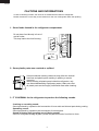
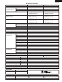
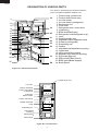
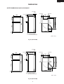
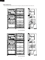
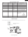
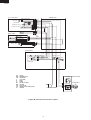
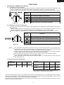
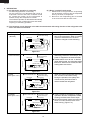
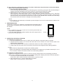
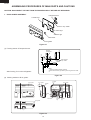
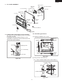
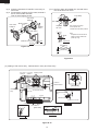
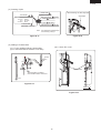
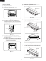
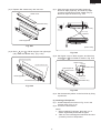
SJ-D30M
SJ-D33M
SERVICE MANUAL
S3404SE41APLT
REFRIGERATOR-FREEZER
MODELS
SJ-D30M-BL/GY/SLG
SJ-D33M-BL/GY/SLG
In the interests of user-safety (Required by safety regulations in some
countries) the set should be restored to its original condition and only
parts identical to those specified should be used.
DESTINATION .........................T
Refrigerant; HFC-134a
Refer to "HFC-134a COOLING UNIT" Service Manual for handling this refrigerant.
TABLE OF CONTENTS
page
CAUTIONS AND INFORMATIONS .................................................................................................................. 2
SPECIFICATIONS ............................................................................................................................................ 3
DESIGNATION OF VARIOUS PARTS ............................................................................................................. 4
DIMENSIONS ................................................................................................................................................... 5
LIST OF ELECTRICAL PARTS ........................................................................................................................ 7
WIRING DIAGRAM ........................................................................................................................................... 8
FUNCTIONS ................................................................................................................................................... 10
ASSEMBLING PROCEDURES OF MAIN PARTS AND CAUTIONS ............................................................. 13
COOLING UNIT .............................................................................................................................................. 19
REPLACEMENT PARTS LIST ....................................................................................................................... 21
SHARP CORPORATION
1
SJ-D30M
SJ-D33M
CAUTIONS AND INFORMATIONS
In case of following troubles, the cause is not related with the failure of refrigerator.
Please mention the correct way to the customer for the use of refrigerator when the repairing.
1. Some foods freezed in the refrigerator compartment.
Do not place food directly in front of
cold air outlet.
This may lead to the food freezing.
cold air flow
IN
OUT
2. Some plastic parts were cracked or splitted.
Some household cleaning chemicals may affect the internal
food liner and plastic parts resulting in splitting or cracks
occurring.
When cleaning all plastic parts inside this refrigerator, only
use diluted dishwashing liquid(soapy water). Make sure that
all plastic parts are thoroughly rinsed with water after cleaning.
3. IT IS NORMAL for the refrigerator to produce the following sounds.
Cracking or crunching sound;
Sound produced by expansion and contraction of inner walls and internal parts during cooling.
Squeaking sound;
Sound produced by expansion and contraction of internal parts.
Sound of flowing fluid (gurgling sound, fizzing sound);
Sound of refrigerant flowing in pipes (sound may become louder from time to time).
2
SJ-D30M
SJ-D33M
SPECIFICATIONS
Items
Type
Outer dimensions
(Including spacer)
Height
Width
Depth
Thai standard volume<TIS>
Rated storage volume <ISO>
(Rated volume)
Gross volume <ISO>
Defrosting
System
Start
Finish
Temperature control
No-frost freezer
Interior lamp
Caster
Evaporating pan
Refrigerator
Refrigerator tray
Compartment
Vegetable tray
Vegetable case
V parting plate
R door pocket
Egg tray
Bottle pocket
Bottle stopper
Door pocket
Fresh case
Bottle tray
Freezer
Freezer tray
Compartment
Ice cube maker
Ice storage box
Door pocket
Deodorizing unit
RATING
Items
Rated voltage
(V~)
Rated frequency
(Hz)
Climate class
Rated current
(A)
Rated input
(W)
Rated input of heating systems (W)
Refrigerant (Charging quantity) [Non-flammable]
Insulation blowing gas [Flammable]
Net Weight
(kg)
PLUG TYPE
Plug cord
2 pin
Destination mark
T
COLOR
Items
Outside color
Inside color
-BL
Blue
White
SJ-D30M
2-Door
1580mm(62.2")
650mm(25.6")
635mm(25.0")
360 liter (12.7cu.ft)
F: 109 liter (3.8 cu.ft)
R: 251 liter(8.9 cu.ft)
288 liter (10.2cu.ft)
F: 82liter (2.9 cu.ft)
R: 206 liter(7.3 cu.ft)
303 liter (10.7cu.ft)
F: 87liter (3.1 cu.ft)
R: 216 liter(7.6 cu.ft)
Heater system
Automatic
Automatic
Automatic (Adjustable)
Yes
1
2
1
2
1
1
1
1
1
1
1
2
1
1
1
Twin ice cube maker
1
2
2 ( Honeycomb type)
SJ-D33M
2-Door
1700mm(66.9")
650mm(25.6")
635mm(25.0")
400 liter (14.1 cu.ft)
F: 109 liter (3.8 cu.ft)
R: 291 liter(10.3 cu.ft)
321 liter (11.3 cu.ft)
F: 82 liter (2.9 cu.ft)
R: 239 liter(8.4 cu.ft)
336 liter (11.9 cu.ft)
F: 87 liter (3.1 cu.ft)
R: 249 liter(8.8 cu.ft)
SJ-D30M
220-240
50
T
1.1-1.2
145-154
128-152
HFC-134a(105g)
Cyclo pentane (HC)
60
SJ-D33M
Plug type
-GY
Gray
62
A-1
-SLG
Silver
3
SJ-D30M
SJ-D33M
DESIGNATION OF VARIOUS PARTS
The names in parenthesis are the denominations
used in the REPLACEMENT PARTS LIST.
18
1
2
3
19
4
5
6
7
5
8
10
9
10
11
12
13
14
15
20
21
22
23
24
19
16
17
20
1. Freezer temp. control knob
2. Freezer shelf(Freezer tray)
3. Ice cube maker
4. Ice cube box(Ice storage box)
5. Deodorizing unit
6. Fresh case
7. Refrigerator temp. control knob
8. Light(Lamp)
9. Bottle shelf(Bottle tray)
10. Refrigerator shelf(Refrigerator tray)
11. Lever
12. Shelf(Vegetable tray)
13. Vegetable crisper(Vegetable case)
14. Divider(V parting plate)
15. Evaporating pan
16. Casters
17. Adjustable foot(Adjustable leg ass’y)
18. Light switch
19. Utility pocket(Door pocket)
20. Magnetic door seal(Door packing)
21. Egg holder(Egg tray)
22. Egg pocket(R door pocket)
23. Bottle guard(Bottle stopper)
24. Bottle pocket
Figure D-1. External Description
Upper hinge cover
Fan motor
Defrost thermostat
F-temp. control knob
F-thermostat
Evaporator
Defrost heater
R-temp. control knob
Damper thermostat
Lamp
Evaporating pan
Compressor
Protector
Starting relay
Defrost timer
Figure D-2. Constructions
4
SJ-D30M
SJ-D33M
DIMENSIONS
OUTER DIMENSIONS AND CLEARANCE
more than
60
more than
650
more than
60
1
more than
650
60
992
1270
1580
1210
9.5
537.5
90
635
442
41
1150
1: Include the badge
Not include the handle
(Unit : mm)
Fig. E-1(SJ-D30M)
more than
60
650
more than
635
1
more than
60
more than
650
60
1270
1112
1210
1700
9.5
537.5
90
442
41
1150
1: Include the badge
Not include the handle
(Unit : mm)
Fig. E-2(SJ-D33M)
5
SJ-D30M
SJ-D33M
INNER DIMENSIONS
214
122
114
484
496
496
480
125
496
494
241
116
501
90
264
76
474
230
264
76
90
470
264
98
474
173
The dimensions between shelves can be changed by setting the shelves on the other rails.
281
474
474
85
481
256
85
179
470
474
484
114
480
125
166
501
90
230
214
90
122
474
173
Fig. E-3(SJ-D30M)
496
76
264
496
76
264
264
168
496
241
281
474
85
474
85
481
256
494
179
Fig. E-4(SJ-D33M)
6
SJ-D30M
SJ-D33M
LIST OF ELECTRICAL PARTS
ITEMS
Thermostat
TYPE NAME
MM1-9010
Defrost thermostat
Thermo. fuse
Fan motor
Defrost heater
Door switch
S101
SF70E
3R00121A
MM6-4264
SDKNA20101
Damper thermostat
Defrost timer
MM1-6173
ND1004M2
Lamp socket
Lamp
Compressor
—
—
FL1568SY
RATING
125V 6A
250V 3A
250V 8A
250V 10A
220-240V 50/60Hz
220-240V 378Ω
250V 0.25A
125V 0.5A
—
220-240V
50/60Hz
SPECIFICATIONS
(At normal notch)
ON/OFF : -19 / -24˚C
Open/Close : 8 / 1˚C
Working temp. : 70˚C
Working with ø100 fan
140W at 230V
3 terminals push-button type
Open/Close : 4.5 / 0˚C
Integration type
Cycle time : 10h44m/8h57m(50/60Hz)
Delay time : 4m20s/3m37s(50/60Hz)
E-14(Hard plastic body type)
E-14
Cooling capacity : 188W (50Hz)
Main coil : 13.3Ω
Common
Aux. coil : 25.6Ω
(at 25˚C)
250V 1A
240V 10W
220-240V/50Hz
Aux. coil
Starting relay
PET0SAT
Overload relay(Protector) 1.8C36A1
Main coil
22 Ω 300V
Open/ Close : 130/60˚C
—
—
WIRING DIAGRAM
Be sure to replace the electrical parts with specified ones for maintaining the safety and performance of the set.
GY
BR
OR
Y
R
P
BL
BK
SB
G-Y
W
: GRAY
: BROWN (live)
: ORANGE
: YELLOW
: RED
: PINK
: BLUE(neutral)
: BLACK
: SKY-BLUE
: GREEN-YELLOW (earth)
: WHITE
CONNECTED IN TERMINAL BOX
CONNECTOR
Defrost Timer
(BR)
(GY)
(R)
F-Thermostat
Plug / Cord
TM
Lamp
FM
L
Fan Motor
Thermo.Fuse
(SB)
(BK)
(Y)
Protector
(OR)
(W)
Door Switch
Defrost Heater
Defrost Thermo.
Compressor
C
M
A
(BL)
Starting relay(P.T.C relay)
Figure W-1. Wiring Diagram
7
SJ-D30M
SJ-D33M
Cabinet ass’y
E.V. cover ass’y
Lead EV-cover ass’y
Fan motor
FM
F-thermostat
Def thermo. ass’y
Thermo. fuse ass’y
Def. heater ass’y
GY-1
OR-1
R-1
BR-1
Y-1
BL-1
BK-1
W-1
1
5
2
6
3
7
4
8
1
5
2
6
3
7
4
8
1
2
(W-1)
1
2 Y-2
Door switch
C (NEUTRAL)
2 (PUSH OPEN)
1 (PUSH CLOSE)
BL-2
(OR-1)
SB-1
3
1
2
R lamp box ass’y
Lamp
10W
L
Lamp socket
1
2
1
2
BR-2
(SB-1)
Terminal box
TM
1
2
3
4
1
2
3
4
(Y-1)
(Y-2)
(BK-1)
(R-1)
GY-2
BLUE
BROWN
GRAY
EARTH
Defrost timer
GY
BR
OR
Y
R
P
BL
BK
SB
G-Y
W
: GRAY
: BROWN (live)
: ORANGE
: YELLOW
: RED
: PINK
: BLUE (neutral)
: BLACK
: SKY-BLUE
: GREEN-YELLOW (earth)
: WHITE
Protector
Terminal block
Compressor
E
C
M
A
Source cord
Starting
relay
Figure W-2. Electric Accessories Layout
8
SJ-D30M
SJ-D33M
FUNCTIONS
1. ADJUSTABLE TEMPERATURE CONTROL
(1) Temperature control of freezer
Thermostat (senses freezer temperature) operates on ON/OFF switchover to control the compressor and
cool air circulating fan , and allows the freezer temperature to keep at a suitable temperature.
However adjust the freezer temp. control knob as follows depending upon the storing condition of foods.
PURPOSE
KNOB
SETTING
MAX(Coldest)
For making ice rapidly or fast freezing.
When restocking with fresh food.
For normal freezing.
MED
For storing frozen food for a short period (up to one month).
When frozen food or ice cream is not stored.
MIN
Figure F-1.
(2) Temperature control of refrigerator
Damper-thermostat senses temperature of the refrigerator and changes the opening angle of the damper
automatically.
However, as the Damper-thermostat has no function to switch on or off the compressor and fan motor, the
freezer temperature control causes temperature in the refrigerator to vary to some extent.
However, adjust the refrigerator temp. control knob as follows depending upon the cooling condition.
PURPOSE
KNOB
SETTING
MAX(Coldest)
For keeping freshness of food longer.
When the refrigerator does not provide sufficient cooling.
For normal operation.
MED
When the refrigerator provides excessive cooling.
MIN
Figure F-2.
NOTE:
The refrigerator temperature is affected also by the freezer temperature. If the freezer temp.
control knob is set at the position "MAX", the temperature tends to be lower than the following
values, and if set at near the position "MIN", temperature tends to be higher.
If the refrigerator is operated for a long time with the freezer temperature control sets the "MAX"
position, foods stored in the refrigerator compartment may also freeze.
When refrigerator temperature control sets to the "MAX", some foods stored may freeze.
In this case adjust control set back to the "MED" position.
When refrigerator temperature control sets to the "MAX", some foods stored in Fresh case may
also become frozen.
(3) Reference value of temperature
SETTING OF
FREEZER TEMP.
CONTROL KNOB
MAX
(Coldest)
MED
MIN
Freezer
temperature
Approx.
-21
Approx.
-18
Approx.
-15
SETTING OF
REFRIGERATOR TEMP.
CONTROL KNOB
MAX
(Coldest)
MED
MIN
Refrigerator
temperature
Approx.
0
Approx.
3
Approx.
6
Fresh case
temperature
Approx.
-3
Approx.
1
Approx.
4
The values shown above refer to the case where the
freezer temp. control knob is set at "MED".
The values shown above refer to the measurement carried out center area and 1/3 of overall height from the bottom
at each of the refrigerator and the freezer after machine has been operated at an ambient temperature of 30˚C with no
food stored and the door closed until the temperature is stabilized.
The values vary depending upon frequency of opening and closing the door, ambient temperature, amount of stored
foods and manner of storing foods.
9
SJ-D30M
SJ-D33M
2. DEFROSTING
(1) No defrosting operation is necessary
No defrosting operation is necessary.
As this machine is so designed that a built-in
evaporator cools air and a fan circulates cooled
air, neither the freezer nor the refrigerator is
frosted, though the evaporator is frosted.
The frosted evaporator is defrosted automatically
due to the function of defrosting timer and heater,
requiring no defrosting operation.
(2) Where is melted frost brought
1. Melted frost is brought into the evaporating
pan at the back of the set and is evaporated
here by the heat of compressor.
2. Be sure to use Evaporating pan as inserted
so as to be level with the outer case.
(3) The following circuit diagrams in the table show automatic defrosting function of the refrigerator with
timer and defrost thermostat.
Operation
1. Cooling
(Normal)
Electric diagram
Defrost thermostat ON
Compressor running
Timer motor running
Thermo. fuse
Defrost heater
TM
Defrost
thermostat (ON)
COMP
Compressor
Timer contact
Timer motor
SOURCE
Thermostat
Description
The integration timer integrates running
time of the compressor. When it reaches
cycle time of defrost timer, the timer
contact is changed to start defrosting.
Figure F-3.
Defrost thermostat ON
(Time 20 to 30 min.)
Thermo. fuse
Defrost heater
TM
Defrost
thermostat (ON)
COMP
Compressor
Timer motor stops
Timer contact
Thermostat
SOURCE
Compressor stops
Timer motor
2. Defrosting
The timer contact is changed to start
defrosting, the timer motor stops, and
power is supplied to the defrost heater.
It takes about 20 to 30 min. to defrost.
When little frosted, the defrosting takes
little time. When much frosted, the defrosting takes much time.
Figure F-4 .
Defrost thermostat OFF
Thermo. fuse
Defrost heater
TM
Defrost
thermostat (OFF)
COMP
Compressor
Thermostat
SOURCE
Compressor stops
Timer motor running
Timer contact
(Time approx. 5 min.)
Timer motor
3. Drain
When the defrost thermostat becomes
OFF, the timer motor starts running.
During the operation time (delay time
of defrost time) defrosted water is
drained outside the refrigerator.
Figure F-5.
Defrost thermostat OFF
SOURCE
Thermostat
Compressor running
Timer motor stops
Timer contact
Thermo. fuse
Defrost heater
TM
Defrost
thermostat (OFF)
Figure F-6.
10
COMP
Compressor
(Time approx. 5 min.)
Timer motor
4. Restart
Timer contact is changed to cooling
operation and the compressor starts
running and the timer motor stops.
Defrost thermostat contact becomes ON
when it’s cooled. And the timer motor
starts running. (Figure F-3.)
SJ-D30M
SJ-D33M
(4) As a reference to determine the causes of trouble, malfunction and phenomena are described below.
Refer to the following when repairing.
1. Disconnection of defrost heater
As off-cycle defrosting is performed, the defrosting time is extremely prolonged. Each time defrosting is
started, the freezer temperature rises and a portion of ice and stored foods are melted.
2. Melted thermo. fuse or opened-circuit due to the defect of defrost thermostat.
When the above mentioned trouble occurs in cooling operation, the timer motor does not run, defrosting
will not take place, and consequently freezing is caused. In the above mentioned condition, when the timer
shaft is turned by hand to defrost, the timer motor runs during the operation time. However, the motor stops
from the time when the contact is changed, and freezing causes.
NOTE:
As the thermo. fuse assembly is intended to prevent dangers, do not use it under shorted condition even
for a short period.
3. DEW PREVENTION
The hot pipe, namely D.P.-condenser, is arranged around the flange part of
cabinet and the C-partition plate, preventing dew from being generated on
the cabinet.
NOTE:
D.P.-condenser pipe may be felt hot if touched by hand while the
compressor is in operation.
If you are asked about this, please explain that the hot pipe serve to
prevent the dew generation.
Hot pipe
Figure F-7
4. INSPECTION OF INITIAL STARTING
(1) Inspection of cooling unit
1. Set the temperature control knob to "MAX" and check that the compressor starts to operate.
2. Depress the door switch to run the fan and check that cool air is blown out of the cold air outlet of the
freezer and the refrigerator.
3. When the compressor does not work, check that the timer is not set to "defrost" position.
4 It takes about an hour and a half or two hours to put food in the refrigerator after starting operation.
NOTE:
After return the temperature control knob to "MED" position.
When the refrigerator is operated initially after installed, the compressor may vibrate excessively for 1 to 2
min. However, vibration becomes normal if it is continuously operated.
(2) Inspection of defrost device
Operate the refrigerator for 20 to 30 min. and then check the defrost device in the following procedures :
Allow 5 min. to restart the compressor since immediate starting after stopping will cause unsmooth operation.
1. Turn the timer shaft clockwise with a screw driver.
At this time, make certains the timer clinks and the compressor stops.
2. After more than 5 min., turn the shaft further to operate.
Make certain cooling operation is started again.
11
SJ-D30M
SJ-D33M
ASSEMBLING PROCEDURES OF MAIN PARTS AND CAUTIONS
CAUTION: DISCONNECT THE UNIT FROM THE POWER SUPPLY BEFORE ANY REPAIRING.
1. R-AIR GUIDER ASSEMBLY
Damper thermo.
A-sealer ag1
Thermo. cap. sealer
A-sealer ag3
A-sealer ag2
Dial sealer
R air guider
Figure A-1
Less than 130 mm
(1) Forming sensor of Damper thermo.
8 +1 mm
5 +1 mm
Damper
thermostat
Less than 12 mm
After forming, fix it to the refrigerator.
Stick thermo.
cap. sealer
10 + 2 mm
NOTE
Minimum bending radius is R5mm.
There should be no gas leak by reforming of sensor tube.
Figure A-2
(2) Sticking sealers to R air guider.
A-sealer
ag1
R air guider
DATUM
.
DATUM
OVERLAP 8mm
A-sealer
ag1
A-sealer
ag2
Dial sealer
R air guider
A-sealer
ag1
Figure A-3
12
A-sealer
ag3
A-sealer
ag1
214mm
R air guider
OVERLAP AREA
R air guider
SJ-D30M
SJ-D33M
2. E.V COVER ASSEMBLY
Motor cushion
Fan motor holder B
Fan motor
holder A
Propeller fan
100
E.v cover sealer C
E.v cover
Fan motor
Fan clamp
Defrost thermo.
ass’y
L-band C
U-sealer
handle
Lead EV-cover
ass’y
E.v cover
sealer C
E.v cover
sealer A
E.v cover
sealer B
Fuse ass’y
F-thermostat
C-insu sealer drr
Figure A-5
Figure A-4
2-2. Assembling procedures
2-1. Caution when removing E.V cover assembly
Be careful for removed Tapping screw not to fall to
the lower duct hole.
If Tapping screw falls, Damper thermo. in the
refrigerater compartment will be locked, and it will
become the cause of failure.
(1) Sticking of Sealers to E.V cover
14
E.v cover
sealer A
E.v cover
sealer C E.v cover
E.v cover
sealer C
Tapping screw
E.v cover assembly
E.v cover
20
20
E.v cover
sealer C
Duct hole
E.v cover
sealer C
E.v cover
sealer B
Figure A-6
(2) Fixing of Fan motor and Fan
Figure A-5
(2)-1 Stick U-sealer handle to Fan motor holder A.
Fan motor holder A
7 + 2mm
C
0 + 1mm
U-sealer handle
SEC. C-C
Figure A-7
13
C
U-sealer handle
SJ-D30M
SJ-D33M
(2)-2 Insert the terminals of Lead EV-cover ass'y to
Fan motor.
(2)-3 Fix two Motor cushions to Fan motor, and set it
at Fan motor holder A and B.
Then fix with Tapping screw.
(2)-4 Set Fan clamp to Propeller fan 100 and insert
it to the shaft of Fan motor.
Fan clamp
Fan motor
holder B
D
Fan clamp
Slit
Motor cushion
Fan motor
holder A
Propeller
fan 100
Tapping
screw
Fan motor
Slit of each Fan clamp
and Propeller fan
should not be at same position.
4 + 0.5mm
Note
Propeller fan should not be
taken out from shaft when
pulled by 3 kgf.
Shaft
Lead EV-cover ass’y
Detail of D
RED
BROWN
Fan clamp
Figure A-8
Propeller fan
Figure A-9
(3) Setting of Fan motor ass'y , Defrost thermo. ass'y and Fuse ass'y.
E.v cover
sealer A
E.v cover
sealer C
Tapping screw
more than 3.5mm
more than 3.5mm
25
25
L-band C
20
F
Defrost thermo.
Tapping
screw
[front side]
AL tape
Lead e.v cover
ass’y
Set metal side below
CUT
AL tape
25
Defrost thermo.
ass’y
30
10 + 5mm
F
AL tape
L-band C
Z G
Not come out of claw.
Fuse ass’y
C-insu sealer drr
40
SEC. F F
Z
AL tape
C-insu sealer drr
AL tape
Fuse ass’y
20
[back side]
Detail of G
SEC. Z Z
Figure A-10
14
SJ-D30M
SJ-D33M
(4) Inserting of pins
After inserting, fix with vinyl tape.
F-thermostat 2
(RED, inserted)
Defrost thermo. 3 (PINK)
Fuse 8 (WHITE)
Fan motor 1 , 5
WIRE COLOR FOR FAN MOTOR
100-110V : WHITE
127V : YELLOW
220-240V : BLUE
1
2
3
4
5
6
7
8
F-thermostat 6
(BROWN, inserted)
Vinyl tape
Fuse 8 (BLACK)
Defrost thermo. 7 (BLUE)
Note
Pins should be inserted surely,
and check by pulling it.
Figure A-11
Figure A-12
(5) Setting of F-thermostat
(5)-3 Set to E.V cover.
(5)-1 Form capillary tube of F-thermostat.
(5)-2 Insert terminal of Lead EV-cover ass'y.
B
7mm
BROWN
RED
35mm
15mm
10mm
7mm
30mm
F-thermostat
Note
・Bending radius of capillary
tube should be R5mm to R10mm.
15mm
Figure A-13
B
SEC. B B
Figure A-14
15
SJ-D30M
SJ-D33M
(2) Replacement of Def. heater ass'y.
(2)-1 Take Drain support al off from the food liner.
3. DEFROST HEATER
(1) Taking-out Evaporator
(1)-1. Take out E.v cover ass'y (Fig. A-15).
Drain support al
Evaporator
Food liner convex part
Fig. A-18
Fig. A-15
(2)-2 Raise the protrusion part of Drain support al.
Then remove Heater cover.
(1)-2. As shown in Fig. A-16, pull the upper part of
Evaporator toward you, pull it diagonally so that
the pipe of Evaporator does not contact the convex
part of food liner.
Protrusion parts
Food liner convex part
Drain support al
Evaporator
Pipe
Heater cover
Protrusion part of Drain support al(2 pcs.)
Fig. A-16
(1)-3. As shown in Fig. A-17, bend the removed
Evaporator horizontally so that Defrost heater can
be replaced easily.
NOTE: When pulling Evaporator and bending the
pipes, pay attention so as not to break and
deform the pipes. Still, take care not to hurt
yourself by fin of Evaporator.
Def. heater ass’y
Heater cover
Fig. A-19
(2)-3 Open Def.heater fixed part of Drain support al to
the right and left, then remove Def.heater ass'y.
Evaporator
Fixed parts
Fig. A-17
Drain support al
Def.heater ass’y
Fig. A-20
16
SJ-D30M
SJ-D33M
(2)-4. Replace Def. heater ass'y with new one.
(2)-7. Stick the longer wire to the Drain support by
aluminum tape (2 pieces), and wind vinyl tape
(2 pieces) to lead wires of Def. heater ass'y by
aluminum tape as shown in Fig. A-23.
Heater cover
A
Def.heater ass’y
A
Sec. AA
[back side]
aluminum tape
(W25 X L40)
Drain support al
Fig. A-21
[bottom side]
(2)-6. Bend a and b of Drain support al to right angle
(90˚) to set Def. heater ass'y. (Fig. A-22)
Fig. A-23
(2)-8. Set Heater cover on Drain support, and bend top
edge c and d to outside as shown in Fig. A-24.
This side is longer wire
Heater cover
a
top edge
This side is shorter wire
Def.heater ass’y
Drain support al
Heater cover
c
Drain support al
Sec. BB
Def.heater ass’y
b
B
d
Def.heater ass’y
B
Fig. A-22
Fig. A-24
(2)-9. Set the assembly above on the food liner by fixing
a protrusion.
(3) Installing of Evaporator
(3)-1. Install Evaporator as shown in Fig. A-15 in the
reverse order of Fig. A-16.
(3)-2. Correct the deformed fin.
NOTE
1. When installing Evaporator, take care not to
deform significantly and break the pipes.
2. Take care not to damage the lead wires and hurt
yourself by the fin of Evaporator.
17
SJ-D30M
SJ-D33M
COOLING UNIT
Mark: Refrigerant flow
Mark: Brazing portion
Hot pipe L
(Side condenser)
Hot pipe
(DP-condenser)
Hot pipe R
(Side condenser)
Evaporator
Back condenser
Suction pipe
Eva-pan pipe
Compressor
Capillary tube
Dryer
Figure C-1. Cooling unit
18
SJ-D30M
SJ-D33M
Dryer
Capillary tube
Charge pipe
Hot pipe
Evaporator
Charge pipe
Compressor
Suction pipe
S.P. connector
Eva-pan pipe
Back condenser
Figure C-2. Location
From Eva-pan pipe ass’y
to Back condenser In
From Back condenser out
to Hot pipe
From Compressor
to Discharge p connector
From Suction pipe
to SP connector
From Hot pipe
to Dryer
From Dryer
to Capillary tube
From SP connector
to Compressor
From Compressor
to Charge pipe
Figure C-3. Location
19
From Discharge p connector
to Eva-pan pipe ass’y