1
www.seuservice.com
1st PRINTING NOV 01
OWNER’S MANUAL
SEGA ENTERPRISES, INC. USA
MANUAL NO. 999-1375
VISIT OUR WEBSITE!
BEFORE USING THE PRODUCT, BE SURE TO READ THE FOLLOWING:
To maintain the safety:
To ensure the safe usage of the product, be sure to read the following before using the product. The following
instructions are intended for the users, operators and the personnel in charge of the operation of the product.
After carefully reading and sufficiently understanding the warning displays and cautions, handle the product
appropriately. Be sure to keep this manual nearby the product or elsewhere convenient for referring to it
when necessary.
Herein, explanations which require special attention are enclosed with dual lines. Depending on the potentially hazardous degrees, the terms of WARNING, CAUTION, etc. are used. Be sure to understand the
contents of the displays before reading the text.
Indicates that mishandling the
product by disregarding this
warning will cause a potentially
hazardous situation which can
result in death or serious injury.
Indicates that mishandling the product
by disregarding this caution will cause
a slight hazardous situation which can
result in personal injury and or material
damage.
For the sage usage of the product, the following pictographs are used:
Indicates “HANDLE WITH CARE.” In order to protect the human body an equipment, this
display is attached to places where the Owner’s Manual and or Service Manual should be referred
to.
Perform work in accordance with the instructions herein stated.
Instructions for work are explained by paying attention to the aspect of accident prevention. Failing to
perform work as per the instructions can cause accidents. In the case where only those who have technical expertise should perform the work to avoid hazardous situation, the instructions herein state that the
serviceman should perform such work.
Be sure to turn off power before working on the machine.
To prevent electric shock, be sure to turn off power before starting the work in which the worker touches
the interior of the product. If the work is to be performed in the power-on status, the Instruction Manual
herein always states to that effect.
Be sure to ground the Earth Terminal (this, however, is not required in the case where a power cord
with earth is used).
This product is equipped with the Earth Terminal. When installing the product, Connect the Earth Terminal to the “accurately grounded indoor earth terminal” by using an earth wire. Unless the product is
grounded appropriately, the user can be subject to electric shock. After performing repair, etc. for the
Control equipment, ensure that the Earth Wire is firmly connected to the Control equipment.
Ensure that the Power Supply used is equipped with an Earth Leakage Breaker.
This product does not incorporate the Earth Leakage Breaker. Using a power supply which is not
equipped with the Earth Leakage Breaker can cause a fire when earth leakage occurs.
Be sure to use fuses which meet the specified rating. (only for the machines which use fuses).
Using fuses exceeding the specified rating can cause a fire and electric shock.
Specification changes (removal of equipment, conversion and addition) not designated by SEGA
are not allowed.
The parts of the product include warning labels for safety, covers for personal protection, etc. It is very
hazardous to operate the product by removing parts and or modifying the circuits. Should doors, lids
and protective parts be damaged or lost, refrain from operating the product, and contact where the
product was purchased from or the office herein stated. SEGA shall not be held responsible for any
accidents, compensation for damage to a third party, resulting from the specifications not designated by
SEGA.
Ensure that the product meets the requirements of appropriate Electrical Specifications.
Before installing the product, check for Electrical Specifications. SEGA products have a nameplate on
which Electrical Specifications are described. Ensure that the product is compatible with the power
supply voltage and frequency requirements of the location. Using any Electrical Specifications different
from the designated Specifications can cause a fire and electric shock.
Install and operate the product in places where appropriate lighting is available, allowing warning
labels to be clearly read.
To ensure safety for the customers, labels and printed instructions describing potentially hazardous
situation are applied to places where accidents can be caused. Ensure that where the product is operated
has sufficient lighting allowing the warnings to be read. If any label is peeled off, apply it again immediately. Please place an order with where the product was purchased from or the office herein stated.
When handling the Monitor, be very careful. (Applies only to the product w/monitor.)
Some of the monitor (TV) parts are subject to high tension voltage. Even after running off power, some
portions are still subject to high tension voltage sometimes. Monitor repair and replacement should be
performed only be those technical personnel who have knowledge of electricity and technical expertise.
Be sure to adjust the monitor (projector) properly. (Applies only to the product w/monitor.)
Do not operate the product leaving on-screen flickering or blurring as it is. Using the product with the
monitor not properly adjusted may cause dizziness or a headache to an operator, a player, or the customers.
When transporting or reselling this product, be sure to attach this manual to the product.
In the case where commercially available monitors and printers are used in this product, only the
contents relating to this product are explained herein. Some commercially available equipment has
functions and reactions not stated in this manual. Read this manual together with the specific Instruction Manual of such equipment.
• Descriptions herein contained may be subject to improvement changes without notice.
• The contents described herein are fully prepared with due care. However, should any question arise or
errors be found, please contact SEGA.
INSPECTIONS IMMEDIATELY AFTER TRANSPORTING THE PRODUCT TO THE LOCATION.
Normally, at the time of shipment, SEGA products are in a status allowing for usage immediately after
transporting to the location. Nevertheless, an irregular situation may occur during transportation. Before
turning on power, check the following points to ensure that the product has been transported in a satisfactory status.
Are there any dented portions or defects (cuts, etc.) on the external surfaces of the cabinet?
Are Casters and Adjusters, damaged?
Do the power supply voltage and frequency requirements meet with those of the location?
Are all wiring connectors correctly and securely connected? Unless connected in the correct direction,
connector connections can not be made accurately. Do not insert connectors forcibly.
Do power cords have cuts and dents?
Do the fuses used meet specified rating? Is the Circuit Protector in an energized status?
Are all accessories available?
Can all Doors and Lids be opened with the Accessory keys? Can Doors and Lids be firmly closed?
TABLE OF CONTENTS
BEFORE USING THE PRODUCT, BE SURE TO READ THE FOLLOWING:
TABLE OF CONTENTS
INTRODUCTION OF THE OWNER'S MANUAL
1. HANDLING PRECAUTIONS ......................................................................................1
2. PRECAUTIONS CONCERNING INSTALLATION LOCATION ..............................3
3. OPERATION .................................................................................................................5
4. NAME OF PARTS .......................................................................................................10
5. ACCESSORIES ...........................................................................................................11
6. ASSEMBLING AND INSTALLATION .....................................................................16
7. PRECAUTIONS TO BE HEEDED WHEN MOVING THE MACHINE .................. 29
8. CONTENTS OF GAME ..............................................................................................31
9. EXPLANATION OF TEST AND DATA DISPLAY ..................................................38
9 - 1 SWITCH UNIT AND COIN METER ................................................................39
9 - 2 SYSTEM TEST MODE ......................................................................................41
9 - 3 GAME TEST MODE ..........................................................................................40
10. AIR DRIVE ..................................................................................................................57
10 - 1 OVERVIEW OF AIR DRIVE SYSTEM ...........................................................58
10 - 2 DEWATERING FROM THE AIR FILTER .......................................................59
10 - 3 DEWATERING FROM THE AIR TANK ......................................................... 60
10 - 4 REGULATOR .....................................................................................................61
10 - 5 AIR CLEANER ..................................................................................................62
11. MAINTENANCE OF MECHANISM UNIT ............................................................... 63
11 - 1 REMOVE THE LID & THE BELLOWS
BEFORE SARTING MAINTENANCE WORK ................................................ 64
11 - 2 GREASING AND RETIGHTENING THE BOLTS .......................................... 69
11 - 3 ADJUSTMENT AND REPLACEMENT OF PITCH VOLUME ......................71
11 - 4 REMOVE THE INCLINATION SENSOR ........................................................72
12. HANDLE MECHANISM ............................................................................................74
12 - 1 ADJUSTING AND REPLACING THE THROTTLE V.R. ...............................74
12 - 2 ADJUSTING OR REPLACING THE HANDLE V.R. ......................................77
12 - 3 GREASING ......................................................................................................... 79
13. COIN SELECTOR .......................................................................................................80
14. PROJECTOR ................................................................................................................84
14 - 1 CLEANING THE SCREEN ...............................................................................84
14 - 2 ADJUSTMENT OF TOSHIBA PROJECTOR ................................................... 85
15. REPLACEMENT OF FLUORESCENT LAMP ..........................................................95
16. PERIODIC INSPECTION TABLE .............................................................................96
17. TROUBLESHOOTING ...............................................................................................97
17 - 1 TROUBLESHOOTING ......................................................................................97
17 - 2 ERROR MESSAGE ..........................................................................................101
18. GAME BOARD .........................................................................................................103
18 - 1 REMOVING THE GAME BOARD .................................................................103
18 - 2 COMPOSITION OF GAME BOARD ..............................................................105
19. DESIGN RELATED PARTS ..................................................................................... 106
20. COMMUNICATION PLAY ......................................................................................109
20 - 1 INSTALLATION PRECAUTIONS ................................................................ 109
20 - 2 CONNECTING THE COMMUNICATION CABLE ..................................... 110
20 - 3 SETTING FOR COMMUNICATION PLAY ................................................. 114
20 - 4 CAUTIONS TO BE HEEDED DURING COMMUNICATION PLAY ........115
21. PARTS LIST ..............................................................................................................116
22. WIRE COLOR CODE TABLE .................................................................................. 171
23. WIRING DIAGRAM ................................................................................................. XX
24. PIPING DIAGRAM ................................................................................................... XX
SPECIFICATIONS
Installation space
Height
Weight
Power, maximum current
For TAIWAN
Power, current
MONITOR
: 56in [1,435 mm] (W) X 123in[3120 mm] (D)
: 87.4 in. [2,220 mm]
: 1,194 lbs. [543 kg.]
: 1,250 W 11.5 A (AC 120V 60 Hz AREA)
1,150 W 6.4 A (AC 220V 50 Hz AREA)
1,240 W 7.0 A (AC 220V 60 Hz AREA)
1,150 W 5.8 A (AC 230V 50 Hz AREA)
1,140 W 5.6 A (AC 240V 50 Hz AREA)
: 1,250 W 12.5 A (MAX.)
750 W 7.0 A (MIN.)
: 50 TYPE PROJECTION DISPLAY
INTRODUCTION OF THE OWNER'S MANUAL
This Owner's Manual is intended to provide detailed descriptions together with all the
necessary information covering the general operation of electronic assemblies,
electromechanicals, servicing control, spare parts, etc. as regards the product,
WAVERUNNER GP.
This manual is intended for the owners, personnel and managers in charge of operation
of the product. Operate the product after carefully reading and sufficiently
understanding the instructions. If the product fails to function satisfactorily, nontechnical personnel should under no circumstances touch the internal system. Should
any malfunctioning occur, turn the power off and unplug the Power Cord (AC Cable),
and contact where the product was purchased from.
Use of this product is unlikely to cause physical injuries or damages to property. However,
where special attention is required this is indicated by a thick line, the word "IMPORTANT"
and its sign in this manual.
Indicates that mishandling the product by disregarding this display can cause the
product's intrinsic performance not to be obtained, resulting in malfunctioning.
SEGA ENTERPRISES, INC. (U.S.A.)/CUSTOMER SERVICE
45133 Industrial Drive, Fremont, California 94538, U.S.A.
Phone: (415) 701-6580
Facsimile: (415) 701-6594
DEFINITION OF LOCATION'S MAINTENANCE MAN AND SERVICEMAN
Non-technical personnel who do not have technical knowledge and expertise
should refrain from performing such work that this manual requires the location's
maintenance man or a serviceman to carry out, or work which is not explained in
this manual. Failing to comply with this instruction can cause a severe accident
such as electric shock.
Ensure that parts replacement, servicing & inspections, and troubleshooting are performed by the
location's maintenance man or the serviceman. It is instructed herein that particularly hazardous
work should be performed by the serviceman who has technical expertise and knowledge.
The location's maintenance man and serviceman are herein defined as follows:
"Location's Maintenance Man" :
Those who have experience in the maintenance of amusement equipment and vending machines,
etc., and also participate in the servicing and control of the equipment through such routine work
as equipment assembly and installation, servicing and inspections, replacement of units and
consumables, etc. within the Amusement Facilities and or locations under the management of the
Owner and Owner's Operators of the product.
Activities of Location's Maintenance Man :
Assembly & installation, servicing & inspections, and replacement of units & consumables as
regards amusement equipment, vending machines, etc.
Serviceman :
Those who participate in the designing, manufacturing, inspections and maintenance service of
the equipment at an amusement equipment manufacturer.
Those who have technical expertise equivalent to that of technical high school graduates as regards electricity, electronics and or mechanical engineering, and daily take part in the servicing &
control and repair of amusement equipment.
Serviceman's Activities :
Assembly & installation and repair & adjustments of electrical, electronic and mechanical parts of
amusement equipment and vending machines.
General Precautions
Follow Instructions: All operating and use instructions should be followed.
Attachments: Do not use attachments not recommended by the product manufacturer as they may cause hazards.
Accessories: Do not place this product on an unstable cart, stand, tripod, bracket, or table. The product may fall,
causing serious injury to a child or adult, and serious damage to the product. Use only with a cart, stand, tripod, bracket, or
table recommended by the manufacturer, or sold with the product. Any mounting of the product should follow the
manufacturer’s instructions, and should use only mounting accessories recommended by the manufacturer.
Moving the Product: This product should be moved with care. Quick stops, excessive force, and uneven surfaces
may cause the product to overturn.
Ventilation: Slots and openings in the cabinet are provided for ventilation, to ensure reliable operation of the product
and to protect it from overheating; these openings must not be blocked or covered. The openings should never be blocked
by placing the product in a built-in installation such as a bookcase or rack unless proper ventilation is provided or the
manufacturer’s instructions have been adhered to.
Power Sources: This product should be operated only from the type of power source indicated on the marking label.
If you are not sure of the type of power supply to your location, consult your local power company. For products intended
to operate from battery power or other sources, refer to the operating instructions.
Grounding or Polarization: This product is equipped with a three-wire grounding-type plug, a plug having a third
(grounding) pin. This plug will only fit into a grounding-type power outlet. This is a safety feature. If you are unable to
insert the plug into the outlet, contact your electrician to replace your obsolete outlet. Do not defeat the safety purpose of the
grounding-type plug.
Power Cord Protection: Power-supply cords should be routed so that they are not likely to be walked on or pinched
by items placed upon or against them, paying particular attention to cords at plugs, convenience receptacles, and the point
where they exit from the product.
Overloading: Do not overload wall outlets, extension cords, or integral convenience receptacles as this can result in
a risk of fire or electric shock.
Object and Liquid Entry: Never push objects of any kind into this product through openings as they may touch
dangerous voltage points or short-out parts that could result in a fire or electric shock. Never spill liquid of any kind on the
product.
Servicing: Do not attempt to service this product yourself as opening or removing covers may expose you to dangerous voltage or other hazards. Refer all servicing to qualified service personnel.
Damage Requiring Service: Unplug this product from the wall outlet and refer servicing to qualified service personnel under the following conditions:
a) If the power cord or plug is damaged;
b) If liquid has been spilled, or objects have fallen into the product;
c) If the product has been exposed to rain or water;
d) If the product does not operate normally when following the operating instructions. Adjust only those controls that
are explained in the operating instructions. An improper adjustment of other controls may result in damage and will
often require extensive work by a qualified technician to restore the product to its normal operation;
e) If the product has been dropped or damaged in any way;
f) When the product exhibits a distinct change in performance; this indicates a need for service.
Replacement Parts: When replacement parts are required, be sure the service technician has used replacements parts
specified by the manufacturer or that have the same characteristics as the original part. Unauthorized substitutions may
result in fire, electric shock, or other hazards.
Safety Check: Upon completion of any service or repairs to this product, ask the service technician to perform safety
checks to determine that the product is in proper operating condition.
Heat: The product should be situated away from heat sources such as radiators, heat registers, stoves, or other products (including amplifiers) that produce heat.
Lithium Battery- Dispose of batteries only in accordance with the battery manufacturer’s recommendations.
Do not dispose in an open flame condition, since the battery may explode.
Cleaning: When cleaning the monitor glass, use water or glass cleaner and a soft cloth. Do not apply chemicals such
as benzine, thinner, etc.
Location: This an indoor game machine, DO NOT install it outside. To ensure proper usage, avoid installing indoors
in the places mentioned below:
• Places subject to rain/water leakage, or condensation due to humidity;
• In close proximity to a potential wet area;
• Locations receiving direct sunlight;
• Places close to heating units or hot air;
•In the vicinity of highly inflammable/volatile chemicals or hazardous matter;
• On sloped surfaces;
• In the vicinity of emergency response facilities such as fire exits and fire extinguishers;
• Places subject to any type of violent impact;
• Dusty places.
INSTALLATION PRECAUTIONS
• Verify the amperage of the branch circuit outlet before plugging in the power plug. Do not overload the circuit.
• Avoid using an extension cord. If one is required, use an extension cord of type SJT, 16/3 AWG
rated min. 120 VAC, 7A.
• Moving this unit requires a minimum clearance (of doors, etc.) of 32” (W) by 77” (H).
• For the operation of this machine, secure a minimum area of 64” (W) by 97”(D).
REGULATORY APPROVALS
This game has been tested and found to comply with the Federal Communications Commission Rules.
This device complies with Part 15 of the FCC Rules. Operation is subject to the following two conditions: (1) This
device may not cause harmful interference, and (2) this device must accept any interference received, including interference
that may cause undesired operation.
This game has been tested and listed by Underwriters Laboratories, Inc., to ANSI/UL22.
LISTED
UL
5K92
®
AMUSEMENT MACHINE
1. HANDLING PRECAUTIONS
When installing or inspecting the machine, be very careful of the following points and pay
attention to ensure that the player can enjoy the game safely.
Non-compliance with the following points or inappropriate handling running counter to the
cautionary matters herein stated can cause personal injury or damage to the machine.
Before performing work, be sure to turn power off. Performing the work
without turning power off can cause an electric shock or short circuit. In the
case work should be performed in the status of power on, this manual always
states to that effect.
To avoid electric shock or short circuit, do not plug in or unplug quickly.
To avoid electric shock, do not plug in or unplug with a wet hand.
Do not expose Power Cords and Earth Wires on the surface, (floor, passage,
etc.). If exposed, the Power Cords and Earth Wires are susceptible to damage.
Damaged cords and wires can cause electric shock or short circuit.
To avoid causing a fire or electric shock, do not put things on or damage
Power Cords.
When or after installing the product, do not unnecessarily pull the power cord.
If damaged, the power cord can cause a fire or electric shock.
In case the power cord is damaged, ask for replacement through where the
product was purchased from or the office herein stated. Using the cord as is
damaged can cause fire, electric shock or leakage.
Be sure to perform grounding appropriately. Inappropriate grounding can
cause an electric shock.
Be sure to use fuses meeting specified rating. Using fuses exceeding the
specified rating can cause a fire or electric shock.
Completely make connector connections for IC BD and others. Insufficient
insertion can cause an electric shock.
Specification changes, removal of equipment, conversion and/or addition, not
designated by SEGA are not permitted.
• Failure to observe this may cause a fire or an electric shock. Non-compliance
with this instruction can have a bad influence upon physical conditions of the
players or the lookers-on, or result in injury during play.
• SEGA shall not be held responsible for damage, compensation for damage to
a third party, caused by specification changes not designated by SEGA.
Be sure to perform periodic maintenance inspections herein stated.
1
www.seuservice.com
STOP
IMPORTANT
For the IC board circuit inspections, only the logic tester is allowed. The use
of a multiple-purpose tester is not permitted, so be careful in this regard.
The Projector is employed for this machine. The Projector's screen is
susceptible to damage, therefore, be very careful when cleaning the screen.
For details, refer to PROJECTOR.
Some parts are the ones designed and manufactured not specifically for this
game machine. The manufacturers may discontinue, or change the
specifications of, such general-purpose parts. If this is the case, Sega cannot
repair or replace a failed game machine whether or not a warranty period has
expired.
www.seuservice.com
2
2. PRECAUTIONS CONCERNING INSTALLATION
LOCATION
This product is an indoor game machine. Do not install it outside. Even indoors,
avoid installing in places mentioned below so as not to cause a fire, electric shock,
injury and or malfunctioning.
Places subject to rain or water leakage, or places subject to high humidity in
the proximity of an indoor swimming pool and or shower, etc.
Places subject to direct sunlight, or places subject to high temperatures in the
proximity of heating units, etc.
Places filled with inflammable gas or vicinity of highly inflammable/volatile
chemicals or hazardous matter.
Dusty places.
Sloped surfaces.
Places subject to any type of violent impact.
Vicinity of anti-disaster facilities such as fire exits and fire extinguishers.
The operating (ambient) temperature range is from 5˚ to 30˚.
LIMITATIONS OF USAGE REQUIREMENTS
Be sure to check the Electrical Specifications.
Ensure that this product is compatible with the location's power supply,
voltage and frequency requirements.
A plate describing Electrical Specifications is attached to the product.
Non-compliance with the Electrical Specifications can cause a fire and
electric shock.
This product requires the Breaker and Earth Mechanisms as part of the
location facilities. Using them in a manner not independent can cause a fire
and electric shock.
Ensure that the indoor wiring for the power supply is rated at 15A or higher
(AC single phase 100 ~ 120V area), and 8A or higher (AC 220 ~ 240V area).
Non-compliance with the Electrical Specifications can cause a fire and
electric shock.
Be sure to independently use the power supply equipped with the Earth
Leakage Breaker. Using a power supply without the Earth Leakage Breaker
can cause an outbreak of fire when earth leakage occurs.
Putting many loads on one electrical outlet can cause generation of heat and a
fire
resulting from overload.
When using an extension cord, ensure that the cord is rated at 15A or higher
(AC 100 ~ 120V area) and 8A or higher (AC 220 ~ 240V area). Using a cord
rated lower than the specified rating can cause a fire and electric shock.
3
www.seuservice.com
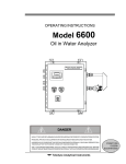
OPERATION AREA
For the operation of this machine, secure a minimum area of 1.6m (W) X
3.1m (D). In order to prevent injury resulting from the falling down accident
during game play, be sure to secure the minimum area for operation.
Be sure to provide sufficient space so as to allow this product's ventilation fan
to function efficiently. To avoid machine malfunctioning and a fire, do not
place any obstacles near the ventilation opening.
SEGA shall not be held responsible for damage, compensation for damage to
a third party, resulting from the failure to observe this instruction.
123456789012345678901234567890121234
123456789012345678901234567890121234
123456789012345678901234567890121234
123456789012345678901234567890121234
1234
1234
1234 15cm
1234
1234
1234 6 inches
1234
1234
1234
1234
1234
1234
1234
1234
1234
1234
1234
1234
1234
1234
1234
1234
1234
1234
1234
1234
1234
1234
1234
1234
1234
1234
1234
1234
1234
1234
1234
1234
1234
1234
1234
1234
1234
1234
1234
1234
1234
1234
1234
Electric current consumption
3.55m
MAX. 11.5 A (AC 120V 60 Hz)
MAX. 6.4 A (AC 220V 50 Hz)
MAX. 7.0 A (AC 220V 60 Hz)
MAX. 5.8 A (AC 230V 50 Hz)
MAX. 5.6 A (AC 240V 50 Hz)
MAX. 12.5 A (For TAIWAN)
1.6m
63 inches
FIG. 2
www.seuservice.com
4
140 inches
For transporting the machine into the location's building, the minimum necessary
dimensions of the opening (of doors, etc.) are 1.45m(W) and 1.68m(H).
3. OPERATION
PRECAUTIONS TO BE HEEDED BEFORE STARTING THE OPERATION
To avoid injury and trouble, be sure to constantly give careful attention to the behavior and
manner of the visitors and players.
In order to avoid accidents, check the following before starting the operation:
To ensure maximum safety for the players and the customers, ensure that
where the product is operated has sufficient lighting to allow any warnings to
be read. Operation under insufficient lighting can cause bodily contact with
each other, hitting accident, and or trouble between customers.
Be sure to perform appropriate adjustment of the monitor (projector). For
operation of this machine, do not leave monitor's flickering or deviation as is.
Failure to observe this can have a bad influence upon the players' or the
customers' physical conditions.
It is suggested to ensure a space allowing the players who feel sick while
playing the game to take a rest.
Check if all of the adjusters are in contact with the
surface. If they are not, the Cabinet can move and
cause an accident.
Check to see if the bottom bellows are damaged or
omitted. Bellows are important hazard-prevention
parts. Irregular bellows can cause injury.
Check bellows.
Ensure that all of the Adjusters are in contact with the floor.
Safety Sensor
Before commencing operation,
execute test run to check if the
Safety Sensor and the Motion
Stop Switch are satisfactorily
functioning to stop the
machine movements during
game. The Safety Sensor and
the Motion Stop Switch are
important hazard-prevention
parts. Irregular important
parts can cause injury.
Check for the Safety Sensor's
function to stop movements.
5
Motion Stop Switch
www.seuservice.com
Do not put any heavy item on this product. Placing any heavy item on the
product can cause a falling down accident or parts damage.
Do not climb on the product. Climbing on the product can cause falling down
accidents. To check the top portion of the product, use a step.
To avoid electric shock, check to see if door & cover parts are damaged or
omitted.
To avoid electric shock, short circuit and or parts damage, do not put the
following items on or in the periphery of the product.
Flower vases, flowerpots, cups, water tanks, cosmetics, and receptacles/
containers/vessels containing chemicals and water.
To avoid injury, be sure to provide sufficient space by considering the potentially
crowded situation at the installation location. Insufficient installation space can
cause making bodily contact with each other, hitting accidents, and or trouble
between customers.
Be sure to periodically dewater the Air Drive and dispose of the drain water.
Excessively gathered water can cause the Air Drive Mechanism to malfunction
and get out of order.
DRAIN TUBE
FILTER
www.seuservice.com
6
WATER TANK
PRECAUTIONS TO BE HEEDED DURING OPERATION (PAYING ATTENTION TO CUSTOMERS)
To avoid injury and trouble, be sure to constantly give careful attention to the behavior and
manner of the visitors and players.
To avoid injury and accidents, those who fall under the following categories
are not allowed to play the game.
• Those who need assistance such as the use of an apparatus when walking.
• Those who have high blood pressure or a heart problem.
• Those who have experienced muscle convulsion or loss of consciousness when
playing video game, etc.
• Those who have a trouble in the neck and or spinal cord.
• Intoxicated persons.
• Pregnant women or those who are in the likelihood of pregnancy.
• Persons susceptible to motion sickness.
• Persons whose act runs counter to the product's warning displays.
A player who has never been adversely affected by light stimulus might
experience dizziness or headache depending on his physical condition when
playing the game. Especially, small children can be subject to those
conditions. Caution guardians of small children to keep watch on their
children during play.
Instruct those who feel sick during play to have a medical examination.
To avoid electric shock and short circuit, do not allow customers to put hands
and fingers or extraneous matter in the openings of the product or small
openings in or around the doors.
To avoid falling down and injury resulting from falling down, immediately
stop the customer's leaning against or climbing on the product, etc.
To avoid electric shock and short circuit, do not allow the customers to
unplug the power plug without a justifiable reason.
The player whose feet can not be
placed on the base could fall
down and cause injury. To avoid
injury, instruct persons of short
stature to refrain from playing the
game.
7
www.seuservice.com
To avoid injury and parts
damage, instruct players that only
up to two persons are allowed to
ride.
To avoid injury resulting from
falling down, and electric shock
due to spilled drinks, instruct the
player not to place heavy items or
drinks on the product.
Do not place drinks
on the base!
Instruct the player to take a firm
grip of the handle Bars during
play. This machine reacts as per
the contents of the game. To
avoid injury, instruct the players
to refrain from single-handed
taking grip of the handle Bar
(which is very likely to cause
potentially hazardous situation,
should he attempt to do so).
To avoid injury and trouble
resulting from coming into
contact with each other, instruct
persons other than the players to
keep away from the mechanism
base. The Safety Sensor
functions to stop only the
machine movement from the
Compressor. The ride can be
moved by the player.
www.seuservice.com
8
Immediately stop such violent acts as hitting and kicking the product. Such
violent acts can cause parts damage or falling down, resulting in injury due to
fragments and falling down.
When riding in tandem,
firmly hold on to the front
player. To avoid injury, do
not stand driving the ride.
9
www.seuservice.com
BILLBOARD
4. NAME OF PARTS
PTV 50 TYPE PROJECTOR
FRONT CABINET
RIDE
FIG. 4 a
COMPRESSOR BOX
C O I N
CHUTE
DOOR
CASHBOX DOOR
REAR CABINET
ASSY WIRE TUBE
AC UNIT
FIG. 4 b
TABLE 4 Dimensions and Weights
Items
Width
X
Depth
X Height
Weight
PTV
44.9in[1,140mm](W) X 9.98in[253.5mm](D) X 65.75in[1,670mm] (H)
242-lbs[110kg]
BILLBOARD
45.4in[1,152mm](W) X 17.9in[454mm] (D) X 11.7in[297mm] (H)
33-lbs[15kg]
FRONT CABINET
45.3in[1,150mm] (W) X 35.3in[896mm] (D) X 39.6in[1,005mm] (H)
215.6-lbs[98kg]
REAR CABINET
56.5in[1,435mm](W) X 65.6in[1,665mm](D) X 42.5in[1,080mm] (H)
545.6-lbs[248kg]
COMPRESSOR BOX
43.9in[1,115mm](W) X 20.3in[514mm] (D) X 30.5in[775mm] (H)
156-lbs[71kg]
www.seuservice.com
10
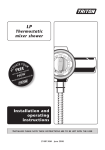
5. ACCESSORIES
When transporting the machine, make sure that the following parts are supplied.
TABLE 5 a ACCESSORIES
DESCRIPTION
Part No. (Qty.)
Note
OWNERS MANUAL
420-6659-01 (1)
KEY MASTER
220-5576 (2)
For opening/closing the doors
Figures
If Part No. has no description, the Number has not been
registered or can not be registered. Such a part may not be
obtainable even if the customer desires to purchase it.
Therefore, ensure that the part is in safekeeping with you.
SERVICE MANUAL NAOMI ENG
420-6455-01 (1)
INSTRUCTION MANUAL FOR THE
GAME BOARD
KEY (2)
For the CASHBOX DOOR
The Keys are inside the Coin
Chute Door at the time of shipment
from the factory.
VOL CONT B-5K OHM
220-5373
(2)
220-5484
Spare, see Section 12.
SEAL TAPE
090-0037 (1)
Used for the maintenance of Air Drive,
for air leakage prevention.
Remote Controller used for
adjustment of the projector.
See Section 14.
200-5536(1)
AIR CLEANER
601-8188 (2)
The Remote Controller is attached to
the Projector at the time of shipment.
For spare, refer to Section 10.
TEST
MODE
WRITING
R
G
B
POSITION
ADJUST
P
SET
PIC-ADJ
RESET
SELECT
11
www.seuservice.com
FUSE 7A
514-5036-7000 (1)
Spare, see Section 17.
www.seuservice.com
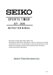
CARTON BOX
601-10532 (1)
Used for transporting the GameBoard.
See FIG 5.
12
HOW TO USE THE CARTON BOX
When requesting for the replacement/repair of this product's Game Board
(NAOMI BOARD), follow the instructions below. Transporting the Game Board
in an undesignated status is unacceptable. An erroneous handling can cause parts
damage.
• Put the Game Board in the Carton Box together with the Shield Case. Do not
unnecessarily disassemble nor remove parts.
• By paying careful attention to the following Figure and the direction shown
by on-Carton-Box printing, put the Shield Case in the Carton Box.
• When putting the Shield Case in the Carton Box, do not remove Leg Brackets.
• The projected portions of the packing material is intended for cushioning.
Therefore, do not bend the projected portions.
"CHECK SIDE" Display
@
Serial No. Display
B
A
FILTER BOARD
Projected portions of
the packing material.
Serial No. Display
FIG. 5
Bend the packing material in numerical order, and wrap the Shield Case with the packing
material and put it in the Carton Box as shown. Putting it upside down or packing otherwise in
the manner not shown can damage the Game Board and the parts.
13
www.seuservice.com
The following Table 5b lists the parts that had been separately packed when the product was
shipped from the factory but are necessary when you use the product. These parts will be
mounted on the product when installing and assembling it.
TABLE 5 b
123
AC Cable (Power Cord)
600-6729
(1) <For TAIWAN>
600-7228
600-6695 (1) <For USA>
600-6619 (1) <AC 220V HONG KONG>
600-6618 (1) <AC 220 ~ 240V AREA>
Used for installation,
see 5 of Section 6.
WIRE HARN EARTH W/LUG
M6
600-6664-02 (1)
<For TAIWAN>
Used for installation,
see 5 of Section 6.
CORD CLAMP
280-5009-01 (1)
Used for installation,
see 5 of Section 6.
The following Table 5c lists the parts that are necessary when setting for the communication
play. Flex Tube, Connector 29 and Fiber Plate had been assembled when the product was
shipped from the factory. (See Section 20.)
TABLE 5 c
FLEX TUBE
310-5285-290100 (1)
Assembled Flex Tube
FIBER PLATE
WRG-0502 (2)
www.seuservice.com
CONN 29
310-5286-29 (2)
14
ASSY FIBER CABLE
600-6275-0700 (2)
NUMBER STICKER
WRG-0003 (1)
1 set of every two sheet sticker, the number 2, 3 and 4.
15
www.seuservice.com
6. ASSEMBLING AND INSTALLATION
Perform assembly work by following the procedure herein stated. Failing to
comply with the instructions can cause electric shock hazard.
Perform assembling as per this manual. Since this is a complex machine,
erroneous assembling can cause an electric shock, machine damage and or not
functioning as per specified performance.
When assembling, be sure to use plural persons. Depending on the assembly
work, there are some cases in which working by one person alone can cause
personal injury or parts damage.
Ensure that connectors are accurately connected. Incomplete connections can
cause electric shock hazard.
Be careful so as not to damage wirings. Damaged wiring can cause electric
shock and short circuit hazards.
Do not carelessly push the PTV. Pushing the PTV carelessly can cause the
PTV to fall down.
This work should be performed by the Location's Maintenance Man or
Serviceman. Performing work by non-technical personnel can cause a severe
accident such as electric shock. Failing to comply with this instruction can
cause a severe accident such as electric shock to the player during operation.
Provide sufficient space so that assembling can be performed. Performing
work in places with narrow space or low ceiling may cause an accident and
assembly work to be difficult.
To perform work safely and avoid serious accident such as the cabinet's
falling down, do not perform work in places where step-like grade
differences, a ditch, or slope exist.
To perform work safely and securely, be sure to prepare a step which is in a
secure and stable condition. Performing work without using the step can cause
violent falling down accidents.
When carrying out the assembling and installation, follow the following 7-item sequence.
1
2
3
4
5
6
7
www.seuservice.com
ASSEMBLING THE PTV
WIRING CONNECTIONS BETWEEN THE CABINETS
SECURING IN PLACE (ADJUSTER ADJUSTMENT)
REMOVING THE SHIPPING BRACKET
POWER SUPPLY, AND EARTH CONNECTION
TURNING POWER ON
ASSEMBLY CHECK
16
Tools required for the work
KEY MASTER
Phillips type screwdriver (for M4, M5 screw)
24mm
WRENCH (for M16 hexagon bolt)
Box nut screwdriver (for M4 hexagon nut) or WRENCH
1
ASSEMBLING THE PTV
1 Fix the two mask holders onto the PTV top panel each with the 2 countersunk-head screws.
2 Insert the TV mask from the underside as illustrated below, and secure with a total of 6 screws.
3 Fix two PTV holders onto the PTV front side each with the 2 screws.
COUNTERSUNK-HEAD SCREW (2 each)
M4 X 12
PTV
MASK HOLDER
MASK
TRUSS SCREW (2)
M5 X 25,flat washer used.
FIG. 6. 1 a
SCREW (4)
M5 X 20,
w/flat & spring washers
PTV HOLDER
SCREW (2 each)
M5 X 16,w/flat & spring washers
17
www.seuservice.com
4 Mount the PTV onto the Front Cabinet.
When performing this work, be sure to
use 4 or more persons.
FIG. 6. 1 b
5 Fix between the PTV and the Front Cabinet on the Cabinet's both sides with 2 screws for each.
6 While supporting the Billboard by 2 persons, another person using a step is to connect the
Billboard wire connector into the terminal board of the PTV top panel.
SCREW (2)
M5 X 16,w/flat & spring washers
BILLBOARD
Connect the Connector.
FIG. 6. 1 d
TRUSS SCREW (2 each)
M5 X 30,flat washer used.
When performing this work, be sure to use 2 or
more persons and be sure to use a step.
www.seuservice.com
18
FIG. 6. 1 c
7 Insert the Billboard into the holder
bracket, fix to PTV with the 2
screws.
8 Remove the 2 truss screws;
dismount the lower lid form the
Front Cabinet's face side.
TRUSS SCREW (black)
M4 X 25
LOWER LID
PHOTO 6. 1 a
9 Connect two wire-connectors inside the Front Cabinet into the PTV connector panel. The
connection angle is fixed. Easy to fix them arranging the angle and the orientation of each
connector. Be sure of the correct connection in order to prevent the damage of the connector or
the terminal portion. There are fixed screws both sides of the Video signal (D-sub) connector.
Fasten them securely.
Connect the Connector.
PHOTO 6. 1 b
19
www.seuservice.com
2
WIRING CONNECTIONS BETWEEN THE CABINETS
Perform the cabinet-to-cabinet wiring. With the ASSY Wire Tube, which installed to the Rear
Cabinet at the time of shipment, connect between the Front Cabinet and the Rear Cabinet.
1 Remove the fixed 4 truss screws
and remove the front cabinet side
Tube Bracket of the ASSY Wire
Tube from the Rear Cabinet.
2 Reinstall the removed 4 truss
screws into the Rear Cabinet.
TRUSS SCREW (4),black
M4 X 12
PHOTO 6. 2 a
3 There are one earth wire and a total of seven wire connectors in the front cabinet side of the
ASSY Wire Tube. Connect the earth wire to the earth terminal stud on the Connector Panel of
the Front Cabinet. Fasten with the hexagon nut in the order of the round earth terminal, the flat
washer and the spring washer.
4 Connect the seven wire connectors to each terminal on the Connector Panel of the Front
Cabinet.
HEXAGON NUT
M4,flat & spring washers used.
PHOTO 6. 2 b
www.seuservice.com
20
5 Install the Tube Bracket to the Front Cabinet, and fix it with the 4 truss screws by using care so
as not to damage the wiring.
TRUSS SCREW (4),black
M5 X 20
PHOTO 6. 2 c
21
www.seuservice.com
3
SECURING IN PLACE (ADJUSTER ADJUSTMENT)
Make sure that all of the adjusters are in contact with the floor. If they are not, the
cabinet can move and cause an accident.
This product has 8 casters (4 for FRONT CABINET, 4 for REAR CABINET) and 8 Adjusters
(4 for FRONT CABINET, 4 for REAR CABINET). (FIG. 6. 3a) When the installation position
is determined, cause the adjusters to come into contact with the floor directly, make adjustments
in a manner so that the casters will be raised approximately 5mm from the floor and make sure
that the machine position is level.
CASTER
1 Transport the product to the
installation position. Be sure to
provide adequate space allowing
the player to get on and off.
2 Have all of the Adjusters make
contact with the floor. Adjust the
Adjuster's height by using a
wrench so that the machine
position is kept level.
3 After making adjustment, fasten
the Adjuster Nut upward and
secure the height of Adjuster
(FIG. 6. 3 b).
ADJUSTER
FIG. 6. 3 a BOTTOM VIEW
ADJUSTER
CASTER
FASTEN UPWARD.
Approx.5mm
ADJUSTER
FIG. 6. 3 b ADJUSTER
10cm
15cm
FIG. 6. 3 c
FIG. 6. 3 d
Refer to this Fig. (Scale:1/100) for
the layout of the place of installation.
Be sure to provide space as shown between the Air
Vent and the wall surface.
www.seuservice.com
22
4
REMOVING THE SHIPPING BRACKET
Before turning the power on, be sure to remove the Sipping Brackets. Turning
power on without removing the Sipping Brackets may cause the parts
damage.
Keep the Sipping Brackets carefully. Removing the product without the
Sipping Brackets can cause parts damage.
At the time of shipment, the Shipping Brackets are secured to rear both sides of the Ride. By
taking out 2 screws from each bracket, remove the Shipping Brackets. Reinstall the removing
screws as before.
SHIPPING BRACKET L (OPPOSITE SIDE: R)
TRUSS SCREW (1)
M4 X 8
TRUSS SCREW (1)
M4 X 12
PHOTO 6. 4
23
www.seuservice.com
5
POWER SUPPLY, AND EARTH CONNECTION
Be sure to independently use the power supply socket outlet equipped with an
Earth Leakage Breaker. Using a power supply without an Earth Leakage
Breaker can cause a fire when electric leakage occurs.
Ensure that the "accurately grounded indoor earth terminal" and the earth wire
cable are available (except in the case where a power cord plug with earth is
used). This product is equipped with the earth terminal. Connect the earth
terminal and the indoor earth terminal with the prepared cable. If the
grounding work is not performed appropriately, customers can be subjected to
an electric shock, and the product's functioning may not be stable.
Ensure that the power cord and earth wire are not exposed on the surface
(passage, etc.). If exposed, they can be caught and are susceptible to damage.
If damaged, the cord and wire can cause electric shock and short circuit
accidents. Ensure that the wiring position is not in the customer's passage
way or the wiring has protective covering.
After wiring power cord on the floor, be sure to protect the power cord.
Exposed power cord is susceptible to damage and causes an electric shock
accident.
The AC Unit is mounted on the right side of the machine. The AC Unit has Main SW, Circuit
Protector, Earth Terminal and the Inlet which connects the Power Cord.
1 Ensure that the Main SW is OFF.
MAIN SW
CIRCUIT PROTECTOR
Main SW off
INLET
EARTH TERMINAL
Connect with the
indoor earth terminal.
AC Cable (Power Cord)
FIG. 6. 5 a AC UNIT
www.seuservice.com
24
2 Connect one end of the earth wire to the AC Unit
earth terminal, and the other end to the indoor earth
terminal. The AC Unit earth terminal has a Bolt and
Nut combination. Take off the Nut, pass the end of
earth wire through the Bolt, and fasten the Nut.
Connect the Earth Wire
to the Earth Terminal.
3 Note that the Earth Wire is incorporated in the Power
Cord for the Areas of AC 120V (USA) and AC 220 ~
240V, and therefore, this procedure is not necessary.
FIG. 6. 5 b Earth Wire Connection
4 Firmly insert the power plug into the
socket outlet.
Insert the opposite side of Power Cord
plug to the AC Unit's connector
("INLET").
5 Perform wiring for the Power Cord
and Earth Wire. Install protective
covering for the Power Cord and
Earth Wire.
Wiring Cover
FIG. 6. 5 c Connecting Power Cord and Earth Wire
In case the Power Plug is apt to come out of place, secure the
Power Cord to the periphery of the AC Unit with the Cord
Clamp (an accessory).
HOW TO USE THE CORD CLAMP
25
www.seuservice.com
6
TURNING POWER ON
When the power is turned on, the ride portion moves. To prevent injury, first
check for safety in the periphery of the ride and then turn power on.
If ERROR is displayed in the ADVERTISE mode, do not operate the
machine. Operating the machine when ERROR is displayed can cause
serious hazard.
During initialization settings, do not touch the ride portion. Wait until the
initialization settings are automatically finished. Touching the ride portion during
setting can cause inaccurate settings and unsatisfactory functioning during game
play.
Turn the AC Unit Main SW ON to turn on the machine's power supply. At the same time the
power is turned on for the power supply, the machine starts the initialization setting movements
and displays the screen on which the setting is being made. Do not touch the Ride until the
initialization setting movements are automatically finished.
1 Approximately 5 seconds after the power is turned on, the compressor starts to operate. If the
pressure inside the tank is insufficient, it takes several minutes to attain the preset pressure. At
the time of installation assembly, it takes approximately 3 minutes. When operation is being
continued, it takes approximately one and half minutes due to the prestress.
2 The ride portion secures the left/right inclination to the center.
3 The front of the ride portion
lowers.
4 The front of the ride portion is
raised.
5 The front of the ride portion
moves to the intermediate
position in the up/down
movement.
6 The front of the ride portion
lowers.
7 The compressor stops.
FIG. 6. 6
After finishing the initialization
setting movements, the ADVERTISE mode returns. During the setting movements, if any
irregularity, malfunctioning, etc. of the moving mechanism are found, ERROR display is shown
on the lower part of the ADVERTISE mode screen. In this case, the machine will not operate
satisfactorily. Please contact the Distributor, etc. where this product was purchased from.
In the case where several machines are connected, network check is performed after
initialization settings are finished, and the screen displays to the effect that the check is being
conducted. After checking, the ADVERTISE mode returns. Normally the network checking
takes 1 ~ 3 minutes. If there is any irregularity in the communication connection, check screen
display will continue.
www.seuservice.com
26
7
ASSEMBLY CHECK
In the TEST MODE, ascertain that the assembly has been made correctly and IC BD is
satisfactory (refer to Section 9).
In the test mode, perform the following test:
( 1 ) MEMORY TEST
Selecting the RAM TEST in the test mode
menu causes the on-board memory to be tested
automatically. The game board is satisfactory if
the display beside each IC No. shows GOOD.
RAM TEST
IC29
IC35
IC09
IC11
IC16
IC20
IC17
IC21
GOOD
GOOD
GOOD
GOOD
GOOD
GOOD
GOOD
GOOD
IC10
IC12
IC18
IC22
IC19
IC23
GOOD
GOOD
GOOD
GOOD
GOOD
GOOD
PRESS TEST BUTTON TO EXIT
( 2 ) C.R.T. TEST
C.R.T. TEST 1/2
1
32
RED
GREEN
BLUE
WHITE
In the test mode menu, selecting C.R.T. TEST allows the
screen (on which the projector is tested) to be displayed.
Although the projector adjustments have been made at the
time of shipment from the factory, color deviation, etc., may
occur due to the effect caused by geomagnetism, the location
building's steel frames and other game machines in the
periphery. By watching the test mode screen, make
judgment as to whether an adjustment is needed. If it is
necessary, adjust the projector by referring to Section 14.
PRESS TEST BUTTON TO CONTINUE
12345678901234567890123
12345678901234567890123
C.R.T. TEST 2/2
12345678901234567890123
12345678901234567890123
12345678901234567890123
12345678901234567890123
12345678901234567890123
12345678901234567890123
12345678901234567890123
12345678901234567890123
12345678901234567890123
12345678901234567890123
12345678901234567890123
12345678901234567890123
12345678901234567890123
12345678901234567890123
12345678901234567890123
12345678901234567890123
PRESS TEST BUTTON TO EXIT
12345678901234567890123
27
www.seuservice.com
( 3 ) SOUND TEST
In the test mode, selecting SOUND TEST
causes the screen (on which sound related BD
and wiring connections are tested) to be
displayed.
Be sure to check if the sound is satisfactorily
emitted from each speaker and the sound
volume is appropriate.
SOUND TEST
RIGHT SPEAKER
LEFT SPEAKER
-> EXIT
OFF
OFF
SELECT WITH SERVICE BUTTON
AND
PRESS TEST BUTTON
( 4 ) INPUT TEST
INPUT TEST
HANDLE BAR
ROLL
THROTTLE LEVER
PITCH
0H
0H
FFH
0H
START
VIEW
SAFETY SENSOR
SERVICE
TEST
OFF
OFF
OFF
OFF
OFF
Selecting the INPUT TEST on the test mode
menu screen causes the screen (on which each
switch and V. R. are tested) to be displayed.
Press each switch. If the display beside each
switch indicates "ON," the switch and wiring
connections are satisfactory.
Check the display of each V.R. value. If the V.
R. is malfunctioning, refer to Sections 11 & 12.
PRESS TEST AND SERVICE BUTTON TO EXIT
( 5 ) OUTPUT TEST
OUTPUT TEST
> START LAMP
VIEW LAMP
EXIT
In the output test mode, carry out lamp test to
ascertain that each lamp lights up satisfactorily.
OFF
OFF
SELECT WITH SERVICE BUTTON
AND PRESS TEST BUTTON
Perform the above inspections also at the time of monthly inspection.
www.seuservice.com
28
7. PRECAUTIONS TO BE HEEDED WHEN MOVING THE MACHINE
When moving the machine, be sure to pull out the plug from the power
supply. Moving the machine with the plug as is inserted can cause the power
cord to be damaged, resulting in a fire and or electric shock.
When moving the machine on the floor, retract the Adjusters and ensure that
Casters make contact with the floor. During transportation, pay careful
attention so that Casters do not tread power cords and earth wires. Damaging
the power cords can cause an electric shock and or short circuit.
In places where step-like grade differences exist, be sure to separate the PTV,
PTV Base, and the Cabinet. Inclining the PTV as is mounted on the PTV
Base can cause the PTV to fall off from the Base and result in injury.
When lifting the cabinet, be sure to hold the catch portions or bottom part.
Lifting the cabinet by holding other portions can damage parts and installation
portions due to the empty weight of the cabinet, and cause personal injury.
When moving the PTV, do not push it from the rear side. Push it from
sideways. Pushing the PTV from the rear side can have the PTV fall down,
causing personal injury etc. In case the floor has slanted surfaces or step-like
differences, be sure to move the machine by 2 or more persons.
Keep the Sipping Brackets carefully. Removing the product without the Sipping
Brackets can cause parts damage.
GRIP PORTION
Do not push PTV from the back. Pushing the PTV
from the back can cause the PTV to fall down. Push
it from the side.
On level surfaces,move the machine by causing
the Casters to make contact with the surfaces.
FIG. 7 a
29
www.seuservice.com
When transporting the product in places with steps
or step-like differences in grade, disassemble into
each unit before transporting.
FIG. 7 b
www.seuservice.com
30
8. CONTENTS OF GAME
The following explanations apply to the case the product is functioning satisfactory. Should
there be any moves different from the following contents, some sort of faults may have
occurred. Immediately look into the cause of the fault and eliminate the cause therefore to
ensure satisfactory operation.
System Behavior in Advertising (Plying-for-Hire) Mode
While the power is connected to the system, the fluorescent light on the billboard is kept on. In
an advertising mode, the system opens an operation explanation screen or a ranking data screen.
The view button flashes when the screen explains how to operate the view button.
Located on the left and right ends of the cabinet, the speakers output audio information. You
may set the ADVERTISE SOUND item to OFF on the GAME ASSIGNMENTS screen so that
this audio output function is disabled in an advertising mode.
The start button flashes when the screen displays the PRESS START BUTTON message. This
PRESS START BUTTON message appears in two cases; when the credit reaches a gamestartable level in an advertising mode and shortly after opening the operation explanation
screen.
Fluorescent lamps are lit.
Image output on the monitor.
Emits sounds.
Throttle Lever
Start Button
Ride
Coin Inlet
Handlebars
View Button (Change the viewpoint)
FIG. 8 a External View of the Cabinet
31
www.seuservice.com
Features of the WaveRunner GP
It provides several marine scenes where a cruising course appearance varies from play to play.
The WaveRunner GP game features:
• Effects of Stern Wave
A stern wave is the wave produced on the wake of a boat. If your boat runs on the stern
waves produced by another boat, it may jump unexpectedly, reduce its speed, or meet any
other navigating difficulty. You must prevent your boat from running on the stern waves and
navigate it with attention to where and how other boats are moving.
• Water-Level-Depending Jumps
A large jump (or a group of small jumps) may appear on the course when a water level is
lower (or higher). The jump that was submerged on your first round cruise may be above the
water on your second round cruise. Therefore, you must navigate your boat differently and/
or change a cruising path, from cruise to cruise, so that you can use an approaching jump.
How to Play
• Insert the coin(s).
• Make sure that the screen shows the PRESS START BUTTON message and that the start
button flashes, and then climb onto the seat.
• Press the start button, and make sure that the operation explanation screen appears. (See the
note 1 below.)
• Wait until the time is counted down to 0 (zero) on the operation explanation screen or
alternately press the start button to exit the screen. In either case the COURSE SELECT
screen appears.
Highlights a selected
course.
Illustrates a course
layout.
Indicates a limit
time for a course
selection.
Shows an image of the
selected course.
Indicates how to operate
the handlebars and the
throttle lever.
FIG. 8 b
www.seuservice.com
32
• The system provides three courses: NOVICE, INTERMEDIATE, and EXPERT. These are
displayed on the upper part of the screen. The selected course is highlighted. To migrate
from one course to another, turn the handlebars leftwards or rightwards. To decide a course,
squeeze the throttle lever. (See the note 2 below.)
MOTION STOP SWITCH
Grip the throttle lever to
decide a course.
Turn the handlebars left/right
to choose the course.
FIG. 8 c
View button
Start button
• Wait until the time is counted down to 0 (zero) on the screen, and then the game starts. (See
the note 3 below.)
• Make sure that the boat starts to move at this moment.
• The screen shows some information; your ranking position among the players (on its upper
right part), a limit time (upper middle), your lap time, best lap time record, and best total
time record (upper left), a tachometer and a speed meter (bottom right), and a speed-down
gauge (bottom left). The speed-down gauge indicates a reduction of the cruising speed as a
result of your boat running on the stern waves. It is dimmed when your boat is not running
on the stern waves.
Limit Time
Player's Lap Time
Player's Ranking
Position
Best Lap Time Record
Best Total Time Record
Tachometer and
Speed Meter
Speed-Down Gauge
(It is dimmed when your boat
is not running on the stern
waves.)
FIG. 8 d
33
www.seuservice.com
• When your boat runs on the stern waves, the speed-down gauge is undimmed and its triangle
becomes filled with shade. If you keep your boat running on the stern waves, the triangle is
shaded more and more.
When the triangle is fully shaded, a warning message "Get out of the wake!" appears on the
screen. If you make your boat off the stern waves at this moment, the speed-down gauge is
again dimmed. If not, it is initialized to 0 (zero) and becomes filled with shade again.
Initially the gauge is dimmed.
When the boat runs on the stern
waves, the gauge is undimmed
and becomes filled with shade.
When the gauge is fully
shaded, a warning message
appears.
FIG 8 e
• When the game starts, the system starts counting down the limit time. If you successfully pass
a checkpoint on the course within the limit time, the bonus time is added to the remaining time.
If not, the game is over. (See the note 4 below.)
• For any course of NOVICE, INTERMEDIATE, or EXPERT. When you have successfully
cruised around it two times, you reach the goal and the game is over. (See the note 5 below.)
• To navigate the boat while playing the game, use the throttle lever and the handlebars, and tilt
up the boat by shifting your body. To increase a cruising speed, squeeze the throttle lever while
to decrease un-squeeze. To turn the boat leftwards and rightwards, turn the handlebars
leftwards and rightwards respectively. To quickly turn the boat, turn the handlebars and then
tilt up the boat to a turning direction of the handlebars. Note that just tilting up the boat without
turning the handlebars does not enable to turn the boat. Press the view button to toggle a viewpoint between a navigator's point and a rearward point.
• When reaching the goal, you can register your name if your lap time is good. Your registered
name will be on a screen's ranking list in an advertising mode.
NOTES:
1) For an interactive communication play. Insert the one-play worth of coin(s) on the operation
explanation screen and press the start button to enter the race. The system opens the entry
screen where you wait until an opposition will enter the race by also inserting the one-play
worth of coin(s) and pressing the start button. The entry screen closes and the operation
explanation screen opens automatically, when a limit time is counted down to 0 (zero).
2) For an interactive communication play. When every player, after entering the race, has
finished selecting a course, the racing course is decided by majority. In case of a tie, the
course with a lower difficulty level is chosen.
3) Alternately, you can press the start button to decide a course.
4) For an interactive communication play. The bonus time is added to the remaining time when
a leading player passes a checkpoint. The place of a player is indicated as 'place/the number
of players' (e.g. 2/4 for a 4-player race, 1/2 for 2-player race). A player number, as 1P and
2P, is shown above the head of a playing character on the screen.
5) You cannot change the number of rounding cruises.
www.seuservice.com
34
Outline of the Courses
Three cruising courses are provided as below. Note that they are different from each other not
only in the difficulty level but also in the appearance and device.
• Novice Course
This course gives the image of a tropical island against a blue sky where the hot sun grills
white beaches. Generally, this novice course curves very gently.
There are three checkpoints including a starting point.
When your boat approaches a palm tree, the coconuts will fall down on your cruising path.
Three dolphins may appear on the way and accompany your boat.
The key part for reaching the goal is located at the end of the course that is sharply curved
and enclosed with the cliffs.
• Intermediate Course
This course gives the image of a thick rainforest with mysterious remains. Generally, this
intermediate course is a very narrow river with rather many curves.
There are four checkpoints including a starting point.
The highlight of this course is a jump from the 50-meter giant waterfall.
In the mangrove woodlands, tall mangroves block your boat. You must be careful not to let it
hit against them.
Big snakes and giant fishes produce an atmosphere of rainforest.
The key parts for reaching the goal are the curves located short of the giant waterfall, in the
mangrove woodlands, and in the cave at the end of the course. You must navigate your boat
with careful attention to these curved spots.
• Expert Course
This course gives the image of a waterfront where the surrounding skyscrapers are blazing in
the evening darkness. This expert course features several combinations of a straight path and
a sharp curve.
There are four checkpoints including a starting point.
All the scenes (the likes of the Brooklyn Bridge, the Statue of Liberty, and the Broadway
with loud neon signs and large illumination bulletin boards) produce an atmosphere of big
city.
The key part for reaching the goal is the sharp curves located immediately after the straight
paths.
35
www.seuservice.com
9. EXPLANATION OF TEST AND DATA DISPLAY
By operating the switch unit, periodically perform the tests and data check. When installing the
machine initially or collecting cash, or when the machine does not function correctly, perform
checking in accordance with the explanations given in this section.
The following shows tests and modes that should be utilized as applicable.
NAOMI GAME BOARD is used for the product. The system of this game board allows another game to be played by replacing the ROM Board Case mounted on the NAOMI CASE. As
such, the Test Mode of this system consists of the System Test Mode for the system to execute
SELF-TEST, COIN ASSIGNMENTS, etc. used in common for the machines employing the
NAOMI BOARD, and the Game Test Mode for the specific product to execute Input/Output
test for the operation equipment, difficulty setting, etc.
When the 2 or more machines are linked for communication play, be careful to
enter the TEST mode. If one of the machines linked enters the TEST mode, all
others display the NETWORK CHECK screen.
www.seuservice.com
36
TABLE 10 EXPLANATION OF TEST MODE
ITEMS
DESCRIPTION
REFERENCE
SECTIONS
INSTALLATION
OF MACHINE
When the machine is installed, perform the following:
1. Check to see that each setting is as per standard setting made at
the time of shipment.
2. In the INPUT TEST mode, check such input devices as each
SW, V.R., etc.
3. In the OUTPUT TEST mode, check such output devices as
lamps, motors, etc.
4. In the self-test mode, check ICs on the IC Board.
SERVICE MANUAL
9-3d
MEMORY
Choose the board test item in the MENU mode to allow the selftest to be performed. In this test, PROGRAM RAMs, ROMs, and
ICs on the IC Board are checked.
SERVICE MANUAL
PERIODIC
SERVICING
Periodically perform the following:
1. Self-Test
2. Ascertain each setting.
3. In the INPUT TEST mode, test the control device.
4. In the OUTPUT TEST mode, check such output devices as
lamps, motors, etc.
CONTROL
SYSTEM
1. In the INPUT TEST mode, check such input devices as each
SW, V.R., etc.
2. Adjust or replace each SW and VR.
3. If the problem can not be solved yet, check the control's moves.
SERVICE MANUAL
MONITOR
In the MONITOR ADJUSTMENT mode, check to see if the
PROJECTOR adjustment is appropriately made.
SERVICE MANUAL
14
IC BOARD
1. Self-Test
2. In the SOUND TEST mode, check the sound related ROMs.
SERVICE MANUAL
SERVICE MANUAL
DATA CHECK
Check such data as game play time and histogram to adjust the
difficulty level, etc.
SERVICE MANUAL
9-3h
37
9-3b
9-3c
SERVICE MANUAL
SERVICE MANUAL
9-3d, e
9-3b
9-3c
9-3e
11,12
www.seuservice.com
9 - 1 SWITCH UNIT AND COIN METER
Do not touch places other than those specified. Touching places not specified can
cause an electric shock or short circuit accident.
Adjust to the optimum sound volume by considering the environmental
requirements of the installation location.
If the COIN METER and the game board are electrically disconnected, game
play is not possible.
SWITCH UNIT
TEST BUTTON
Open the coin chute door, and the switch unit
shown will appear. The functioning of each
SW is as follows:
SOUND VOLUME
SERVICE BUTTON
FIG. 9. 1 a SWITCH UNIT
TEST BUTTON
:
For the handling of the test button, refer to the following pages.
:
Gives credits without registering on the coin meter.
:
Adjust the Speaker Volume.
(TEST)
SERVICE BUTTON
(SERVICE)
SOUND VOLUME
(SOUND VOLUME)
COIN METER
Open the Cashbox Door with the exclusively used key
and the COIN METER will appear underneath the
Cashbox.
COIN METER
FIG. 9. 1 b COIN METER
www.seuservice.com
38
9 - 2 SYSTEM TEST MODE
The contents of settings changed in the TEST mode are stored when the test
mode is finished from EXIT in the menu mode. If the power is turned off
before the TEST mode is finished, the contents of setting change become
ineffective.
Executing "BACKUP DATA CLEAR" in the SYSTEM TEST MODE does
not clear the BOOKKEEPING data in the GAME TEST mode.
Entering the TEST mode clears fractional number of coins less than one credit
and BONUS ADDER data.
Perform setting as per specified in this manual for operation. If setting not
specified is performed for operation, proper function of this product may not
be obtained.
In the SYSTEM TEST MODE, IC BD functioning can be checked, the monitor adjusted, and
the coin setting performed.
Refer to NAOMI SERIVCE MANUAL for the details. Note that the setting of the following
items need to be performed in accordance with the instruction given.
•
•
•
•
CABINET TYPE:
1PLAYER(S)
MONITOR TYPE: HORIZONTAL
SERVICE TYPE:
COMMON
COIN CHUTE TYPE: COMMON
The SEQUENCE SETTING items of COIN ASSIGNMENTS are as follows.
• SEQUENCE SETTING
SEQUENCE 1:
Number of credits required for starting the game.
SEQUENCE 2:
Number of credits required for continuing the play.
SEQUENCE 3 ~ 8: NOT USED
39
www.seuservice.com
9 - 3 GAME TEST MODE
As soon as it enters the Game Test mode, the Ride starts moving. Before entering
the Game Test Mode, be sure to keep away a person(s) from the Ride. Since the
Ride moves momentarily, it may cause accidents.
The new settings will not take effect until the Game Test Mode is exited.
When you make change to the settings, exit the Game Test Mode by proper
operation.
You must not attempt to demonstrate this game (for the selling purpose) with
any other settings other than those specified in this document. Use of such
settings may cause malfunctions or bad operation on the machine.
GAME TEST MENU
By selecting GAME TEST MODE from the System Test Menu Screen, the Game Test Mode
Menu Screen is displayed as follows.
SYSTEM MENU
RAM TEST
JVS TEST
SOUND TEST
C.R.T. TEST
SYSTEM ASSIGNMENTS
COIN ASSIGNMENTS
BOOKKEEPING
BACKUP DATA CLEAR
CLOCK SETTING
GAME TEST MENU
INPUT TEST
OUTPUT TEST
GAME ASSIGNMENTS
VOLUME SETTING
VALVE TEST
WIRING TEST
BOOKKEEPING
BACKUP DATA CLEAR
> EXIT
ROM BOARD TEST
GAME TEST MODE
[*****************]
-> EXIT
SELECT WITH SERVICE BUTTON
AND PRESS TEST BUTTON
SELECT WITH SERVICE BUTTON
AND
PRESS TEST BUTTON
System Test Menu Screen
FIG. 9. 3 a Game Test Menu Screen
• Press the TEST Button to cause the following Test Menu to be displayed on the monitor.
• Press the SERVICE Button until the pointer ">" is moved to the desired item to make a
selection.
• Bring the pointer ">" to the desired item and press the TEST Button to enter the selected
item's test.
• In the Test mode, the Start button instead of Test button and the View button instead of
Service button can be used. These, however, can not be used in the INPUT TEST.
• After the test is complete, move ">" to "EXIT" and press the TEST Button to return to the
System Test Menu Screen.
www.seuservice.com
40
INPUT TEST
When INPUT TEST is selected, the following screen appears on the monitor. The screen
allows the status of each SW and the value of each V.R. of the cabinet to be viewed.
On this screen, periodically check the status of each switch & V.R.
INPUT TEST
HANDLE BAR
ROLL
THROTTLE LEVER
PITCH
0H
0H
FFH
0H
START
VIEW
SAFETY SENSOR
SERVICE
TEST
OFF
OFF
OFF
OFF
OFF
• By pressing each switch, if the display on
the right-hand side of the name of each
switch changes to ON from OFF, the SW
and the wiring connections are satisfactory.
• When checking the SAFETY SENSOR, be
sure to intercept the 3 Sensors on the step.
• Simultaneously pressing the Service button
and the Test button returns the Game Test
Menu screen.
PRESS TEST AND SERVICE BUTTON TO EXIT
FIG. 9. 3 b a INPUT TEST Screen
FIG. 9. 5 b SAFETY SENSOR
LIGHT EMITTER
LIGHT EMITTER
LIGHT RECEIVER
LIGHT EMITTER
LIGHT RECEIVER
LIGHT RECEIVER
The standard values for adjusting each V. R. are as follows:
In this product, the item of VOLUME SETTING allows V. R. values except for PITCH to be
set.
HANDLE BAR:
8 0 H + 9 (centering position)
ROLL:
8 0 H + 9 (centering position)
THROTTLE LEVER: e 0 H + 9 (lever released)
PITCH:
Over 7 0 H (When the Ride is lowered) ~ Under e 0 H (When the Ride is
raised)
41
www.seuservice.com
OUTPUT TEST
The OUTPUT TEST allows the function of each lamp to be checked.
OUTPUT TEST
> START LAMP
VIEW LAMP
EXIT
OFF
OFF
SELECT WITH SERVICE BUTTON
AND PRESS TEST BUTTON
FIG. 9. 3 c OUTPUT TEST Screen
TEST PROCEDURE
1 Press the SERVICE Button to bring the arrow to the lamp item to be tested.
2 Pressing the TEST Button causes "ON" to be displayed and the corresponding lamp lights up.
Pressing the TEST Button again causes "OFF" to be displayed and the lamp goes off.
3 Bring the arrow to EXIT and press the TEST Button to return to the Game Test Menu screen.
www.seuservice.com
42
GAME ASSIGNMENTS
Selecting the GAME ASSIGNMENTS in the menu mode causes the present game setting to be
displayed and also the game setting changes can be made. Each item displays the following
content.
If the COMMUNICATION MODE is set to NO LINK, the items HANDICAP and CABINET
ID will not appear.
GAME ASSIGNMENTS
GAME DIFFICULTY
COMMUNICATION MODE
HANDICAP
CABINET ID
NORMAL
NO LINK
ON
1
> EXIT
SELECT WITH SERVICE BUTTON
AND PRESS TEST BUTTON
FIG. 9. 3 d GAME ASSIGNMENTS Screen
GAME DIFFICULTY: The game difficulty can be differentiated by varying Time at the
time of starting the race and Time at the time of passing the
checkpoint. Choose one from among 3 categories, i.e., EASY,
NORMAL and HARD.
COMMUNICATION MODE: Set up whether the communication (interactive) play is
enabled. There are 3 categories, i.e. MASTER (for one machine/
player only), SLAVE (for communication play), and NO LINK
(not for communication play).
HANDICAP:
In the communication vs. play, this sets whether correction should
be made so that player boat in the second or lower positions
increase the speed. Correction is used with ON and use of
correction is cancelled with OFF.
CABINET ID:
When linked for communication play, allocate the numbers
sequentially in order starting from the leftmost end.
For Communication play, refer to Section 20 "COMMUNICATION PLAY".
SETTING CHANGE PROCEDURE
1 Press the SERVICE Button to bring the arrow (>) to the desired setting change item.
2 Press the TEST Button to choose the desired setting item.
3 Bring the arrow to EXIT and press the TEST Button to return to the Game Test Menu screen.
43
www.seuservice.com
VOLUME SETTING
In this setting item, each V. R. value of the Handlebars, Roll, and Throttle can be set.
Performing settings while riding on the Ride is dangerous as the Ride moves. Use
the Start button instead of Test button, and the View button instead of Service
button.
When V. R. adjustment or replacement has been made, be sure to perform the
setting in that particular V. R. value setting item.
VOLUME SETTING
> HANDLE BAR
ROLL
THROTTLE LEVER
EXIT
SELECT WITH SERVICE BUTTON
AND PRESS TEST BUTTON
FIG. 9. 3 e a VOLUME SETTING Screen
www.seuservice.com
44
(1) HANDLE BAR VOLUME SETTING
HANDLE BAR VOLUME SETTING
MAX
MIN
NEUTRAL
00
00
00
(FF)
(01)
(80)
> EXIT WITHOUT SAVE
EXIT WITH SAVE
SELECT WITH SERVICE BUTTON
AND PRESS TEST BUTTON
FIG. 9. 3 e b HANDLE BAR VOLUME SETTING Screen
SETTING PROCEDURE
1 In the V. R. setting menu screen, press the SERVICE Button to bring the arrow to HANDLE
BAR.
2 Press the TEST Button to cause the HANDLE BAR VOLUME setting screen to appear.
3 Turn the Handlebars fully to the left/right and then release.
4 Press the SERVICE Button to bring the arrow to EXIT WITH SAVE.
5 Press the TEST Button to have the Volume Setting Menu screen return to the screen.
6 When setting other Volume values also, select the applicable select item.
7 Press the SERVICE Button to move the arrow to EXIT and press the TEST Button to return to
the Game Test Menu screen.
45
www.seuservice.com
(2) ROLL VOLUME SETTING
ROLL VOLUME SETTING
MAX
MIN
NEUTRAL
00
00
00
(FF)
(01)
(80)
> EXIT WITHOUT SAVE
EXIT WITH SAVE
SELECT WITH SERVICE BUTTON
AND PRESS TEST BUTTON
FIG. 9. 3 e c ROLL VOLUME SETTING Screen
SETTING PROCEDURE
1 In the Volume Setting Menu mode, press the SERVICE Button to bring the arrow to ROLL.
2 Press the TEST Button to have the ROLL VOLUME setting screen appear on the screen.
3 Incline the Ride fully to the left/right and then cause it to be in the level position.
4 Press the SERVICE Button to bring the arrow to EXIT WITH SAVE.
5 Press the TEST Button to have the Volume Setting Menu return to the screen.
6 When setting other Volume values also, choose the applicable setting item.
7 Press the SERVICE Button to move the arrow to EXIT and press the TEST Button to return to
the Game Test Menu screen.
www.seuservice.com
46
(3) THROTTLE LEVER VOLUME SETTING
THROTTLE LEVER VOLUME SETTING
MAX
MIN
FF
FF
(3B)
(00)
> EXIT WITHOUT SAVE
EXIT WITH SAVE
SELECT WITH SERVICE BUTTON
AND PRESS TEST BUTTON
FIG. 9. 3 e d THROTTLE LEVER VOLUME SETTING Screen
SETTING PROCEDURE
1 In the Volume Setting Menu, press the SERVICE Button and bring the arrow to THROTTLE
LEVER.
2 Press the TEST Button to have the THROTTLE VOLUME SETTING screen appear.
3 Fully grip the Throttle Lever and then release.
4 By pressing the SERVICE Button, bring the arrow to EXIT WITH SAVE.
5 Press the TEST Button to have the Volume Setting Menu return on the screen.
6 When setting other Volume values also, choose the applicable setting item.
7 Press the SERVICE Button to move the arrow to EXIT and press the TEST Button to return to
the Game Test Menu screen.
47
www.seuservice.com
VALVE TEST
This test allows the functioning of each Air Valve, Limit SW and Volume to be checked.
Performing settings while riding on the Ride is dangerous as the Ride moves. Use
the Start button instead of Test button, and the View button instead of Service
button.
VALVE TEST
> PITCH VALVE & ETR CHECK
ROLL VALVE & ETR CHECK
EXIT
PRESS TEST BUTTON TO EXIT
FIG. 9. 3 f a VALVE TEST Screen
FIG. 9. 3 f b VALVE Arrangement
FIG. 9. 3 f c LIMIT SW Arrangement
www.seuservice.com
48
(1) PITCH VALVE & ETR CHECK
PITCH VALVE & ETR CHECK
PITCH VALVE
UP VALVE
ETR UP VALVE
DOWN VALVE
ETR DOWN VALVE
PITCH ETR
UP LIMIT SW
DOWN LIMIT SW
PITCH VOLUME
DOWN
ON
ON
ON
ON
F0H
ON
ON
46H
PRESS TEST BUTTON TO EXIT
FIG. 9. 3 f b PITCH VALVE & ETR CHECK Screen
TEST PROCEDURE
1 In the VALVE TEST MENU, press the SERVICE Button and bring the arrow to PITCH
VALVE & ETR CHECK.
2 Press the TEST Button to have the PITCH VALVE TEST screen appear.
3 Turn the Handlebars to the right to raise the Ride.
4 Turn the Handlebars to the left to lower the Ride.
5 Position the Handlebars in the center to stop the Ride.
6 Gripping the Throttle Lever during 3 ~ 5 above increases the air pressure and releasing
the Throttle Lever decreases the air pressure.
7 During 3 ~ 6 , check the functioning of each Air Valve and Limit SW.
8 Press the TEST Button to return to the VALVE TEST Menu.
9 Choose EXIT and press the TEST Button to return to the Game Test Menu screen.
49
www.seuservice.com
(2) ROLL VALVE & ETR CHECK
ROLL VALVE & ETR CHECK
ROLL VALVE
RIGHT VALVE
LEFT VALVE
ROLL ETR
ROLL VOLUME
ON
ON
ON
F9H
80H
PRESS TEST BUTTON TO EXIT
FIG. 9. 3 f c ROLL VALVE & ETR CHECK Screen
TEST PROCEDURE
1 In the VALVE TEST MENU, press the SERVICE Button and bring the arrow to ROLL
VALVE & ETR CHECK.
2 Press the TEST Button to have the PITCH VALVE TEST screen appear.
3 Turn the Handlebars to the right, and the Ride is subject to the centering force from the right
only.
4 Turn the Handlebars to the left, and the Ride is subject to the centering force from the left only.
5 Position the Handlebars in the center to stop the centering movement.
6 Gripping the Throttle Lever during áBÅ`áD above increases the air pressure and releasing the
Throttle Lever decreases the air pressure.
7 During áBÅ`áE, check the functioning of each Air Valve.
8 Press the TEST Button to return to the VALVE TEST Menu.
9 Choose EXIT and press the TEST Button to return to the Game Test Menu screen.
www.seuservice.com
50
WIRING TEST
Selecting WIRING TEST allows the communication between GAME BD and DRIVE BD to be
checked automatically. If the communication is satisfactorily conducted, "OK" is displayed and
if any irregularity is found, "ERROR" will be displayed.
WIRING TEST
ok
ok
ok
ok
ok
ok
ok
ok
ok
ok
ok
ok
ok
ok
ok
ok
ok
ok
ok
ok
ok
ok
ok
ok
ok
ok
ok
ok
ok
ok
ok
ok
:
:
:
:
:
:
:
:
:
:
:
:
:
:
:
:
:
:
:
:
:
:
:
:
:
:
:
:
:
:
:
:
( f 0 ——>
( f 1 ——>
( f 2 ——>
( f 3 ——>
( f 4 ——>
( f 5 ——>
( f 6 ——>
( f 7 ——>
( f 8 ——>
( f 9 ——>
( f a ——>
( f b ——>
( f c ——>
( f d ——>
( f e ——>
( f f ——>
( 0 f ——>
( 1 f ——>
( 2 f ——>
( 3 f ——>
( 4 f ——>
( 5 f ——>
( 6 f ——>
( 7 f ——>
( 8 f ——>
( 9 f ——>
( a f ——>
( b f ——>
( c f ——>
( d f ——>
( e f ——>
( f f ——>
11111110)
11111101)
11111011)
11110111)
11101111)
11011111)
10111111)
01111111)
10111111)
11011111)
11101111)
11110111)
11111011)
11111101)
11111110)
11111111)
01111111)
10111111)
11011111)
11101111)
11110111)
11111011)
11111101)
11111110)
11111101)
11111011)
11110111)
11101111)
11011111)
10111111)
01111111)
11111111)
PRESS TEST BUTTON TO EXIT
FIG. 9. 3 g WIRING TEST Screen
• After finishing the test, if the above Figure is displayed, it is satisfactory.
• After finishing the test, press the TEST Button to return to the Game Test Menu screen.
51
www.seuservice.com
BOOKKEEPING
Selecting the BOOKKEEPING in the menu mode displays the bookkeeping data up to the
present on the following 12 screens. Press the TEST Button again to proceed to the next page.
When you press the TEST Button during the display of this mode, you return to the Game Test
Menu.
BOOKKEEPING 1/12
NUMBER OF GAMES
PLAY TIME(TOTAL)
PLAY TIME(1P)
PLAY TIME(VS)
AVERAGE PLAY TIME
LONGEST PLAY TIME
SHORTEST PLAY TIME
94
0D
0D
0D
0H
0H
0H
2H 11M 11S
2H 4M 2S
0H 7M 9S
1M 23S
3M 47S
0M 2S
PRESS TEST BUTTON TO CONTINUE
FIG. 9. 3 h a BOOKKEEPING (1/12) Screen
NUMBER OF GAMES:
Number of games played.
TOTAL TIME(TOTAL):
Total energized time.
PLAY TIME(1P):
Total playtime of one player game only.
PLAY TIME(VS):
Total playtime of communication game play.
www.seuservice.com
52
(1) PLAY TIME HISTOGRAM
The time that players have been timeout is displayed in graph. It's a total of 2 screens.
BOOKKEEPING 2/12
PLAY TIME HISTOGRAM 1/2
0M00S
0M10S
0M20S
0M30S
0M40S
0M50S
1M00S
1M10S
1M20S
1M30S
1M40S
1M50S
2M00S
2M10S
2M20S
2M30S
2M40S
2M50S
~
~
~
~
~
~
~
~
~
~
~
~
~
~
~
~
~
~
0M09S
0M19S
0M29S
0M39S
0M49S
0M59S
1M09S
1M19S
1M29S
1M39S
1M49S
1M59S
2M09S
2M19S
2M29S
2M39S
2M49S
2M59S
22
3
1
0
2
1
5
27
1
2
3
2
2
2
3
2
2
0
PRESS TEST BUTTON TO CONTINUE
BOOKKEEPING 3/12
PLAY TIME HISTOGRAM 2/2
3M00S
3M10S
3M20S
3M30S
3M40S
3M50S
4M00S
4M10S
4M20S
4M30S
4M40S
4M50S
OVER
~ 3M09S
~ 3M19S
~ 3M29S
~ 3M39S
~ 3M49S
~ 3M59S
~ 4M09S
~ 4M19S
~ 4M29S
~ 4M39S
~ 4M49S
~ 4M59S
5M00S
4
3
3
3
1
0
0
0
0
0
0
0
0
PRESS TEST BUTTON TO CONTINUE
FIG. 9. 3 h b BOOKKEEPING (2 - 3/12) Screen
53
www.seuservice.com
(2) CLEAR TIME HISTOGRAM
The clear time of the player, which has made a goal, is displayed in graph. Screens are two
screens in NOVICE, INTERMEDIATE and EXPERT, respectively. So it's a total of 6 screens.
BOOKKEEPING 5/12
BOOKKEEPING 4/12
CLEAR TIME HISTOGRAM 2/2
NOVICE
3M00S ~ 3M09S
0
3M10S ~ 3M19S
0
3M20S ~ 3M29S
0
3M30S ~ 3M39S
2
3M40S ~ 3M49S
1
3M50S ~ 3M59S
0
4M00S ~ 4M09S
0
4M10S ~ 4M19S
0
4M20S ~ 4M29S
0
4M30S ~ 4M39S
0
4M40S ~ 4M49S
0
4M50S ~ 4M59S
0
OVER 5M00S
0
CLEAR TIME HISTOGRAM 1/2
NOVICE
0M00S ~ 0M09S
0
0M10S ~ 0M19S
0
0M20S ~ 0M29S
0
0M30S ~ 0M39S
0
0M40S ~ 0M49S
0
0M50S ~ 0M59S
0
1M00S ~ 1M09S
0
1M10S ~ 1M19S
0
1M20S ~ 1M29S
0
1M30S ~ 1M39S
0
1M40S ~ 1M49S
0
1M50S ~ 1M59S
0
2M00S ~ 2M09S
0
2M10S ~ 2M19S
0
2M20S ~ 2M29S
0
2M30S ~ 2M39S
0
2M40S ~ 2M49S
0
2M50S ~ 2M59S
0
PRESS TEST BUTTON TO CONTINUE
PRESS TEST BUTTON TO CONTINUE
BOOKKEEPING 6/12
BOOKKEEPING 7/12
CLEAR TIME HISTOGRAM 1/2
INTERMEDIATE
0M00S ~ 0M09S
0
0M10S ~ 0M19S
0
0M20S ~ 0M29S
0
0M30S ~ 0M39S
0
0M40S ~ 0M49S
0
0M50S ~ 0M59S
0
1M00S ~ 1M09S
0
1M10S ~ 1M19S
0
1M20S ~ 1M29S
0
1M30S ~ 1M39S
0
1M40S ~ 1M49S
0
1M50S ~ 1M59S
0
2M00S ~ 2M09S
0
2M10S ~ 2M19S
0
2M20S ~ 2M29S
0
2M30S ~ 2M39S
0
2M40S ~ 2M49S
0
2M50S ~ 2M59S
0
CLEAR TIME HISTOGRAM 2/2
INTERMEDIATE
3M00S ~ 3M09S
0
3M10S ~ 3M19S
0
3M20S ~ 3M29S
0
3M30S ~ 3M39S
0
3M40S ~ 3M49S
0
3M50S ~ 3M59S
0
4M00S ~ 4M09S
0
4M10S ~ 4M19S
0
4M20S ~ 4M29S
0
4M30S ~ 4M39S
0
4M40S ~ 4M49S
0
4M50S ~ 4M59S
0
OVER 5M00S
0
PRESS TEST BUTTON TO CONTINUE
PRESS TEST BUTTON TO CONTINUE
BOOKKEEPING 8/12
BOOKKEEPING 9/12
CLEAR TIME HISTOGRAM 1/2
EXPERT
0M00S ~ 0M09S
0
0M10S ~ 0M19S
0
0M20S ~ 0M29S
0
0M30S ~ 0M39S
0
0M40S ~ 0M49S
0
0M50S ~ 0M59S
0
1M00S ~ 1M09S
0
1M10S ~ 1M19S
0
1M20S ~ 1M29S
0
1M30S ~ 1M39S
0
1M40S ~ 1M49S
0
1M50S ~ 1M59S
0
2M00S ~ 2M09S
0
2M10S ~ 2M19S
0
2M20S ~ 2M29S
0
2M30S ~ 2M39S
0
2M40S ~ 2M49S
0
2M50S ~ 2M59S
0
CLEAR TIME HISTOGRAM 2/2
EXPERT
3M00S ~ 3M09S
0
3M10S ~ 3M19S
0
3M20S ~ 3M29S
0
3M30S ~ 3M39S
0
3M40S ~ 3M49S
0
3M50S ~ 3M59S
0
4M00S ~ 4M09S
0
4M10S ~ 4M19S
0
4M20S ~ 4M29S
0
4M30S ~ 4M39S
0
4M40S ~ 4M49S
0
4M50S ~ 4M59S
0
OVER 5M00S
0
PRESS TEST BUTTON TO CONTINUE
PRESS TEST BUTTON TO CONTINUE
FIG. 9. 3 h c BOOKKEEPING (4 - 9/12) Screen
www.seuservice.com
54
(3) Detailed data of each course
Allows for checking the detailed data of each course; NOVICE, INTERMEDIATE and
EXPERT. It's a total of 3 screens on each course 1 screen.
2nd line of the screen:
Indicates the course name and the
total playing time.
BOOKKEEPING 10/12
NOVICE
1st
2nd
3rd
4th
5th
6th
7th
CHECK1
CHECK2
CHECK3
CHECK4
CHECK5
CHECK6
68
6
0
0
0
0
0
2
8th
9th
10th
11th
12th
13th
14th
1
2
0
0
1
0
56
17
15
11
8
4
2
AVR.
AVR.
AVR.
AVR.
AVR.
AVR.
43S
37S
36S
27S
34S
36S
PRESS TEST BUTTON TO CONTINUE
1st - 14th:
Indicates the ranking at the play
end time. (It's not whether the
game was cleared or not.)
CHECK 1-6 or 8:
Indicates the number of players,
which arrived at each check-point.
AVR:
Indicates the average time of each
checkpoint section.
BOOKKEEPING 11/12
INTERMEDIATE
15
1st
2nd
3rd
4th
5th
6th
7th
0
0
0
0
0
0
1
8th
9th
10th
11th
12th
13th
14th
CHECK1
CHECK2
CHECK3
CHECK4
CHECK5
CHECK6
CHECK7
CHECK8
9
7
6
5
4
1
0
0
AVR.
AVR.
AVR.
AVR.
AVR.
AVR.
AVR.
AVR.
0
1
1
1
0
1
10
34S
27S
27S
26S
20S
27S
0S
0S
PRESS TEST BUTTON TO CONTINUE
BOOKKEEPING 12/12
EXPERT
1st
2nd
3rd
4th
5th
6th
7th
CHECK1
CHECK2
CHECK3
CHECK4
CHECK5
CHECK6
CHECK7
CHECK8
8
1
0
0
0
0
0
0
8th
9th
10th
11th
12th
13th
14th
5
5
4
4
3
1
0
0
AVR.
AVR.
AVR.
AVR.
AVR.
AVR.
AVR.
AVR.
1
0
0
1
0
0
5
31S
31S
25S
32S
25S
30S
0S
0S
PRESS TEST BUTTON TO EXIT
FIG. 9. 3 h d BOOKKEEPING (10 - 12/12) Screen
55
www.seuservice.com
BACKUP DATA CLEAR
Clears the contents of BOOKKEEPING. When clearing the data, use the SERVICE Button to
bring the arrow to "YES (CLEAR)" and press the TEST Button. When clearing is finished,
"COMPLETED" is displayed. Press the TEST Button again to return to the Game Test Menu
screen. Bring the arrow to "NO (CANCEL)" and press the TEST Button to have the Game Test
Menu screen return on the screen without clearing the data. Note that this operation does not
affect the contents of the game setting.
BACKUP DATA CLEAR
YES(CLEAR)
> NO (CANCEL)
SELECT WITH SERVICE BUTTON
AND PRESS TEST BUTTON
FIG. 9. 3 h c BACKUP DATA CLEAR Screen
www.seuservice.com
56
10. AIR DRIVE
In order to prevent an electric shock and short circuit, be sure to turn power
off before performing work by touching the interior parts of the product.
Be careful so as not to damage wirings. Damaged wiring can cause an
electric shock or short circuit accident.
Do not touch undesignated places. Touching places not designated can cause
electric shock or short circuit.
This work should be performed by the Location's Maintenance Man or
Serviceman. Performing work by non-technical personnel can cause electric
shock hazard.
Do not insert hand into the mechanism so as not to cause hand and fingers
pinched in. Failure to observe this can cause a serious injury such as a
fracture.
When performing work such as parts replacement other than those specified
in this manual, be sure to contact where you purchased the product from and
confirm the work procedures and obtain precautions prior to performing work.
Inappropriate parts replacement and/or installing with erroneous adjustment
can cause an overload or the parts to come into contact, resulting in an electric
shock, a short circuit, and a fire.
Hot compressor can cause burn. After turning power off, wait until hot
portions cool off to start working.
Setting to an undesignated pressure can cause malfunctioning and trouble. Be
sure to use the designated pressure.
Perform dewatering periodically. Gathered water can have compressor load
become greater and cause malfunctioning.
When the set pressure is adjusted, be sure to check if the adjustment is
appropriate.
57
www.seuservice.com
10 - 1 OVERVIEW OF AIR DRIVE SYSTEM
This product uses the compressor. Be sure to turn off the main switch of the AC Unit and start
working after checking that the compressor motor has stopped.
4
1
COMPRESSOR UNIT
TANK UNIT
3
CIRCUIT PROTECTOR
DRIVE BOARD
2
FILTER
REGULATOR
VALVE
CYLINDER
VALVE
CYLINDER
VALVE
CYLINDER
POWER
FIG. 10.1 a Air Drive System Schematic
1 COMPRESSOR UNIT / TANK UNIT
Compresses and stores air by causing the AC Motor to turn the Compressor.
2 FILTER / REGULATOR
Filters foreign matter consisting of fine particles, and water contents in the compression air
(primary side) stored in the COMPRESSOR UNIT and governs the compressed air to a preset
pressure (secondary side). Two Regulators are equipped with: One for high pressure and the
other for low pressure.
3 CIRCUIT PROTECTOR
Protects the AC motor for the compressor from overcurrent.
4 DRIVE BOARD (inside the Front Cabinet)
The DRIVE BOARD controls the entire Air Drive System by activating or stopping the
Compressor depending on the pressure inside the Compressor Unit, and by sending a signal to
open/close each valve in accordance with the progress of game play.
COMPRESSOR
FRONT CYLINDER
VALVE UNIT
REAR CYLINDER
REGULATOR
TANK UNIT
FILTER
FIG. 10.1 b Overview of air drive system
www.seuservice.com
58
10 - 2 DEWATERING FROM THE AIR FILTER
Remove the Rear Lid of the Mechanism Base to have the water tank appear in the inner portion
on the right-hand side. Although the Air Drive Mechanism of the product automatically
dewaters the water from inside the Air Filter, dispose the water from inside the Air Filter by
periodically dewatering (every day in the period of high humidity). Since the oilless
compressor is used for this machine, the drain water can be discharged into a sewer system.
DEWATERING PROCEDURE
1 Turn the main switch of the AC
Unit off.
2 Take out the 5 screws to remove
the Rear Lid of the Mechanism
Base (FIG. 10. 2 a).
TRUSS SCREW (5)
M4 X 12, black
FIG. 10. 2 a
3 The Drain Tube from the Filter is connected to the water tank. Remove the Water Tank from
the Mechanism Base by firmly holding the Drain Tube so as not to allow the tube to come off
from the water tank.
4 When turning and loosening the drain nozzle
underneath the filter in the horizontal
direction, water will gush out together with
the compressed air. Be sure to firmly hold
the Drain Tube so as not to allow the water
can splash out in the periphery
(FIG. 10. 2 b).
Press the Drain Nozzle.
FILTER
DRAIN TUBE
FILTER
SHUT OPEN
Drain Nozzle.
WATER TANK
WATER TANK
SHUT OPEN
WATER TANK
FIG. 10. 2 b
Firmly hold the Tube.
5 The drained water can be discharged into a sewer system.
6 After dewatering is finished, tighten the drain nozzle. Shake the end of the Drain Tube off to
remove water thoroughly, put the tube end into the water tank, and return the water tank to the
Mechanism Base.
59
www.seuservice.com
10 - 3 DEWATERING FROM THE AIR TANK
Water accumulated in the tank increases the load on the Compressor, which may cause
malfunctioning. The Tank should be dewatered at least once a week. Since the oilless
compressor is used for this machine, the drain water can be discharged into a sewer system.
1 Turn the main switch of the AC Unit off.
2 Open the Rear Lid (refer to 10 - 2).
3 The Drain Cock and Drain
Tube are located on this side of
the Air Tank. Pull out the Tube
and insert the end of the Tube
into the Accessory Water Tank
or an appropriate container
(FIG. 10. 3 a).
DRAIN COCK
WATER TANK
FIG. 10. 3 a
4 Turn the Drain Cock by 90
degrees to have the compressed
air and water discharged. If the
cock is not transferred little by
little, water will splash out. At
this time, hold the tube tight so
water may not splash out or on
your body (FIG. 10. 3 b).
Twirl a 90 degrees.
Hold the end of tube tight.
FIG. 10. 3 b
5 After the water is discharged, close the Drain Cock, remove the remaining water from the end of
the air tube and put the tube into the cabinet.
6 The drain water can be discharged into a sewer system.
www.seuservice.com
60
10 - 4 REGULATOR
6.0kgf/cm2
(0.60MPa)
The compressed air (primary
side) in the air tank is governed
to preset pressures by
regulators before the air
pressure is sent to the cylinders.
Check set pressure every 2
months.
Remove Lid Left from the
Mechanism Base (refer to 11-1)
to have the Regulator Unit
appear, and check the pressure
with the Pressure Gauge
attached to each Regulator. If
the pressure within the
Compressor is insufficient, the
Regulator's Pressure Gauge will
not indicate the correct value.
When checking, first turn the
Main SW on and wait until the
Compressor operation stops.
Pressure settings given at the
time of shipment are shown in
FIG. 10. 4.
3.0kgf/cm2
(0.30MPa)
HIGH LOW
PULL DOWN
HIGH LOW
PULL DOWN
FIG. 10. 4
If the actual pressure is different from the set pressure, adjust it as follows:
Before proceeding the work, be sure to turn the Main SW off. However, if the pressure within
the Compressor is insufficient, adjustments can not be performed correctly. First, turn the Main
SW on, and after the Compressor operation stops, turn the SW off, and then proceed the work.
Method of adjustment
1 Pull down the Adjustment Knob of the Regulator until a click is heard.
2 Turn the Adjustment Knob to make adjustment to the preset pressure.
3 When the correct setting is established, push up the adjustment knob until a click is heard.
4 After the setting is finished, play game and check the regulator's pressure gauge once again.
61
www.seuservice.com
10 - 5 AIR CLEANER
The Compressor for this machine is the oilless type and so oil replenishment is not necessary.
However, if the Air Cleaner for protecting the Compressor becomes dirty, the Compressor's
operation efficiency will decrease, and this may cause malfunctioning. Two spare Air Cleaners
are available. Check the Air Cleaners every 2 months.
1 Turn the main switch of the AC
Unit off.
2 Take out the 4 truss screws and
remove the Air Vent on the right
side of the Rear Cabinet.
TRUSS SCREW (4)
M4 X 8,BLACK
PHOTO 10. 5 a
AIR VENT
3 Removing the Air Vent, the
Compressor's Cleaner Cover is
appeared. Taking out the fixed
screws, remove the Cleaner Cover.
CLEANER COVER
PHOTO 10. 5 b
4 Check the Air Cleaner inside the
Compressor. If dirty, replace the
Air Cleaner.
PHOTO 10. 5 c
www.seuservice.com
62
11. MAINTENANCE OF MECHANISM UNIT
In order to prevent an electric shock and short circuit, be sure to turn power
off before performing work by touching the interior parts of the product.
Be careful so as not to damage wirings. Damaged wiring can cause an
electric shock or short circuit accident.
After the power is turned off, close the Main Cock, and then start working.
The Main Cock not closed can cause serious accidents resulting from cylinder
movement, etc., due to some cause.
Periodically retighten the designated bolts. Continuing business operation
with the bolts as is loosened can cause serious accidents.
When assembling, be sure to perform the work by plural persons. Depending
on the assembly work, there are some cases in which performing the work by
a single person can cause personal injury.
Do not touch undesignated places. Touching places not designated can cause
electric shock or short circuit.
This work should be performed by the Location's Maintenance Man or
Serviceman. Performing work by non-technical personnel can cause electric
shock hazard.
Do not insert hand into the mechanism so as not to cause hand and fingers
pinched in. Failure to observe this can cause a serious injury such as a
fracture.
When performing work such as parts replacement other than those specified
in this manual, be sure to contact where you purchased the product from and
confirm the work procedures and obtain precautions prior to performing work.
Inappropriate parts replacement and/or installing with erroneous adjustment
can cause an overload or the parts to come into contact, resulting in an electric
shock, a short circuit, and a fire.
Immediately replace the important parts, which are intended for hazard
prevention, if damaged or omitted. Non- replacement of these parts can cause
accidents.
Hot Compressor can cause burn. After turning the power off, wait until the
high temperature portions cool off to start working.
The mobile parts of this machine need greasing once every 6 months. At the same time,
retighten each installation bolts. Perform the above maintenance work after removing each Lid
and the Bellows Brackets, as per the following procedure.
63
www.seuservice.com
11 - 1 REMOVE THE LID & THE BELLOWS BEFORE SARTING MAINTENANCE WORK
1 Turn the main switch of the AC Unit off.
2 Take out the 5 screws to remove the Rear Lid. (See 10 - 2.)
3 There are 2 Air Cocks inside the Rear Lid. Close the Main Cock on the left side by turning 90
degrees. (Fig. 11.1)
STEP L
Turning 90 degrees
MAIN COCK
STEP R
FIG. 11. 1
4 Take out the 3 truss screws to remove Sash L (L
type fitting). (Photo 11.1a)
TRUSS SCREW (3)
M4 X 12,chrome plated
SASH L
PHOTO 11. 1 a
www.seuservice.com
64
5 Take out the 3 truss screws. (Photo 11.1b)
TRUSS SCREW (3),black
M5 X 12
PHOTO 11. 1 b
6 Remove Step L slowly. Use care when removing the Step L so as not to damage the wiring inside
the Lid. Removing the Step L, the Regulator is appeared. (Photo 11.1c)
7 Pull off the 2 Connectors. (Photo 11.1c)
STEP L
CONNECTOR (2)
PHOTO 11. 1 c
65
www.seuservice.com
8 Take out the 3 truss screws to remove Sash R (L type fitting). (Photo 11.1d)
TRUSS SCREW (3)
M4 X 12,chrome plated
SASH R
PHOTO 11. 1 d
9 Take out the 3 truss screws. (Photo 11.1e)
TRUSS SCREW (3),black
M5 X 12
PHOTO 11. 1 e
www.seuservice.com
66
10 Remove Step R slowly. Use care when removing the Step R so as not to damage the wiring
inside the lid. (Photo 11.1f)
11 Pull out the 2 Connectors. (Photo 11.1g)
STEP R
CONNECTOR (2)
PHOTO 11. 1 f
PHOTO 11. 1 g
12 Take out the 2 truss screws to remove the Bellows Bracket A on both sides ahead of the Ride.
(Photo 11.1h)
TRUSS SCREW (2),black
M5 X 12
PHOTO 11. 1 h
67
www.seuservice.com
13 Take out the 2 truss screws to
remove the Bellows Bracket Front.
(Photo 11.1i)
TRUSS SCREW (2),black
M4 X 12
PHOTO 11. 1 i
www.seuservice.com
68
11 - 2 GREASING AND RETIGHTENING THE BOLTS
Be sure to use the designated grease. Using undesignated grease can cause parts
damage.
Once every 6 months, apply greasing to a ~ f mobile parts. Use Spray Grease
(Part No. 090 - 0025). Apply Spray Greasing to the Rod End and Bearing from the Grease
Nipple. At the same time, check to see if the nuts which secure a ~ f each bearing and
Rod End are loosened. If loosened, retighten the nuts.
FIG. 11. 2
69
www.seuservice.com
d LOWER PART OF LINK & LOWER PART OF REAR CYLINDER
a CRANK PORTION
BEARING (BOTH SIDES)
BEARING
ROD END
ROD END of CYLINDER
b UPPER PART OF LINK
e FRONT CYLINDER PORTION
ROD END
ROD END
c UPPER PART OF REAR CYLINDER
f PITCH VOLUME PORTION
GEAR PORTION
ROD END
www.seuservice.com
70
PHOTO 11. 2
11 - 3 ADJUSTMENT AND REPLACEMENT OF PITCH VOLUME
During game, in the cases where the vertical movements of the Ride is irregular or the Volume
indicates abnormal values, Pitch Volume Gear mesh may be wrong, or Volume malfunctioning
may be the cause. Make adjustments or replace as per the following procedure:
1 Turn the main switch of the AC Unit off.
2 Remove the Rear Lid of the Mechanism Base, and close the Main Cock.
3 Remove the Lid Left of the Mechanism Base. The Pitch Volume can be seen on the side of the
lower front part of the Ride (FIG. 11. 3).
ADJUST GEAR
V.R. SHAFT
V.R. BRACKET
SCREW (2)
M4 X 8, flat & spring washers
V.R.
220-5373,5484
FIG. 11. 3
4 Loosen the 2 screws which secure the V. R. Bracket to move the V. R. Bracket.
5 Move the Volume Bracket to disengage gear mesh, turn the Volume Shaft in the manner so that
the Volume Shaft cut portion faces 45 degrees lower left as shown.
6 Have the gears meshed and tighten the 2 screws to secure the Volume Bracket.
7 When the Volume is malfunctioning, first disconnect the connectors connected to the Volume,
take out the 2 screws which secure the Volume Bracket, and remove the Volume Bracket with
the Volume as is attached.
8 Remove the gear from the Volume Shaft and replace the Volume.
71
www.seuservice.com
11 - 4 REMOVE THE INCLINATION SENSOR
The Inclination Sensor detects the inclination of right and left of the Ride. Malfunctioning the
Ride toward right-and-left direction can cause a failure of the Inclination Sensor. Replace the
Sensor, which located in the bottom behind the Ride, in the following procedure.
1 Turn the main switch of the AC Unit off.
2 Remove the Rear Lid, the Step L and the Step R (see 11 - 1).
3 Pull off the Inclination Senor
Connector.
Disconnect the connector.
PHOTO 11. 4 a
4 Take out the 2 screws and remove
the whole bank bracket of the
Sensor.
SCREW (2)
M4 X 8,w/flat & spring washers
www.seuservice.com
72
PHOTO 11. 4 b
5 Take out the 2 screws and remove
the Sensor from the bracket to
replace it.
INCLINATION SENSOR
370-5130
SCREW (2)
M3 X 8
PHOTO 11. 4 c
6 After the replacement, be sure to perform the Roll Volume Setting in the Test Mode (see 9-3 e).
73
www.seuservice.com
12. HANDLE MECHANISM
Before starting to work, ensure that the Power SW is OFF. Failure to observe
this can cause electric shock or short circuit.
Use care so as not to damage wirings. Damaged wiring can cause electric
shock or short circuit.
Do not touch undesignated places. Touching places not designated can cause
electric shock or short circuit.
This work should be performed by the Location's Maintenance Man or
Serviceman. Performing work by non-technical personnel can cause electric
shock hazard.
Do not insert hand into the mechanism so as not to cause hand and fingers
pinched in. Failure to observe this can cause a serious injury such as a
fracture.
When performing work such as parts replacement other than those specified
in this manual, be sure to contact where you purchased the product from and
confirm the work procedures and obtain precautions prior to performing work.
Inappropriate parts replacement and/or installing with erroneous adjustment
can cause an overload or the parts to come into contact, resulting in an electric
shock, a short circuit, and a fire.
Be careful when handling the plastic made parts. Failure to observe this may
cause injury due to damage or fragments resulting from damage.
In the Test mode, if the variations in Volume (V. R.) values of the Handle Bar, etc. can not be
set within the allowable range, Volume installation position (gear mesh) adjustment or Volume
replacement is needed. Once every 3 months, be sure to apply greasing to gear mesh and spring
portions.
12 - 1 ADJUSTING AND REPLACING THE THROTTLE V.R.
This work requires a Phillips
type screwdriver for M4 screws
and a box nut screwdriver for
M4 hexagon nut or a wrench.
TRUSS SCREW (3),black
M4 X 6
1 Take out a total of 3 Truss
Screws to remove ACCEL.
COVER B.
ACCEL. COVER B
PHOTO 12. 1 a
www.seuservice.com
74
2 Take out a total of 4 Truss Screws to
ACCEL. COVER A
remove ACCEL. COVER A.
TRUSS SCREW (4)
M4 X 6
PHOTO 12. 1 b
3 Take out 2 Truss Screws to remove the VR Cover.
TRUSS SCREW (2)
M4 X 8
VR COVER
PHOTO 12. 1 c
4 Loosen the 2 Nuts which secure the Volume Bracket to move the Volume Bracket. (FIG. 12. 1).
VOLUME220-5373 or 220-5484
V.R. BRACKET
HEXAGON NUT
M4
FIG. 12. 1
75
www.seuservice.com
5 Moving the Volume Bracket causes Adjust Gear mesh to be disengaged.
6 Adjust gear mesh and tighten the 2 Nuts.
7 Grip the Throttle Lever and check to ensure that the V. R. value variations are within the
rotatable range of the Volume Shaft.
8 After finishing adjustments, be sure to perform Throttle Volume setting on the Volume Setting
screen in the Test mode (see 9 - 3e).
REPLACING THE THROTTLE VOLUME
1 Turn the power off.
2 Perform the above adjustment procedure 1 ~ 3 .
3 Disconnect the connector connected to the Throttle Volume. (PHOTO 12. 1 d)
THROTTLE VOLUME
220-5373,5484
CONNECTOR (1)
BLACK 3P
PHOTO 12. 1 d
4 Take out the 2 Nuts which secure the Volume Bracket, and remove the Volume Bracket with
the Volume as is attached.
5 Remove the Volume Gear from the Volume Shaft, and replace the Volume by removing from
the Bracket.
6 After the replacement, perform Volume Setting in the Test mode (see 9 - 3e).
www.seuservice.com
76
12 - 2 ADJUSTING OR REPLACING THE HANDLE V.R.
Adjust or replace the Handle Volume in the following procedure.
This work requires a Phillips screwdriver for M5 screws and a short Phillips screwdriver for M4
screws.
1 Take out the 3 fixed truss screws
and remove the cover of one side
so as not to put the power
excessively.
SIDE COVER
TRUSS SCREW (3),black
M5 X 20
PHOTO 12. 2 a
2 Removing the side cover, the Handle Volume is appeared. Perform this work using a short
Phillips screwdriver.
PHOTO 12. 2 b
77
www.seuservice.com
3 Loosen the 2 screws that secure the V.R. Bracket to move the V.R. Bracket.
4 Move the V. R. Bracket to disengage the Adjust Gear mesh and move the V.R. shaft so that the
cut part of the shaft may turn to the opposite side of the Adjuster Gear as shown.
5 Engage the gear and tighten the 2 screws.
6 Carefully turn the Handle Shaft to the left/right and ensure that the V.R. value variations are
within the range of the Volume.
7 After finishing adjustments, be sure to perform the Handlebars Volume Setting in the Test
Mode (see 9-3 e).
V.R. SHAFT
SCREW (2)M4 X 8,w/flat & spring washers
ADJUST GEAR
GEAR
V.R. BRACKET
FIG. 12. 2
V. R. REPLACEMENT
SCREW (2)
M4 X 8,w/flat & spring washers
1 Take out the 2 screws that secure the
Volume Bracket to remove the
Volume Bracket.
2 Remove the Volume Gear from the
V. R. to replace the V.R.
HANDLE V.R.
220-5373,5484
PHOTO 12. 2 c
3 After the replacement, be sure to perform the Handlebars Volume Setting in the Test Mode
(see 9-3 e).
www.seuservice.com
78
12 - 3 GREASING
Be sure to use the designated grease. Using undesignated grease can cause parts
damage.
Once every 3 months, apply greasing to the following portions. For spray grease, use GREASE
MATE (PART No. 090-0066).
Gear mesh portion
PHOTO 12. 3 a
Torsion Spring portion
Gear mesh portion
PHOTO 12. 3 b
79
www.seuservice.com
13. COIN SELECTOR
HANDLING THE COIN JAM
If the coin is not rejected when the REJECT button is pressed, open the coin chute door and
open the selector gate. After removing the jammed coin, put a normal coin in and check to see
that the selector correctly functions.
CLEANING THE COIN SELECTOR
GATE
Remove and clean smears by using a soft
cloth dipped in water or diluted chemical
detergent and then squeezed dry.
Never apply machine oil, etc. to the Coin
Selector.
After cleaning the Coin Selector, insert a
regular coin in the normal working status
and ensure that the Selector correctly
functions.
FIG. 13 a
The coin selector should be cleaned once every 3 months.
When cleaning, follow the procedure below:
1 Turn the power for the machine OFF. Open the
2
3
4
5
6
7
coin chute door.
Remove the coin selector from the coin chute door.
Open the gate and dust off by using a soft brush
(made of wool, etc.).
Remove and clean smears by using a soft cloth
dipped in water or diluted chemical detergent and
then squeezed dry.
Remove the CRADLE.
When removing the retaining ring (E ring), be very
careful so as not to bend the rotary shaft.
Remove stain from the rotary shaft and shaft
receiving portions by wiping off with a soft cloth,
etc.
After wiping off as per above, further apply a dry
cloth, etc. to cause the coin selector to dry
completely.
COIN INSERTION TEST
FIG. 13 b
Insert a coin
while keeping
the Reject Button
pressed
down and check
if it is rejected.
Once every month, when performing the
Coin SW Test, simultaneously check the
following:
Does the Coin Meter count satisfactorily?
COIN METER
Does the coin drop into the Cashbox correctly?
Is the coin rejected when inserted while keeping the
Reject Button pressed down?
www.seuservice.com
CRADLE
80
FIG. 13 c
81
www.seuservice.com
K
L
29
7
5
J
5
C
1
B
2
5
28
17
F
18
D
G
27
E
H
A
M
14
6
12
26
2701 N. KILDARE CHICAGO, IL 60639
1-800-336-6630
WWW.WGEC.COM
ELECTRONICS CORPORATION
WELLS-GARDNER
24
25
11
19
3
16
15
20
8
4
22
21
13
9
23
10
8
4
812-4050-011
2
DESCRIPTION
NUT KEPS #8-32 X 5/16 HEX
891-1116-16
24G
BRACKET, LAMPSIDE
BRACKET, COVERSIDE
BRACKET, HOLD DOWN
892-1002-021
892-1002-10
28
29
MINI DOOR W/DBV C/O
892-1002-01
27
MINI DOOR 2 ENTRIES
891-0614-16
26
SCREW, PAN HEAD
891-0604-16
25
SLEEVE, SNAP-ON
892-1002-11
24M
ELASTIC SNAP NUT
892-1002-09
892-1002-08
24L
CLIP, SNAP-ON
892-1002-07
24K
COVER, PLASTIC
MICROSWITCH, BLACK - MED.
ADJUSTER, COIN
BRACKET, MICROSWITCH
REJECT CUP BASE PLATE
REJECT CUP SIDE PLATE
KEP NUT
24J
891-1125-00
891-1110-00
24H
891-1107-00
891-1106-00
24D
24F
891-1105-01
24C
24E
890-1206-02
24B
SCREW,FLAT HEAD M/S
REJECT FLAP
020X1877-005
23
MICROSWITCH ASSEMBLY
REJECT BEZEL, NYLON
891-1109-16
22
890-1007-00
BUTTON BEZEL, NYLON
891-1312-16
21
24A
SPRING, E/R BUTTON
891-1311-16
20
891-2216-16
LAMP WEDGE BASE 6 VOLT
891-1121-00
19
24
LAMPHOLDER
891-1118-00
E/R BUTTON US $1 COIN RIGHT
18
E/R BUTTON US 4x25c/$1 LEFT
891-1113-011
16
891-1117-00
BASE PLATE ASSEMBLY
891-1113-03
15
17
COVER PLATE
891-1008-107
LOCK SINGLE BIT
14
891-0547-00
METAL CASHBOX
DOUBLE FRAME
891-0100-4016
13
12
11
891-0509-162
ENCLOSURE W/CHUTE
025X3712-001
025X3711-001
9
10
CLAMP UK 5/8" CABINET
891-0514-00
8
KEYHOOK
WASHER INTERNAL TOOTH 3/4"
890-1019-00
6
890-1300-00
SCREW TRILOBULAR
890-1017-00
5
7
CLAMP SCREW
890-1003-00
HINGE SCREW
S-10 US $1 COIN MECH RIGHT
S-7 US 25c COIN MECH LEFT
4
890-1002-00
812-4150-011
3
W.G. PART #
#
1
WGD15-2110-01
OVER/UNDER MINI DOOR
2 ENTRIES WITH BILL
VALIDATOR
BOTTOM DOOR
& SPECIAL ENCLOSURE
www.seuservice.com
82
Tom Happ
Ph: 847-593-6161 ext. 107
[email protected]
Fx: 847-956-2091
Happ Controls, 106 Garlisch Drive, Elk Grove, IL 60007
Visit our website http://www.happcontrols.com
Guardian Hasp
30-2400-200
OPTIONAL DOLLAR BILL ACCEPTOR
THE COIN DOOR ASSEMBLY USED ON WAVERUNNER GP COMES
EQUIPPED TO ACCEPT A DOLLAR BILL ACCEPTOR. ALL NEEDED
WIRING CONNECTIONS ARE CONVIENENTLY LOCATED INSIDE THE
GAME FOR THIS APPLICATION.
THE COIN DOOR CAN ACCCOMMODATE THE FOLLOWING
VALIDATOR(S):
FORWARD-MOST
HOLE POSITION
**42-1155-00
Mars 2000 series
MARS VALIDATOR $1, 2, 5 300 CAP
The frame and cashbox enclosure on this coindoor has been modified to accomodate
a Mars 2000 series upstacker. A 2000 series stacker can be added by simply removing the cut-out plate. This one entry door can be ordered through Happ Controls or
one of Happ Controls authorized distributors. The part number is 40-6000-10EX.
The Mars stacker can be obtained through an autherized Mars distibutor.
Note: Your game may have either Happ Controls Coin Door Assembly or the Wells
Gardner Coin Door Assembly (not shown).
**Happ part number
Security Locking Bar/Bracket Set Part No.# 999-0966
Modified Cash Box (For use when DBA installed)
Part No. # 999-1106
Plastic Cash Box - Full Size Part No. # 999-1177
83
www.seuservice.com
14.
PROJECTOR
Since the Projector has been adjusted at the time of shipment, avoid making
further adjustments without good reason.
The Projector is subject to color deviation due to Convergence deviation caused
by the geomagnetism at the installation location and peripheral magnetic field.
After the installation of machine, and before commencing operation, check for
Convergence deviation and if deviated, make adjustments.
Projector adjustments are stored. Due to distortion or color deviation in the TEST mode, if an
adjustment is necessary, use the Remote Control to make adjustments.
14 - 1 CLEANING THE SCREEN
Since the Projector screen is susceptible to damage, pay careful attention to its
handling. When cleaning, refrain from using water or volatile chemicals.
When the screen surface
becomes dirty with dust,
etc., clean it by using a soft
cloth such as gauze. When
water, and volatile
chemicals such as benzine,
thinner, etc., spill on the
screen surface, it may be
subject to damage, therefore,
do not use them. Also, since
the surfaces are susceptible
to damage, refrain from
rubbing them with a hard
material or using a duster.
FIG. 14. 1
www.seuservice.com
84
14 - 2 ADJUSTMENT OF TOSHIBA PROJECTOR
SETTING THE INTERFACE
In this product, set to INPUT LEVEL: 0.7V and IMPEDANCE: 75Ω. Failure to
observe this can cause CRT membrane to burn or Shutdown device to function
resulting in power off.
The Projector's Connector Panel contains the Interface setting SW.
WINNER
LAMP
COM
AC IN
AC100-120V~
AC100-120V~
IMPEDANCE
RGB IN
HIGH
INPUT LEVEL
75 ¶ @ @0.7V
1~3V
REMOTE CONTROL BUTTONS
When adjusting the Projector, direct the Remote Control's light emitting portion towards the
Projector Screen.
REMOTE CONTROL LIGHT EMITTING PORTION
MODE (mode selection)
TEST
MODE
WRITING
R
G
B
P
TEST (adjust/normal shift)
R. G. B. (color selection)
WRITING (storing the data)
P (automatic color matching)
SET
SET (to decide the selection)
PIC - ADJ (item selection)
POSITION
PIC-ADJ
POSITION (to select the position)
RESET
RESET
ADJUST
SELECT (pattern selection)
ADJUST (adjustment)
SELECT
85
www.seuservice.com
AUTOMATIC COLOR MATCHING
The Projector may be subject to color deviations affected by earth magnetism, the building steel
frames, etc. When the Projector is initially installed or the Projector's installation position is
changed, have the color matching performed automatically.
1 Keep pressing the P button (red) for approximately 3 seconds to have
the ensuing movements performed automatically.
TEST
MODE
WRITING
R
G
B
POSITION
ADJUST
The Projector will shift to the color deviation
correction mode from the game mode, with
the green cross pattern appearing on the
screen.
P
SET
PIC-ADJ
RESET
SELECT
The cross pattern moves up/down and right/
left to start the movement of searching the correct screen position and inclination.
When the green cross pattern movements are finished, similar detection
is performed sequentially in order of red and then blue cross movements. After detecting by green, red and blue cross movements, the
game mode returns with the color deviation status being corrected.
Although very rarely, the TRY AGAIN error display in red may appear. At this time, press the
P button (red) for approximately 3 seconds.
Even after the above operation is repeated, if the error condition still exists, then the display
shifts to PLEASE ADJ. In this case, the auto color matching function can not be used. Contact
the place of contact herein stated or where the product was purchased from.
If the automatic color matching indicates an error, color matching can manually be performed.
Refer to CONVERGENCE ADJUSTMENT (manual color matching).
www.seuservice.com
86
ADJUSTING THE ON-SCREEN CONTRAST
Although the on-screen picture quality has been adjusted at the time of shipment from the
factory, the on-screen contrast can be readjusted if desired. When the Game Board is replaced,
readjustment may be necessary. Changing the CONTRAST causes the light and shade of the
on-screen images to be changed.
1 Press either
or
PIC - ADJ button.
CONTRAST
BRIGHTNESS
H.POSI
V.POSI
H.SIZE
V.SIZE
EXIT
PIC-ADJ
TEST
MODE
WRITING
R
G
B
POSITION
ADJUST
P
SET
The on-screen menu will
have one item in purple and
6 items in white.
PIC-ADJ
RESET
SELECT
Herein,
procedure 2
is skipped.
2 Choose CONTRAST by using either
or
PIC - ADJ button.
PIC-ADJ
SET
CONTRAST
BRIGHTNESS
H.POSI
V.POSI
H.SIZE
V.SIZE
EXIT
Have CONTRAST displayed in purple. Since
CONTRAST is selected
initially, no particular
operation is required in this
case.
3 Press the SET button (to decide selection).
When the selection of the
CONTRAST adjustment
mode is decided, the
adjustment data scale bar
appears on the screen.
CONTRAST
230
. . . . . . . . . . . . . . . . . . . .
4 Make adjustment by using either
or
ADJUST button.
ADJUST
As the Cursor is moved, the
adjustment data value
changes. Make adjustment
so as to obtain the desired
on-screen contrast status.
CONTRAST
156
. . . . . . . . . . . . . . . . . . . .
WRITING
5 Press the WRITING button (for storing and finish).
The WRITING display
appears and the adjustment
data is stored.
WRITING
When discontinuing the adjustment, choose EXIT from the menu at the stage of procedure 2 and press
the SET button.
To continue adjusting other menu items, repeat procedure 2 ~ 4 .
Unless the adjustment data is stored, the data in the adjusted--status will be erased at the time the power
is turned off and the pre-adjustment status will remain when the power is turned on next time.
87
www.seuservice.com
ADJUSTING THE SCREEN BRIGHTNESS
Although the on-screen picture quality has been adjusted at the time of shipment from the
factory, readjustment can be made if desired. When the Game Board is replaced, readjustment
may be necessary. Changing the BRIGHTNESS causes the brightness of the on-screen images
of black portions to be changed.
1 Press either
PIC-ADJ
TEST
MODE
WRITING
R
G
B
POSITION
P
SET
or
CONTRAST
BRIGHTNESS
H.POSI
V.POSI
H.SIZE
V.SIZE
EXIT
PIC - ADJ button.
The on-screen menu will have one
item in purple and 6 items in
white.
PIC-ADJ
2 Choose BRIGHTNESS by using either
ADJUST
or
PIC
- ADJ button.
RESET
PIC-ADJ
SELECT
SET
CONTRAST
BRIGHTNESS
H.POSI
V.POSI
H.SIZE
V.SIZE
EXIT
Have the BRIGHTNESS displayed
in purple.
3 Press the SET button (to decide selection).
When the selection of the
BRIGHTNESS adjustment mode
is decided, the adjustment data
scale bar appears on the screen.
BRIGHTNESS
128
....................
4 Make adjustment by using either
ADJUST
or
ADJUST
button.
As the Cursor is moved, the
adjustment data value changes.
Make adjustment so as to obtain
the desired on-screen brightness
status.
BRIGHTNESS
156
....................
WRITING
5 Press the WRITING button (for storing and finish).
The WRITING display appears
and the adjustment data is stored.
WRITING
When discontinuing the adjustment, choose EXIT from the menu at the stage of procedure 2 and press
the SET button.
To continue adjusting other menu items, repeat procedure 2 ~ 4 .
Unless the adjustment data is stored, the data in the adjusted status will be erased at the time the power
is turned off and the pre-adjustment status will remain when the power is turned on next time.
www.seuservice.com
88
ADJUSTING THE ON-SCREEN DISPLAY POSITION
Although the on-screen display position (H. POSI, V. POSI) has been adjusted at the time of
shipment from the factory, readjustment can be made if desired. When the Game Board is
replaced, readjustments may be necessary.
1 Press either
PIC-ADJ
TEST
MODE
WRITING
R
G
B
POSITION
P
SET
or
CONTRAST
BRIGHTNESS
H.POSI
V.POSI
H.SIZE
V.SIZE
EXIT
PIC - ADJ button.
The on-screen menu will have
one item in purple and 6 items in
white.
PIC-ADJ
2 Choose H. POSI or V. POSI by using either
ADJUST
or
PIC ADJ button.
RESET
PIC-ADJ
SELECT
CONTRAST
BRIGHTNESS
H.POSI
V.POSI
H.SIZE
V.SIZE
EXIT
SET
Have the H. POSI or V. POSI
displayed in purple. The Figure
shows the status in which H.
POSI is selected.
3 Press the SET button (to decide selection).
When the selection of the H.
POSI or V. POSI is decided, the
adjustment data scale bar appears
on the screen.
H.POSI
128
. . . . . . . . . . . . . . . . . . . .
4 Make adjustment by using either
ADJUST
or
ADJUST
button.
When making adjustments
in vertical directions, also
use either
or
ADJUST button.
WRITING
As the Cursor is moved, the
adjustment data value changes.
Make adjustment so as to obtain
the desired on-screen position
status.
H.POSI
156
. . . . . . . . . . . . . . . . . . . .
5 Press the WRITING button (for storing and finish).
The WRITING display appears
and the adjustment data is stored.
WRITING
When discontinuing the adjustment, choose EXIT from the menu at the stage of procedure 2 and press
the SET button.
To continue adjusting other menu items, repeat procedure 2 ~ 4 .
Unless the adjustment data is stored, the data in the adjusted status will be erased at the time the power
is turned off and the pre-adjustment status will remain when the power is turned on next time.
89
www.seuservice.com
ADJUSTING THE SCREEN SIZE
Although the on-screen size (H. SIZE, V. SIZE) has been adjusted at the time of shipment from
the factory, readjustment can be made if desired. When the Game Board is replaced,
readjustments may be necessary.
1 Press either
PIC-ADJ
TEST
MODE
WRITING
R
G
B
POSITION
P
SET
or
CONTRAST
BRIGHTNESS
H.POSI
V.POSI
H.SIZE
V.SIZE
EXIT
PIC - ADJ button.
The on-screen menu will have one
item in purple and 6 items in
white.
PIC-ADJ
2 Choose H. SIZE or V. SIZE by using either
ADJUST
or
PIC - ADJ button.
RESET
PIC-ADJ
SELECT
CONTRAST
BRIGHTNESS
H.POSI
V.POSI
H.SIZE
V.SIZE
EXIT
Have the H. SIZE or V. SIZE
displayed in purple. The Figure
shows the status in which H. SIZE
is selected.
3 Press the SET button (to decide selection).
SET
When the selection of the H. SIZE
or V. SIZE adjustment mode is
decided, the adjustment data scale
bar appears on the screen.
H.SIZE
128
. . . . . . . . . . . . . . . . . . . .
4 Make adjustment by using either
or
ADJUST
button.
ADJUST
When making adjustments
in vertical directions, also
use either
or
button.
WRITING
As the Cursor is moved, the
adjustment data value changes.
Make adjustment so as to obtain
the desired on-screen position
status.
H.SIZE
156
. . . . . . . . . . . . . . . . . . . .
5 Press the WRITING button (for storing and finish).
The WRITING display appears
and the adjustment data is stored.
WRITING
When discontinuing the adjustment, choose EXIT from the menu at the stage of procedure 2 and press
the SET button.
To continue adjusting other menu items, repeat procedure 2 ~ 4 .
Unless the adjustment data is stored, the data in the adjusted status will be erased at the time the power
is turned off and the pre-adjustment status will remain when the power is turned on next time.
www.seuservice.com
90
CONVERGENCE ADJUSTMENT (manual color matching)
To avoid circuitry malfunctioning due to electrical load increase, never utilize
CONVERGENCE ADJUSTMENT (Line Convergence Adjustment in particular)
for adjusting screen size changes.
There is no means to restore the Convergence Adjustment data once stored, to its
original state. To avoid changing the screen size by erroneously using
convergence adjustment, do not perform the green Line Convergence Adjustment.
As such, be sure to perform the adjustment work from this page onward by the
Technical staff and the location's Maintenance Personnel who are well versed in
such adjustment work. In the Static Convergence Adjustments, if satisfactory
adjustments can not be performed, do not make another convergence adjustments
inadvertently. Contact the office herein stated or where the product was
purchased from.
STOP
IMPORTANT!
To avoid making the adjustment work ineffective, do not press the RESET
button during adjustment.
To discontinue adjustment work, keep pressing the TEST button for
approximately 3 seconds at the stage before storing the adjustment data by
pressing the WRITING button.
Should the screen be abnormally disturbed by noise due to static electricity,
etc., turn the power off without storing the adjustment data.
Pressing the
or
PIC - ADJ button
in the Convergence Adjustment mode
status will display the Adjustment
Menu shown right. Do not utilize this
Adjustment Menu as this is the one
applied at the factory.
Adjusting this menu causes the
Customer's adjustment range to be
deviated.
Should the menu shown right be
displayed by mistake, first choose
EXIT by using either
or
PIC ADJ button and then press the SET
button.
91
ADJUST MODE
SUB VSIZE
SUB HSIZE
SUB BRIGHT
EXIT
Adjustment menu used in the factory.
www.seuservice.com
STATIC CONVERGENCE ADJUSTMENT
In the static convergence adjustment, each of red and blue images is comprehensively moved to
and superimposed on the green color. If automatic color matching function is not sufficiently
satisfactory, perform this adjustment. Be sure to perform automatic color matching before
starting the above adjustment.
1 Keep pressing the TEST button for
approximately 3 seconds.
TEST
MODE
WRITING
P
ADJUST MODE
R
G
B
POSITION
SET
PIC-ADJ
DO NOT PUSH THIS.
ADJUST
The screen will change to
ADJUST mode from the Game
mode to cause the green test
pattern to be displayed on the
screen.
2 Press the R button to have the red adjustment
mode.
RESET
ADJUST MODE
SELECT
The red test pattern is added to
the display. The frame color
turns red and this signifies the
red adjustment mode.
3 Make adjustment by using the
When either of 2 ~ 4 COLOR
SELECT buttons (R, B) is pressed, if the
color desired to be adjusted disappears,
press that particular button again. For
example, if the red color needs to be
adjusted again at the stage of 4 , the R
button need to be pressed twice.
ADJUST buttons.
ADJUST MODE
Make adjustment so as to have
red superimposed on green.
When red is superimposed on
green, the color becomes
yellow.
4 Press the B button to have the blue adjustment
mode.
ADJUST MODE
Similarly as in the case of red,
adjust the blue color. When
green, red, and blue are superimposed, the color becomes
white.
5 Press the WRITING button (for storing and finish).
ADJUST MODE
WRITING
www.seuservice.com
92
The WRITING display appears
and the adjustment data is
stored. After the data is stored,
the Game mode returns.
POINT CONVERGENCE ADJUSTMENT
In the POINT CONVERGENCE adjustment, each of red, green and blue images is partially
moved for color matching. The adjustment may be necessary when the Game Board is replaced or
changed, or screen size is changed. Be sure to perform automatic color matching before starting
the adjustment.
1 Keep pressing the TEST button for
approximately 3 seconds.
ADJUST MODE
TEST
MODE
WRITING
R
G
B
2 Press the MODE button twice to have the POINT
P
ADJUSTMENT mode. Note 1
SET
ADJUST MODE
MARKER
POSITION
ADJUST
The screen changes to ADJUST
mode from the Game mode and
displays the green test pattern.
PIC-ADJ
RESET
DO NOT
PRESS.
The crosshatch test pattern appears
and the MARKER indicating the
adjustment point is displayed.
3 Using either R or B button, select the desired color
to be adjusted. Note 2 By using the G button, the
green color can also be selected.
SELECT
ADJUST MODE
The selected color is displayed by
superimposing on green. The
MARKER will be in the color
selected.
4 By using the
ADJUST buttons,
move the MARKER to the position to be adjusted.
Note 1 When the MODE button is repeatedly
pressed, the adjustment modes will
circulate as follows:
ADJUST MODE
STATIC ADJUSTMENT MODE
LINE ADJUSTMENT MODE
The MARKER moves in the
direction of the button's arrow.
However, the movable point is
predetermined.
5 Make adjustment by using the
ADJUST buttons.
POINT ADJUSTMENT MODE
Note 2 When either of the COLOR SELECT
buttons (R, B) is pressed, if the desired
color to be adjusted disappears, press
that particular button again.
Although the direct vicinity of the
MARKER's center moves most
conspicuously, make adjustment
by paying attention to the periphery area also. Shown left is the
magnified MARKER periphery.
6 Press the SELECT button as necessary to
superimpose Game Board images. Note 3
Note 3 By repeatedly pressing the SELECT
button, only the Projector's TEST
pattern screen and the screen
superimposing the Game Board Test
pattern can be alternately displayed.
ADJUST MODE
If the test pattern is not displayed in
the periphery of the screen, adjustments can be made by pressing the
SELECT button to superimpose the
test pattern and the Game Board's
CRT test screen.
7 Press the WRITING button (for storing and finish).
ADJUST MODE
WRITING
93
WRITING is displayed and the
adjustment data is stored. After the
data is stored, the Game Board
screen returns.
www.seuservice.com
LINE CONVERGENCE ADJUSTMENT
In the LINE CONVERGENCE ADJUSTMENT, the adjustment point of the column line (vertical) or row line (horizontal) is comprehensively moved for color matching. It is convenient to
utilize this adjustment when the color of the column line or row line is uniformly deviated.
1 Keep pressing the TEST button for approximately
3 seconds.
TEST
MODE
WRITING
R
G
B
POSITION
ADJUST MODE
P
SET
PIC-ADJ
2 Press the MODE button once to have the POINT
ADJUSTMENT mode. Note 1
DO NOT PUSH.
ADJUST
The screen changes to ADJUST
mode from the Game Board mode
and displays the green test pattern.
ADJUST MODE
RESET
MARKER
SELECT
The crosshatch test pattern appears
and the vertically long MARKER
is shown.
3 Using either R or B button, select the desired color to
be adjusted. Note 2 Although the green color can also
be selected by using the G button, to avoid the screen
size change adjustment, do not choose green.
ADJUST MODE
Note 1 When the MODE button is repeatedly
pressed, the adjustment modes will
circulate as follows:
STATIC ADJUSTMENT MODE
The selected color is displayed by
superimposing on green. The
MARKER will be in the color
selected.
4 By using the
POSITION buttons,
move the MARKER to the position to be adjusted.
LINE ADJUSTMENT MODE
ADJUST MODE
POINT ADJUSTMENT MODE
Note 2 When either of the COLOR SELECT
buttons (R, B) is pressed, if the desired
color to be adjusted disappears, press
that particular button again.
ADJUST MODE
Use the
buttons to select
the column line, and the MARKER
moves in the right/left direction.
However, the movable range is
predetermined.
Use the
buttons to select
the row line and the MARKER
moves in the up/down direction.
However, the movable range is
predetermined.
5 Make adjustment by using the
ADJUST buttons.
ADJUST MODE
The selected column line or row
line (shown left is the column line)
can be moved in the desired up/
down or right/left directions as
applicable.
6 Press the WRITING button (for storing and finish).
ADJUST MODE
WRITING
www.seuservice.com
94
WRITING is displayed and the
adjustment data is stored. After
the data is stored, the Game Board
screen returns.
15. REPLACEMENT OF FLUORESCENT LAMP
When performing the work, be sure to turn power off. Working with power
on can cause an electric shock or short circuit accident.
The Fluorescent Lamp, when it gets hot, can cause burns. Be very careful
when replacing the Fluorescent Lamp.
To perform work safely and securely, be sure to prepare a step which is in a
secure and stable condition. Performing work without using the step can
cause violent falling down accidents.
Be careful when handling the plastic made parts. Failure to observe this may
cause injury due to damage or fragments resulting from damage.
1 Remove the 3 screws which secure the Holder on the upper part of Billboard.
2 Pull out the Holder to the upper side of the Billboard, and replace the fluorescent lamp (32W).
TRUSS HEAD SCREW (3)
M4 X 8, black
BILLBOARD
BILLBOARD HOLDER
FLUORESCENT LAMP 32W: 390-5251-32-01
GLOW LAMP: 390-5638-5P
FIG. 15 a
When performing work,
prepare a step.
FIG. 15 b
95
www.seuservice.com
16. PERIODIC INSPECTION TABLE
The Air Compressor employed in this product drives the Ride during game. The items listed
below require periodic check and maintenance to retain the performance of this machine and to
ensure safe business operation.
Be sure to check once a year to see if Power Cords are damaged, the plug is
securely inserted, dust is accumulated between the Socket Outlet and the
Power Plug, etc. Using the product with dust as is accumulated can cause a
fire or electric shock.
Periodically once a year, request the place of contact herein stated or the
Distributor, etc. where the product was purchased from, as regards the interior
cleaning. Using the product with dust as is accumulated in the interior
without cleaning can cause a fire or accident. Note that cleaning the interior
parts can be performed on a pay-basis.
TABLE 16
ITEMS
DESCRIPTION
PERIOD
CABINET
Check LEG ADJUSTER adjustments.
Daily
AIR DRIVE
SYSTEM
Dewatering of FILTER.
Weekly
10-2
Dewatering from AIR TANK.
Weekly
10-3
Check Regulator's set pressure.
Bi-monthly
10-4
Check AIR CLEANER.
Bi-monthly
10-5
MECHANISM
HANDLE MECHA
3
Check SAFETY SENSOR.
Daily
3
Check BELLOWS.
Daily
3
Greasing for each of Pillow Block and Rod End.
Biannually
11-2
Tightening the Bolts further.
Biannually
11-2
Check VOLUME VALUE.
Monthly
Greasing of GEAR and bearing.
COIN CHUTE
TOWER
REFERENCE
Tri-monthly
9
12
Check COIN SWes.
Monthly
9
Coin insertion test.
Monthly
13
Tri-monthly
13
Cleaning of COIN SELECTOR.
POWER SUPPLY PLUG
Inspection and cleaning
INTERIOR
Cleaning
CABINET
Cleaning
Annually
See above.
As necessary.
CLEANING THE CABINET SURFACES
When the cabinet surfaces are badly soiled, remove stains with a soft cloth dipped in water or
diluted (with water) chemical detergent and squeezed dry. To avoid damaging surface finish, do
not use such solvents as thinner, benzine, etc. other than ethyl alcohol, or abrasives, bleaching
agent and chemical dustcloth.
www.seuservice.com
96
17. TROUBLESHOOTING
17 - 1 TROUBLESHOOTING
In order to prevent electric shock and short circuit, be sure to turn power off
before performing work.
Be careful so as not to damage wirings. Damaged wiring can cause electric
shock or short circuit.
After removing the cause of the functioning of the Circuit Protector, reinstate
the Circuit Protector. Depending on the cause of the functioning, using the
Circuit Protector as is without removing the cause can cause generation of
heat and fire hazard.
In case a problem occurs, first check wiring connector connections.
TABLE 17 a
PROBLEMS
CAUSE
COUNTERMEASURES
The power is not ON.
Firmly insert the plug into the outlet.
Incorrect power source/voltage.
Make sure that the power supply/voltage are correct.
The CIRCUIT PROTECTOR
functioned due to momentary
overcurrent.
After eliminating the cause of overload, have the Circuit
Protector of the AC Unit restored.
(See Section 6 and Next page)
The fuse of the connect board was
blown out due to momentary
overcurrent.
After eliminating the cause of overload, replace the
specified rating fuse (514-5036-7000, FUSE 6.4 ø X 30
7000mA 125V). (PHOTO 17. 1 b)
The color on the PTV
screen is not correct.
Screen adjustment is not
appropriate.
Make adjustment appropriately. (See Section 14)
PTV screen has a color
deviation.
Affected by the periphery, such as
other machines, location building's
steel frames, etc.
Make convergence adjustments. (See Section 14)
When the main SW is
turned ON, the machine
is not activated.
Change installation direction/ position.
Move the other machines which cause the problem.
No PTV screen image.
Connector connection fault.
Check connector connection between the PTV and Cabinet.
(See Section 6)
Sound is not emitted.
Sound volume adjustment is not
correct.
Adjust the SWITCH UNIT's sound adjustment volume
control. (See 9 - 1)
Malfunctioning BD. and Amp.
Perform SOUND TEST. (NAOMI Service Manual)
During game play, the
Compressor does not
operate.
Circuit Protector functioned due to
momentary overload.
After eliminating the cause of overload, have the power
supply Circuit Protector restored. (PHOTO 17. 1 b)
During game, the Ride does
not operate.
Saftety Sensor functioned.
Remove the foreign article.
Air Tank Cock is closed.
Open the Cock. (See 11-1)
Preset pressure is incorrect.
Make pressure adjustment. (See 10-4)
Air leakage.
Check the Air Drive System.
Communication fault between the
Main BD and the I/O BD.
Check in the wiring test. (See 9-3g)
97
www.seuservice.com
TABLE 17 b
PROBLEMS
CAUSE
COUNTERMEASURES
During game, the Ride does
not turn when the
Handlebars are turned.
Deviation of Handle Volume.
Adjust the Volume value in the test mode. (See 9-3e)
Malfunctioning of Handle Volume.
Replace the Volume. (See 12-2)
When gripping the Throttle
Lever, the Ride does not
advance.
Deviation of Throttle Volume.
Adjust Volume values in the Test mode. (See 9-3e)
Malfunctioning of Throttle
Volume.
Replace the Volume. (See 12-1)
Vertical movements of the
Ride during game is weak
and irregular.
Initial setting is wrong.
Turn power off and then turn it back on again to perform
initial setting movement. (See 6 Section 6)
Malfunctioning of Pitch Volume.
Replace Volume. (See 11-3)
Preset pressure is incorrect.
Make pressure adjustment. (See 10-4)
Air leakage.
Check the Air Drive System.
Communication fault between the
I/O BD and Drive BD.
Check in the wiring test. (See 9-3g)
Air Damper adjustment fault.
Air Damper adjustment. (See the end of this Section)
Deviation of Roll Volume.
Adjust Volume values in the Test mode. (See 9-3e)
Preset pressure is incorrect.
Make pressure adjustment. (See 10-4)
Air leakage.
Check the Air Drive System.
Communication fault between I/O
BD and Drive BD.
Check in the wiring test. (See 9-3g)
Malfanctioning of Inclination
Sensor.
Replace the Inclination Sensor. (See 11-4)
Communication cable connection is
incorrect.
Connect the communication cables correctly. (See 20-2)
Communication settings are wrong.
Correct the settings. (See 20-3)
Connector connection fault.
Check connector connections between the Billboard and
PTV. (See Section 6)
Fluorescent lamp need replacement.
Replace the fluorescent lamp. (See Section 15)
Left/right movements of the
Ride is weak and irregular.
Communication play not
possible.
Fluorescent lamp doesn't
light up.
CIRCUIT PROTECTOR
CIRCUIT PROTECTOR
Functions due to the activation of
bimetal. To restore the function,
wait for approximately one minute
or longer until the bimetal cools
off. (Press the Button.)
www.seuservice.com
98
CIRCUIT PROTECTOR and FUSE REPLACEMENT
In case fuse replacements other than those stated in this manual are necessary,
contact where you purchased the product from for inquiries regarding this
matter.
Fuse replacements other than those specified can cause accidents and are
strictly forbidden.
In order to prevent an electric shock, be sure to turn power off and unplug
from the socket outlet before performing work by touching the internal parts
of the product.
Be careful so as not to damage wirings. Damaged wiring can cause electric
shock and short circuit accidents.
Be sure to use fuses meeting specified rating. Using fuses exceeding the
specified rating can cause fire and electric shock accidents.
After eliminating the cause of the blowing of fuse, replace the fuse.
Depending on the cause of fuse blowing, continued use with the fuse as is
blown can cause generation of heat and fire hazard.
Remove the 2 truss screws and dismount
the lower lid from the front cabinet. The
fuse and the circuit protector for the air
drive are installed on the ASSY PWR
SPLY unit inside the front cabinet.
PHOTO 17. 1 a
TRUSS SCREW,black
M4 X 25
LOWER LID
FUSE 7
514-5036-7000
CIRCUIT
PROTECTOR
PHOTO 17. 1 b
99
www.seuservice.com
AIR DAMPER ADJUSTMENT
In this machine, the Cylinders are equipped with air dampers to soften the impact created by the
Ride movements. If the Cylinder's amplitude of vibration or the impact is excessive, adjust the
air dampers in the following procedure.
After turning the power off, close the Main Cock to start working. Starting work
without closing the Main Clock can cause serious injury.
Make adjustments as specified. Adjusting in the manner not specified can cause
malfunctioning and parts damage.
1 Turn off power and turn the Circuit Protector inside the Front Cabinet OFF (see 10-1).
2 Remove the Rear Lid from the Mechanism Base and close the Main Cock (see 11-1).
3 Remove the Step R (see 11-1).
4 Loosen the Lock Nut of the Rear Cylinder's Adjuster fully to the bottom of the Adjuster.
5 Loosen the A, B, C, and D Adjusters by 90 degrees from the fully tightened point.
6 Tighten the lock nut so the adjuster will not rotate.
7 After making adjustments, play the game and check to see that the adjustments made are
correct.
ADJUSTER A
Loosen by
90 degrees.
Loosen
ADJUSTER B
Loosen by
90 degrees.
Tighten
REAR
CYLINDER
After tightening the
Adjuster fully,
reverse it to the
specified position.
ADJUSTER
LOCK NUT
ADJUSTER D
Loosen by
90 degrees.
After reversing the
adjuster to the specified
position, secure the
Adjuster with LOCK NUT.
FIG. 17
www.seuservice.com
ADJUSTER C
Loosen by
90 degrees.
100
17 - 2 ERROR MESSAGE
This work should be performed by the Location's Maintenance Man or
Serviceman. Performing work by non-technical personnel can cause
accidents.
Should any errors other than listed by this manual or by NAOMI Service
Manual occur, contact where the product was purchased from or an office
described in this manual. Failing to comply with this instruction can cause
accidents.
This product displays the error on the screen if the faulty is detected. If an error is displayed, be
sure to take action against it according to the appropriate cause and countermeasures listed
below.
It may be displayed the error other than listed by this manual or by NAOMI Service Manual. In
that case, contact where the product was purchased from or an office described in this manual
without operating it selfishly.
DISPLAY
CAUSE
COUNTERMEASURES
NETWORK ERROR: NO MASTER SITE
No MASTER setting in Communication Mode.
Perform the Communication Mode setting in the Game Assignments. Set one of the machines to MASTER and all others to
SLAVE. (9-3 d) (20-3)
DISPLAY
CAUSE
COUNTERMEASURES
NETWORK ERROR: DUPLICATE MASTER SITE
MASTER setting is duplicated in Communication Mode.
Perform the Communication Mode setting in the Game Assignments. Set one of the machines to MASTER and all others to
SLAVE.
DISPLAY
CAUSE
COUNTERMEASURES
NETWORK ERROR: NO SLAVE SITE
No SLAVE setting in Communication Mode.
Perform the Communication Mode setting in the Game Assignments. Set one of the machines to MASTER and all others to
SLAVE. (9-3 d) (20-3)
DISPLAY
CAUSE
COUNTERMEASURES
NETWORK ERROR: TOO MANY NODES SITE
Too many machines are connected.
Up to 4 machines can be connected to allow to enjoy communication play.
DISPLAY
CAUSE
COUNTERMEASURES
NETWORK ERROR: DUPLICATE CABINET ID
The number of Cabinet ID is duplicated in Communication Mode.
Change the number of Cabinet ID for every seat in the Game Assignments. (9-3 d) (20-3)
DISPLAY
CAUSE
COUNTERMEASURES
DRIVE BD ERROR: E2H
The Ride is not centering with the right value.
Ensure that the Ride is slanted or the connector of ASSY Wire
Tube is connected securely. (Section 6)
101
www.seuservice.com
DISPLAY
CAUSE
COUNTERMEASURES
DRIVE BD ERROR: E3H
The Down Limit Switch is not changed to ON.
Ensure that the Ride is down fully or the connector of ASSY Wire
Tube is connected securely. (Section 6)
DISPLAY
CAUSE
COUNTERMEASURES
DRIVE BD ERROR: E4H
The Up Limit Switch is not changed to ON.
Ensure that the Ride is up fully or the connector of ASSY Wire
Tube is connected securely. (Section 6)
DISPLAY
CAUSE
COUNTERMEASURES
DRIVE BD ERROR: E7H
The pressure of the air tank is not sufficient.
Be sure of the compressor's function or the air leakage.
DISPLAY
CAUSE
COUNTERMEASURES
NO DRIVE BOARD
The connection of the Drive Board is not correct.
Ensure that the connectors inside of the front cabinet are connected
securely.
www.seuservice.com
102
18. GAME BOARD
In order to prevent electric shock and short circuit hazards, be sure to turn
power off before performing work.
Be careful so as not to damage wirings. Damaged wiring can cause fire,
electric shock and short circuit hazards.
Do not expose the Game BD, etc. without a good reason. Failure to observe
this can cause electric shock hazard or malfunctioning.
To perform work safely and securely, be sure to use 2 or more workers.
The electronic parts on the IC Board could be damaged due to human body's static
electricity. Before performing IC Board related work, be sure to discharge
physically accumulated statics by touching grounded metallic surfaces, etc.
Put the Game Board in the Carton Box (an accessory) together with the Shield
Case when requesting for the replacement or repair. Transporting the Game
Board in an undesignated status for replacement/repair is unacceptable.
In this manual, how to remove the Game Board is explained for convenience.
However, this work should be performed by SEGA SERVICEMAN.
18 - 1 REMOVING THE GAME BOARD
The Game Board is installed inside the Front Cabinet.
1 Turn the main switch of the AC Unit off.
2 Push aside the Rear Cabinet
to keep a workspace.
3 Take out the 2 truss screws that
secure the Service Lid on the
upper front part of the Front
Cabinet.
SERVICE LID
TRUSS SCREW (2),black
M4 X 16
PHOTO 18. 1 a
103
www.seuservice.com
4 Unlock the Service Lid and lift it up a little, and
take out the nut securing the earth wire
carefully to remove the Service Lid.
Unlock
PHOTO 18. 1 b
5 Disconnect all the connectors of the NAOMI Game Board installed inside the Cabinet.
6 Take out the 4 screws securing the Game Board to remove it. Taking out the screws, the Game
Board will fall down. Be sure to take out the screws supporting the Board firmly.
SCREW (4)
M4 X 16,w/flat & spring washers
Disconnect the connector.
PHOTO 18. 1 c
www.seuservice.com
104
18 - 2 COMPOSITION OF GAME BOARD
Ensure that the DIP SW setting is performed as designated. Failure to observe
this may cause functioning not suitable for the actual operation, or
malfunctioning.
ASSY CASE NAO WRG USA (840-0064D-01) : USA
ASSY CASE NAO WRG EXP (840-0064D-02) : OTHERS
ASSY CASE NAO WRG KOR (840-0064D-03) : KOREA
ASSY CASE NAO WRG AUS (840-0064D-04) : AUSTRALIA
SCREW (4)
M3 X 50,chrome plated
ROM CASE NAO WRG
840-0064C
ASSY CASE NAO
COMMUNICATION BD
840-0001E
DIP SW
ASSY CASE NAOMI MAIN BD USA:840-0001A-01
ASSY CASE NAOMI MAIN BD EXP:840-0001A-02
ASSY CASE NAOMI MAIN BD KOR:840-0001A-03
ASSY CASE NAOMI MAIN BD AUS:840-0001A-04
FIG. 18. 2 a
DIP SW SETTING
In this product, set all of the DIP SWes to OFF.
FIG. 18. 2 b
105
www.seuservice.com
19. DESIGN RELATED PARTS
For the Warning Display stickers, refer to Section 1.
FIG. 19 a
www.seuservice.com
106
WRG-3036-B
STICKER BOSS COVER
WRG-3605-B
STICKER ACCELERATOR
WRG-3002-G
STICKER WRGP
WRG-3002-F
STICKER RACING
WRG-0003
STICKER NUMBER WRG OPTIONAL
WRG-3002-E
STICKER MECHATRO
WRG-3003-D
STICKER SPONSOR L
WRG-3003-B
STICKER FRONT LINE L
WRG-3001-P
STICKER SIDE LINE L
WRG-3003-C
STICKER SEGA CRI
… ⁄
WRG-3001-U
STICKER YAMAHA LARGE L
WRG-3001-R
STICKER PROTECTOR L
WRG-3038-B
STICKER SIDE GUARD L
WRG-3001-L
STICKER SHARK
… ⁄
WRG-3001-M
STICKER NO.1 L
WRG-3001-V
STICKER YAMAHA LARGE R
WRG-3022
STICKER BASE SIDE L
WRG-3001-Q
STICKER SIDE LINE R
WRG-3004-D
STICKER SPONSOR R
WRG-3004-B
STICKER FRONT LINE R
WRG-3001-S
STICKER PROTECTOR R
WRG-3039-B
STICKER SIDE GUARD R
WRG-3001-N
STICKER NO.1 R
WRG-3023
STICKER BASE SIDE R
FIG. 19 b
107
www.seuservice.com
FIG. 19 c
www.seuservice.com
108
20. COMMUNICATION PLAY
For this game, up to 4 machines can be connected to allow up to 4 players to play
simultaneously. In this instance, connecting the communication cable and setting for the
communication play are required.
20 - 1 INSTALLATION PRECAUTIONS
Before starting to work, ensure that the Power SW is OFF. Failure to observe
this can cause electric shock or short circuit.
Use care so as not to damage wirings. Damaged wiring can cause electric
shock or short circuit.
Do not touch undesignated places. Touching places not designated can cause
electric shock or short circuit.
This work should be performed by the Location's Maintenance Man or
Serviceman. Performing work by non-technical personnel can cause electric
shock hazard.
When linking a number of machines, be sure to supply sufficient power for
the corresponding number of machines. Be sure to secure per machine
current as stated in this manual. Failure to observe this can cause a fire and an
electric shock accident.
Due to the length of the communication cable, the distance in between the
machines is limited. However, to avoid accidents, be sure to secure space in
excess of 70 cm between the machines.
In order to avoid personal injury, when separating the machine into each
Cabinet, pay attention so as not to cause the PTV to fall down.
To perform work safely and avoid serious accident such as the cabinet's
falling down, do not perform work in places where step-like grade
differences, a ditch, or slope exist.
To perform work safely, be sure to secure the space corresponding to number of
machines to be linked. Failure to observe this can cause accident.
The optic fiber cable is used for the communication linkage.
Excessive bending may damage the communication cable. Be very careful in this
regard.
Since 2 or more machines are to be linked, sufficient power corresponding to the number of
machines used need to be supplied. Note that as a standard, the per machine capacity should be
15A for the 100 ~ 120V area, and 8A for the 220 ~ 240V area.
109
www.seuservice.com
70cm
DISTANCE BETWEEN MACHINES
Be sure to secure space in excess of
70cm between machines.
FIG. 20. 1
20 - 2 CONNECTING THE COMMUNICATION CABLE
To enable the game machines to serve in a communication play, you must interconnect their
game boards with the communication cables (optical fiber cables).
For this wiring, prepare the parts described in Table 5c of Section 5 and a short Phillips
screwdriver for M4 screws.
1 Turn off power and disconnect the plug. Disconnect the power cord so as not to damage it.
2 Referring to Section 7, uncouple and align the machines keeping the workspace in front of the
Front Cabinet.
3 Remove the Service Lid on the upper front part of the Front Cabinet (see 18-1).
4 Take out the 2 truss screws and remove the Lower Lid in front of the Front Cabinet.
TRUSS SCREW (4),black
M4 X 16
5 Take out the 4 truss screws and
remove the Side Lid on the side of
the Front Cabinet. In this instance,
remove the Side Lid that lets the
communication cable pass.
Depending on the number and
arrangement of the interconnected
game machines, you may remove
either or both of the two Side Lids.
SIDE LID
PHOTO 20. 2 a
www.seuservice.com
110
6 Insert the communication cable
into the assembled flex tube.
Depending on the number of the
interconnected game machines, the
method of the interconnection
varies.
PHOTO 20. 2 b
7 Connect the communication cable to each game
board. Pass the communication cable through
the round hole on the side of the Front Cabinet
and connect to the game board connectors. A
connecting method varies depending on the
number of the interconnected game machines
(see Fig. 20.2b).
Always connect the red connector to RX and
the black connector to TX, and thereby make a
loop of the communication cable.
Connect the communication cable.
PHOTO 20. 2 c
111
www.seuservice.com
FIBER PLATE
8 Fix the Fiber Plate on the side of
the Front Cabinet using the 4 truss
screws that secured the Side Lid
previously.
TRUSS SCREW (4),black
M4 X 16
PHOTO 20. 2 d
TRUSS SCREW (2),black
M4 X 16
NAOMI BD
COMMUNICATION
CABLE
Unlock
SERVICE LID
FLEX TUBE
TRUSS SCREW (2),black
M4 X 25
LOWER LID
TRUSS SCREW (4),black
M4 X 16
FIG. 20. 2 a
www.seuservice.com
112
2P LINK
3P LINK
4P LINK
FIG. 20. 2 b Connecting method of the communication cable
9 Install the Service Lid on the Front Cabinet and lock it.
10 Arrange the interconnected game machines. Keep a space between the game machines as wide
as possible.
11 Make the adjusters of all the game machines come into contact with the floor
(see Section 6 3 ).
12 Connect the power cords and the earth wires (see Section 6 5 ).
13 Put the number stickers on both
sides of the Ride. Facing the PTV
screens, put the stickers '1', '2', '3',
'4' from left to right.
FIG. 20. 2 c
113
www.seuservice.com
20 - 3 SETTING FOR COMMUNICATION PLAY
Change the game setting for each seat in manner so as to meet communication play. If the
setting is not correct, communication play cannot be played.
SETTING FOR COMMUNICATION PLAY
1 Turn the linked machines' power on.
2 Cause all of the machines to enter the test mode (see Section 9).
3 Select the GAME ASSIGNMENTS (see 9-3 d).
GAME ASSIGNMENTS
GAME DIFFICULTY
COMMUNICATION MODE
HANDICAP
CABINET ID
NORMAL
NO LINK
ON
1
If it is set to SLAVE,
GAME DIFFICULTY and
HANDICAP are
disappeared on the screen.
> EXIT
SELECT WITH SERVICE BUTTON
AND PRESS TEST BUTTON
FIG. 20. 3 GAME ASSIGNMENTS Screen
4 Perform the COMMUNICATION MODE setting in the GAME ASSIGNMENTS screen. Set
one of the machines to MASTER and all others to SLAVE.
5 Perform the CABINET ID setting in the GAME ASSIGNMENTS screen. Set the machines to 1,
2, 3 and 4 sequentially in order starting from the leftmost machine facing the screen. Set every
number correctly without duplicating.
6 Cause all of the machines to exit from the test mode by selecting EXIT in the System Test
Menu.
7 Exiting from the test mode causes the unit to perform the network check automatically. The
Network Check screen appears on the screen.
8 When finishing the network check successfully, the Advertise Screen appears. Normally the
network check finishes within several 10 seconds. If the screen does not proceed from the
Network Check screen, some sorts of errors such as the error of the setup, the error of cable
connection, and malfunctioning the communication cables, etc. can be considered.
www.seuservice.com
114
20 - 4 CAUTIONS TO BE HEEDED DURING COMMUNICATION PLAY
During communication play, if communication is interrupted due to some
cause, the game is discontinued and the Network Check screen is displayed.
If one of the linked machines enters the Test Mode, all others display the
Network Check screen.
Even if it has set to the communication play, you can setup a different charge
for every machine.
A wrong charge setup may cause the problems of income and outgo.
Machine's operation when linked for communication play alters comparing to that of when
independently operated. Be careful of this point.
When any game machine is in a Test Mode, a Network Check screen appears on the other game
machines interconnected for a communication play. While a guest is using any one of the
interconnected game machines, therefore, do not activate a Test Mode even on the unused game
machine.
115
www.seuservice.com
21. PARTS LIST
1 TOP ASSY WRG
2 WRG-0500
ASSY PTV
3 WRG-0510
PTV W/STICKER WRG
4 WRG-0550
ASSY BILLBOARD
5 MGL-1150
ASSY MASK
7 WRG-1001
ASSY SUB CABINET
8 STR-1070
FAN UNIT
10 WRG-1020
ASSY SERVICE LID
9 WRG-6002
ASSY WIRE FRONT DC
11 WRG-1030
ASSY LOWER LID
6 WRG-1000
ASSY FRONT CABINET
16 WRG-3000
ASSY REAR CABINET
12 WRG-4000
ASSY MAIN BD
19 WRG-3101
MECHA BASE
13 WRG-4100
ASSY DRIVE BD
20 MJT-3180
ASSY REGU
14 WRG-4200
ASSY PWR SPLY
21 WRG-3200
ASSY VALVE
15 NCR-1090
AC UNIT
22 MJT-3220
ASSY FRONT CYLINDER
17 WRG-3001
MAIN BODY
23 MJT-3240
ASSY REAR CYLINDER
18 WRG-3100
ASSY MECHA BASE
24 MJT-3380
VR UNIT
26 WRG-3320
ASSY LID L
35 COMPRESSOR &
COMPRESSOR BOX
27 WRG-3340
ASSY LID R
28 WRG-3360
ASSY STEP L
25 WRG-6003
ASSY WIRE BASE DC
29 WRG-3380
ASSY STEP R
8 STR-1070
FAN UNIT
30 WRG-3500
ASSY COINCHUTE TOWER
32 WRG-3600
ASSY HANDLE MECHA
33 MJT-3650
ASSY CENTERING MECHA
34 WRG-6001
ASSY WIRE TUBE
www.seuservice.com
116
31 WRG-3550
SW UNIT
1 TOP ASSY WRG
(D-1/2)
117
www.seuservice.com
1 TOP ASSY WRG
(D-2/2)
ITEM NO.
PART NO.
DESCRIPTION
1
2
3
4
WRG-0500
WRG-1000
WRG-3000
DYN-0011
5
421-7308-~
11
12
13
14
15
16
17
18
19
440-CS0186-EG
440-WS0002XEG
421-8479-01
MJT-0004
MJT-0005
SGM-4357
SGM-4390
WRG-0501
421-11466-01
ASSY PTV
ASSY FRONT CABINET
ASSY REAR CABINET
DENOMI PLATE W/O ORIGINAL
Locally supplied.
DENOMI SH 1GAME ~
Locally supplied.
STICKER C EPILEPSY 40 ENG
STICKER W POWER OFF ENG
STICKER INSTR SUNLIGHT ENG
SHIPPING BRKT L
SHIPPING BRKT R
POLY COVER 1600 X 1300 X 1050
POLY COVER 1150 X 400 X 650
SIDE LID
INSTR SH TRANSPORT WRG ENG
201
202
203
204
000-T00530-0B
068-552016-0B
000-T00520-0B
000-T00408-0C
205
008-T00412-0B
401
402
403
404
405
406
407
409
417
601-6604-70
420-6659-01
420-6455-01
SGM-2675X
220-5576
SGM-4111X
WRG-0003
220-5373
220-5484
514-5036-7000
090-0037
600-6275-0700
310-5285-290100
310-5286-29
WRG-0502
600-7228
600-6729
600-6619
600-6618
600-6695
600-6664-02
418
280-5009-01
CARTON BOX 70
OWNERS MANUAL WRG ENG
SERVICE MANUAL NAOMI ENG
POLYETHYLENE BAG 240 X 370
KEY MASTER FOR 220-5575
KEY BAG
STICKER NUMBER WRG OPTIONAL
VOL CONT B-5K
VOL CONT B-5K OHM
FUSE 6.4 X 30 7000MA 125V
SEAL TAPE
ASSY FIBER CABLE 5 0700CM
FLEX TUBE 29-0100CM
CONN 29
FIBER PLATE
AC CABLE CONNECT TYPE 15A
AC CABLE CONNECT TYPE 15A
AC CABLE CONNECT TYPE FOR UK
AC CABLE CONNECT TYPE FOR EXP
AC CABLE CONNECT TYPE USA 15A
WIRE HARN EARTH W/LUG M6
NOT USED
CORD CLAMP 21
/
/
/
/
/
/
/
/
105-5356
421-8740
421-6690-06
421-6690-01
421-6690-03
421-6690-05
421-6119-91
421-6120-93
SHIPPING BRKT
CAUTION INSTR COP U/R
STICKER 110V
STICKER 120V
STICKER 220V
STICKER 240V
STICKER FCC
STICKER SEGA USA
www.seuservice.com
OTHERS
USA
OTHERS
USA
M SCR TH BLK M5 X 30
FLT WSHR BLK 5.5-20 X 1.6
M SCR TH BLK M5 X 20
M SCR TH CRM M4 X 8
Locally supplied.
TMP PRF SCR TH BLK M4 X 12
Locally supplied.
118
123
OTHERS
USA
OTHERS
USA
TAIWAN
HONG KONG
AC 220 ~ 240V AREA
USA
TAIWAN
OTHERS
AC 110V AREA
AC 120V AREA
AC 220V AREA
AC 240V AREA
123
410
411
412
413
414
415
416
NOTE
USA
2 ASSY PTV (WRG-0500)
ITEM NO.
PART NO.
DESCRIPTION
1
2
3
4
5
WRG-0510
MGL-1150
WRG-0550
HOD-1101
RAL-0501
PTV W/STICKER WRG
ASSY MASK
ASSY BILLBOARD
PTV HOLDER
MASK HOLDER
000-F00412
000-P00516-W
000-P00520-WB
000-T00525-0B
068-552016-0B
M SCR FH M4 X 12
M SCR PH W/FS M5 X 16
M SCR PH W/FS BLK M5 X 20
M SCR TH BLK M5 X 25
FLT WSHR BLK 5.5-20 X 1.6
201
202
203
204
205
119
NOTE
www.seuservice.com
3 PTV W/STICKER WRG (WRG-0510)
ITEM NO.
PART NO.
DESCRIPTION
1
2
WRG-0511
WRG-0512
STICKER PTV SIDE L
STICKER PTV SIDE R
101
200-5788-31
PROJECTION DSPL T 50TYPE 31K
www.seuservice.com
120
NOTE
(D-1/2)
SCREW FASTENING TORQUE
TO BE
M4: 1.8 N•m
4 ASSY BILLBOARD (WRG-0550)
121
www.seuservice.com
4 ASSY BILLBOARD (WRG-0550)
(D-2/2)
ITEM NO.
PART NO.
DESCRIPTION
1
2
3
4
5
6
WRG-0551
WRG-0552
ASK-1224
ASK-1225
WRG-0553
253-5457
7
421-7501-18
8
9
440-WS0002XEG
440-WS0012XEG
LEFT COVER
RIGHT COVER
BILLBOARD BOX
BILLBOARD HOLDER
BILLBOARD PLATE
FL HOLDER
Locally supplied.
STICKER FL32W
Locally supplied.
STICKER W POWER OFF ENG
STICKER W HIGH TEMP ENG
101
390-6659-32EX
102
280-5009-01
201
202
203
000-F00410
000-T00408-0B
000-P00430-S
204
205
068-441616-0B
000-P00408-W
M SCR FH M4 X 10
M SCR TH BLK M4 X 8
M SCR PH W/S M4 X 30
Locally supplied.
FLT WSHR BLK 4.4-16 X 1.6
M SCR PH W/FS M4 X 8
301
WRG-60057
WH FL
www.seuservice.com
ASSY FL32W EX W/CONN HIGH S CE
Locally supplied.
CORD CLAMP 21
122
NOTE
OTHERS
USA
OTHERS
USA
OTHERS
USA
OTHERS
USA
5 ASSY MASK (MGL-1150)
ITEM NO.
PART NO.
DESCRIPTION
1
2
3
MGL-1102
MGL-1151
MGL-1152
TV MASK
SLIT PLATE
MASK SIDE HOLDER
012-F00408-0B
000-F00410
TAP SCR FH BLK 4 X 8
M SCR FH M4 X 10
201
202
123
NOTE
www.seuservice.com
6 ASSY FRONT CABINET (WRG-1000)
www.seuservice.com
124
(D-1/2)
6 ASSY FRONT CABINET (WRG-1000)
ITEM NO.
PART NO.
DESCRIPTION
1
2
3
4
5
6
7
8
9
WRG-1001
WRG-1020
WRG-1030
WRG-4000
WRG-4100
WRG-4200
NCR-1090
WRG-1006
WRG-1007-01
ASSY SUB CABINET
ASSY SERVICE LID
ASSY LOWER LID
ASSY MAIN BD
ASSY DRIVE BD
ASSY PWR SPLY
AC UNIT
STICKER SERVICE LID
PLAY INSTR SH WRG ENG
201
202
203
204
205
206
207
000-P00435-S
000-T00416-0B
068-441616
000-P00408-W
000-P00535-S
068-552016
000-T00425-0B
M SCR PH W/S M4 X 35
M SCR TH BLK M4 X 16
FLT WSHR 4.4-16 X 1.6
M SCR PH W/FS M4 X 8
M SCR PH W/S M5 X 35
FLT WSHR 5.5-20 X 1.6
M SCR TH BLK M4 X 25
125
(D-2/2)
NOTE
www.seuservice.com
(D-1/2)
OPPOSITE SIDE
7 ASSY SUB CABINET (WRG-1001)
www.seuservice.com
126
7 ASSY SUB CABINET (WRG-1001)
ITEM NO.
(D-2/2)
PART NO.
DESCRIPTION
1
2
3
4
5
6
7
8
9
10
11
12
13
14
15
16
17
WRG-1002
STR-1070
FRQ-1009
FRQ-1012
117-5284
HOD-1003
253-5460-01
253-5396-91
WRG-1003
WRG-1004
WRG-1005
WRG-1008
WRG-1009
WRG-1010
WRG-1011
WRG-1012
WRG-1013
WOODEN FRONT CABINET
FAN UNIT
LEG CASTER BRKT A
LEG CASTER BRKT B
PLATE 6-80 BLACK
LOCKING BRKT HOD
AIR VENT BLACK
CABINET HANDLE
SPEAKER BRKT
SPEAKER PLATE
CONNECTOR PNL BRKT CABI
STICKER FRONT CABI L
STICKER FRONT CABI R
STICKER SPEAKER UPPER L
STICKER SPEAKER UPPER R
STICKER SPEAKER LOWER L
STICKER SPEAKER LOWER R
101
102
601-5699X
601-9377
601-6224
280-5009-01
280-0419
601-0460
601-10369
117-5402-06-91
130-5228
560-5459
560-5446-H
LEG ADJUSTER BOLT M16 X 75
CASTER FAI=75
CASTER 75
CORD CLAMP 21
HARNESS LUG
PLASTIC TIE BELT 100 MM
STEREO PWR AMP 47
EARTH TERMINAL PLATE 6P
SPEAKER BOX 4OHM 40W
XFMR 100-120V 100V10A (NM)
XFMR 220-240V 100V 10A CE (NM)
201
202
203
204
205
206
207
208
209
210
211
212
213
214
215
216
217
008-T00416-0B
030-000630-SB
000-P00420-W
050-F00400
000-T00416-0B
050-H01600-0B
030-000616-W
011-F00312
011-T03512
000-P00516-S
000-F00416
012-P00512-0B
000-P00408-W
050-H00400
060-F00400
060-S00400
068-552016
TMP PRF SCR TH BLK M4 X 16
HEX BLT BLK W/S M6 X 30
M SCR PH W/FS M4 X 20
FLG NUT M4
M SCR TH BLK M4 X 16
HEX NUT BLK M16
HEX BLT W/FS M6 X 6
TAP SCR #1 FH 3 X 12
TAP SCR TH 3.5 X 12
M SCR PH W/S M5 X 16
M SCR FH M4 X 16
TAP SCR #2 PH BLK 5 X 12
M SCR PH W/FS M4 X 8
HEX NUT M4
FLT WSHR M4
SPR WSHR M4
FLT WSHR 5.5-20 X 1.6
301
302
303
304
305
306
307
308
309
WRG-6002
WRG-60018
WRG-60019
WRG-60059
WRG-60060
600-7009-1000
600-6972-1900
600-6972-1800
600-6972-1100
ASSY WIRE FRONT DC
WH EXT AC UNIT
WH FRONT AC
WH EXT XFMR A
WH EXT XFMR B
ASSY RGB CA D-SUB 15P 1000MM
WIRE HARN EARTH ID5 1900MM
WIRE HARN EARTH ID5 1800MM
WIRE HARN EARTH ID5 1100MM
103
104
105
106
107
108
109
127
NOTE
AC 110 ~ 120V AREA
AC 220 ~ 240V AREA
www.seuservice.com
8 FAN UNIT (STR-1070)
CONNECTOR
ITEM NO.
PART NO.
DESCRIPTION
1
105-5340-01
FAN BRKT LONG
101
102
260-0011-02
601-8543
AXIAL FLOW FAN AC100V 50-60HZ
FAN GUARD
201
000-P00312-W
M SCR PH W/FS M3 X 12
www.seuservice.com
128
NOTE
9 ASSY WIRE FRONT DC (WRG-6002)
ASSY WIRE FRONT DC (WRG-6002) is comprised of the following wire harnesses.
An ASSY DRG. is unavailable.
ITEM NO.
PART NO.
DESCRIPTION
101
601-0460
PLASTIC TIE BELT 100 MM
301
302
303
304
305
306
308
309
310
WRG-60020
WRG-60021
WRG-60022
WRG-60023
WRG-60024
WRG-60025
WRG-60026
WRG-60027
WRG-60028
WH AMP AUDIO
WH AMP VR
WH SPEAKER L
WH SPEAKER R
WH EXT SSR BD SIG
WH EXT ETR F
WH EXT I/O F
WH EXT COINCHUTE F
WH EXT VR F
129
NOTE
www.seuservice.com
10 ASSY SERVICE LID (WRG-1020)
ITEM NO.
PART NO.
DESCRIPTION
1
2
WRG-1021
TH-1015
SERVICE LID
LOCKING TONGUE
220-5575
CAM LOCK MASTER W/O KEY
101
www.seuservice.com
130
NOTE
11 ASSY LOWER LID (WRG-1030)
ITEM NO.
1
2
201
PART NO.
DESCRIPTION
WRG-1031
253-5460-01
LOWER LID
AIR VENT BLACK
000-T00416-0B
M SCR TH BLK M4 X 16
131
NOTE
www.seuservice.com
12 ASSY MAIN BD (WRG-4000)
NOTE : MAKE SURE THAT THERE IS NO WIRING, ETC.
IN THE SLASH MARK PORTIONS.
ITEM NO.
PART NO.
DESCRIPTION
NOTE
1
2
WRG-4001
840-0064D-01
840-0064D-02
840-0064D-03
840-0064D-04
WOODEN BASE MAIN BD
ASSY CASE NAO WRG USA
ASSY CASE NAO WRG EXP
ASSY CASE NAO WRG KOR
ASSY CASE NAO WRG AUS
USA
OTHERS
KOREA
AUSTRALIA
3
TMB-4003
SW REGU BRKT
101
102
103
104
400-5397-01
280-5277
280-0419
601-0460
SW REGU FOR JVS VA
CORD CLAMP 18
HARNESS LUG
PLASTIC TIE BELT 100 MM
201
203
204
205
000-P00416-W
000-P00406-W
011-F00312
011-T03512
M SCR PH W/FS M4 X 16
M SCR PH W/FS M4 X 6
TAP SCR #1 FH 3 X 12
TAP SCR TH 3.5 X 12
301
302
303
304
305
WRG-60009
WRG-60010
WRG-60011
600-7141-050
600-7159-020
WH NAOMI SW REGU AC
WH NAOMI SW REGU DC
WH NAOMI AUDIO
CABLE JVS TYPE A-B 050CM
WIRE HARN JVS PWR 020CM
www.seuservice.com
132
13 ASSY DRIVE BD (WRG-4100)
(D-1/2)
133
www.seuservice.com
13 ASSY DRIVE BD (WRG-4100)
ITEM NO.
(D-2/2)
PART NO.
DESCRIPTION
WRG-4101
837-13844
837-13844-02
838-12801
WOODEN BASE DRIVE BD
I/O CONTROL BD 2 FOR JVS FRI
I/O CONTROL BD 2 W/O 232C DOG
DRIVE BD WAVERUNNER
101
102
103
104
105
400-5421-01024Y
601-7467
280-5277
280-0419
601-0460
SW REGU LCA10S-24-Y
L-LOCK BK
CORD CLAMP 18
HARNESS LUG
PLASTIC TIE BELT 100 MM
201
202
203
204
011-T00316
000-P00308-W
011-F00312
011-T03512
TAP SCR TH 3 X 16
M SCR PH W/FS M3 X 8
TAP SCR #1 FH 3 X 12
TAP SCR TH 3.5 X 12
301
302
303
304
305
WRG-60012
WRG-60013
WRG-60015
WRG-60016
WRG-60017
WH DRIVE DC
WH DRIVE I/O
WH DRIVE 24V
WH DRIVE SIG
WH DRIVE SW REGU AC
1
2
3
www.seuservice.com
134
NOTE
NOTE : MAKE SURE THAT THERE IS NO WIRING, ETC.
IN THE SLASH MARK PORTIONS.
14 ASSY PWR SPLY (WRG-4200)
(D-1/2)
135
www.seuservice.com
14 ASSY PWR SPLY (WRG-4200)
ITEM NO.
(D-2/2)
PART NO.
DESCRIPTION
WRG-4201
838-11856-01-UL
839-0619
NCR-4202
421-7468-01
421-6595-11
WRG-4202
WOODEN BASE PWR SPLY
CONNECT BD W/FUSE & COVER UL
SSR BD 10
C.P.BRKT
STICKER C.P W/PIC
STICKER 7A
CONNECTOR PNL BRKT PWR SPLY
102
103
104
105
106
107
108
560-5426-V
560-5422-V
450-5138
512-5046-10000
514-5036-7000
117-5225
280-5277
280-0419
601-0460
XFMR 100-120V 100V5.5A
XFMR 200-240V 100V5.5A CE
SSR AC 40A
C.P 10000MA CE UL
FUSE 6.4 X 30 7000MA 125V
TERMINAL 3P 20A
CORD CLAMP 18
HARNESS LUG
PLASTIC TIE BELT 100 MM
201
202
203
204
205
011-P00325
000-P00416-W
011-T03512
011-T00316
011-F00312
TAP SCR PH 3 X 25
M SCR PH W/FS M4 X 16
TAP SCR TH 3.5 X 12
TAP SCR TH 3 X 16
TAP SCR #1 FH 3 X 12
301
302
303
304
305
306
307
308
309
WRG-60001
WRG-60002
WRG-60003
WRG-60004
WRG-60005
WRG-60006
WRG-60007
WRG-60008
WRG-60014
WH PWR SPLY AC A
WH PWR SPLY AC B
WH PWR SPLY AC C
WH COMP CP A
WH CONN BD IN
WH CONN BD OUT A
WH CONN BD OUT B
WH SSR BD SIG
WH COMP CP B
1
2
3
4
5
6
7
101
www.seuservice.com
136
NOTE
AC 110 ~ 120V AREA
AC 220 ~ 240V AREA
(D-1/2)
FRONT SIDE
REAR SIDE
15 AC UNIT (NCR-1090)
137
www.seuservice.com
15 AC UNIT (NCR-1090)
ITEM NO.
(D-2/2)
PART NO.
DESCRIPTION
JBA-1031
DYN-0402
421-8202
421-7468-01
AC BRKT
NOISE FILTER BASE
STICKER EARTH MARK
STICKER C.P W/PIC
104
105
106
214-0202
512-5046-15000
512-5046-8000
450-5126
450-5134
450-5133
450-5135
509-5453-91-V-B
270-5115
280-0417
107
108
109
310-5029-K20
280-0419
601-0460
AC INLET PANEL TYPE
C.P 15000MA CE UL
C.P 8000MA CE UL
MAGNET CONTACT S-N10CX
MAGNET CONTACT S-N10CX AC 230V
MAGNET CONTACT S-N10CX AC 200V
MAGNET CONTACT S-N10CX AC120V
SW ROCKER J8 V-B
NOISE FILTER 15A GT-215J
TERMINAL BINDING POST BLACK
NOT USED
SUMITUBE F K 20MM
HARNESS LUG
PLASTIC TIE BELT 100 MM
201
202
203
204
205
206
000-P00416-WB
000-P00408-WB
012-P00408
060-F00400
060-S00400
050-H00400
M SCR PH W/FS BLK M4 X 16
M SCR PH W/FS BLK M4 X 8
TAP SCR #2 PH 4 X 8
FLT WSHR M4
SPR WSHR M4
HEX NUT M4
301
302
303
304
305
NCR-60001
NCR-60002
NCR-60003
NCR-60004
NCR-60056
WIRE HARN AC UNIT IN
WIRE HARN MAIN SW
WIRE HARN M.CONTACT & N.FILTER
WIRE HARN AC UNIT OUT
WIRE HARN EARTH INLET
1
2
3
4
101
102
103
www.seuservice.com
138
NOTE
AC 110 ~ 120V AREA
AC 220 ~ 240V AREA
TAIWAN
OTHERS
KOREA
USA
TAIWAN
OTHERS
Handle portion
OPPOSITE SIDE
SCREW FASTENING TORQUE
TO BE
M10: 27 N•m
Switch portion
16 ASSY REAR CABINET (WRG-3000)
(D-1/3)
139
www.seuservice.com
16 ASSY REAR CABINET (WRG-3000)
(D-2/3)
ITEM NO.
PART NO.
DESCRIPTION
1
2
3
4
5
6
WRG-3100
WRG-3320
WRG-3340
WRG-3360
WRG-3380
WRG-3500
7
8
9
10
11
12
13
14
15
16
17
18
19
20
21
22
23
24
25
26
27
28
29
30
31
32
33
34
35
36
38
39
40
41
WRG-3600
MJT-3650
WRG-3001
MJT-3005
MJT-3006
WRG-3007
WRG-3009
MJT-3010
MJT-3011
MJT-3012
MJT-3013
WRG-3015
WRG-3016
WRG-3017
MJT-3018
WRG-3019
WRG-3020
440-WS0179-EG
WRG-3022
WRG-3023
MJT-3024
MJT-3025
440-WS0082-EG
440-CS0083-EG
440-CS0084-EG
MJT-3029
WRG-3030
WRG-3031
WRG-3032
421-11416
WRG-3036
WRG-3037
WRG-3038
WRG-3039
ASSY MECHA BASE
ASSY LID L
ASSY LID R
ASSY STEP L
ASSY STEP R
ASSY COINCHUTE TOWER
Locally supplied.
ASSY HANDLE MECHA
ASSY CENTERING MECHA
MAIN BODY
CALLAR
SLIDE PLATE
SW PLATE
BELLOWS
BELLOWS STOPPER FRONT
BELLOWS STOPPER A
BELLOWS STOPPER B
BELLOWS STOPPER REAR
SIDE PIPE R
PARTITION PLATE
PLATE GUARD
REAR LID
STICKER REAR LID
STICKER BASE BACK
STICKER W HI TEMP M ENG
STICKER BASE SIDE L
STICKER BASE SIDE R
BELLOWS BRKT FRONT
BELLOWS BRKT A
STICKER W BASE A ENG
STICKER C BASE B ENG
STICKER C SEAT END ENG
SUSH L
SASH R
PIPE HOLDER
BODY HOLDER
STICKER CAUTION FORK
HANDLE BOSS COVER
TOWER HOLDER
SIDE GUARD L
SIDE GUARD R
101
102
509-5764
509-0161
PUSH BUTTON SW 1T GREEN W/LAMP
SW PB TYPE 1T YEL W/LAMP
www.seuservice.com
140
NOTE
OTHERS
USA
16 ASSY REAR CABINET (WRG-3000)
ITEM NO.
(D-3/3)
PART NO.
DESCRIPTION
201
202
203
205
206
207
208
209
210
211
212
213
214
215
216
217
218
219
000-T00412-0B
000-T00412-0C
000-T00512-0B
060-F01800-0B
020-001020-0Z
030-000820-S
030-001025-S
030-001060-S
060-F01000-0B
060-S01000-0B
068-441616-0C
068-A52820
030-000820-SB
060-F00800-0B
008-B00820-0B
000-T00408-0B
030-000850-S
FAS-120001
M SCR TH BLK M4 X 12
M SCR TH CRM M4 X 12
M SCR TH BLK M5 X 12
FLT WSHR BLK M18
HEX SKT CAP SCR BLK 0Z M10 X 20
HEX BLT W/S M8 X 20
HEX BLT W/S M10 X 25
HEX BLT W/S M10 X 60
FLT WSHR BLK M10
SPR WSHR BLK M10
FLT WSHR CRM 4.4-16 X 1.6
FLT WSHR 10.5-28 X 2
HEX BLT W/S BLK M8 X 20
FLT WSHR BLK M8
TMP PRF SCR BH BLK M8 X 20
M SCR TH BLK M4 X 8
HEX BLT W/S M8 X 50
TAP SCR #2 TH BLK 4 X 10
301
302
WRG-60048
WRG-6001
WH START & VIEW
ASSY WIRE TUBE
141
NOTE
www.seuservice.com
OPPOSITE
SIDE
www.seuservice.com
OPPOSITE
SIDE
OPPOSITE
SIDE
OPPOSITE
SIDE
BOTH SIDES
17 MAIN BODY (WRG-3001)
(D-1/2)
142
17 MAIN BODY (WRG-3001)
ITEM NO.
(D-2/2)
PART NO.
DESCRIPTION
1
2
3
4
5
6
7
8
9
10
11
12
13
14
15
16
17
18
19
20
21
22
23
WRG-3001-A
WRG-3001-D
WRG-3001-E
WRG-3001-F
WRG-3001-G
WRG-3001-H
WRG-3001-J
WRG-3001-K
WRG-3001-L
WRG-3001-M
WRG-3001-N
WRG-3002
WRG-3003
WRG-3004
WRG-3005
WRG-3006
WRG-3001-P
WRG-3001-Q
WRG-3001-R
WRG-3001-S
WRG-3001-T
WRG-3001-U
WRG-3001-V
MAIN BODY BLANK
REAR GUARD
JOINT FRAME
NUT PLATE A
SIDE COVER HOLDER
REAR LID
FOOT MAT L
FOOT MAT R
STICER SHARK
STICER NO.1 L
STICER NO.1 R
CENTER COVER
SIDE COVER L
SIDE COVER R
SEAT BASE
SEAT
STICKER SIDE LINE L
STICKER SIDE LINE R
STICKER PROTECTOR L
STICKER PROTECTOR R
STICKER BODY REAR
STICKER YAMAHA LARGE L
STICKER YAMAHA LARGE R
201
202
203
204
047-PA3217-0
000-T00520-0B
030-000820-S
068-852216
RVT OPEN TYPE AL 3.2 X 17.0
M SCR TH BLK M5 X 20
HEX BLT W/S M8 X 20
FLT WSHR 8.5-22 X 1.6
143
NOTE
www.seuservice.com
www.seuservice.com
144
TORQUE
M10: 27 N•m
M12: 48 N•m
M14: 76 N•m
M16: 95 N•m
M18:110 N•m
M22:170 N•m
Apply greasing to sphere portions
of the rod end
18 ASSY MECHA BASE (WRG-3100)
(D-1/3)
18 ASSY MECHA BASE (WRG-3100)
(D-2/3)
ITEM NO.
PART NO.
DESCRIPTION
NOTE
1
WRG-3140
2
MJT-3160
OTHERS
USA
OTHERS
USA
3
4
5
6
7
8
9
10
11
12
13
14
15
16
17
18
19
MJT-3180
WRG-3200
MJT-3220
MJT-3240
MJT-3380
WRG-3101
WRG-3102
MJT-3103
MJT-3104
MJT-3105
MJT-3106
MJT-3107
WRG-3108
WRG-3109
GLC-3016
253-5460-01
STR-1070
ASSY COMP
Locally supplied.
ASSY TANK
Locally supplied.
ASSY REGU
ASSY VALVE
ASSY FRONT CYLINDER
ASSY REAR CYLINDER
VR UNIT
MECHA BASE
RIDE FRAME
CRANK
LINK
GUIDE RING
SHOULDER SCREW 18
SHOULDER SCREW 22
BANK BRKT HOLDER
SENSOR BRKT BANK
ROD SCREW
AIR VENT BLACK
FAN UNIT
101
102
103
104
105
106
107
108
109
110
111
112
113
114
115
116
117
118
119
120
121
122
123
100-5025
111-0019
601-6959
370-5130
601-6843-30570
601-6843-40720
601-6844-00400
601-6844-00540
601-6844-10400
601-6844-10540
601-6844-20540
601-6844-30580
601-6844-80850
601-8898
280-5009-01
280-5169
280-5275-SR10
280-5188-1N
601-6844-80540
601-6844-40720
601-6231-C135
601-5526-370
601-0460
BEARING UNIT
ROD END 22 THK POS 22
GEAR 64
INCLINATION SENSOR
AIR TUBE 6-YELLOW-570
AIR TUBE 6-GREEN-720
AIR TUBE 10-CLEAR-400
AIR TUBE 10-CLEAR-540
AIR TUBE 10-RED-400
AIR TUBE 10-RED-540
AIR TUBE 10-BLUE-540
AIR TUBE 10-YELLOW-580
AIR TUBE 10-BLACK-850
AIR TUBE
CORD CLAMP 21
CORD CLAMP TL-20S
CORD CLAMP SR10
WIRE SADDLE WS-1N NIKKO WS-1N
AIR TUBE 10-BLACK-540
AIR TUBE 10-GREEN-720
EDGING NEW TYPE
BUSH 1.6T L=370MM
PLASTIC TIE BELT 100 MM
145
www.seuservice.com
18 ASSY MECHA BASE (WRG-3100)
ITEM NO.
(D-3/3)
PART NO.
DESCRIPTION
201
202
203
204
205
206
207
208
209
210
211
212
213
214
215
216
217
218
219
220
221
222
223
224
226
227
228
000-P00408-W
000-P00420-W
000-P00520-S
000-T00408-0B
030-001240
050-H01000
050-H01200
050-H01400
050-H01600
060-F01000
060-F01200
060-F01400
060-S01000
060-S01200
060-S01400
060-S01600
068-552016
FAS-500004
FAS-500005
FAS-600002
FAS-600003
028-A00412-P
000-P00308
000-P00412-W
050-H00400
060-F00400
060-S00400
M SCR PH W/FS M4 X 8
M SCR PH W/FS M4 X 20
M SCR PH W/S M5 X 20
M SCR TH BLK M4 X 8
HEX BLT M12 X 40
HEX NUT M10
HEX NUT M12
HEX NUT M14
HEX NUT M16
FLT WSHR M10
FLT WSHR M12
FLT WSHR M14
SPR WSHR M10
SPR WSHR M12
SPR WSHR M14
SPR WSHR M16
FLT WSHR 5.5-20 X 1.6
HEX NUT P1.5 M18
HEX NUT P1.5 #1 M22
SPR WSHR M18
SPR WSHR M22
SET SCR HEX SKT CUP P M4 X 12
M SCR PH M3 X 8
M SCR PH W/FS M4 X 12
HEX NUT M4
FLT WSHR M4
SPR WSHR M4
301
302
303
304
305
306
308
309
WRG-6003
WRG-60036
WRG-60037
WRG-60040
WRG-60041
WRG-60045
WRG-60062
600-6972-0900
ASSY WIRE BASE DC
WH EXT COMP R
WH EXT VALVE R
WH EXT VR U
WH EXT INCLI SENSOR
WH EXT BUTTON
WH FAN
WIRE HARN EARTH ID5 0900MM
www.seuservice.com
146
NOTE
19 MECHA BASE (WRG-3101)
ITEM NO.
PART NO.
DESCRIPTION
101
102
601-5882
601-6056-01
LEG ADJUSTER ø 60
CASTER ø 50
201
202
050-H01600-3
030-000620-S
HEX NUT TYPE 3 M16
HEX BLT W/S M6 X 20
147
NOTE
www.seuservice.com
20 ASSY REGU (MJT-3180)
ITEM NO.
PART NO.
DESCRIPTION
1
MJT-3181
REGU BRKT
101
102
103
104
105
106
107
601-6077
601-6079
601-6933
601-6934
601-6274
601-6862
601-6844-00200
REGULATOR
BRKT REGULATOR
REGULATOR R1000
BRKT REGULATOR C-TYPE120
AIR JOINT
AIR JOINT T-TYPE ET 10PT 1/4
AIR TUBE 10-CLEAR-200
201
000-P00410-W
M SCR PH W/FS M4 X 10
www.seuservice.com
148
NOTE
149
PT1/8 7Å`9 N•m
(D-1/2)
AIR JOINT TORQUE PT1/4 12Å`14 N•m
21 ASSY VALVE (WRG-3200)
www.seuservice.com
21 ASSY VALVE (WRG-3200)
(D-2/2)
ITEM NO.
PART NO.
DESCRIPTION
1
2
3
4
5
WRG-3201
WRG-3202
WRG-3203
MJT-3204
838-11856
WOODEN BASE VALVE
VALVE BRKT F
VALVE BRKT R
REGU BRKT
CONNECT BD
101
102
103
104
105
106
107
108
109
110
111
112
113
114
115
116
117
118
119
120
121
122
123
124
125
126
601-6246
601-6247-01
601-6249
601-11063
601-6281-01
601-8848
601-11064
601-6083
601-6253
601-6254
601-6258
601-6260
601-6274
601-6719
601-8855
601-6843-30260
601-6843-40260
601-6844-10200
601-6844-20200
601-6844-30200
601-6844-40200
209-0023
280-0419
280-5009-01
601-0460
601-6844-30120
SPEED CONTROLER 1/8
SILENCER 1/8
AIR VALVE 2 PORT
AIR VALVE
SILENCER 1/4
AIR REGURATOR
AIR VALVE
AIR JOINT
AIR JOINT
AIR JOINT
AIR JOINT
AIR JOINT
AIR JOINT
PLUG 1/8
AIR JOINT
AIR TUBE 6-YELLOW-260
AIR TUBE 6-GREEN-260
AIR TUBE 10-RED-200
AIR TUBE 10-BLUE-200
AIR TUBE 10-YELLOW-200
AIR TUBE 10-GREEN-200
CONN CLOSED END
HARNESS LUG
CORD CLAMP 21
PLASTIC TIE BELT 100 MM
AIR TUBE 10-YELLOW-120
201
202
203
204
205
206
207
208
209
000-P00308-S
000-P00408-S
000-P00330-S
000-P00414-W
000-P00430-S
000-P00510-S
011-T00325
011-T03512
011-F00312
M SCR PH W/S M3 X 8
M SCR PH W/S M4 X 8
M SCR PH W/S M3 X 30
M SCR PH W/FS M4 X 14
M SCR PH W/S M4 X 30
M SCR PH W/S M5 X 10
TAP SCR TH 3 X 25
TAP SCR TH 3.5 X 12
TAP SCR #1 FH 3 X 12
301
302
303
304
305
306
WRG-60049
WRG-60050
WRG-60051
WRG-60052
WRG-60053
WRG-60054
WH VALVE A
WH VALVE B
WH VALVE C
WH VALVE D
WH PITCH ETR
WH ROLL ETR
www.seuservice.com
150
NOTE
22 ASSY FRONT CYLINDER (MJT-3220)
ITEM NO.
PART NO.
DESCRIPTION
1
2
MJT-3221
MJT-3222
PIN
COLLAR
101
102
103
104
105
106
111-0026
111-0049
601-6274
601-8852
209-0023
601-0460
ROD END PHS 18
ROD END 16
AIR JOINT
AIR CYLINDER W4-50-150
CONN CLOSED END
PLASTIC TIE BELT 100 MM
301
600-6790-056
WIRE HARN LIMIT SW
151
NOTE
www.seuservice.com
23 ASSY REAR CYLINDER (MJT-3240)
ITEM NO.
PART NO.
DESCRIPTION
1
2
MJT-3241
GLC-3016
ROD END HOLDER
ROD SCREW
101
102
103
104
105
111-0018
111-0026
601-8853
601-6715
601-6274
ROD END 18 THK POS 18
ROD END PHS 18
AIR CYLINDER B-50-50-50
AIR JOINT 6-1/4 L TYPE
AIR JOINT
201
202
203
050-H01000
060-F01000
060-S01000
HEX NUT M10
FLT WSHR M10
SPR WSHR M10
www.seuservice.com
152
NOTE
24 VR UNIT (MJT-3380)
ITEM NO.
PART NO.
DESCRIPTION
1
MJT-3381
VR BRKT
102
103
104
220-5373
220-5484
601-6555
310-5029-D20
601-0460
VOL CONT B-5K
VOL CONT B-5K OHM
GEAR Z=30 M=0.75
SUMITUBE F D 20 MM
PLASTIC TIE BELT 100 MM
201
028-C00408-P
SET SCR CH CUP P M4 X 8
301
600-6790-067
WIRE HARN PITCH VR
101
153
NOTE
www.seuservice.com
25 ASSY WIRE BASE DC (WRG-6003)
ASSY WIRE BASE DC (WRG-6003) is comprised of the following wire harnesses.
An ASSY DRG. is unavailable.
ITEM NO.
PART NO.
DESCRIPTION
101
601-0460
PLASTIC TIE BELT 100 MM
301
302
305
WRG-60038
WRG-60039
WRG-60044
WH EXT ETR R
WH EXT VR R
WH EXT I/O R
www.seuservice.com
154
NOTE
26 ASSY LID L (WRG-3320)
(EMITTER)
ITEM NO.
PART NO.
DESCRIPTION
1
2
WRG-3321
MJT-3363X
BASE LID L
SENSOR BRKT R
101
102
370-5071-01
280-5275-SR10
BEAM SENSOR
CORD CLAMP SR10
201
202
203
000-P00316-WB
000-T00408-0B
050-H00300
M SCR PH W/FS BLK M3 X 16
M SCR TH BLK M4 X 8
HEX NUT M3
155
NOTE
www.seuservice.com
27 ASSY LID R (WRG-3340)
(RECEIVER)
ITEM NO.
PART NO.
DESCRIPTION
1
2
WRG-3341
MJT-3343X
BASE LID R
SENSOR BRKT L
101
102
370-5071-02
280-5275-SR10
BEAM SENSOR
CORD CLAMP SR10
201
202
203
000-P00316-WB
000-T00408-0B
050-H00300
M SCR PH W/FS BLK M3 X 16
M SCR TH BLK M4 X 8
HEX NUT M3
www.seuservice.com
156
NOTE
(D-1/2)
(EMITTER)
(RECEIVER)
28 ASSY STEP L (WRG-3360)
157
www.seuservice.com
28 ASSY STEP L (WRG-3360)
(D-2/2)
ITEM NO.
PART NO.
DESCRIPTION
1
2
3
4
WRG-3361
MJT-3342
MJT-3343X
MJT-3344X
STEP BASE L
SIDE MAT
SENSOR BRKT L
SENSOR PLATE L
101
370-5071
BEAM SENSO
201
202
203
000-P00316-WB
000-T00408-0B
050-H00300
M SCR PH W/FS BLK M3 X 16
M SCR TH BLK M4 X 8
HEX NUT M3
www.seuservice.com
158
NOTE
(D-1/2)
(EMITTER)
(RECEIVER)
29 ASSY STEP R (WRG-3380)
159
www.seuservice.com
29 ASSY STEP R (WRG-3380)
(D-1/2)
ITEM NO.
PART NO.
DESCRIPTION
1
2
3
4
WRG-3361
MJT-3342
MJT-3343X
MJT-3344X
STEP BASE L
SIDE MAT
SENSOR BRKT L
SENSOR PLATE L
101
370-5071
BEAM SENSO
201
202
203
000-P00316-WB
000-T00408-0B
050-H00300
M SCR PH W/FS BLK M3 X 16
M SCR TH BLK M4 X 8
HEX NUT M3
www.seuservice.com
160
NOTE
30 ASSY COINCHUTE TOWER (WRG-3500)
161
(D-1/2)
www.seuservice.com
30 ASSY COINCHUTE TOWER (WRG-3500)
ITEM NO.
PART NO.
DESCRIPTION
WRG-3550
WRG-3501
BSS-1471
BSS-1472
DP-1167
105-5171
253-5366
421-6591-01
421-7501-02
SW UNIT
COIN CHUTE TOWER
METER BRKT
METER HOLE LID
TNG LKG
CHUTE PLATE SINGLE
CASH BOX
STICKER COIN METER
STICKER 6.3V 0.15A
101
102
103
104
105
106
107
108
220-5237-92- ~
220-5643-01
220-5575
220-5574
280-5009-01
280-5275-SR10
310-5029-F20
601-0460
ASSY C.C 2DR ~
MAG CNTR DC5V 6P WH MZ-674-D04
CAM LOCK MASTER W/O KEY
CAM LOCK W/KEYS
CORD CLAMP 21
CORD CLAMP SR10
SUMITUBE F F 20MM
PLASTIC TIE BELT 100 MM
201
000-P00408-W
M SCR PH W/FS M4 X 8
301
302
303
304
600-6455-02
600-6972-0150
WRG-60046
WRG-60047
WIRE HARN C.C DOOR SINGLE
WIRE HARN EARTH ID5 0150MM
WH EXT SOUND VR C
WH EXT COINCHUTE C
1
2
3
4
5
6
7
8
9
www.seuservice.com
162
(D-2/2)
NOTE
31 SW UNIT (WRG-3550)
ITEM NO.
PART NO.
DESCRIPTION
1
2
WRG-3551
421-11430
SW BRKT
STICKER SW UNIT
101
102
103
104
105
220-5179
509-5028
601-0042
310-5029-D20
601-0460
VOL CONT B-5K OHM
SW PB 1M
KNOB 22 MM
SUMITUBE F D 20 MM
PLASTIC TIE BELT 100 MM
301
302
WRG-60055
WRG-60056
WH SOUND VR
WH TEST & SERVICE
163
NOTE
www.seuservice.com
(D-1/2)
SCREW FASTENING TORQUE
TO BE
M6: 9.8 N•m (100kgf•cm)
32 ASSY HANDLE MECHA (WRG-3600)
www.seuservice.com
164
32 ASSY HANDLE MECHA (WRG-3600)
ITEM NO.
PART NO.
DESCRIPTION
1
2
3
4
5
6
7
8
9
10
11
12
13
14
MJT-3601
MJT-3602
WRG-3603
MJT-3604
WRG-3605
WRG-3606
MJT-3607
MJT-3608
MJT-3610
MJT-3611
MJT-3612
601-7945
WRG-3614
WRG-3609-E
ACCEL LEVER
RACK GEAR
MOUNT BLOCK
ACCEL COVER A
ACCEL COVER B WRG
HANDLE SHAFT
TORSION SPRING
COLLAR ACCEL
VR BRKT
HANDLE GRIP
HANDLE HOLDER
GEAR 20
SPACER
STICKER MOTION STOP
101
102
103
104
105
106
220-5373
220-5484
310-5029-F20
280-5275-SR10
610-5027-1001
601-0460
509-5329
VOL CONT B-5K
VOL CONT B-5K OHM
SUMITUBE F F 20MM
CORD CLAMP SR10
INSL SLIT TUBE ID 10
PLASTICK TIE BELT 100 MM
PUSH BUTTON SW 1T RED
201
202
203
204
205
206
207
208
209
210
211
212
028-A00308-P
065-E00400
000-T00408-0B
050-F00400
068-552016-0B
000-T00525-0B
020-000620-0Z
060-S00600-0B
060-F00600-0B
068-441616-0B
000-T00406-0B
000-T00308-0C
SET SCR HEX SKT CUP P M3 X 8
E RING 4MM
M SCR TH BLK M4 X 8
FLG NUT M4
FLT WSHR BLK 5.5-20 X 1.6
M SCR TH BLK M5 X 25
HEX SKT H CAP SCR BLK 0Z M6 X 20
SPR WSHR BLK M6
FLT WSHR BLK M6
FLT WSHR BLK 4.4-16 X 1.6
M SCR TH BLK M4 X 6
M SCR TH CRM M3 X 8
301
302
303
304
600-6790-074
600-6790-121
600-6790-096
600-6790-097
WIRE HARN ACCEL VR
WIRE HARN EXT ACCEL VR IEC
WIRE HARN EXT EMERGENCY SW
WIRE HARN EMERGENCY SW
165
(D-2/2)
NOTE
www.seuservice.com
(D-1/2)
GREASING
33 ASSY CENTERING MECHA (MJT-3650)
www.seuservice.com
166
33 ASSY CENTERING MECHA (MJT-3650)
ITEM NO.
PART NO.
DESCRIPTION
1
2
3
4
5
6
7
8
9
10
11
12
13
MJT-3651
MJT-3652
MJT-3653
MJT-3654
MJT-3655
MJT-3656
MJT-3657
MJT-3658
MJT-3659
TTR-2010
601-6555
601-6450
RDY-2106
MAIN SHAFT
STOPPER
COLLAR B
MECHA CASE A
MECHA CASE B
LOSTA HOLDER
HOLDER
VR HOLDER
SHAFT
GEAR HOLDER 110
GEAR Z=30 M=0.75
GEAR 110
VR BRACKET
101
102
103
104
105
106
100-5096
100-5043
601-8847
310-5029-F20
220-5373
220-5484
280-5275-SR10
BEARING 17
BEARING 25 FYH SBP FL 205
LOSTA DR-S-18 X 30
SUMITUBE F F 20MM
VOL CONT B-5K
VOL CONT B-5K OHM
CORD CLAMP SR10
201
202
203
204
205
206
207
208
209
210
211
050-F00600
060-F00800
060-S00800
050-H00800
030-000612-SB
060-F00600
000-P00408-W
060-F01200
060-S01200
050-H01200
028-A00410-P
FLG NUT M6
FLT WSHR M8
SPR WSHR M8
HEX NUT M8
HEX BLT W/S BLK M6 X 12
FLT WSHR M6
M SCR PH W/FS M4 X 8
FLT WSHR M12
SPR WSHR M12
HEX NUT M12
SET SCR HEX SKT CUP P M4 X 10
301
600-6790-072
WIRE HARN STEERING VR
167
(D-2/2)
NOTE
www.seuservice.com
34 ASSY WIRE TUBE (WRG-6001)
ITEM NO.
PART NO.
DESCRIPTION
1
2
WRG-0001
WRG-0002
TUBE BRKT FRONT
TUBE BRKT REAR
101
102
103
310-5285-290060
310-5286-29
601-10360-29
FLEX TUBE 29-0060CM
CONN 29
STOPPER RING 29
201
202
203
050-H00400
060-F00400
060-S00400
HEX NUT M4
FLT WSHR M4
SPR WSHR M4
301
302
303
304
305
306
307
308
309
WRG-60029
WRG-60030
WRG-60031
WRG-60032
WRG-60033
WRG-60034
WRG-60035
600-6972-0350
600-6972-1200
WH EXT COMP T
WH EXT VALVE T
WH EXT ETR T
WH EXT VR T
WH EXT SOUND VR T
WH EXT COINCHUTE T
WH EXT I/O T
WIRE HARN EARTH ID5 0350MM
WIRE HARN EARTH ID5 1200MM
www.seuservice.com
168
NOTE
35 COMPRESSOR & COMPRESSOR BOX
COMPRESSOR
COMPRESSOR BOX
PART NO.
999-0167
999-0169
NO PART NUMBER
NO PART NUMBER
LOCAL PURCHASE
LOCAL PURCHASE-CKD
LOCAL PURCHASE-CKD
LOCAL PURCHASE-GRN
NO PART NUMBER
LOCAL PURCHASE-CKD
LOCAL PURCHASE -CKD
LOCAL PURCHASE -CKD
LOCAL PURCHASE -CKD
LOCAL PURCHASE -CKD
LOCAL PURCHASE -CKD
LOCAL PURCHASE -CKD
LOCAL PURCHASE -CKD
NO PART NUMBER
999-1373
999-1374
999-1372
LOCAL PURCHASE-GRN
DESCRIPTION
QTY
LEVELER LEG 1/2-13 X 3” L 45 0T-08302-21PC
CASTER 160-2 1/2 #25188 SWIVEL
S/A; PLATE LEG LEVELER
WOOD BOX COMPRESSOR
OUTLET POWER AC RECEPTACLE
1” TUBING BLACK 2 FEET
CONNECTOR 1” DIA. STRAIGHT ANGLE
FAN 110/120 VAC 17/15 W SINWAN S109AP 11-1
WOOD DOOR COMPRESSOR
TUBING BLACK 7.250
TUBING BLACK 24”
JOINT (COMPRESSOR)R/A 1/4 CKD #GWL 10-8
JOINT (COMPRESSOR)ST 3/8” FEMALE CKD #GWS-10-8-M
FILTER AIR CKD-F3000-10-F1
FILTER OIL MIST CKD-M3000-10-F1
JOINT (COMPRESSOR) R/A 3/8 CKD #GWL 10-10
JOINT (COMPRESSOR)ST 3/8” FEMALE CKD #GWS-10-10
WOOD BOARD COMPONENT COMPRESSOR
ARTWORK COMPRESSOR BOX LEF
ARTWORK COMPRESSOR BOX RIGHT
ART WORK COMPRESSOR BOX LID
COMPRESSOR THOMAS #T-35HD GRAINGER #6B515
169
2
4
2
1
1
1
2
2
1
1
1
1
1
1
1
1
1
1
1
1
1
1
www.seuservice.com
WAVERUNNER GP COMPRESSOR TANK
There is a petcock provided on the bottom of the compressor box to enable draining of accumulated
condensation from the compressor tank. It is recommended to drain any moisture from the tank at
least once a week to minimize oxidation and extend the life of the tank.
The petcock is located on the bottom of the cabinet on the players left and may be accessed without
opening the compressor box lid.
Figure 1 Top View - Drain from tank
Figure 2 Bottom View - Petcock Access
www.seuservice.com
170
22. WIRE COLOR CODE TABLE
THE WIRE COLOR CODE is as follow:
A
B
C
D
E
PINK
SKY BLUE
BROWN
PURPLE
LIGHT GREEN
Wires other than those of any of the above 5 single colors will be displayed by 2
alphanumeric characters.
1
2
3
4
5
7
8
9
RED
BLUE
YELLOW
GREEN
WHITE
ORANGE
BLACK
GRAY
If the right-hand side numeral of the code is 0, then the wire will be of a single color shown
by the left-hand side numeral (see the above).
Note 1: If the right-hand side alphanumeric is not 0, that particular wire has a spiral color
code. The left-hand side character shows the base color and the right-hand side
one, the spiral color.
<Example>
51. . . . . . . . . . . . .WHITE / RED
RED
WHITE
Note 2: The character following the wire color code indicates the size of the wire.
U:
K:
L:
None:
AWG16
AWG18
AWG20
AWG22
171
www.seuservice.com
Warranty
Your new Sega Product is covered for a period of 90 days from the date of shipment. This certifies
that the Printed Circuit Boards, Power Supplies and Monitor are to be free of defects in workmanship or materials under normal operating conditions. This also certifies that all Interactive Control
Assemblies are to be free from defects in workmanship and materials under normal operating conditions. No other product in this machine is hereby covered.
Sellers sole liability in the event a warranted part described above fails shall be, at its option, to
replace or repair the defective part during the warranty period. For Warranty claims, contact your
Sega Distributor.
Should the Seller determine, by inspection that the product was caused by Accident, Misuse, Neglect, Alteration, Improper Repair, Installation or Testing, the warranty offered will be null and void.
Under no circumstances is the Seller responsible for any loss of profits, loss of use, or other damages.
This shall be the exclusive written Warranty of the original purchaser expressed in lieu of all other
warranties expressed or implied. Under no circumstance shall it extend beyond the period of time
listed above.