1
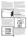
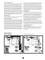
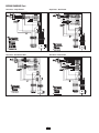
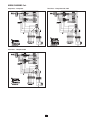
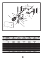
PRH Series
Plenum Heaters
Installation & Maintenance Instructions
Dear Owner,
Congratulations! Thank you for purchasing this new heater manufactured by Marley Engineered Products. You have made a wise
investment selecting the highest quality product in the heating industry. Please carefully read the installation and maintenance
instructions shown in this manual. You should enjoy years of efficient heating comfort with this product from Marley Engineered
Products... the industry’s leader in design, manufacturing, quality and service.
... The Employees of Marley Engineered Products
!
WARNING
Read Carefully - These instructions are written to help
you prevent difficulties that might arise during installation of heaters. Studying the instructions first may save
you considerable time and money later. Observe the
following procedures and cut your installation time to a
minimum.
TO REDUCE RISK OF FIRE OR ELECTRIC SHOCK:
1. Disconnect all power coming to the heater at main service
panel before wiring or servicing.
Note: More than one disconnect may be required.
2. All wiring must be in accordance with national and local
electric codes and the heater must be grounded.
3. Verify the power supply voltage coming to heater matches
the ratings printed on the heater nameplate before energizing.
4. This heater is hot when in use. To avoid burns, do not let
bare skin touch hot surfaces.
5. Do not insert or allow foreign objects to enter any ventilation or exhaust opening as this may cause electric shock,
fire, or damage to heater.
6. Do not block air intakes or exhaust in any manner.
7. A heater has hot and arcing (sparking) parts inside. Do not
use in areas where gasoline, paint, or flammable liquids
are used or stored.
8. Use this heater only as described in this manual. Any other
use not recommended by the manufacturer may cause fire,
electric shock, or injury.
9. This heater is not approved for use in corrosive atmospheres such as marine, green house, or chemical storage
areas.
10. FOR DUCT CONNECTED HEATERS, rated at 0.20”
external static pressure.
SAVE THESE INSTRUCTIONS
Systems) or Canadian equivalent. Every PRH model is
equipped with an inlet and outlet grille for free-air discharge.
Both grilles are intended to be removed when connecting to a
duct system. The inlet and outlet ends of the unit are
equipped with perforated flanges to aid in forming both inlet
and outlet duct flanges (see Figure 3).
GENERAL INFORMATION:
The PRH Series plenum heaters are design certified by ETL to
Standard for Heating and Cooling Equipment ANSI / UL 1995,
CAN/CSA C22.2 No. 236-05, third edition. The PRH Series
plenum heaters are unique application heaters approved for
installation in a concealed space, an area between a finished
ceiling and drop ceiling, a plenum space or inside a plenum.
These series of heaters may be installed in areas that are not
readily accessible and may be installed with a duct system or
installed for free-air discharge. Always install units to operate
within the intended temperature rise, intended external static
pressure range and in the intended installation position (see
Figure 2 horizontal-right).
These perforations will aid in forming a rectangular inlet and
outlet duct flange if they are desired for connection to the duct
system. The unit is designed for a rectangular flange duct connecting and the clear area around the flange is intended for
screw penetration. This feature aids in attaching the duct work
to the unit so that the ductwork may be fastened and sealed to
the unit.
CONTROL ACCESS:
AIRFLOW DIRECTION
The front door allows access to all the controls and components within the unit. The unit is design certified for 0” clearances however, while installing the unit, be careful not to
obstruct access to this control panel. This panel allows access
to the unit for making the power connection, the thermostat
connection and is intended to allow access to all the internal
components that make up the unit.
ELECTRICAL CONNECTIONS:
All field wiring must comply with NEC and local codes.
NOTE: SEE PAGE 3 & 4 FOR WIRING DIAGRAMS
All units are designed for a single point connection to supply
power to the fan and electric heater. The PRH series plenum
heaters are shipped standard with a 80 amp 3-pole disconnect
switch. Field power connections are made to the line side of
this disconnect switch (see Figure 4).
Figure 2
MOUNTING:
The PRH Series plenum heaters are intended to be mounted
in the horizontal-right installation position (see Figure 2) and in
a suspended manner. Suspend the unit from the building
structure in a horizontal plane. Units must be independently
supported. Support channels or straps are intended to be permanently attached to unit frame/housing. Be careful not to
obstruct access to control panel with support channels or
straps. DUCT CONNECTIONS / DUCTING:
Electrical
Knocknot
Ground
Connection
Power
Connection
The PRH Series plenum heaters may either be installed for
free-air discharge or with a duct system. The proper sizing of
warm air ducts is essential in providing satisfactory heating
operation. Ductwork should be in accordance with the latest
editions of NFPA-90B (Warm Air Heating and Air Conditioning
12” Small
11.64” Large
Figure 4
Each unit is equipped with a grounding lug for ground connection. The unit must be properly grounded to comply with NEC
and local codes. Before making the power connection, insure
that the line voltage to the unit matches the ratings located on
the nameplate of the unit. All units should have copper wire
sized for 125% of nameplate amperage. Disconnect the power
supply before wiring the unit and insure the disconnect switch
is in the OFF position while making power connections or servicing the unit. The unit cabinet has a 7/8” electrical knockout
for routing power supply to the disconnect switch (see
Specifications section for knockout location). Should the unit
require a larger electrical conduit connection, this electrical
knockout is intended to serve as the pilot hole in order to field
convert to larger electrical connections.
10”
Small
15.32”
Large
Figure 3
2
stops heating immediately. The fan off delay allows the fan to
continue running to remove all residual heat from the heating
element and will turn the fan off within 60 seconds. Should
there be any abnormal conditions to cause the units limit to
open during the call for heat, the units heat will turn off immediately but the fan will go through its normal off delay. During
this open limit period, the power to the thermostat will be interrupted until the limit closes. This helps in determining abnormalities during heating operation by way of interrupting power
to the thermostat.
CONTROL CONNECTIONS:
The PRH Series plenum heaters are designed to operate from
a 24VAC thermostat. Model TH5220D1003 24V 2 stage thermostat is recommended to be used with the PRH Series
heaters. Thermostat connections are made to the thermostat
board located inside the unit. The thermostat label indicates
which connections are (R, C, W, & G) for making these thermostat connections. The unit cabinet has a 3/8” knockout for
routing thermostat wiring to the units thermostat board (see
Specifications section for knockout location). Instructions for
wiring the thermostat are packed with the thermostat. The unit
is intended to operate with heat (W) and fan (G). If the unit is
intended for cooling signals from the thermostat, make the Y
connection from the thermostat to the G connection on the
unit’s thermostat board.
FAN OPERATION
When there is a demand for fan, the thermostat sends a signal
to the unit for this demand for fan. The unit’s thermostat will
send power to the unit controls to initiate the fan operation.
The call for fan makes the connection on the thermostat board
by powering “G” with “R”. The fan will immediately come on
and continue to run until the demand for fan has ended. When
the fans demand has been met, the fan will immediately turn
off. This breaks the power connection between “R” to “G”.
UNIT OPERATION:
The PRH Series plenum heaters are intended to be operated
from a 24V thermostat. (Model TH5220D1003)
HEATING OPERATION
HEATING OPERATION + FAN OPERATION
When there is a demand for heat, the thermostat sends a signal to the unit for this demand for heat. The unit’s thermostat
board will send power to the unit controls to initiate the heating
operation. The call for heat makes the connection on the thermostat board by powering “W” with “R”. Upon this demand for
heat, the heating element starts heating and the fan on delay
will power the fan within 60 seconds from the call for heat.
The fan delay ensures that there will not be a cold blast of air
to ensure comfort heating. When the heat demand has been
met, the thermostat will send the signal back to the unit’s thermostat board to stop the heating operation. This breaks the
power connection between “R” to “W” and the heating element
When there is a demand for both heat and fan at the same
time, the heating element will come on immediately as well as
the fan. The fan on delay will be bypassed. Upon completion
of the demand for both heat and fan, the heating element will
turn off immediately. However, the off delay will work the same
as during the heating operation.
COOLING OPERATION
Should the unit be used for cooling, the “Y” connection from
the thermostat should be connected to the “G” on the thermostat board. The cooling operation will operate like the fan
operation above.
WIRING DIAGRAMS
Single Phase - Single Element
Three Phase - Single Element 480V
3
WIRING DIAGRAMS Cont.
Three Phase - Single Element
Single Phase - Dual Element
Three Phase - Dual Element 480V
Three Phase - Dual Element
4
WIRING DIAGRAMS Cont.
Single Phase - 2 Stage Heat
Three Phase - 2 Stage Heat 208V, 240V
Three Phase - 2 Stage Heat 480V
5
9
1
6
10
11
2
3
4
8
7
5
Replacement Parts
KEY
1
2
3
4
5
6
7
8
9
10
11
DESCRIPTION
Blower Assembly
Contactor / relay
Time Delay Relay
Fan Relay
Element
208V
240V
277V
480V
Motor
208V
240V
277V
480V
Motor Plug
Primary Limit Control
Capacitor
Disconnect Switch
Transformer
208-240V
277-480V
480V
3KW
1225-2022-000
5018-0005-004
410171001
5018-2024-000
5KW
1225-2022-000
5018-0005-004
410171001
5018-2024-000
7.5KW
1225-10158-000
5018-0005-004
410171001
5018-2024-000
10KW
1225-10158-000
5018-0005-004
410171001
5018-2024-000
15KW
1225-10158-000
5018-0005-004
410171001
5018-2024-000
QTY
1
1
1
1
302006850
302006851
302006838
302006853
302006804
302006852
302006840
302006807
302006809
854
855
302006810
302006804
302006852
302006840
302006807
302006809
854
855
302006810
1
1
1
1
3900-2094-000
3900-2094-000
3900-2095-000
3900-2096-000
6109-8090
1414-2040-000
1432-0002-001
5216-2039-000
3900-2094-000
3900-2094-000
3900-2095-000
3900-2096-000
6109-8090
1414-2040-000
1432-0002-001
5216-2039-000
3900-10160-000
3900-10160-000
3900-10162-000
3900-10164-000
6109-8090
1414-2040-001
1432-0002-001
5216-2039-000
3900-10160-000
3900-10160-000
3900-10162-000
3900-10164-000
6109-8090
1414-2040-001
1432-0002-001
5216-2039-000
3900-10160-000
3900-10160-000
3900-10162-000
3900-10164-000
6109-8090
1414-2040-001
1432-0002-001
5216-2039-000
1
1
1
1
1
1
1
1
5814-0003-000
5814-0003-001
5814-0003-002
5814-0003-000
5814-0003-001
5814-0003-002
5814-0003-000
5814-0003-001
5814-0003-002
5814-0003-000
5814-0003-001
5814-0003-002
5814-0003-000
5814-0003-001
5814-0003-002
1
1
1
6
DIMENSIONS - SMALL CABINET
DIMENSIONS - LARGE CABINET
IMPORTANT INFORMATION
CATALOG NUMBER PHASE
BPH138124
BPH132124
1
BPH137124
BPH138324
BPH132324
3
BPH134324
BPH158124
BPH152124
1
BPH157124
BPH158324
BPH152324
3
BPH154324
BPH158124L
BPH152124L
1
BPH157124L
BPH158324L
BPH152324L
3
BPH154324L
BPH1758124
BPH1752124
1
BPH1757124
BPH1758324
BPH1752324
3
BPH1754324
BPH1102124
1
BPH1107124
BPH2102124
1
BPH2107124
BPH1108324
BPH1102324
3
BPH1104324
BPH2108324
BPH2102324
3
BPH2104324
BPH1158324
BPH1152324
3
BPH1154324
BPH2152324
3
BPH2154324
KW
3
3
5
5
5
5
7.5
7.5
10
10
10
10
15
15
VOLTAGE
208
240
277
208
240
480
208
240
277
208
240
480
208
240
277
208
240
480
208
240
277
208
240
480
240
277
240
277
208
240
480
208
240
480
208
240
480
240
480
AMPS*
15.32
13.4
11.63
9.23
8.12
4.11
24.94
21.73
18.85
14.78
12.93
6.51
24.94
21.73
18.85
14.78
12.93
6.51
38.12
33.31
28.91
22.88
20.1
10.16
43.73
37.93
43.73
37.93
29.82
26.12
13.17
29.82
26.12
13.17
43.9
38.14
19.18
38.14
19.18
LOW SPEED**
CFM
RISE
HIGH SPEED**
CFM
RISE
WT.
LBS
HXWXL
350
27ºF
400
24ºF
49
12.5”x19.5”x24”
350
45ºF
400
39ºF
49
12.5”x19.5”x24”
850
20ºF
1000
16ºF
49
18”x18”x35.5”
850
28ºF
1000
24ºF
69
18”x18”x35.5”
69
18”x18”x35.5”
37ºF
850
37º / 20ºF
31ºF
1000
31º / 16ºF
37ºF
31ºF
850
37º / 20ºF
1000
31º / 16ºF
850
56ºF
1000
47ºFº
850
56º / 28ºF
1000
47º / 24ºF
*Total Amps including Resistive and Inductive loads. **Low and High speed fan operation is determined during installation of thermostat set up
Low speed fan operation not available on 480V models.
7
† Tested @0.2” S.P.
MAINTENANCE & REPAIR
Note: Periodic maintenance and repair should be performed by qualified personnel only.
1. Periodically inspect all electrical connections and terminals to avoid electrical wiring difficulties. Inspect all wiring for frayed or
worn insulation.
2. Periodically and before each heating season, clean the steel finned elements and fan inlet with compressed air, vacuum, or
feather brush. Be sure all electrical covers are tightly closed.
3. If heat output seems to be low, check amperage draw on each element leg. Compare measured values to the correct currents as listed on the unit nameplate.
4. The thermally protected fan motor is permanently lubricated and sealed. No field servicing is required unless needed.
Replace only with a factory supplied identical motor or blower.
5. Check blower rotation to be sure that no is inside blower housing.
TROUBLE SHOOTING
Problem
Potential Cause
1. Motor does not operate. > Fan delay not operating and /or connected.
> Disconnect switch is open
> Blower motor damaged
> No power supply
> Blocked blower wheel
Solution
> Check connections
> Energize circuit
> Verify and relace if necessary
> Verify and energize circuit
> Verify and unblock wheel for proper rotation
2. Heat not working.
> Heating elements are not energized
> Electical components may be open
> Fan delay not connected.
> Safety thermal limits opened
> Incorrect wattage or voltage of element
> Thermostat setting too low
>
>
>
>
>
>
Check connections and operation
Check disconnect, fuses, and circuit breaker
Check connections
Check, verify and replace if necessary
Verify and replace if necessary
Rotate dial clockwise to a higher setting
3. Airflow is insufficient.
> Air filters restriction airflow
> Blocked blower wheel
> Check, clean, and or replace filters
> Verify and unblock wheel for proper rotation.
LIMITED WARRANTY
All products manufactured by Marley Engineered Products are warranted against defects in workmanship and materials for one
year from date of installation, except heating elements which are warranted against defects in workmanship and materials for five
years from date of installation. This warranty does not apply to damage from accident, misuse, or alteration; nor where the connected voltage is more than 5% above the nameplate voltage; nor to equipment improperly installed or wired or maintained in violation of the product’s installation instructions. All claims for warranty work must be accompanied by proof of the date of installation.
The customer shall be responsible for all costs incurred in the removal or reinstallation of products, including labor costs, and shipping costs incurred to return products to Marley Engineered Products Service Center.Within the limitations of this warranty, inoperative units should be returned to the nearest Marley authorized service center or the Marley Engineered Products Service
Center, and we will repair or replace, at our option, at no charge to you with return freight paid by Marley. It is agreed that such
repair or replacement is the exclusive remedy available from Marley Engineered Products.
THE ABOVE WARRANTIES ARE IN LIEU OF ALL OTHER WARRANTIES EXPRESSED OR IMPLIED, AND ALL IMPLIED WARRANTIES OF MERCHANTABILITY AND FITNESS FOR A PARTICULAR PURPOSE WHICH EXCEED THE AFORESAID
EXPRESSED WARRANTIES ARE HEREBY DISCLAIMED AND EXCLUDED FROM THIS AGREEMENT. MARLEY ENGINEERED PRODUCTS SHALL NOT BE LIABLE FOR CONSEQUENTIAL DAMAGES ARISING WITH RESPECT TO THE PRODUCT, WHETHER BASED UPON NEGLIGENCE, TORT, STRICT LIABILITY, OR CONTRACT.
Some states do not allow the exclusion or limitation of incidental or consequential damages, so the above exclusion or limitation
may not apply to you. This warranty gives you specific legal rights, and you may also have other rights which vary from state to
state.
For the address of your nearest authorized service center, contact Marley Engineered Products in Bennettsville, SC, at 1-800-6424328. Merchandise returned to the factory must be accompanied by a return authorization and service identification tag, both available from Marley Engineered Products. When requesting return authorization, include all catalog numbers shown on the products.
Part No. 5200-2834-001
PPD 062
3/08
8
470 Beauty Spot Rd. East
Bennettsville, SC 29512 USA